EP2834662B1 - Robust attenuation correction system for radar reflectivity and differential reflectivity - Google Patents
Robust attenuation correction system for radar reflectivity and differential reflectivity Download PDFInfo
- Publication number
- EP2834662B1 EP2834662B1 EP13770183.5A EP13770183A EP2834662B1 EP 2834662 B1 EP2834662 B1 EP 2834662B1 EP 13770183 A EP13770183 A EP 13770183A EP 2834662 B1 EP2834662 B1 EP 2834662B1
- Authority
- EP
- European Patent Office
- Prior art keywords
- attenuation
- differential
- cost function
- cumulative
- reflectivity
- Prior art date
- Legal status (The legal status is an assumption and is not a legal conclusion. Google has not performed a legal analysis and makes no representation as to the accuracy of the status listed.)
- Active
Links
- 238000002310 reflectometry Methods 0.000 title claims description 45
- 238000012937 correction Methods 0.000 title description 10
- 238000000034 method Methods 0.000 claims description 20
- 230000001186 cumulative effect Effects 0.000 claims description 17
- 238000002592 echocardiography Methods 0.000 claims 6
- 230000006870 function Effects 0.000 description 17
- 230000010287 polarization Effects 0.000 description 9
- XLYOFNOQVPJJNP-UHFFFAOYSA-N water Substances O XLYOFNOQVPJJNP-UHFFFAOYSA-N 0.000 description 5
- 230000002238 attenuated effect Effects 0.000 description 4
- 238000001556 precipitation Methods 0.000 description 4
- 238000010521 absorption reaction Methods 0.000 description 3
- 230000008901 benefit Effects 0.000 description 3
- 230000009977 dual effect Effects 0.000 description 3
- 230000007613 environmental effect Effects 0.000 description 3
- 238000005259 measurement Methods 0.000 description 3
- 238000004891 communication Methods 0.000 description 2
- 238000010586 diagram Methods 0.000 description 2
- 230000000694 effects Effects 0.000 description 2
- 239000007789 gas Substances 0.000 description 2
- 230000015654 memory Effects 0.000 description 2
- 238000005457 optimization Methods 0.000 description 2
- 230000010363 phase shift Effects 0.000 description 2
- 238000012545 processing Methods 0.000 description 2
- 238000004088 simulation Methods 0.000 description 2
- OWNRRUFOJXFKCU-UHFFFAOYSA-N Bromadiolone Chemical compound C=1C=C(C=2C=CC(Br)=CC=2)C=CC=1C(O)CC(C=1C(OC2=CC=CC=C2C=1O)=O)C1=CC=CC=C1 OWNRRUFOJXFKCU-UHFFFAOYSA-N 0.000 description 1
- 230000001133 acceleration Effects 0.000 description 1
- 230000006978 adaptation Effects 0.000 description 1
- 230000008033 biological extinction Effects 0.000 description 1
- 238000005516 engineering process Methods 0.000 description 1
- 238000011156 evaluation Methods 0.000 description 1
- 238000009499 grossing Methods 0.000 description 1
- 230000010354 integration Effects 0.000 description 1
- 238000011545 laboratory measurement Methods 0.000 description 1
- 238000012544 monitoring process Methods 0.000 description 1
- 239000002245 particle Substances 0.000 description 1
- 230000003936 working memory Effects 0.000 description 1
Images








Classifications
-
- G—PHYSICS
- G01—MEASURING; TESTING
- G01S—RADIO DIRECTION-FINDING; RADIO NAVIGATION; DETERMINING DISTANCE OR VELOCITY BY USE OF RADIO WAVES; LOCATING OR PRESENCE-DETECTING BY USE OF THE REFLECTION OR RERADIATION OF RADIO WAVES; ANALOGOUS ARRANGEMENTS USING OTHER WAVES
- G01S13/00—Systems using the reflection or reradiation of radio waves, e.g. radar systems; Analogous systems using reflection or reradiation of waves whose nature or wavelength is irrelevant or unspecified
- G01S13/88—Radar or analogous systems specially adapted for specific applications
- G01S13/95—Radar or analogous systems specially adapted for specific applications for meteorological use
-
- G—PHYSICS
- G01—MEASURING; TESTING
- G01S—RADIO DIRECTION-FINDING; RADIO NAVIGATION; DETERMINING DISTANCE OR VELOCITY BY USE OF RADIO WAVES; LOCATING OR PRESENCE-DETECTING BY USE OF THE REFLECTION OR RERADIATION OF RADIO WAVES; ANALOGOUS ARRANGEMENTS USING OTHER WAVES
- G01S13/00—Systems using the reflection or reradiation of radio waves, e.g. radar systems; Analogous systems using reflection or reradiation of waves whose nature or wavelength is irrelevant or unspecified
- G01S13/88—Radar or analogous systems specially adapted for specific applications
- G01S13/95—Radar or analogous systems specially adapted for specific applications for meteorological use
- G01S13/951—Radar or analogous systems specially adapted for specific applications for meteorological use ground based
-
- G—PHYSICS
- G01—MEASURING; TESTING
- G01S—RADIO DIRECTION-FINDING; RADIO NAVIGATION; DETERMINING DISTANCE OR VELOCITY BY USE OF RADIO WAVES; LOCATING OR PRESENCE-DETECTING BY USE OF THE REFLECTION OR RERADIATION OF RADIO WAVES; ANALOGOUS ARRANGEMENTS USING OTHER WAVES
- G01S13/00—Systems using the reflection or reradiation of radio waves, e.g. radar systems; Analogous systems using reflection or reradiation of waves whose nature or wavelength is irrelevant or unspecified
- G01S13/88—Radar or analogous systems specially adapted for specific applications
- G01S13/95—Radar or analogous systems specially adapted for specific applications for meteorological use
- G01S13/958—Theoretical aspects
-
- Y—GENERAL TAGGING OF NEW TECHNOLOGICAL DEVELOPMENTS; GENERAL TAGGING OF CROSS-SECTIONAL TECHNOLOGIES SPANNING OVER SEVERAL SECTIONS OF THE IPC; TECHNICAL SUBJECTS COVERED BY FORMER USPC CROSS-REFERENCE ART COLLECTIONS [XRACs] AND DIGESTS
- Y02—TECHNOLOGIES OR APPLICATIONS FOR MITIGATION OR ADAPTATION AGAINST CLIMATE CHANGE
- Y02A—TECHNOLOGIES FOR ADAPTATION TO CLIMATE CHANGE
- Y02A90/00—Technologies having an indirect contribution to adaptation to climate change
- Y02A90/10—Information and communication technologies [ICT] supporting adaptation to climate change, e.g. for weather forecasting or climate simulation
Definitions
- a radar system is disposed at the peak of a raised geographical feature such as a hill or mountain 104.
- the radar generates an electromagnetic beam 108 that disperses approximately linearly with distance, with the drawing showing how the width of the beam 108 thus increases with distance from the radar.
- Various examples of weather patterns 116 that might exist and which the system 100 attempts to sample are shown in different positions above the surface 112 of the Earth.
- X-band frequency for example, weather radar signals are attenuated along their paths due to precipitation.
- compensation for such attenuation can be important.
- Embodiments of the invention present weather radar system and a method for determining attenuation in a radar signal in accordance with the appended claims.
- Embodiments of the invention are directed toward attenuation correction of radar data.
- attenuation correction can be very challenging.
- the radar beams propagate through rain and other atmospheric conditions.
- Atmospheric attenuation is a function of atmospheric water drop size and temperature.
- a number of different theoretical models are available that can be used to mathematically describe the particle drop shape that influence the estimate of the attenuation. Each of these models has proven effective in different scenarios. It can be difficult, however, to predict which theoretical model to use.
- the total differential phase gives an idea of the attenuation, but it depends on the model.
- the total attenuation along a rain path must be apportioned to different parts of the radar path in order to correct for attenuation along a radar path.
- Embodiments of this invention allows for a system to apportion the attenuation to different parts of the radar beam.
- Embodiments of the invention also allow for optimization of a number of different theoretical models for both drop size and temperature.
- a cost function can be optimized that is a function of the differential propagation phase, the cumulative attenuation, and the differential attenuation.
- optimal values for the cumulative attenuation and the differential attenuation can be determined for a given model. This process can be repeated for a number of models and for various environmental parameters (e.g., temperature) for each model. In this way, a cumulative attenuation and a differential attenuation value can be returned for each model and parameter. Then the optimal values of the cumulative attenuation and the differential attenuation can be selected from this set. Using these best values, the reflectivity model and the differential reflectivity can be determined.
- Embodiments of the invention also include an estimation of the specific differential propagation phase that is related to or proportional to the reconstructed reflectivity and a reconstructed differential reflectivity.
- the reconstructed specific differential propagation phase can be expressed as a nonlinear functional in terms of reflectivity and differential reflectivity.
- the specific differential propagation phase is nonlinearly proportional to a reconstructed reflectivity and a reconstructed differential reflectivity.
- Embodiments of the invention also include an estimation of the attenuation that is immune to bias fluctuations in the radar system.
- Radar systems require calibration in order to correlate reflectivity values with atmospheric events.
- a radar system that is not calibrated may provide reflectivity data that is positively or negatively biased. For example, a positive bias may result in estimating atmospheric conditions as indicating hail when it is raining because of this bias.
- Embodiments of the invention return radar attenuation values that are immune to or independent from radar bias.
- Light attenuation is the gradual loss of light intensity through a medium. In a vacuum, light spreads as the inverse square of the path the light travels along a distance from the light source. Attenuation is also a function of atmospheric conditions; particular temperature and water drop shape and distribution.
- the microphysical properties of rain medium can be described by drop size distribution (DSD). To study the shape of DSD with widely varying rainfall rates, natural variation of drop size distribution can be expressed in a normalized Gamma model.
- D 0 is the equivolumetric median volume diameter
- ⁇ is a measure of the shape of the shape parameter of the distribution
- N w (mm -1 m -3 ) is the intercept parameter of the exponential distribution with the same water content and D 0 . Radar observations in rain medium can be expressed in terms of DSD.
- ⁇ is the wavelength of the radar and ⁇ h,v represents the radar cross sections at horizontal and vertical polarizations.
- Differential reflectivity (Z dr ) can be defined as the ratio of reflectivity factors at horizontal and vertical polarizations, which is sensitive to drop shape.
- K dp Specific differential phase
- Electromagnetic waves passing through precipitation suffer from power loss resulting from absorption and scattering.
- a rain profiling algorithm can be based on four parameterizations described in equations (10)-(13).
- Z h ′ r Z h ′ r e ⁇ 0.46 ⁇ 0 r ⁇ h s ds ;
- a 1 and a 2 are scaled parameters.
- Z h r r Z h ′ r + ⁇ r 0 r ⁇ h r s ds
- Z v r r Z v ′ r + ⁇ r 0 r ⁇ v r s ds
- Z dr r r Z h r r Z v r r .
- the differential propagation phase, ⁇ dp r is a function of the specific differential phase K dp r and backscattering differential phase ⁇ co r .
- the specific differential phase K dp r is a function of or related to (e.g., proportional, or more specifically, inversely proportional,) the reconstructed reflectivity Z h r r .
- the differential propagation phase, ⁇ dp r is similarly a function of or related to the reconstructed reflectivity Z h r r .
- ⁇ dp ( r ) a cost function (X) can be constructed.
- ⁇ ⁇ ; ⁇ ⁇ dp r ⁇ ⁇ dp r m 10 0.1 A h + A dp .
- the optimal values of A h and A dp can be selected as a minimum value of the cost function.
- ten coefficients (b 1 , c 1 , b 2 , c 2 , b 3 , c 3 , b 4 , a 5 , b 5 , and c 5 ) are used to solve for A h and A dp . These values are used in equations (19a), (19b), (19c), (21b), and (22). The values of these coefficients can depend on the drop shape model, temperature, and/or other environmental parameters.
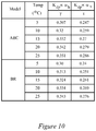
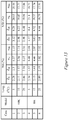
- Figure 2A and 2B show tables that show values for these ten coefficients corresponding to two different rain drop models (A and B) and for various temperatures. These values can be obtained from theoretical simulation with constraints as 15 ⁇ Z h ⁇ 60 dBZ and R ⁇ 150 mm/hr.
- These models can include, for example, the combined model of Andsager et al. ( Andsager, K., K. V. Beard, and N. E Laird, 1999: Laboratory measurements of axis ratios for large raindrops. J Atmos. Sci., 56, 2673 ⁇ 2683 ) and Beard and Chuang ( Bead, K. V. and C. Chuang, 1987: A new model tor the equilibrium shape of raindrops. J Atmos. Sci., 44, 1509---1524 .) model and/or the Brandes et al. model ( Brandes, K A., Cr. Zhang and J. Vivekanandan, 2004: Comparison of polarimetric radar drop size distribution retrieve algorithms. J Atmos. Oceanic Technology., 21, 584-598 ).
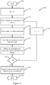
- Figure 3 is a flowchart of process 300 for estimating the best attenuation parameters from a set of attenuation parameters that are selected based on various models and temperatures.
- Process 300 starts at block 305.
- ray profiles of Z h , Z dr and ⁇ dp are input.
- the signal fluctuation in each of these can be reduced by smoothing the input data and/o removed bad data with high signal fluctuation and low signal to noise ratio (SNR).
- the model counter, i is initialized to equal one.
- the model counter indicates the model being used to estimate attenuation parameters.
- These different models include not only different theoretical models, but also different model parameter values for each model.
- Figure 2A and 2B show coefficient values for two models, A and B, for five different temperature values.
- the model counter will count through each temperature for each model for a total of 10 estimations. Any number of models and/or model parameters can be used.
- the minimum and maximum values of A h and A dp can be determined. This can be done by varying the median volume diameter, Do, and the measure of the shape, ⁇ , for all reasonable values in equation 1. For example, 0.5 ⁇ D 0 ⁇ 3.5 mm, 3 ⁇ log 10 N w ⁇ 5 and -1 ⁇ ⁇ ⁇ 4, with the restriction rainfall rate at less than 150 mm/hr and/or the reflectivity set to less than 60 dBZ. Equation (1) can then be used in conjunction with equations (3), (4), (6), (7) and (8) to provide a range of attenuation and differential attenuation values for a given ⁇ dp .
- the minimum and maximum attenuation values can be selected from this group. In other words for a measured ⁇ dp value the maximum and minimum are used to find the bounds of attenuation and differential attenuation.
- fixed minimum and maximum attenuation values can be used instead of calculating these values.
- a set of attenuation pairs, A h and A dp , for various increments between the minimum and maximum values determined at block 315 is created.
- 10 attenuation pairs may be calculated between the minimum and maximum values.
- a cost function value for each attenuation pair can be determined. This can be done, for example, using equation (24). While other cost function may be used, this has been found to be very effective. Some embodiments use a cost function that is directly or inversely proportional to the reconstructed reflectivity values.
- the attenuation pair associated with the lowest cost function value can be selected and/or noted (e.g., saved in memory).
- process 300 proceeds to block 340 where the model counter is incremented. Blocks 315 to 330 can then be repeated for the next model in the model group. In some embodiments, block 315 can have the same range for all models and process 300 can proceed to block 320 after block 340. If, at block 345, the model counter does equal the number of models, N, then process 300 proceeds to block 345.
- Process 300 effectively finds the model that best represents the attenuation that occurs along the specific propagation path.
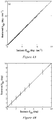
- Figure 4A shows scatterplots of intrinsic K dp and retrieved K dp given by (21a) and (b).
- Figure 4B shows scatterplots of intrinsic ⁇ dp and retrieved ⁇ dp given by (21b).
- Figure 5 shows results of radar observations in polar coordinate map (or Plan position indicators) without measurement noise, but affected by attenuation and differential attenuation.
- Figure 6 shows radar polar maps (or plan position indicators) of attenuation corrected radar reflectivity and differential reflectivity, compared against the intrinsic values of the same.
- Figure 7 shows an explicit quantitative comparison of radar data corrected for attenuation using embodiments of the invention.
- the correction is done for both radar reflectivity and differential reflectivity shows results of radar data with a self-consistent attenuation correction according to some embodiments of the invention.
- Figure 8 shows results of explicit quantitative comparison of radar data corrected for attenuation using the invention.
- the correction is done for both radar reflectivity and differential reflectivity in the presence of measurement noise radar data.
- the intrinsic (true values) are shown on the X axis, and the retrieved results are shown in the Y axis.
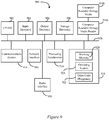
- Figure 9 shows a simplified block diagram of a computer system 900 that can be coupled with a single or dual polarization radar system for computation of environmental parameters using various embodiments of the invention.
- Computer system 900 can be used to perform any or all the computations shown in FIG. 3 and/or FIG. 4 .
- the drawing illustrates how individual system elements can be implemented in a separated or more integrated manner.
- the computer 900 is shown having hardware elements that are electrically coupled via bus 926.
- Network interface 918 can communicatively couple the computational device 900 with another computer, for example, through a network such as the Internet.
- the hardware elements can include a processor 902, an input device 904, an output device 906, a storage device 908, a computer-readable storage media reader 910a, a communications system 914, a processing acceleration unit 916 such as a DSP or special- purpose processor, and memory 918.
- the computer-readable storage media reader 910a can be further connected to a computer-readable storage medium 910b, the combination comprehensively representing remote, local, fixed, and/or removable storage devices plus storage media for temporarily and/or more permanently containing computer-readable information.
- Radar interface 950 is coupled with bus 926.
- radar interface 950 can be any type of communication interface.
- radar interface 950 can be a USB interface, UART interface, serial interface, parallel interface, etc.
- Radar interface 950 can be configured to couple directly with any type of radar system such as a dual polarization radar system.
- the computer system 900 also comprises software elements, shown as being currently located within working memory 920, including an operating system 924 and other code 922, such as a program designed to implement methods and/or processes described herein.
- the other code 922 can include software that provides instructions for receiving user input a dual polarization radar system and manipulating the data according to various embodiments disclosed herein.
- the other code 922 can include software that can predict or forecast weather events, and/or provide real time weather reporting and/or warnings. It will be apparent to those skilled in the art that substantial variations can be used in accordance with specific requirements. For example, customized hardware might also be used and/or particular elements might be implemented in hardware, software (including portable software, such as applets), or both. Further, connection to other computing devices such as network input/output devices can be employed.
Landscapes
- Engineering & Computer Science (AREA)
- Radar, Positioning & Navigation (AREA)
- Remote Sensing (AREA)
- Physics & Mathematics (AREA)
- Electromagnetism (AREA)
- Computer Networks & Wireless Communication (AREA)
- General Physics & Mathematics (AREA)
- Radar Systems Or Details Thereof (AREA)
Description
- One of the fundamental objectives of meteorological radar systems is to sample the atmosphere surrounding the Earth to provide a quantitative measure of precipitation. Conventional meteorological radars provide coverage over long ranges, often on the order of hundreds of kilometers. A general schematic of how such conventional radar systems function is provided in
Fig. 1 . In this illustration, a radar system is disposed at the peak of a raised geographical feature such as a hill ormountain 104. The radar generates anelectromagnetic beam 108 that disperses approximately linearly with distance, with the drawing showing how the width of thebeam 108 thus increases with distance from the radar. Various examples ofweather patterns 116 that might exist and which thesystem 100 attempts to sample are shown in different positions above thesurface 112 of the Earth. - Monitoring of precipitation using higher frequency radar system such as X-band has become popular. At X-band frequency, for example, weather radar signals are attenuated along their paths due to precipitation. Thus, for any quantitative applications that use reflectivity and/or differential reflectivity, compensation for such attenuation can be important.
- The paper "A Dual-Polarization Rain Profiling Algorithm" by Lim and Chandrasekar discloses an attenuation correction algorithm based on profiles of reflectivity, differential reflectivity and differential propagation phase shift.
- The paper "Improved Rain Attenuation Correction Algorithms for Radar Reflectivity and Differential Reflectivity with Adaptation to Drop Shape Model Variation" by Liu, Bringi and Maki describes improved rain attenuation correction algorithms which correct radar reflectivity and differential reflectivity through measured differential propagation phase.
- Embodiments of the invention present weather radar system and a method for determining attenuation in a radar signal in accordance with the appended claims.
- These and other features, aspects, and advantages of the present disclosure are better understood when the following Detailed Description is read with reference to the accompanying drawings.
-
Figure 1 provides a schematic illustration of the operation of a conventional radar system (reproduced from the National Academy of Sciences Report, "Flash flood forecasting over complex terrain"). -
Figure 2A shows relation coefficients of αh ∝ (Zh,Zdr), αv ∝ (Zv,Zdr) and αdp ∝ (Zh,Zdr) according to drop shape model and temperature. -
Figure 2B shows relation coefficients of Kdp ∝ (Zh, αh) and δco ∝ (Kdp, αdp) according to drop shape model and temperature. -
Figure 3 is a flowchart of process for estimating the best attenuation parameters from a set of attenuation parameters that are selected based on various models and temperatures according to some embodiments of the invention. -
Figure 4A shows scatterplots of intrinsic Kdp and retrieved Kdp given by equations (21a) and (b) shown below. -
Figure 4B shows scatterplots of intrinsic δdp and retrieved δdp given by equation (21b) shown below. -
Figure 5 shows results of radar data for (a) attenuated reflectivity, (b) attenuated differential reflectivity, and (c) differential propagation phase shift. -
Figure 6 shows an intrinsic radar data set (non-attenuated) and retrieved (attenuation corrected) using embodiments of the invention. -
Figure 7 shows quantitative results of radar data according to some embodiments of the invention. -
Figure 8 shows results of attenuation correction performed in the presence of measurement noise, and backscatter phase effect. The intrinsic (true) values are shown on the X axis, and the retrieved results are shown in the Y axis. -
Figure 9 shows a simplified block diagram of a computational system that can be used to implement embodiments of the invention. -
Figures 10-11 show relation coefficients for various models and temperatures. -
Figures 12-15 show results of evaluations for several scenarios showing benefits of using embodiments of the invention. - Embodiments of the invention are directed toward attenuation correction of radar data. In weather radar, attenuation correction can be very challenging. The radar beams propagate through rain and other atmospheric conditions. Atmospheric attenuation is a function of atmospheric water drop size and temperature. A number of different theoretical models are available that can be used to mathematically describe the particle drop shape that influence the estimate of the attenuation. Each of these models has proven effective in different scenarios. It can be difficult, however, to predict which theoretical model to use. The total differential phase gives an idea of the attenuation, but it depends on the model. Moreover, the total attenuation along a rain path must be apportioned to different parts of the radar path in order to correct for attenuation along a radar path. Embodiments of this invention allows for a system to apportion the attenuation to different parts of the radar beam. Embodiments of the invention also allow for optimization of a number of different theoretical models for both drop size and temperature.
- In the invention, a cost function can be optimized that is a function of the differential propagation phase, the cumulative attenuation, and the differential attenuation. By optimizing this cost function, optimal values for the cumulative attenuation and the differential attenuation can be determined for a given model. This process can be repeated for a number of models and for various environmental parameters (e.g., temperature) for each model. In this way, a cumulative attenuation and a differential attenuation value can be returned for each model and parameter. Then the optimal values of the cumulative attenuation and the differential attenuation can be selected from this set. Using these best values, the reflectivity model and the differential reflectivity can be determined.
- Embodiments of the invention also include an estimation of the specific differential propagation phase that is related to or proportional to the reconstructed reflectivity and a reconstructed differential reflectivity. For example, the reconstructed specific differential propagation phase can be expressed as a nonlinear functional in terms of reflectivity and differential reflectivity. In some embodiments, the specific differential propagation phase is nonlinearly proportional to a reconstructed reflectivity and a reconstructed differential reflectivity.
- Embodiments of the invention also include an estimation of the attenuation that is immune to bias fluctuations in the radar system. Radar systems require calibration in order to correlate reflectivity values with atmospheric events. A radar system that is not calibrated may provide reflectivity data that is positively or negatively biased. For example, a positive bias may result in estimating atmospheric conditions as indicating hail when it is raining because of this bias. Embodiments of the invention return radar attenuation values that are immune to or independent from radar bias.
- Light attenuation is the gradual loss of light intensity through a medium. In a vacuum, light spreads as the inverse square of the path the light travels along a distance from the light source. Attenuation is also a function of atmospheric conditions; particular temperature and water drop shape and distribution. The microphysical properties of rain medium can be described by drop size distribution (DSD). To study the shape of DSD with widely varying rainfall rates, natural variation of drop size distribution can be expressed in a normalized Gamma model.

- Reflectivity factors Zh,v at horizontal (h) and vertical (v) polarizations can be described as


- The two-way differential propagation phase φdp is expressed in terms of Kdp as

- The measured differential propagation phase can be defined as

- Electromagnetic waves passing through precipitation suffer from power loss resulting from absorption and scattering. Specific attenuation at two polarization states and differential attenuation are related to DSD as


- Two-way cumulative attenuation Ah and differential attenuation Adp can be expressed as


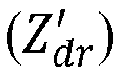

- In some embodiments, a rain profiling algorithm can be based on four parameterizations described in equations (10)-(13).


- After modest algebraic manipulation, solutions for αh and αv are obtained as


- After minor algebraic manipulation of (14) and (15) with (16a) and (16b), solutions for αh and αv are expressed as (17a) and (17b). The solutions are combination of forward and backward solution.


- These equations return a specific attenuations, αh and αv , that are immune to radar equipment bias. Radar bias is returned as a power shift in the reflectivity values Zv and Zh . The terms Iv and Ih are proportional to reflectivity values Zv and Zh raised to the power of a couple parameters. The terms Iv and Ih are found in the denominators of 17(a) and 17(b) solving for the specific attenuations, αh and αv . And Zv and Zh raised to the power of a couple parameters are found in the numerator raised to the same power. Thus, the reflectivity values Zv and Zh , which include any bias shift information, do not affect the equations.
- With estimated αh and αv, Zh, Zv and Zdr can be estimated as


- After first estimation, αh and αv are retrieved by scaled formula of (11) using retrieved value of Zh and Zdr from (18) as


- Here a1 and a2 are scaled parameters. After retrieving αh and αv, Zh, Zv and Zdr are retrieved as


- To find optimal values of Ah and Adp at (17a) and (17b), an optimization process is carried out. At first step, using retrieved αh, αdp and Zh at (19a,c) and (20a), specific differential phase


- The advantage of formulas (21a,b) and (22) is it is not affected by biases of Zh and Zdr. The simulation is carryout out for widely varying DSD (0.5 ≤ D0 ≤ 3.5 mm, 3 ≤ log10Nw ≤ 5 and -1 ≤ µ ≤ 4) with constraints of R < 150 mmhr-1 and 15 < Zh < 60dBZ.
- Moreover, combining (19a) with (21a) we can note that


- At second step, by using retrieved


- As noted in above equations, the differential propagation phase,


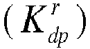

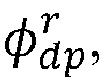

- Next, by comparing reconstructed


- The optimal values of Ah and Adp can be selected as a minimum value of the cost function.
- As shown above, ten coefficients (b1, c1, b2, c2, b3, c3, b4, a5, b5, and c5) are used to solve for Ah and Adp. These values are used in equations (19a), (19b), (19c), (21b), and (22). The values of these coefficients can depend on the drop shape model, temperature, and/or other environmental parameters.
Figure 2A and 2B show tables that show values for these ten coefficients corresponding to two different rain drop models (A and B) and for various temperatures. These values can be obtained from theoretical simulation with constraints as 15 < Zh < 60 dBZ and R < 150 mm/hr. - These models can include, for example, the combined model of Andsager et al. (Andsager, K., K. V. Beard, and N. E Laird, 1999: Laboratory measurements of axis ratios for large raindrops. J Atmos. Sci., 56, 2673∼2683) and Beard and Chuang (Bead, K. V. and C. Chuang, 1987: A new model tor the equilibrium shape of raindrops. J Atmos. Sci., 44, 1509---1524.) model and/or the Brandes et al. model (Brandes, K A., Cr. Zhang and J. Vivekanandan, 2004: Comparison of polarimetric radar drop size distribution retrieve algorithms. J Atmos. Oceanic Technology., 21, 584-598).
-
Figure 3 is a flowchart ofprocess 300 for estimating the best attenuation parameters from a set of attenuation parameters that are selected based on various models and temperatures. Process 300 starts atblock 305. - Prior to starting
processing 300, ray profiles of Zh, Zdr and φdp are input. The signal fluctuation in each of these can be reduced by smoothing the input data and/o removed bad data with high signal fluctuation and low signal to noise ratio (SNR). - At
block 310 the model counter, i, is initialized to equal one. The model counter indicates the model being used to estimate attenuation parameters. These different models include not only different theoretical models, but also different model parameter values for each model. For example,Figure 2A and 2B show coefficient values for two models, A and B, for five different temperature values. In this example, the model counter will count through each temperature for each model for a total of 10 estimations. Any number of models and/or model parameters can be used. - At
block 315 the minimum and maximum values of Ah and Adp can be determined. This can be done by varying the median volume diameter, Do, and the measure of the shape, µ, for all reasonable values inequation 1. For example, 0.5 ≤ D0 ≤ 3.5 mm, 3 ≤ log10Nw ≤ 5 and -1 ≤ µ ≤ 4, with the restriction rainfall rate at less than 150 mm/hr and/or the reflectivity set to less than 60 dBZ. Equation (1) can then be used in conjunction with equations (3), (4), (6), (7) and (8) to provide a range of attenuation and differential attenuation values for a given φ dp . The minimum and maximum attenuation values can be selected from this group. In other words for a measured φdp value the maximum and minimum are used to find the bounds of attenuation and differential attenuation. - In some embodiments, fixed minimum and maximum attenuation values can be used instead of calculating these values.
- At block 320 a set of attenuation pairs, Ah and Adp, for various increments between the minimum and maximum values determined at
block 315 is created. For example, 10 attenuation pairs may be calculated between the minimum and maximum values. The attenuation pairs can be set up as equispaced values between the minimum and maximum values. For example, if the minimum Ah= 1 and maximum Ah= 5, then Ah1=1, Ah2=1 .5, Ah3=2.0, ... Ah11=5. Similar values can be found for Adp across the range from its minimum to maximum. In this example, eleven values for Ah were used. Eleven can also be used for Adp. Any number of intervals can be used. - At
block 325, a cost function value for each attenuation pair can be determined. This can be done, for example, using equation (24). While other cost function may be used, this has been found to be very effective. Some embodiments use a cost function that is directly or inversely proportional to the reconstructed reflectivity values. Atblock 330 the attenuation pair associated with the lowest cost function value can be selected and/or noted (e.g., saved in memory). - If, at
block 345, the model counter does not equal the number of models, N, then process 300 proceeds to block 340 where the model counter is incremented.Blocks 315 to 330 can then be repeated for the next model in the model group. In some embodiments, block 315 can have the same range for all models andprocess 300 can proceed to block 320 afterblock 340. If, atblock 345, the model counter does equal the number of models, N, then process 300 proceeds to block 345. - At this point of
process 300, a set of attenuation pairs associated with the lowest cost function have been selected and/or noted for each model. Then, atblock 345, the attenuation pairs associated with the lowest cost function can be selected from this set of attenuation pairs and returned.Process 300 can then end atblock 350.Process 300 effectively finds the model that best represents the attenuation that occurs along the specific propagation path. - Once the optimized Ah and Adp have been selected, the coefficients are known. Moreover, Zh, Zdr, αh and αv can be determined.
-
Figure 4A shows scatterplots of intrinsic Kdp and retrieved Kdp given by (21a) and (b). -
Figure 4B shows scatterplots of intrinsic δdp and retrieved δdp given by (21b). -
Figure 5 shows results of radar observations in polar coordinate map (or Plan position indicators) without measurement noise, but affected by attenuation and differential attenuation. -
Figure 6 shows radar polar maps (or plan position indicators) of attenuation corrected radar reflectivity and differential reflectivity, compared against the intrinsic values of the same.. -
Figure 7 shows an explicit quantitative comparison of radar data corrected for attenuation using embodiments of the invention. The correction is done for both radar reflectivity and differential reflectivity shows results of radar data with a self-consistent attenuation correction according to some embodiments of the invention. -
Figure 8 shows results of explicit quantitative comparison of radar data corrected for attenuation using the invention. The correction is done for both radar reflectivity and differential reflectivity in the presence of measurement noise radar data. The intrinsic (true values) are shown on the X axis, and the retrieved results are shown in the Y axis. -
Figure 9 shows a simplified block diagram of acomputer system 900 that can be coupled with a single or dual polarization radar system for computation of environmental parameters using various embodiments of the invention.Computer system 900 can be used to perform any or all the computations shown inFIG. 3 and/orFIG. 4 . The drawing illustrates how individual system elements can be implemented in a separated or more integrated manner. Thecomputer 900 is shown having hardware elements that are electrically coupled viabus 926.Network interface 918 can communicatively couple thecomputational device 900 with another computer, for example, through a network such as the Internet. The hardware elements can include aprocessor 902, aninput device 904, anoutput device 906, astorage device 908, a computer-readablestorage media reader 910a, acommunications system 914, aprocessing acceleration unit 916 such as a DSP or special- purpose processor, andmemory 918. The computer-readablestorage media reader 910a can be further connected to a computer-readable storage medium 910b, the combination comprehensively representing remote, local, fixed, and/or removable storage devices plus storage media for temporarily and/or more permanently containing computer-readable information. -
Radar interface 950 is coupled withbus 926. In some embodiments,radar interface 950 can be any type of communication interface. For example,radar interface 950 can be a USB interface, UART interface, serial interface, parallel interface, etc.Radar interface 950 can be configured to couple directly with any type of radar system such as a dual polarization radar system. - The
computer system 900 also comprises software elements, shown as being currently located within workingmemory 920, including anoperating system 924 andother code 922, such as a program designed to implement methods and/or processes described herein. In some embodiments, theother code 922 can include software that provides instructions for receiving user input a dual polarization radar system and manipulating the data according to various embodiments disclosed herein. In some embodiments, theother code 922 can include software that can predict or forecast weather events, and/or provide real time weather reporting and/or warnings. It will be apparent to those skilled in the art that substantial variations can be used in accordance with specific requirements. For example, customized hardware might also be used and/or particular elements might be implemented in hardware, software (including portable software, such as applets), or both. Further,
connection to other computing devices such as network input/output devices can be employed.
Claims (8)
- A weather radar system comprising:a transmitter configured to transmit a weather radar signal into a region of interest;a receiver configured to receive echoes scattered from the region of interest, anda computer system coupled at least with the receiver, wherein the computer system is configured to:calculate a plurality of attenuation pairs from the received echoes (320), wherein each attenuation pair comprises a cumulative attenuation and a differential attenuation from the received echoes;solve a cost function for each of the attenuation pairs (325), wherein the cost function returns a cost function value for each attenuation pair; anddetermine the attenuation pair associated with the minimum cost function value (330), characterised in that the cost function is a function of the differential propagation phase, the cumulative attenuation, and the differential attenuation, wherein the cost function comprises



- The weather radar system according to claim 1, wherein the cumulative attenuation of the plurality of attenuation pairs is calculated between an estimated maximum cumulative attenuation value and an estimated minimum cumulative attenuation value.
- The weather radar system according to claim 1, wherein the differential attenuation of the plurality of attenuation pairs is calculated between an estimated maximum differential attenuation value and an estimated minimum differential attenuation value.
- A method for determining attenuation in a radar signal, the method comprising:transmitting a radar signal into the atmosphere from a weather radar system;receiving echoes from the atmosphere in response to the radar signal at the weather radar system;calculating a plurality of attenuation pairs from the received echoes (320), wherein each attenuation pair comprises a cumulative attenuation and a differential attenuation from the received echoes;solving a cost function for each of the attenuation pairs (325), wherein the cost function returns a cost function value for each attenuation pair; anddetermining the attenuation pair associated with the minimum cost function value (330), characterised in that the cost function is a function of the differential propagation phase, the cumulative attenuation, and the differential attenuation, wherein the cost function comprises


- The method for determining attenuation in a radar signal according to claim 4, wherein the cumulative attenuation of the plurality of attenuation pairs is calculated between an estimated maximum cumulative attenuation value and an estimated minimum cumulative attenuation value.
- The method for determining attenuation in a radar signal according to claim 4, wherein the differential attenuation of the plurality of attenuation pairs is calculated between an estimated maximum differential attenuation value and an estimated minimum differential attenuation value.
- The method for determining attenuation in a radar signal according to claim 4, wherein the cost function is a function of the differential reflectivity and is proportional to a reflectivity factor.
- The method for determining attenuation in a radar signal according to claim 4, further comprising determining a plurality of model coefficients from the attenuation pair.
Applications Claiming Priority (3)
| Application Number | Priority Date | Filing Date | Title |
|---|---|---|---|
| US201261616029P | 2012-03-27 | 2012-03-27 | |
| US13/842,065 US9465106B2 (en) | 2012-03-27 | 2013-03-15 | Robust attenuation correction system for radar reflectivity and differential reflectivity |
| PCT/US2013/033904 WO2013148703A1 (en) | 2012-03-27 | 2013-03-26 | Robust attenuation correction system for radar reflectivity and differential reflectivity |
Publications (3)
| Publication Number | Publication Date |
|---|---|
| EP2834662A1 EP2834662A1 (en) | 2015-02-11 |
| EP2834662A4 EP2834662A4 (en) | 2015-12-23 |
| EP2834662B1 true EP2834662B1 (en) | 2019-01-23 |
Family
ID=49261176
Family Applications (1)
| Application Number | Title | Priority Date | Filing Date |
|---|---|---|---|
| EP13770183.5A Active EP2834662B1 (en) | 2012-03-27 | 2013-03-26 | Robust attenuation correction system for radar reflectivity and differential reflectivity |
Country Status (3)
| Country | Link |
|---|---|
| US (1) | US9465106B2 (en) |
| EP (1) | EP2834662B1 (en) |
| WO (1) | WO2013148703A1 (en) |
Families Citing this family (12)
| Publication number | Priority date | Publication date | Assignee | Title |
|---|---|---|---|---|
| US10416351B2 (en) * | 2015-09-10 | 2019-09-17 | The Climate Corporation | Generating probabilistic estimates of rainfall rates from radar reflectivity measurements |
| CN106324580B (en) * | 2016-11-02 | 2018-11-06 | 中国人民解放军理工大学 | A kind of radar return decaying correction method based on microwave links road network |
| CN107656279B (en) * | 2017-09-19 | 2021-03-16 | 中国电子科技集团公司第三十八研究所 | A Precipitation Radar Radiation Transfer System Based on Two-parameter Particle Spectral Distribution |
| KR101872025B1 (en) * | 2017-12-18 | 2018-06-27 | 한국건설기술연구원 | Specific differential propagation phase apparatus and method using dual-polarization radar observation |
| CN113985378B (en) * | 2021-12-30 | 2022-03-11 | 雷象科技(北京)有限公司 | Array weather radar attenuation correction method |
| CN114675277B (en) * | 2022-03-25 | 2022-11-04 | 中国人民解放军国防科技大学 | Near-ground atmosphere refractive index profile monitoring method based on commercial microwave return link |
| CN115061105B (en) * | 2022-06-30 | 2023-07-14 | 广东纳睿雷达科技股份有限公司 | Dual-polarization radar rapid calibration method, device and storage medium |
| CN115932766B (en) * | 2022-12-15 | 2024-03-22 | 佛山市龙卷风研究中心 | Phased array radar data correction system |
| CN117805762B (en) * | 2023-12-29 | 2026-05-12 | 北京理工大学 | Differential phase and attenuation joint estimation method for dual-polarized weather radar |
| US20260004405A1 (en) * | 2024-06-28 | 2026-01-01 | Waymo Llc | Methods and Systems for Mitigating the Effects of Weather-related Attenuation on Radar Imagery |
| CN120275914B (en) * | 2025-03-21 | 2025-12-02 | 中国气象科学研究院 | Radar echo attenuation correction methods, devices, electronic equipment, media and products |
| CN120802196B (en) * | 2025-09-16 | 2025-11-28 | 南京信息工程大学 | A method and system for synchronous correction of attenuation and deviation in X-band rain-measuring radar |
Family Cites Families (7)
| Publication number | Priority date | Publication date | Assignee | Title |
|---|---|---|---|---|
| US5196854A (en) * | 1991-06-13 | 1993-03-23 | Westinghouse Electric Corp. | Inflight weather and ground mapping radar |
| FR2742876B1 (en) * | 1995-12-26 | 1998-02-06 | Thomson Csf | METHOD FOR DETERMINING THE PRECIPITATION RATE BY DUAL POLARIZATION RADAR AND METEOROLOGICAL RADAR USING THE SAME |
| US7589666B2 (en) * | 2004-12-30 | 2009-09-15 | Vaisala, Inc. | System and method for processing data in weather radar |
| US7518544B2 (en) * | 2006-07-13 | 2009-04-14 | Colorado State University Research Foundation | Retrieval of parameters in networked radar environments |
| US8325084B2 (en) * | 2007-03-13 | 2012-12-04 | Baron Services, Inc. | System for calibration of dual polarization radar with built-in test couplers |
| JP2011059078A (en) * | 2009-09-14 | 2011-03-24 | Toshiba Corp | Dual polarization radar apparatus and interference determining method |
| FR2960651B1 (en) * | 2010-05-28 | 2013-08-23 | Thales Sa | METHOD FOR CORRECTING REFLECTIVITY MEASUREMENTS AND RADAR USING THE SAME |
-
2013
- 2013-03-15 US US13/842,065 patent/US9465106B2/en not_active Expired - Fee Related
- 2013-03-26 EP EP13770183.5A patent/EP2834662B1/en active Active
- 2013-03-26 WO PCT/US2013/033904 patent/WO2013148703A1/en not_active Ceased
Non-Patent Citations (1)
| Title |
|---|
| None * |
Also Published As
| Publication number | Publication date |
|---|---|
| WO2013148703A1 (en) | 2013-10-03 |
| EP2834662A1 (en) | 2015-02-11 |
| EP2834662A4 (en) | 2015-12-23 |
| US20130271313A1 (en) | 2013-10-17 |
| US9465106B2 (en) | 2016-10-11 |
Similar Documents
| Publication | Publication Date | Title |
|---|---|---|
| US9465106B2 (en) | Robust attenuation correction system for radar reflectivity and differential reflectivity | |
| US8502727B2 (en) | Method of correcting reflectivity measurements and radar implementing this method | |
| Leijnse et al. | Microwave link rainfall estimation: Effects of link length and frequency, temporal sampling, power resolution, and wet antenna attenuation | |
| Trömel et al. | Backscatter differential phase—Estimation and variability | |
| EP2286511B1 (en) | Dual-polarization radar processing system using time domain method | |
| US9348015B2 (en) | Integrated rainfall estimation method using X-band dual-polarimetric radar measurement data | |
| Sebastianelli et al. | On precipitation measurements collected by a weather radar and a rain gauge network | |
| Marzano et al. | Investigating precipitation microphysics using ground-based microwave remote sensors and disdrometer data | |
| Vivekanandan et al. | Radar reflectivity calibration using differential propagation phase measurement | |
| Augros et al. | Comparisons between S‐, C‐and X‐band polarimetric radar observations and convective‐scale simulations of the HyMeX first special observing period | |
| CN110361742A (en) | Cloud rain micro physical parameter inversion method based on satellite-borne three-frequency millimeter wave radar | |
| US20090033542A1 (en) | Ground clutter mitigation using a parametric time domain method | |
| Goldhirsh et al. | Estimation of raindrop size distribution using multiple wavelength radar systems | |
| Schneebeli et al. | Improved estimation of the specific differential phase shift using a compilation of Kalman filter ensembles | |
| CN114942076B (en) | Sea surface temperature correction method and device | |
| CN120850578A (en) | A method for correcting rainfall effects on Ku-band satellite scatterometer observations | |
| CN117741665A (en) | Precipitation intensity estimation method and device, electronic equipment and storage medium | |
| CN109884605A (en) | Extracting method of the sexual intercourse to attenuation by absorption and the Mie scattering decaying of radar signal | |
| Lim et al. | A robust attenuation correction system for reflectivity and differential reflectivity in weather radars | |
| EP3401709A1 (en) | Method for determining the presence of meteorological precipitations | |
| Park et al. | Calibration of radar reflectivity measurements from the KMA operational radar network | |
| You et al. | A statistical approach to radar rainfall estimates using polarimetric variables | |
| Kim et al. | Validation of composite polarimetric parameters and rainfall rates from an X-band dual-polarization radar network in the Tokyo metropolitan area | |
| Vulpiani et al. | Rainfall rate retrieval in presence of path attenuation using C-band polarimetric weather radars | |
| Sheppard | Sampling errors in the measurement of rainfall parameters using the Precipitation Occurrence Sensor System (POSS) |
Legal Events
| Date | Code | Title | Description |
|---|---|---|---|
| PUAI | Public reference made under article 153(3) epc to a published international application that has entered the european phase |
Free format text: ORIGINAL CODE: 0009012 |
|
| 17P | Request for examination filed |
Effective date: 20140715 |
|
| AK | Designated contracting states |
Kind code of ref document: A1 Designated state(s): AL AT BE BG CH CY CZ DE DK EE ES FI FR GB GR HR HU IE IS IT LI LT LU LV MC MK MT NL NO PL PT RO RS SE SI SK SM TR |
|
| AX | Request for extension of the european patent |
Extension state: BA ME |
|
| DAX | Request for extension of the european patent (deleted) | ||
| RA4 | Supplementary search report drawn up and despatched (corrected) |
Effective date: 20151123 |
|
| RIC1 | Information provided on ipc code assigned before grant |
Ipc: G01S 13/95 20060101AFI20151117BHEP |
|
| STAA | Information on the status of an ep patent application or granted ep patent |
Free format text: STATUS: EXAMINATION IS IN PROGRESS |
|
| 17Q | First examination report despatched |
Effective date: 20170315 |
|
| GRAP | Despatch of communication of intention to grant a patent |
Free format text: ORIGINAL CODE: EPIDOSNIGR1 |
|
| STAA | Information on the status of an ep patent application or granted ep patent |
Free format text: STATUS: GRANT OF PATENT IS INTENDED |
|
| INTG | Intention to grant announced |
Effective date: 20180808 |
|
| GRAS | Grant fee paid |
Free format text: ORIGINAL CODE: EPIDOSNIGR3 |
|
| GRAA | (expected) grant |
Free format text: ORIGINAL CODE: 0009210 |
|
| STAA | Information on the status of an ep patent application or granted ep patent |
Free format text: STATUS: THE PATENT HAS BEEN GRANTED |
|
| AK | Designated contracting states |
Kind code of ref document: B1 Designated state(s): AL AT BE BG CH CY CZ DE DK EE ES FI FR GB GR HR HU IE IS IT LI LT LU LV MC MK MT NL NO PL PT RO RS SE SI SK SM TR |
|
| REG | Reference to a national code |
Ref country code: GB Ref legal event code: FG4D |
|
| REG | Reference to a national code |
Ref country code: CH Ref legal event code: EP |
|
| REG | Reference to a national code |
Ref country code: AT Ref legal event code: REF Ref document number: 1091881 Country of ref document: AT Kind code of ref document: T Effective date: 20190215 |
|
| REG | Reference to a national code |
Ref country code: IE Ref legal event code: FG4D |
|
| REG | Reference to a national code |
Ref country code: DE Ref legal event code: R096 Ref document number: 602013050232 Country of ref document: DE |
|
| REG | Reference to a national code |
Ref country code: NL Ref legal event code: MP Effective date: 20190123 |
|
| PG25 | Lapsed in a contracting state [announced via postgrant information from national office to epo] |
Ref country code: NL Free format text: LAPSE BECAUSE OF FAILURE TO SUBMIT A TRANSLATION OF THE DESCRIPTION OR TO PAY THE FEE WITHIN THE PRESCRIBED TIME-LIMIT Effective date: 20190123 |
|
| PG25 | Lapsed in a contracting state [announced via postgrant information from national office to epo] |
Ref country code: SE Free format text: LAPSE BECAUSE OF FAILURE TO SUBMIT A TRANSLATION OF THE DESCRIPTION OR TO PAY THE FEE WITHIN THE PRESCRIBED TIME-LIMIT Effective date: 20190123 Ref country code: PT Free format text: LAPSE BECAUSE OF FAILURE TO SUBMIT A TRANSLATION OF THE DESCRIPTION OR TO PAY THE FEE WITHIN THE PRESCRIBED TIME-LIMIT Effective date: 20190523 Ref country code: PL Free format text: LAPSE BECAUSE OF FAILURE TO SUBMIT A TRANSLATION OF THE DESCRIPTION OR TO PAY THE FEE WITHIN THE PRESCRIBED TIME-LIMIT Effective date: 20190123 Ref country code: ES Free format text: LAPSE BECAUSE OF FAILURE TO SUBMIT A TRANSLATION OF THE DESCRIPTION OR TO PAY THE FEE WITHIN THE PRESCRIBED TIME-LIMIT Effective date: 20190123 Ref country code: LT Free format text: LAPSE BECAUSE OF FAILURE TO SUBMIT A TRANSLATION OF THE DESCRIPTION OR TO PAY THE FEE WITHIN THE PRESCRIBED TIME-LIMIT Effective date: 20190123 Ref country code: NO Free format text: LAPSE BECAUSE OF FAILURE TO SUBMIT A TRANSLATION OF THE DESCRIPTION OR TO PAY THE FEE WITHIN THE PRESCRIBED TIME-LIMIT Effective date: 20190423 Ref country code: FI Free format text: LAPSE BECAUSE OF FAILURE TO SUBMIT A TRANSLATION OF THE DESCRIPTION OR TO PAY THE FEE WITHIN THE PRESCRIBED TIME-LIMIT Effective date: 20190123 |
|
| REG | Reference to a national code |
Ref country code: AT Ref legal event code: MK05 Ref document number: 1091881 Country of ref document: AT Kind code of ref document: T Effective date: 20190123 |
|
| PG25 | Lapsed in a contracting state [announced via postgrant information from national office to epo] |
Ref country code: IS Free format text: LAPSE BECAUSE OF FAILURE TO SUBMIT A TRANSLATION OF THE DESCRIPTION OR TO PAY THE FEE WITHIN THE PRESCRIBED TIME-LIMIT Effective date: 20190523 Ref country code: BG Free format text: LAPSE BECAUSE OF FAILURE TO SUBMIT A TRANSLATION OF THE DESCRIPTION OR TO PAY THE FEE WITHIN THE PRESCRIBED TIME-LIMIT Effective date: 20190423 Ref country code: HR Free format text: LAPSE BECAUSE OF FAILURE TO SUBMIT A TRANSLATION OF THE DESCRIPTION OR TO PAY THE FEE WITHIN THE PRESCRIBED TIME-LIMIT Effective date: 20190123 Ref country code: RS Free format text: LAPSE BECAUSE OF FAILURE TO SUBMIT A TRANSLATION OF THE DESCRIPTION OR TO PAY THE FEE WITHIN THE PRESCRIBED TIME-LIMIT Effective date: 20190123 Ref country code: LV Free format text: LAPSE BECAUSE OF FAILURE TO SUBMIT A TRANSLATION OF THE DESCRIPTION OR TO PAY THE FEE WITHIN THE PRESCRIBED TIME-LIMIT Effective date: 20190123 Ref country code: GR Free format text: LAPSE BECAUSE OF FAILURE TO SUBMIT A TRANSLATION OF THE DESCRIPTION OR TO PAY THE FEE WITHIN THE PRESCRIBED TIME-LIMIT Effective date: 20190424 |
|
| REG | Reference to a national code |
Ref country code: DE Ref legal event code: R097 Ref document number: 602013050232 Country of ref document: DE |
|
| PG25 | Lapsed in a contracting state [announced via postgrant information from national office to epo] |
Ref country code: AL Free format text: LAPSE BECAUSE OF FAILURE TO SUBMIT A TRANSLATION OF THE DESCRIPTION OR TO PAY THE FEE WITHIN THE PRESCRIBED TIME-LIMIT Effective date: 20190123 Ref country code: MC Free format text: LAPSE BECAUSE OF FAILURE TO SUBMIT A TRANSLATION OF THE DESCRIPTION OR TO PAY THE FEE WITHIN THE PRESCRIBED TIME-LIMIT Effective date: 20190123 Ref country code: SK Free format text: LAPSE BECAUSE OF FAILURE TO SUBMIT A TRANSLATION OF THE DESCRIPTION OR TO PAY THE FEE WITHIN THE PRESCRIBED TIME-LIMIT Effective date: 20190123 Ref country code: EE Free format text: LAPSE BECAUSE OF FAILURE TO SUBMIT A TRANSLATION OF THE DESCRIPTION OR TO PAY THE FEE WITHIN THE PRESCRIBED TIME-LIMIT Effective date: 20190123 Ref country code: DK Free format text: LAPSE BECAUSE OF FAILURE TO SUBMIT A TRANSLATION OF THE DESCRIPTION OR TO PAY THE FEE WITHIN THE PRESCRIBED TIME-LIMIT Effective date: 20190123 Ref country code: IT Free format text: LAPSE BECAUSE OF FAILURE TO SUBMIT A TRANSLATION OF THE DESCRIPTION OR TO PAY THE FEE WITHIN THE PRESCRIBED TIME-LIMIT Effective date: 20190123 Ref country code: CZ Free format text: LAPSE BECAUSE OF FAILURE TO SUBMIT A TRANSLATION OF THE DESCRIPTION OR TO PAY THE FEE WITHIN THE PRESCRIBED TIME-LIMIT Effective date: 20190123 Ref country code: RO Free format text: LAPSE BECAUSE OF FAILURE TO SUBMIT A TRANSLATION OF THE DESCRIPTION OR TO PAY THE FEE WITHIN THE PRESCRIBED TIME-LIMIT Effective date: 20190123 |
|
| REG | Reference to a national code |
Ref country code: CH Ref legal event code: PL |
|
| PG25 | Lapsed in a contracting state [announced via postgrant information from national office to epo] |
Ref country code: SM Free format text: LAPSE BECAUSE OF FAILURE TO SUBMIT A TRANSLATION OF THE DESCRIPTION OR TO PAY THE FEE WITHIN THE PRESCRIBED TIME-LIMIT Effective date: 20190123 Ref country code: LU Free format text: LAPSE BECAUSE OF NON-PAYMENT OF DUE FEES Effective date: 20190326 |
|
| PLBE | No opposition filed within time limit |
Free format text: ORIGINAL CODE: 0009261 |
|
| REG | Reference to a national code |
Ref country code: BE Ref legal event code: MM Effective date: 20190331 |
|
| STAA | Information on the status of an ep patent application or granted ep patent |
Free format text: STATUS: NO OPPOSITION FILED WITHIN TIME LIMIT |
|
| GBPC | Gb: european patent ceased through non-payment of renewal fee |
Effective date: 20190423 |
|
| PG25 | Lapsed in a contracting state [announced via postgrant information from national office to epo] |
Ref country code: AT Free format text: LAPSE BECAUSE OF FAILURE TO SUBMIT A TRANSLATION OF THE DESCRIPTION OR TO PAY THE FEE WITHIN THE PRESCRIBED TIME-LIMIT Effective date: 20190123 |
|
| 26N | No opposition filed |
Effective date: 20191024 |
|
| PG25 | Lapsed in a contracting state [announced via postgrant information from national office to epo] |
Ref country code: IE Free format text: LAPSE BECAUSE OF NON-PAYMENT OF DUE FEES Effective date: 20190326 Ref country code: CH Free format text: LAPSE BECAUSE OF NON-PAYMENT OF DUE FEES Effective date: 20190331 Ref country code: LI Free format text: LAPSE BECAUSE OF NON-PAYMENT OF DUE FEES Effective date: 20190331 Ref country code: GB Free format text: LAPSE BECAUSE OF NON-PAYMENT OF DUE FEES Effective date: 20190423 |
|
| PG25 | Lapsed in a contracting state [announced via postgrant information from national office to epo] |
Ref country code: FR Free format text: LAPSE BECAUSE OF NON-PAYMENT OF DUE FEES Effective date: 20190331 Ref country code: BE Free format text: LAPSE BECAUSE OF NON-PAYMENT OF DUE FEES Effective date: 20190331 Ref country code: SI Free format text: LAPSE BECAUSE OF FAILURE TO SUBMIT A TRANSLATION OF THE DESCRIPTION OR TO PAY THE FEE WITHIN THE PRESCRIBED TIME-LIMIT Effective date: 20190123 |
|
| PG25 | Lapsed in a contracting state [announced via postgrant information from national office to epo] |
Ref country code: TR Free format text: LAPSE BECAUSE OF FAILURE TO SUBMIT A TRANSLATION OF THE DESCRIPTION OR TO PAY THE FEE WITHIN THE PRESCRIBED TIME-LIMIT Effective date: 20190123 |
|
| PG25 | Lapsed in a contracting state [announced via postgrant information from national office to epo] |
Ref country code: MT Free format text: LAPSE BECAUSE OF NON-PAYMENT OF DUE FEES Effective date: 20190326 |
|
| PG25 | Lapsed in a contracting state [announced via postgrant information from national office to epo] |
Ref country code: CY Free format text: LAPSE BECAUSE OF FAILURE TO SUBMIT A TRANSLATION OF THE DESCRIPTION OR TO PAY THE FEE WITHIN THE PRESCRIBED TIME-LIMIT Effective date: 20190123 |
|
| PG25 | Lapsed in a contracting state [announced via postgrant information from national office to epo] |
Ref country code: HU Free format text: LAPSE BECAUSE OF FAILURE TO SUBMIT A TRANSLATION OF THE DESCRIPTION OR TO PAY THE FEE WITHIN THE PRESCRIBED TIME-LIMIT; INVALID AB INITIO Effective date: 20130326 |
|
| PG25 | Lapsed in a contracting state [announced via postgrant information from national office to epo] |
Ref country code: MK Free format text: LAPSE BECAUSE OF FAILURE TO SUBMIT A TRANSLATION OF THE DESCRIPTION OR TO PAY THE FEE WITHIN THE PRESCRIBED TIME-LIMIT Effective date: 20190123 |
|
| PGFP | Annual fee paid to national office [announced via postgrant information from national office to epo] |
Ref country code: DE Payment date: 20250327 Year of fee payment: 13 |