EP2834547B1 - Downhole actuator - Google Patents
Downhole actuator Download PDFInfo
- Publication number
- EP2834547B1 EP2834547B1 EP13718878.5A EP13718878A EP2834547B1 EP 2834547 B1 EP2834547 B1 EP 2834547B1 EP 13718878 A EP13718878 A EP 13718878A EP 2834547 B1 EP2834547 B1 EP 2834547B1
- Authority
- EP
- European Patent Office
- Prior art keywords
- typically
- bore
- counterweight devices
- counterweight
- fluid
- Prior art date
- Legal status (The legal status is an assumption and is not a legal conclusion. Google has not performed a legal analysis and makes no representation as to the accuracy of the status listed.)
- Active
Links
Images





Classifications
-
- E—FIXED CONSTRUCTIONS
- E21—EARTH OR ROCK DRILLING; MINING
- E21B—EARTH OR ROCK DRILLING; OBTAINING OIL, GAS, WATER, SOLUBLE OR MELTABLE MATERIALS OR A SLURRY OF MINERALS FROM WELLS
- E21B34/00—Valve arrangements for boreholes or wells
- E21B34/06—Valve arrangements for boreholes or wells in wells
- E21B34/12—Valve arrangements for boreholes or wells in wells operated by movement of casings or tubings
-
- E—FIXED CONSTRUCTIONS
- E21—EARTH OR ROCK DRILLING; MINING
- E21B—EARTH OR ROCK DRILLING; OBTAINING OIL, GAS, WATER, SOLUBLE OR MELTABLE MATERIALS OR A SLURRY OF MINERALS FROM WELLS
- E21B21/00—Methods or apparatus for flushing boreholes, e.g. by use of exhaust air from motor
- E21B21/10—Valve arrangements in drilling-fluid circulation systems
- E21B21/103—Down-hole by-pass valve arrangements, i.e. between the inside of the drill string and the annulus
-
- E—FIXED CONSTRUCTIONS
- E21—EARTH OR ROCK DRILLING; MINING
- E21B—EARTH OR ROCK DRILLING; OBTAINING OIL, GAS, WATER, SOLUBLE OR MELTABLE MATERIALS OR A SLURRY OF MINERALS FROM WELLS
- E21B41/00—Equipment or details not covered by groups E21B15/00 - E21B40/00
-
- E—FIXED CONSTRUCTIONS
- E21—EARTH OR ROCK DRILLING; MINING
- E21B—EARTH OR ROCK DRILLING; OBTAINING OIL, GAS, WATER, SOLUBLE OR MELTABLE MATERIALS OR A SLURRY OF MINERALS FROM WELLS
- E21B2200/00—Special features related to earth drilling for obtaining oil, gas or water
- E21B2200/05—Flapper valves
Definitions
- This invention relates to a downhole actuator, and to a method of its use for controlling a downhole device, for example, a valve.
- the invention is used to control a circulation sub, although other valves and other kinds of downhole devices apart from valves may be suitable for use with aspects of the invention.
- Downhole actuators are well known for use in controlling downhole devices.
- Our earlier PCT application WO2011/018659 discloses a previous design of actuator for a valve, in which a fluid passageway is opened and closed by the action of a centrifugal force on a retaining member typically in the form of a ball.
- the present invention represents an improvement over our earlier design, with improved consistency of performance in deviated wellbores.
- Patent application nos. US2003/029308 , US4,790,381 , GB2,183,272 , US3,967,680 and US2011/0266001 are useful for understanding the present invention, where US2011/0266001 concerns a downhole device having radially movable counterweights rotating inside the device.
- the device comprises a valve, and typically has an inlet and a primary outlet, and optionally a secondary outlet.
- actuation of the device diverts fluid normally flowing from the inlet to the primary outlet into an alternate fluid pathway, in which the fluid flows from the inlet to the alternate outlet.
- the closure device is capable of closing the bore and preventing or substantially preventing the flow of fluid past the closure device and through the bore.
- the closure device diverts fluid flowing through the bore to the flow path leading to the alternate outlet.
- the downhole device is embodied in a circulation sub, and the closure device diverts fluid normally flowing past the closure device within the bore into a circulation pathway, which typically passes through the body of the device.
- the closure device can be adapted to restrict the passage of fluid through the bore, but to allow a reduced flow through the bore without closing the bore entirely.
- the closure device has a port allowing passage of some fluid through the closure device when the closure device is in the closed position, while the remainder of the fluid is diverted by the closure device into the alternate pathway (e.g. the circulation port).
- the counterweight devices are supported by a linkage mechanism that guides the movement of the counterweight devices between the first and second positions.
- the linkage mechanism can optionally comprise at least one link arm for each counterweight device.
- each counterweight device is supported by a number of link arms, and typically the movement of the counterweight device between the first and second positions is controlled by the link arms, typically so that the counterweight device moves radially relative to the body of the device when moving between the first and second positions.
- the counterweight devices are moved between the first and second positions by centrifugal force created by rotation of the body.
- the rotation of the body is typically caused by rotation of the string as a whole from the surface.
- the counterweights are typically circumferentially spaced around the body, and typically the centrifugal force is balanced around the circumference. This is typically achieved by spacing the counterweights at equal distances around the circumference of the body, but in certain circumstances the spacing between adjacent counterweights can be different.
- the arrangement of counterweight devices around the body can be symmetrical around the axis of the body. In some cases, the circumferential arrangement of counterweights around the body can be non-symmetrical. Even or odd numbers of counterweights can be provided, typically spaced equi-distantly around the circumference of the body.
- the masses of the counterweights can be the same, or in some aspects can be different between each respective counterweight, but in each arrangement, it is typically the case that the centrifugal force applied by any particular counterweight is balanced by at least one or more other counterweight, so that the centrifugal force is balanced around the circumference of the body and is not eccentric.
- the movement of the counterweight devices between the first and second radial positions results in radial outward movement of the counterweight devices from a first radially retracted position in which the counterweight devices are retracted close to the axis of rotation of the body (typically the axis of the body is coaxial with the axis of rotation of the body) to a second radially extended position in which the counterweight devices have moved radially outwards (typically in opposite directions) away from the axis of rotation of the body.
- the counterweight devices are typically aligned with the axis of rotation of the body, and in the second position, the counterweight devices are typically also aligned with the axis of rotation of the body, but radially spaced further from the axis than in the first position.
- the orientation of the counterweight devices is typically maintained by the link arms as the counterweight devices move between the first and second positions.
- the counterweight devices are typically connected at axially spaced apart locations (for example at or near their upper and lower ends) to upper and lower sleeves.
- the sleeves interconnect the counterweight devices.
- the counterweight devices are spaced on different sides of the axis of rotation of the body, and are typically spaced at 180 degrees with respect to one another around that axis.
- the upper and lower sleeves surround the bore and generally can have circular cross-sections, and typically the counterweight devices are circumferentially spaced equi-distantly in relation to one another around the sleeves.
- the sleeves are typically connected to the counterweight devices by pivot links pivotally connected at the sleeves and at the upper and lower ends of the counterweight devices.
- the pivot links are typically provided by the link arms, which typically restrict and control the extent and path of radial movement of the counterweight devices between the first and second positions.
- the link arms typically serve to transmit axial forces between the upper and lower sleeves at the axially spaced positions (e.g. upper and lower ends) of the counterweight devices, controlling and optionally urging relative axial movement between the upper and lower sleeves when the counterweight devices move radially.
- the upper and lower sleeve devices move axially closer to one another.
- the axial movement of the sleeves as a result of the radial movement of the counterweight devices typically triggers the actuator, typically resulting in activation of the closure device, typically by changing the configuration of a linkage mechanism operatively connected between one of the sleeves and the closure device.
- the upper and lower sleeves typically surround a central axial tubular member forming the bore of the device.
- the sleeve devices slide axially along the outer surface of the tubular.
- the closure device closes the tubular member, and is typically mounted on the upper end of the tubular member to close the inlet of the tubular member at the upper end thereof.
- the closure member can be locked in its open or in its closed configuration.
- the locking is effected by a locking piston, typically located adjacent the closure device, typically at the upper end of the bore.
- the locking piston is in the form of a piston sleeve adapted to move relative to the tubular member, which typically constitutes the bore between an unlocked position and a locked position, in which the locking piston restricts the actuation of the closure device, typically by physically engaging it and preventing or restricting its movement to close or restrict the bore.
- the locking piston moves between the unlocked and locked positions as a result of fluid pressure acting on the locking piston to move it relative to the tubular.
- the locking piston is biased by resilient device such as a spring into the unlocked configuration.
- the locking piston occludes the alternate pathway in its unlocked configuration.
- the device has a balancing mechanism adapted to balance the volume of hydraulic fluid within the body of the device between the first and second positions of the counterweight devices.
- the balancing mechanism typically comprises a piston sealed within an annulus between the bore and the body in fluid communication with the radial chamber adjacent to the counterweight devices, whereby changes in the volume of the radial space adjacent to the counterweight devices as a result of the movement of the counterweight devices between the first and second positions can be accommodated by the balancing mechanism, optionally by sliding movement of the piston within the annulus.
- an annular piston is a useful configuration for the balancing mechanism
- a piston housed within a bore is suitable for certain examples of the invention.
- the balancing piston is typically connected to the upper sleeve, and typically moves linearly with the upper sleeve.
- Examples of the invention can optionally be utilised to activate other devices apart from valves, and to change the activation state of various devices, typically by physical connection between the counterweight devices, typically in the form of the control rods etc and link arms, but in certain other examples, change of the activation status can be transmitted by non-physical mechanisms, for example electronic transmission without requiring a physical connection between the counterweight devices and the element being actuated.
- the element being actuated can be a closure device, but could also be a signal device initiating a signal to a different part of the string or to another tool within the string in order to signal or power the transition of that tool from one configuration to another.
- the actuator changes its activation state by rotation of the string and as a result typically activates a different tool in the string, for example, a latching or hanger device, or a cutting tool such as a reamer etc.
- a different tool in the string for example, a latching or hanger device, or a cutting tool such as a reamer etc.
- the other tool activated by the actuator is below the actuator in the string, and the axial translation of the sleeve in the actuator pushes or pulls a component in the actuated device between different configurations corresponding to different states of activation of the actuated device.
- the actuator can push or pull cutters on a reamer device below the actuator up and down ramps or around pivot points, in order to change their activation status.
- the body has a fluid flowpath, and permits passage of fluid through the body in at least one of the configurations.
- changes in activation status results in changes in fluid flow through the body, for example, re-routing of the fluid through the body from a first flowpath to a second flowpath.
- a port typically in the side wall of the body
- the activation status of the body changes without resulting in re-routing of fluids through the body.
- changes in activation status results in choking or reduction of fluid flow through the flowpath.
- changes in the activation status are maintained by fluid pressure acting on the closure member.
- compositions, an element or a group of elements are preceded with the transitional phrase "comprising”, it is understood that we also contemplate the same composition, element or group of elements with transitional phrases “consisting essentially of”, “consisting”, “selected from the group of consisting of”, “including”, or “is” preceding the recitation of the composition, element or group of elements and vice versa.
- a downhole device is typically in the form of a circulation sub 1 incorporating a valve with a body 5 in the form of a tubular having a central axis and having an axial bore 6 and box and pin connections at either end of the bore enabling the body 5 to be incorporated within a string of tubulars for deployment in an oil or gas well as is known in the art.
- the bore 6 has a central portion 8, a throat 7 located above the central portion 8, and an expansion chamber 9 located within the central portion 8.
- the bore 6 typically houses a tubular member in the form of a tubular 10 extending co-axially with the bore 6, and typically having a narrower diameter than the central portion 8 of the bore, and a flange 10f spacing the tubular 10 from the inner surface of the central portion of the bore 8, thereby forming an annulus 8a between the inner surface of the central portion of the bore 8 and the outer surface of the tubular 10 and a similar annulus 9a between the tubular 10 and the expansion chamber 9.
- the tubular 10 typically provides an inner bore 10b passing substantially from the throat 7 at the upper end to the lower end of the valve body 5.
- the inner diameter of the bore 10b of the tubular 10 can be relatively wide, allowing a large bore conduit between the upper and lower ends of the valve 1, and allowing high volumes of fluid to pass at high speed through the valve when the valve is open.
- the large diameter central bore 10b of the tubular 10 typically enables normal wireline and coil tubing operations through the centre of the circulation device, without occlusion of the bore 10b.
- the flange 10f is secured to the inner surface of the bore 6 in the body 5, restricting axial movement of the tubular 10 in the body 5, typically by shear pins, or by a ledge, or by other securing mechanism.
- the expansion chamber 9 can be sealed to prevent debris entering, and can therefore have a sealed volume of clean hydraulic fluid enabling reduced service requirements.
- the upper end of the tubular 10 is provided with a closure device typically in the form of a flapper 15, although other forms of closure device can be used with alternate examples of the invention.
- the flapper 15 is pivotally mounted to an upper edge of the side wall of the tubular 10, and can pivotally move around the mounting from the open position shown in Fig. 1 , where the flapper 15 does not occlude the bore 10b of the tubular 10, to the closed position shown in Fig. 3 , where the flapper 15 has pivoted into a closed position, in which it occludes the bore 10b of the tubular 10.
- valve 1 Above the upper end of the tubular 10 the valve 1 is provided with a control piston 20 which is typically in the form of a sleeve that is sealed within the central portion of the bore 8 and is axially slidable therein, relative to the tubular 10.
- the upper end of the control piston 20 has an inlet to admit fluid which is typically no smaller than the throat 7, so that fluid can pass substantially unhindered from the throat 7 and through the control piston 20.
- the lower surface of the control piston Adjacent to the opening of the upper end of the control piston 20, the lower surface of the control piston typically has a recess 21 adapted to receive a portion of the flapper 15 in order to lock it in position.
- the control piston 20 is typically adapted to slide within the bore between the position in Fig.
- the tubular 10 is typically centralised within the bore 6 of the body 5 by the flange 10f at the lower end and by a sliding spacer ring 11 at the upper end.
- the sliding spacer ring 11 is sealed against the outer surface of the tubular 10, and is typically secured to the upper end of a balancing piston 25, which is typically in the form of a sleeve sealed between the outer surface of the tubular 10 and the inner surface of the body 5.
- the lower end of the balancing piston 25 has flange that is sealed within the central portion of the bore 8 across the annulus 8a.
- the upper end of the balancing piston 25 is typically secured, for example by screwing or fixing such as bolts, to the sliding spacer ring 11, so that the sliding spacer ring 11 and balancing piston 25 move as a unitary component.
- the sliding spacer ring 11 and balancing piston 25 are subjected to a biasing force by a resilient device typically in the form of a control piston spring 28, which is held in compression between the sliding spacer ring 11 and a fixed block 30 which is secured to the inner surface of the central portion of the bore 8.
- the control piston spring 28 is typically held in compression, and urges the sliding spacer ring 11 and balancing piston 25 axially upwards, to push the control piston 20 up the bore 6 towards the throat 7 at the upper end of the body 5.
- the valve 1 has an actuator in the form of a counterweight assembly V to control the state of activation of the flapper 15.
- the counterweight assembly V comprises first and second counterweight devices as will now be described.
- the counterweight devices comprise four plates 40, arranged in opposed pairs at equi-distant spacings around the circumference of the tubular 10.
- the plates 40 typically all have the same mass and dimensions, and their equi-distant spacing in relation to the axis of the valve and in relation to one another around the circumference of the valve body 5 enables a useful characteristic described below.
- the plates 40 are connected to the valve by a linkage mechanism typically in the form of link arms 42.
- the link arms 42 are typically provided at the upper and lower ends of each plate 40, and are typically pivotally connected to the plate allowing pivotal movement between the link arms 42 and the plate 40.
- each plate 40 has four link arms 42, two connected at its lower end, and two connected at its upper end.
- one end of each link arm 42 is pivotally connected to the plate, and the other end of each link arm 42 is pivotally connected to either one of an upper and lower sleeve provided at opposite ends of the actuator V. Therefore, at the lower end of the plates 40, each pair of link arms 42 pivotally connects to a fixed sleeve 45.
- the fixed sleeve 45 is secured to the inner surface of the central portion of the bore 8, optionally by bolts or pins or other fixings, so that it is axially fixed in position within the bore 6.
- each plate 40 is typically connected by a respective pair of link arms 42 to a sliding sleeve 48 in the same way.
- the sliding sleeve 42 is free to move axially within the bore 6.
- the pivotal connections between the plate 40 and the link arms 42 are axially spaced from the upper and lower ends of the plate 40, as best shown in Fig. 4 .
- the pivotal connections between the plate 40 and the link arms 42 are spaced circumferentially around the plate.
- the link arms 42 connecting the plates 40 with the collars 45, 48 are adapted to resist rotation of the plates 40.
- each plate 40 is connected by link arms 42 between a single lower fixed sleeve 45 and a single upper sliding sleeve 48.
- the link arms 42 guide and restrict the movement of the plates 40 in a radial direction within the annulus 9a of the expansion chamber 9. All plates 40 typically move simultaneously as a result of the link arms 42 and the sleeves 45, 48. Therefore, all four plates 40 are constrained to move radially outwardly from the radially retracted position shown in Fig. 2 to the radially extended position shown in Fig. 3 in concert with one another, so that, at any particular point, each plate 40 is the same radial distance away from the outer surface of the tubular 10, and has the same orientation, i.e. parallel to the axis of the tubular 10.
- the force generated from the axial rotation can typically vary with the mass of the plates (which can be varied by adjusting their length, number and circumferential dimensions). In the typical example described with four plates the typical force generated is approximately 3.5 kgf (7.7 lbft) at 150 rpm.
- a control rod 50 connects the sliding sleeve 48 with a pivot mechanism operatively connected to the flapper 15.
- the control rod 50 typically pushes the flapper up away from the inlet of the tubular 10, to open the bore of the tubular 10. This is the position adopted in Figs 6 and 7 .
- control rod 50 When the sliding sleeve 48 moves axially downwards as a result of radial displacement of the plates 40, as best shown in Figs 8 and 9 , the control rod 50 causes the flapper 15 to move to the closed position where it occludes the opening of the upper end of the tubular 10, preventing or at least reducing fluid flow through the tubular 10.
- the control rod 50 typically comprises a pair of rods or bars extending axially generally parallel to the axis of the tubular 10, along its outer surface, but in other examples, the control rod or other actuator transmitting the motive force or signals from the actuator to the closure device can take other forms.
- control rod 50 moves down to rotate the flapper down to a closed position around a pivot point between the flapper 15 and the upper end of the tubular 10.
- the flapper 15 and control rod 50 could move in opposite directions, or the flapper 15 could be closed by fluid pressure, and could optionally have a spring mechanism to open it against the force of the fluid pressure.
- the circulation sub 1 is run into the hole in the configuration shown in Fig 1 , with the plates 40 in the radially retracted position, close to the axis of the tubular 10.
- the sliding sleeve 48 is urged upwardly within the bore 6, so the control rod 50 keeps the flapper 15 open as shown in Figs 1 and 6 .
- the sliding sleeve 48 adopts an axial position close to the fixed block 30, as best shown in Figs 1 and 6 .
- the plates 40 are radially collapsed, close to the axis of the sub 1.
- the spring 28 is held in compression between the fixed block 30, and the sliding spacer ring 11, thereby pushing the control piston 20 towards the top of the bore 6, adjacent to the throat 7. In this position, the flapper 15 is urged upwards clear of the recess 21 and is held in the open position by the control rod 50. Fluid can pass through the bore 10b in either direction allowing efficient running in.
- the circulation sub 1 can act as a fluid conduit for supplying drilling fluid or other wellbore fluids to tools situated lower down in the string, beneath the circulation sub 1.
- the circulation sub 1 is set relatively high in the string, above the drill bit, and typically above scraping and other cleaning tools, which typically generate particulate debris and cuttings from their drilling, cleaning and scraping operations.
- the fluid conduit position is shown in Fig 2 .
- the plates 40 are in the radially retracted position as shown in Fig 1 , the flapper 15 remains open by virtue of the action of the control rod 50.
- the only difference between Fig 1 and Fig 2 configurations is that the control piston 20 has slid axially down the bore, away from the throat, to butt against the sliding spacer ring 11, and to compress the spring 28.
- the control piston 20 slides as a result of the pressure differential across it within the bore 6.
- Downward movement of the control piston 20 as shown in the transition from Fig 1 to Fig 2 moves the recess 21 over the upper edge of the flapper 15, thereby preventing closure of the flapper 15 across the opening to the tubular 10.
- the balancing piston 25 typically compensates for any volume changes as a result of the movement of the control piston 20.
- the circulation sub 1 behaves as a simple flow conduit allowing passage of fluid from above the circulation sub 1 through the bore 6, in order to reach various tools located below the circulation sub 1 in the string.
- drilling fluid can be pumped at high volumes and high speeds through the circulation sub 1 while in the Fig 2 locked configuration, without radial movement of the plates 40, which remain radially collapsed, and without closure of the locked flapper 15, allowing substantially full bore flow through the large bore tubular 10.
- valve body 5 can be rotated at high speeds, for example when conducting rotary drilling operations, at the same time as pumping drilling fluids through the bore 6 at high pressures, volumes and flow rates, or separately, without activating the valve 1.
- the control piston 20 is maintained in the locked position axially displaced downwards from the throat 7 as shown in Fig 2 by the pressure differential applied across the piston 20.
- control piston 20 pushes the sliding spacer ring 11 downwards through the central portion 8 of the bore 6, to compress the spring 28 against the fixed spacer 30. This also pushes the optional balancing piston 25 down the bore, as it is secured to the sliding spacer ring 11.
- the pressure across the control piston 20 is reduced until the force of the spring 28 overcomes the force on the piston 20 exerted by the pressure differential, and the spring 28 then returns the piston 20 to the upper position shown in Fig 3 , butted against the downwardly facing shoulder 7s of the central portion of the bore 8, adjacent to the throat 7.
- the flapper 15 is free from the recess 21 in the control piston 20, as best shown in Fig 1 , and is free to move.
- the fixed and sliding sleeves 45 and 48 are biased apart by a counterweight spring 47, which is held in compression between the fixed and sliding sleeves 45, 48, and which maintains the counterweight assembly V in the linear retracted configuration shown in Figs 6 and 7 in the absence of any other force.
- the circulation sub 1 when the circulation sub 1 is to be activated in order to divert fluids passing through the bore 6 to tools situated below the circulation sub 1, and instead pump that fluid out through the wall of the body 5 in order to maintain circulation of particulates within the annulus outside the body 5, the body 5 is rotated from the surface, typically at normal drilling speeds of around 100-150 rpm, and the centrifugal force acting on the plates 40 as a result of the rotation causes them to move radially outwards into the annulus 9a of the expansion chamber 9.
- the plates 40 are free to move radially outwards within the annulus 9a, against the force of the spring 47, which is compressed further between the fixed and sliding sleeves 45, 48, which move axially together as best shown in the transition between the Figs 2 and 3 .
- the radial outward movement of the plates 40 effectively pulls the sliding sleeve 48 axially down the bore 6, towards the fixed sleeve 45, which is fixed immovably to the body 5, as a result of the link arms 42.
- the fluid pressure above the closed flapper 15 then increases, causing the control piston 20 to move down the central portion of the bore 8 from the position shown in Fig 3 to the position shown in Fig 4 .
- the control piston 20 has seals above and below circulation ports 5p in the body 5, so that in the running in configuration shown in Fig 1 , the circulation ports 5p are sealed off (typically by double seals) from the bore 6 of the circulation sub 1.
- the downward movement of the piston 20 exposes circulation ports 5p passing through the wall of the body 5 and connecting the bore 6 with the annulus outside the body 5, and allowing the high pressure fluid to be jetted radially out through the ports 5p when the counterweight assembly V is in the configuration shown in Fig 4 .
- the shoulder 20s on the downward facing surface of the control piston 20 presses downwards on the top of the flapper 15, keeping it sealed over the inlet to the bore 10b of the tubular 10, and thereby preventing fluid flow through the bore 10b of the tubular 10, so that substantially all of the fluid passing through the throat 7 is diverted through the circulation ports 5p, and is available to jet radially outwards into the annulus, and wash particulates and other debris in the annulus towards the surface.
- the flapper 15 Keeping the flapper 15 pressed down against the inlet at the upper end of the tubular 10 also keeps the sliding sleeve 48 urged axially downwards towards the fixed sleeve 45, thereby keeping the plates 40 in their radially expanded configuration shown in Fig 4 , even in the absence of sufficient rotation to generate the central centrifugal force to overcome the force of the spring 47.
- the flapper 15 has a bypass port (not shown) to allow partial flow through the bore 6 in order to provide some reduced flow to tools below the circulation sub if required. This is an optional feature and is not required in all examples.
- the balance piston 25 typically compensates for the volume changes in the system arising from the movement of the components in this phase.
- the fluid pressure acting on the piston 20 is generally sufficient to keep the control piston 20 pressed down against the top of the flapper 15, keeping the flapper 15 closed and retaining the seal on the tubular 10, and maintaining the circulating position, even in the absence of rotation. Therefore, when circulating with the control piston 20 in its axially downward position exposing the circulation ports, rotation is not necessary, but can be conducted without affecting the circulation operations.
- the pressure on the piston 20 (typically from surface pumps) is reduced until the force of the spring 28 returns the sliding spacer ring 11 and piston 20 to the Fig 1 position.
- the flapper 15 can still remain closed, with the plates 40 and the radially extended configuration shown in Fig 4 if the body 5 is still subject to sufficient rotation to generate the required centrifugal force to maintain the plates 40 in their radially extended configuration. Therefore, operation of the flapper 15 can optionally be independent of the movement of the control piston 20.
- one optional feature relates to the balancing piston 25.
- Examples can be constructed without this component, but in the current example it performs a useful optional function, in that it permits equalisation of the volume of the expansion chamber 9 in the different modes of operation of the device.
- the balancing piston 25 is sealed within the annulus 8a at the lower end of the central portion of the bore 8.
- the chamber 9 is filled with hydraulic fluid, and is typically sealed.
- the radially outwards movement of the plates 40 and the downward sliding movement of the sliding sleeve 48 when the circulating sub transitions between the Fig 2 and Fig 3 positions can typically cause small volume changes in the chamber 9. These can sometimes result in changes in hydraulic pressure of the fluid within the sealed chamber 9, leading to hydraulic lock.
- volume changes can optionally be accommodated by sliding of the balancing piston 25 in order to maintain the volume (and therefore the pressure) of the fluid within the chamber 9 within relatively constant ranges.
- the balancing piston 25 is connected at its upper end to the sliding spacer ring 11, and is generally biased upwardly within the annulus 80 by the spring 28 acting in compression between the fixed spacer 30 and the sliding spacer ring 11.
- Volumetric changes in the chamber 9 caused by transition of the plates 40 and downward sliding of the sliding sleeve 48 typically cause pressure changes within the hydraulic fluid in the chamber 9 which act on the sealed piston area of the balancing piston 25.
- the force of the spring 28 is such that the balancing piston 25 can typically cause it to compress slightly to pull the sliding spacer ring 11 axially down the body 5 in order to accommodate the slightly larger volume and increased pressure and balance out any hydraulic locks.
- the balancing piston 25 therefore accommodates changes in volume and pressure of the hydraulic fluid within the chamber 9, and combats the sticking of the sliding sleeve 48 as a result of hydraulic lock.
- the details of the seals of the balancing piston 25 are best shown in Fig 10 .
- the balancing piston 25 has a balance rod mechanism comprising a balance rod extending axially on one side of the bore, and terminating in a piston head 26p which is sealed within the enlarged lower flange of the balance piston 25 (the details of which are best shown in Fig 10 ).
- the upper end of the balance rod 26 is connected to the sliding sleeve 48, so that downward movement of the sliding sleeve 48 in response to outward movement of the plates 40 in the chamber 9 causes concurrent downward movement of the piston head 26p sealed within the flange of the balance piston 25.
- the linear movement of the balance rod 26 with the upper sliding sleeve 48 compensates for differences in volume as the sleeve moves and resists hydraulic locking.
- a further optional feature that is useful in certain examples of the invention but is not required in others is an orientation compensating mechanism, shown in Figs 11 , 12 and 13 .
- the compensating mechanism typically comprises a floating sleeve 60 freely movable around the outer surface of the spring 47.
- the sleeve 60 is typically supported from beneath by cam devices 64 spaced equidistantly around the circumference of the sleeve, which are supported in pivot mountings on the upper surface of the fixed sleeve 45, so that one inner end of the cam device 64 supports the lower surface of the sleeve 60.
- An outer end of the cam device 64 typically supports a push rod 62 which extends between the cam device 64 and the opposing lower surface of the sliding sleeve 48.
- the sleeve 60 slides down under gravity to bear on the upper surface of the inner part of the cam device 64, so that the weight of the sleeve 60 is borne by the cam devices 64, which rotate about their pivot mountings in the fixed sleeve 45, and push the outer ends of the cam devices 64 upwards, thereby urging the push rods 62 axially upwards, to push the sliding sleeve 48 axially away from the fixed sleeve 45.
- This balancing action only takes effect when the body 5 is in the vertical position as shown in Fig 11 , and the sleeve 60 is pulled under gravity to rest on the cam member 64, and when the body 5 is in the horizontal position, the sleeve 60 is free to slide axially between the fixed and sliding sleeves 45, 48, and does not apply the same force to the cam devices 64, which in turn, do not exert the same axial force on the push rods 62. Therefore, the balancing mechanism shown in Figs 11 to 13 typically provides additional axial force acting to spread the sleeves 45, 48 apart from one another when the body 5 is in the vertical orientation.
- the compensating mechanism shown in Figs 11 to 13 only applies any force to the governor mechanism when the body 5 is in the vertical position, it selectively compensates the activation force between the horizontal and the vertical positions, leading to a more consistent operation of examples of the invention that utilise this feature.
- Examples of the invention can, of course, be constructed without necessarily requiring the compensation mechanism shown in Figs 11 to 13 , but it has the advantage that the spring 47 can be reduced in strength, and the tool can be operated in a wider variety of operational situations.
- Examples of the invention provide advantages over earlier systems, in that as the arrangement of counterweight devices is typically balanced around the axis of the body, rotation of the counterweight devices to move them between the first and second configurations is substantially unaffected by the orientation of the axis within the bore hole, enabling the actuator to be used in deviated wells with greater consistency of operation. Examples of the invention therefore facilitate operations at various different angles of deviated well in a consistent manner.
- Examples of the invention typically permit easier activation at normal drill string speeds, for example actuation of the circulation sub described in the examples herein can be achieved at drill string rotation speeds of around 100 to 150 rpm, and in certain examples, the actuator can be maintained in the circulating position by continued flow, with or without continued rotation at the transition speed.
- the transition speed can typically be adjusted by adjusting the spring strengths and the weights of the plates to suit particular wellbore conditions and different string diameters.
- Certain examples can easily be reset to the original configuration by stopping flow through the valve with no rotation, or with rotation at speeds below the transition level. Again, this can be adjusted independently by selecting different spring tensions allowing additional adaptability of the device.
- the circulation sub 1 can typically be locked in normal and circulating positions and reset any number of times to original configurations without reliance on dropped balls or other actuation mechanisms requiring reset or recovery of the string.
- the plates 40 do not require symmetrical movement, and in one simplified example of the invention, the plates are directly linked at pivot points to the fixed collar 45, and are linked by link arms 42 to the sliding collar 48, so that only one end of the plates 40 (e.g. the upper end) moves radially outwards into the expansion chamber.
- the example shown in the figures with link arms at each end of the plates is advantageous, as it allows a longer travel of the sliding collar 48.
- the tubular 10 is fixed within the bore 6.
- the tubular 10 can have a ball seat (not shown) for emergency operation in the event that the flapper 15 becomes stuck, allowing a ball to be dropped into the ball seat (not shown) to close the bore 10b of the tubular 10, allowing pressure to build up above the tool to move the control piston 20 down and expose the circulation ports 5p as described above.
- Examples of the invention permit increased bore diameter in circulating subs allowing operation of conventional tools through the bore, while at the same time permitting a decreased outer diameter and typically decreased total length.
- An increased centrifugal force is permitted at lower rotational speeds, and the balanced governor mechanism increases the stability of the tool and allows simplification of the design.
Landscapes
- Engineering & Computer Science (AREA)
- Life Sciences & Earth Sciences (AREA)
- Geology (AREA)
- Mining & Mineral Resources (AREA)
- Physics & Mathematics (AREA)
- Environmental & Geological Engineering (AREA)
- Fluid Mechanics (AREA)
- General Life Sciences & Earth Sciences (AREA)
- Geochemistry & Mineralogy (AREA)
- Mechanical Engineering (AREA)
- Earth Drilling (AREA)
Description
- This invention relates to a downhole actuator, and to a method of its use for controlling a downhole device, for example, a valve. In certain aspects, the invention is used to control a circulation sub, although other valves and other kinds of downhole devices apart from valves may be suitable for use with aspects of the invention.
- Downhole actuators are well known for use in controlling downhole devices. Our earlier
PCT application WO2011/018659 discloses a previous design of actuator for a valve, in which a fluid passageway is opened and closed by the action of a centrifugal force on a retaining member typically in the form of a ball. The present invention represents an improvement over our earlier design, with improved consistency of performance in deviated wellbores. - Patent application nos.
US2003/029308 ,US4,790,381 ,GB2,183,272 US3,967,680 andUS2011/0266001 are useful for understanding the present invention, whereUS2011/0266001 concerns a downhole device having radially movable counterweights rotating inside the device. - According to the present invention, there is provided a method of actuating a downhole device as claimed in claim 1.
- Typically the device comprises a valve, and typically has an inlet and a primary outlet, and optionally a secondary outlet. Typically actuation of the device diverts fluid normally flowing from the inlet to the primary outlet into an alternate fluid pathway, in which the fluid flows from the inlet to the alternate outlet. Typically, the closure device is capable of closing the bore and preventing or substantially preventing the flow of fluid past the closure device and through the bore. Typically, the closure device diverts fluid flowing through the bore to the flow path leading to the alternate outlet. In one aspect, the downhole device is embodied in a circulation sub, and the closure device diverts fluid normally flowing past the closure device within the bore into a circulation pathway, which typically passes through the body of the device.
- In certain aspects, the closure device can be adapted to restrict the passage of fluid through the bore, but to allow a reduced flow through the bore without closing the bore entirely. Optionally, the closure device has a port allowing passage of some fluid through the closure device when the closure device is in the closed position, while the remainder of the fluid is diverted by the closure device into the alternate pathway (e.g. the circulation port).
- Optionally, the counterweight devices are supported by a linkage mechanism that guides the movement of the counterweight devices between the first and second positions. The linkage mechanism can optionally comprise at least one link arm for each counterweight device. Typically, each counterweight device is supported by a number of link arms, and typically the movement of the counterweight device between the first and second positions is controlled by the link arms, typically so that the counterweight device moves radially relative to the body of the device when moving between the first and second positions.
- Typically, the counterweight devices are moved between the first and second positions by centrifugal force created by rotation of the body. Optionally, the rotation of the body is typically caused by rotation of the string as a whole from the surface.
- The counterweights are typically circumferentially spaced around the body, and typically the centrifugal force is balanced around the circumference. This is typically achieved by spacing the counterweights at equal distances around the circumference of the body, but in certain circumstances the spacing between adjacent counterweights can be different. Optionally the arrangement of counterweight devices around the body can be symmetrical around the axis of the body. In some cases, the circumferential arrangement of counterweights around the body can be non-symmetrical. Even or odd numbers of counterweights can be provided, typically spaced equi-distantly around the circumference of the body.
- The masses of the counterweights can be the same, or in some aspects can be different between each respective counterweight, but in each arrangement, it is typically the case that the centrifugal force applied by any particular counterweight is balanced by at least one or more other counterweight, so that the centrifugal force is balanced around the circumference of the body and is not eccentric.
- Typically, the movement of the counterweight devices between the first and second radial positions results in radial outward movement of the counterweight devices from a first radially retracted position in which the counterweight devices are retracted close to the axis of rotation of the body (typically the axis of the body is coaxial with the axis of rotation of the body) to a second radially extended position in which the counterweight devices have moved radially outwards (typically in opposite directions) away from the axis of rotation of the body. In the first position, the counterweight devices are typically aligned with the axis of rotation of the body, and in the second position, the counterweight devices are typically also aligned with the axis of rotation of the body, but radially spaced further from the axis than in the first position. The orientation of the counterweight devices is typically maintained by the link arms as the counterweight devices move between the first and second positions.
- The counterweight devices are typically connected at axially spaced apart locations (for example at or near their upper and lower ends) to upper and lower sleeves. Typically the sleeves interconnect the counterweight devices. Typically the counterweight devices are spaced on different sides of the axis of rotation of the body, and are typically spaced at 180 degrees with respect to one another around that axis.
- Typically, the upper and lower sleeves surround the bore and generally can have circular cross-sections, and typically the counterweight devices are circumferentially spaced equi-distantly in relation to one another around the sleeves. The sleeves are typically connected to the counterweight devices by pivot links pivotally connected at the sleeves and at the upper and lower ends of the counterweight devices. The pivot links are typically provided by the link arms, which typically restrict and control the extent and path of radial movement of the counterweight devices between the first and second positions.
- The link arms typically serve to transmit axial forces between the upper and lower sleeves at the axially spaced positions (e.g. upper and lower ends) of the counterweight devices, controlling and optionally urging relative axial movement between the upper and lower sleeves when the counterweight devices move radially. For example, when the counterweight devices move from the first radially retracted position, to the second radially extended position, the upper and lower sleeve devices move axially closer to one another. The axial movement of the sleeves as a result of the radial movement of the counterweight devices typically triggers the actuator, typically resulting in activation of the closure device, typically by changing the configuration of a linkage mechanism operatively connected between one of the sleeves and the closure device.
- The upper and lower sleeves typically surround a central axial tubular member forming the bore of the device. Typically, the sleeve devices slide axially along the outer surface of the tubular. Typically, the closure device closes the tubular member, and is typically mounted on the upper end of the tubular member to close the inlet of the tubular member at the upper end thereof.
- Typically, the closure member can be locked in its open or in its closed configuration. Typically the locking is effected by a locking piston, typically located adjacent the closure device, typically at the upper end of the bore. Typically, the locking piston is in the form of a piston sleeve adapted to move relative to the tubular member, which typically constitutes the bore between an unlocked position and a locked position, in which the locking piston restricts the actuation of the closure device, typically by physically engaging it and preventing or restricting its movement to close or restrict the bore. Typically, the locking piston moves between the unlocked and locked positions as a result of fluid pressure acting on the locking piston to move it relative to the tubular.
- Typically, the locking piston is biased by resilient device such as a spring into the unlocked configuration. Typically, the locking piston occludes the alternate pathway in its unlocked configuration.
- Typically, the device has a balancing mechanism adapted to balance the volume of hydraulic fluid within the body of the device between the first and second positions of the counterweight devices. The balancing mechanism typically comprises a piston sealed within an annulus between the bore and the body in fluid communication with the radial chamber adjacent to the counterweight devices, whereby changes in the volume of the radial space adjacent to the counterweight devices as a result of the movement of the counterweight devices between the first and second positions can be accommodated by the balancing mechanism, optionally by sliding movement of the piston within the annulus. While an annular piston is a useful configuration for the balancing mechanism, a piston housed within a bore is suitable for certain examples of the invention. Typically the balancing piston is typically connected to the upper sleeve, and typically moves linearly with the upper sleeve.
- Examples of the invention can optionally be utilised to activate other devices apart from valves, and to change the activation state of various devices, typically by physical connection between the counterweight devices, typically in the form of the control rods etc and link arms, but in certain other examples, change of the activation status can be transmitted by non-physical mechanisms, for example electronic transmission without requiring a physical connection between the counterweight devices and the element being actuated. Typically the element being actuated can be a closure device, but could also be a signal device initiating a signal to a different part of the string or to another tool within the string in order to signal or power the transition of that tool from one configuration to another. The actuator changes its activation state by rotation of the string and as a result typically activates a different tool in the string, for example, a latching or hanger device, or a cutting tool such as a reamer etc. Typically the other tool activated by the actuator is below the actuator in the string, and the axial translation of the sleeve in the actuator pushes or pulls a component in the actuated device between different configurations corresponding to different states of activation of the actuated device. For example, the actuator can push or pull cutters on a reamer device below the actuator up and down ramps or around pivot points, in order to change their activation status.
- Typically the body has a fluid flowpath, and permits passage of fluid through the body in at least one of the configurations. Typically changes in activation status results in changes in fluid flow through the body, for example, re-routing of the fluid through the body from a first flowpath to a second flowpath. One typical example of this is diversion of the fluid through a port, typically in the side wall of the body, but other in aspects the activation status of the body changes without resulting in re-routing of fluids through the body. Optionally changes in activation status results in choking or reduction of fluid flow through the flowpath. Typically changes in the activation status are maintained by fluid pressure acting on the closure member.
- The various aspects of the present invention can be practiced alone or in combination with one or more of the other aspects, as will be appreciated by those skilled in the relevant arts. The various aspects of the invention can optionally be provided in combination with one or more of the optional features of the other aspects of the invention. Also, optional features described in relation to one aspect or example can typically be combined alone or together with other features in different aspects or examples of the invention.
- Various examples and aspects of the invention will now be described in detail with reference to the accompanying figures. Still other aspects, features, and advantages of the present invention are readily apparent from the entire description thereof, including the figures, which illustrates a number of exemplary aspects and implementations. Accordingly, the drawings and descriptions are to be regarded as illustrative in nature, and not as restrictive. Furthermore, the terminology and phraseology used herein is solely used for descriptive purposes and should not be construed as limiting in scope. Language such as "including," "comprising," "having," "containing," or "involving," and variations thereof, is intended to be broad and encompass the subject matter listed thereafter. Likewise, the term "comprising" is considered synonymous with the terms "including" or "containing" for applicable legal purposes.
- Any discussion of documents, acts, materials, devices, articles and the like is included in the specification solely for the purpose of providing a context for the present invention. It is not suggested or represented that any or all of these matters formed part of the prior art base or were common general knowledge in the field relevant to the present invention.
- In this disclosure, whenever a composition, an element or a group of elements is preceded with the transitional phrase "comprising", it is understood that we also contemplate the same composition, element or group of elements with transitional phrases "consisting essentially of", "consisting", "selected from the group of consisting of", "including", or "is" preceding the recitation of the composition, element or group of elements and vice versa.
- All numerical values in this disclosure are understood as being modified by "about". All singular forms of elements, or any other components described herein are understood to include plural forms thereof and vice versa. References to positional descriptions such as "upper" and "lower" and directions such as "up", "down" etc in relation to the well are to be interpreted by a skilled reader in the context of the examples described and are not to be interpreted as limiting the invention to the literal interpretation of the term, but instead should be as understood by the skilled addressee, particularly noting that "up" with reference to a well refers to a direction towards the surface, and "down" refers to a direction deeper into the well, and includes the typical situation where a rig is above a wellhead, and the well extends down from the wellhead into the formation, but also horizontal wells where the formation may not necessarily be below the wellhead.
- In the accompanying drawings,
-
Fig. 1 shows a side sectional view (through the line A-A inFig. 5 ) of a downhole device embodying the invention, being run into a hole in an open configuration; -
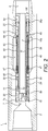
Fig. 2 shows theFig. 1 device in a locked configuration with fluid flowing through the device; -
Fig. 3 shows theFig. 1 device in an unlocked configuration with the bore closed; -
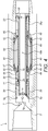
Fig. 4 shows theFig. 1 device in a circulating position with bore closed and the circulation ports open; -
Fig. 5 shows a side view of theFig. 1 device; -
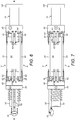
Fig. 6 shows a side view of the counterweight assembly inside the body of theFig. 1 device in configurations shown inFig. 1 ; -
Fig. 7 shows a side view similar toFig. 6 of theFig. 1 device, but rotated through 90°; -
Fig. 8 shows a side view similar toFig. 7 , with the bore of the device closed; -
Fig. 9 shows a side view similar toFig. 6 rotated through 90°, with the bore closed; -
Fig. 10 shows an enlarged view of the lower end ofFig. 2 , illustrating the detail of a balancing mechanism of the device; and -
Figs. 11 ,12 and 13 indicate side and cutaway views of an optional compensation mechanism of theFig. 1 device. - Referring now to
Fig. 1 , a downhole device is typically in the form of a circulation sub 1 incorporating a valve with abody 5 in the form of a tubular having a central axis and having anaxial bore 6 and box and pin connections at either end of the bore enabling thebody 5 to be incorporated within a string of tubulars for deployment in an oil or gas well as is known in the art. Thebore 6 has a central portion 8, athroat 7 located above the central portion 8, and an expansion chamber 9 located within the central portion 8. - The
bore 6 typically houses a tubular member in the form of a tubular 10 extending co-axially with thebore 6, and typically having a narrower diameter than the central portion 8 of the bore, and aflange 10f spacing the tubular 10 from the inner surface of the central portion of the bore 8, thereby forming anannulus 8a between the inner surface of the central portion of the bore 8 and the outer surface of the tubular 10 and asimilar annulus 9a between the tubular 10 and the expansion chamber 9. The tubular 10 typically provides aninner bore 10b passing substantially from thethroat 7 at the upper end to the lower end of thevalve body 5. The inner diameter of the bore 10b of the tubular 10 can be relatively wide, allowing a large bore conduit between the upper and lower ends of the valve 1, and allowing high volumes of fluid to pass at high speed through the valve when the valve is open. The large diametercentral bore 10b of the tubular 10 typically enables normal wireline and coil tubing operations through the centre of the circulation device, without occlusion of thebore 10b. Typically theflange 10f is secured to the inner surface of thebore 6 in thebody 5, restricting axial movement of the tubular 10 in thebody 5, typically by shear pins, or by a ledge, or by other securing mechanism. Typically the expansion chamber 9 can be sealed to prevent debris entering, and can therefore have a sealed volume of clean hydraulic fluid enabling reduced service requirements. - The upper end of the tubular 10 is provided with a closure device typically in the form of a
flapper 15, although other forms of closure device can be used with alternate examples of the invention. In this example, theflapper 15 is pivotally mounted to an upper edge of the side wall of the tubular 10, and can pivotally move around the mounting from the open position shown inFig. 1 , where theflapper 15 does not occlude thebore 10b of the tubular 10, to the closed position shown inFig. 3 , where theflapper 15 has pivoted into a closed position, in which it occludes the bore 10b of the tubular 10. - Above the upper end of the tubular 10 the valve 1 is provided with a
control piston 20 which is typically in the form of a sleeve that is sealed within the central portion of the bore 8 and is axially slidable therein, relative to the tubular 10. The upper end of thecontrol piston 20 has an inlet to admit fluid which is typically no smaller than thethroat 7, so that fluid can pass substantially unhindered from thethroat 7 and through thecontrol piston 20. Adjacent to the opening of the upper end of thecontrol piston 20, the lower surface of the control piston typically has arecess 21 adapted to receive a portion of theflapper 15 in order to lock it in position. Thecontrol piston 20 is typically adapted to slide within the bore between the position inFig. 1 , where theflapper 15 is clear of therecess 21 and is unobstructed by thepiston 20, to the position shown inFig. 2 , where thepiston 20 has moved axially down the central portion of the bore 8, to engage theflapper 15 within therecess 21 and restrict its movement around its pivotal mounting, preventing it from closing thebore 10b of the tubular 10. - The tubular 10 is typically centralised within the
bore 6 of thebody 5 by theflange 10f at the lower end and by a slidingspacer ring 11 at the upper end. Typically, the slidingspacer ring 11 is sealed against the outer surface of the tubular 10, and is typically secured to the upper end of abalancing piston 25, which is typically in the form of a sleeve sealed between the outer surface of the tubular 10 and the inner surface of thebody 5. The lower end of thebalancing piston 25 has flange that is sealed within the central portion of the bore 8 across theannulus 8a. The upper end of thebalancing piston 25 is typically secured, for example by screwing or fixing such as bolts, to the slidingspacer ring 11, so that the slidingspacer ring 11 andbalancing piston 25 move as a unitary component. The slidingspacer ring 11 andbalancing piston 25 are subjected to a biasing force by a resilient device typically in the form of acontrol piston spring 28, which is held in compression between the slidingspacer ring 11 and a fixedblock 30 which is secured to the inner surface of the central portion of the bore 8. Thecontrol piston spring 28 is typically held in compression, and urges the slidingspacer ring 11 andbalancing piston 25 axially upwards, to push thecontrol piston 20 up thebore 6 towards thethroat 7 at the upper end of thebody 5. - The valve 1 has an actuator in the form of a counterweight assembly V to control the state of activation of the
flapper 15. The counterweight assembly V comprises first and second counterweight devices as will now be described. - In this example, the counterweight devices comprise four
plates 40, arranged in opposed pairs at equi-distant spacings around the circumference of the tubular 10. - The
plates 40 typically all have the same mass and dimensions, and their equi-distant spacing in relation to the axis of the valve and in relation to one another around the circumference of thevalve body 5 enables a useful characteristic described below. - The
plates 40 are connected to the valve by a linkage mechanism typically in the form oflink arms 42. Thelink arms 42 are typically provided at the upper and lower ends of eachplate 40, and are typically pivotally connected to the plate allowing pivotal movement between thelink arms 42 and theplate 40. Typically, eachplate 40 has fourlink arms 42, two connected at its lower end, and two connected at its upper end. Typically, one end of eachlink arm 42 is pivotally connected to the plate, and the other end of eachlink arm 42 is pivotally connected to either one of an upper and lower sleeve provided at opposite ends of the actuator V. Therefore, at the lower end of theplates 40, each pair oflink arms 42 pivotally connects to a fixedsleeve 45. Typically, the fixedsleeve 45 is secured to the inner surface of the central portion of the bore 8, optionally by bolts or pins or other fixings, so that it is axially fixed in position within thebore 6. - At the upper end of each
plate 40, theplate 40 is typically connected by a respective pair oflink arms 42 to a slidingsleeve 48 in the same way. The slidingsleeve 42 is free to move axially within thebore 6. Typically, the pivotal connections between theplate 40 and thelink arms 42 are axially spaced from the upper and lower ends of theplate 40, as best shown inFig. 4 . Typically the pivotal connections between theplate 40 and thelink arms 42 are spaced circumferentially around the plate. Typically thelink arms 42 connecting theplates 40 with thecollars plates 40. This can typically be achieved by providing at least two linkarms 42 at each radially spaced location (respective upper and lower ends) of each plate, and connecting the link arms at circumferentially spaced pivot points between theplate 40 and thelink arms 42, thereby resisting rotation of the plate around the long axis, and maintaining stability of theplate 40 as the plate transitions between the first and second configurations. - Therefore, each
plate 40 is connected bylink arms 42 between a single lower fixedsleeve 45 and a singleupper sliding sleeve 48. Thelink arms 42 guide and restrict the movement of theplates 40 in a radial direction within theannulus 9a of the expansion chamber 9. Allplates 40 typically move simultaneously as a result of thelink arms 42 and thesleeves plates 40 are constrained to move radially outwardly from the radially retracted position shown inFig. 2 to the radially extended position shown inFig. 3 in concert with one another, so that, at any particular point, eachplate 40 is the same radial distance away from the outer surface of the tubular 10, and has the same orientation, i.e. parallel to the axis of the tubular 10. Radially outward movement of theplates 40 in this manner therefore draws the slidingsleeve 48 towards the fixedsleeve 45, which cannot move axially within thebody 5, so radial extension of the plates causes the slidingsleeve 48 to slide axially within the central section of the bore 8 down towards the fixedsleeve 48. The force generated from the axial rotation can typically vary with the mass of the plates (which can be varied by adjusting their length, number and circumferential dimensions). In the typical example described with four plates the typical force generated is approximately 3.5 kgf (7.7 lbft) at 150 rpm. Other examples can be devised having a larger number ofplates 40, with a reduced radial travel, and optionally a larger radial dimension of the initial radially retracted first position. Because of the increased centrifugal force resulting from a greater radius of the rotated mass, this enables an increase in the internal dimensions of thebore 10b in the tubular 10, while maintaining a high force from the governor mechanism surrounding the tubular 10, and represents a significant advantage to certain examples of the invention. - As best seen in
Figs 6 to 9 , acontrol rod 50 connects the slidingsleeve 48 with a pivot mechanism operatively connected to theflapper 15. When the slidingsleeve 48 is in the uppermost position as best shown inFig 7 , with theplates 40 in their radially retracted position, thecontrol rod 50 typically pushes the flapper up away from the inlet of the tubular 10, to open the bore of the tubular 10. This is the position adopted inFigs 6 and 7 . When the slidingsleeve 48 moves axially downwards as a result of radial displacement of theplates 40, as best shown inFigs 8 and 9 , thecontrol rod 50 causes theflapper 15 to move to the closed position where it occludes the opening of the upper end of the tubular 10, preventing or at least reducing fluid flow through the tubular 10. In the present example, thecontrol rod 50 typically comprises a pair of rods or bars extending axially generally parallel to the axis of the tubular 10, along its outer surface, but in other examples, the control rod or other actuator transmitting the motive force or signals from the actuator to the closure device can take other forms. - Typically the
control rod 50 moves down to rotate the flapper down to a closed position around a pivot point between theflapper 15 and the upper end of the tubular 10. However, in certain other examples, theflapper 15 andcontrol rod 50 could move in opposite directions, or theflapper 15 could be closed by fluid pressure, and could optionally have a spring mechanism to open it against the force of the fluid pressure. - In use, the circulation sub 1 is run into the hole in the configuration shown in
Fig 1 , with theplates 40 in the radially retracted position, close to the axis of the tubular 10. In this configuration, the slidingsleeve 48 is urged upwardly within thebore 6, so thecontrol rod 50 keeps theflapper 15 open as shown inFigs 1 and6 . The slidingsleeve 48 adopts an axial position close to the fixedblock 30, as best shown inFigs 1 and6 . Theplates 40 are radially collapsed, close to the axis of the sub 1. - The
spring 28 is held in compression between the fixedblock 30, and the slidingspacer ring 11, thereby pushing thecontrol piston 20 towards the top of thebore 6, adjacent to thethroat 7. In this position, theflapper 15 is urged upwards clear of therecess 21 and is held in the open position by thecontrol rod 50. Fluid can pass through thebore 10b in either direction allowing efficient running in. The circulation sub 1 can act as a fluid conduit for supplying drilling fluid or other wellbore fluids to tools situated lower down in the string, beneath the circulation sub 1. Typically, the circulation sub 1 is set relatively high in the string, above the drill bit, and typically above scraping and other cleaning tools, which typically generate particulate debris and cuttings from their drilling, cleaning and scraping operations. - The fluid conduit position is shown in
Fig 2 . In the flowing position shown inFig 2 , theplates 40 are in the radially retracted position as shown inFig 1 , theflapper 15 remains open by virtue of the action of thecontrol rod 50. The only difference betweenFig 1 andFig 2 configurations is that thecontrol piston 20 has slid axially down the bore, away from the throat, to butt against the slidingspacer ring 11, and to compress thespring 28. Thecontrol piston 20 slides as a result of the pressure differential across it within thebore 6. Downward movement of thecontrol piston 20 as shown in the transition fromFig 1 to Fig 2 moves therecess 21 over the upper edge of theflapper 15, thereby preventing closure of theflapper 15 across the opening to the tubular 10. Thebalancing piston 25 typically compensates for any volume changes as a result of the movement of thecontrol piston 20. - In this configuration shown in
Fig 2 , the circulation sub 1 behaves as a simple flow conduit allowing passage of fluid from above the circulation sub 1 through thebore 6, in order to reach various tools located below the circulation sub 1 in the string. For example, in drilling operations, drilling fluid can be pumped at high volumes and high speeds through the circulation sub 1 while in theFig 2 locked configuration, without radial movement of theplates 40, which remain radially collapsed, and without closure of the lockedflapper 15, allowing substantially full bore flow through thelarge bore tubular 10. Activation of theflapper 15 to close the primary flow path through thebore 10b of the tubular 10 is not possible while thecontrol piston 20 is in theFig 2 position, so thevalve body 5 can be rotated at high speeds, for example when conducting rotary drilling operations, at the same time as pumping drilling fluids through thebore 6 at high pressures, volumes and flow rates, or separately, without activating the valve 1. Thecontrol piston 20 is maintained in the locked position axially displaced downwards from thethroat 7 as shown inFig 2 by the pressure differential applied across thepiston 20. While in the locked position, the linkage between theflapper 15 and the slidingsleeve 48 effected by thecontrol rods 50, typically pulls the slidingsleeve 48 upwards in the central portion of the bore 8, thereby keeping theplates 40 in their radially retracted linear position shown inFigs 1 and2 , so even with high speed rotation of the drill string and thebody 5, theplates 40 remain radially close to the axis of thebody 5, and the tool remains in theFig 2 retracted configuration. - The downward sliding of the
control piston 20 pushes the slidingspacer ring 11 downwards through the central portion 8 of thebore 6, to compress thespring 28 against the fixedspacer 30. This also pushes theoptional balancing piston 25 down the bore, as it is secured to the slidingspacer ring 11. - When the circulation sub 1 is to be activated, the pressure across the
control piston 20 is reduced until the force of thespring 28 overcomes the force on thepiston 20 exerted by the pressure differential, and thespring 28 then returns thepiston 20 to the upper position shown inFig 3 , butted against the downwardly facingshoulder 7s of the central portion of the bore 8, adjacent to thethroat 7. In this configuration, theflapper 15 is free from therecess 21 in thecontrol piston 20, as best shown inFig 1 , and is free to move. The fixed and slidingsleeves counterweight spring 47, which is held in compression between the fixed and slidingsleeves Figs 6 and 7 in the absence of any other force. However, when the circulation sub 1 is to be activated in order to divert fluids passing through thebore 6 to tools situated below the circulation sub 1, and instead pump that fluid out through the wall of thebody 5 in order to maintain circulation of particulates within the annulus outside thebody 5, thebody 5 is rotated from the surface, typically at normal drilling speeds of around 100-150 rpm, and the centrifugal force acting on theplates 40 as a result of the rotation causes them to move radially outwards into theannulus 9a of the expansion chamber 9. Because thecontrol piston 20 has moved up, and theflapper 15 is clear of therecess 21, theplates 40 are free to move radially outwards within theannulus 9a, against the force of thespring 47, which is compressed further between the fixed and slidingsleeves Figs 2 and3 . The radial outward movement of theplates 40 effectively pulls the slidingsleeve 48 axially down thebore 6, towards the fixedsleeve 45, which is fixed immovably to thebody 5, as a result of thelink arms 42. As the slidingsleeve 48 is operatively linked to theflapper 15 by virtue of thecontrol rod 50, the radial outward movement of theplates 40 under the centrifugal force resulting from the rotation therefore pulls thecontrol rod 50 axially down thebore 6 in order to close theflapper 15 over the inlet at the upper end of the tubular 10, thereby closing thebore 6 through thebody 5 as best shown inFig 3 . Theflapper 15 is thereby locked in the closed position by the sleeve above it. The closed flapper position also helps to maintain the radially outward configuration of theplates 40. The inner counterweight assembly V inside thebody 5 is then in the configuration shown inFigs 8 and 9 . - With the circulation sub 1 still rotating, the fluid pressure above the
closed flapper 15 then increases, causing thecontrol piston 20 to move down the central portion of the bore 8 from the position shown inFig 3 to the position shown inFig 4 . Typically thecontrol piston 20 has seals above and belowcirculation ports 5p in thebody 5, so that in the running in configuration shown inFig 1 , thecirculation ports 5p are sealed off (typically by double seals) from thebore 6 of the circulation sub 1. The downward movement of thepiston 20 exposescirculation ports 5p passing through the wall of thebody 5 and connecting thebore 6 with the annulus outside thebody 5, and allowing the high pressure fluid to be jetted radially out through theports 5p when the counterweight assembly V is in the configuration shown inFig 4 . In that configuration, theshoulder 20s on the downward facing surface of thecontrol piston 20 presses downwards on the top of theflapper 15, keeping it sealed over the inlet to thebore 10b of the tubular 10, and thereby preventing fluid flow through thebore 10b of the tubular 10, so that substantially all of the fluid passing through thethroat 7 is diverted through thecirculation ports 5p, and is available to jet radially outwards into the annulus, and wash particulates and other debris in the annulus towards the surface. Keeping theflapper 15 pressed down against the inlet at the upper end of the tubular 10 also keeps the slidingsleeve 48 urged axially downwards towards the fixedsleeve 45, thereby keeping theplates 40 in their radially expanded configuration shown inFig 4 , even in the absence of sufficient rotation to generate the central centrifugal force to overcome the force of thespring 47. Typically theflapper 15 has a bypass port (not shown) to allow partial flow through thebore 6 in order to provide some reduced flow to tools below the circulation sub if required. This is an optional feature and is not required in all examples. Thebalance piston 25 typically compensates for the volume changes in the system arising from the movement of the components in this phase. - Once the
flapper 15 is closed and theplates 40 have swung out to the radially extended position within the chamber 9, the fluid pressure acting on thepiston 20 is generally sufficient to keep thecontrol piston 20 pressed down against the top of theflapper 15, keeping theflapper 15 closed and retaining the seal on the tubular 10, and maintaining the circulating position, even in the absence of rotation. Therefore, when circulating with thecontrol piston 20 in its axially downward position exposing the circulation ports, rotation is not necessary, but can be conducted without affecting the circulation operations. - When the circulation operation is completed, and the
circulation ports 5p are to be closed, the pressure on the piston 20 (typically from surface pumps) is reduced until the force of thespring 28 returns the slidingspacer ring 11 andpiston 20 to theFig 1 position. In this configuration, theflapper 15 can still remain closed, with theplates 40 and the radially extended configuration shown inFig 4 if thebody 5 is still subject to sufficient rotation to generate the required centrifugal force to maintain theplates 40 in their radially extended configuration. Therefore, operation of theflapper 15 can optionally be independent of the movement of thecontrol piston 20. However, in most situations, the rotation of thebody 5 at this point will be reduced to reduce the centrifugal force acting on theplates 40, and allow thespring 47 to urge the slidingsleeve 48 axially back up the central portion of the bore 8, and open theflapper 15, so that the configuration of the circulation sub returns to theFig 1 andFig 2 positions, again allowing fluid flow at high velocity and high pressure through thebore 6 across substantially the full bore of the tubular 10. - In certain examples, one optional feature relates to the
balancing piston 25. Examples can be constructed without this component, but in the current example it performs a useful optional function, in that it permits equalisation of the volume of the expansion chamber 9 in the different modes of operation of the device. Thebalancing piston 25 is sealed within theannulus 8a at the lower end of the central portion of the bore 8. Typically the chamber 9 is filled with hydraulic fluid, and is typically sealed. The radially outwards movement of theplates 40 and the downward sliding movement of the slidingsleeve 48 when the circulating sub transitions between theFig 2 andFig 3 positions can typically cause small volume changes in the chamber 9. These can sometimes result in changes in hydraulic pressure of the fluid within the sealed chamber 9, leading to hydraulic lock. These volume changes can optionally be accommodated by sliding of thebalancing piston 25 in order to maintain the volume (and therefore the pressure) of the fluid within the chamber 9 within relatively constant ranges. Thebalancing piston 25 is connected at its upper end to the slidingspacer ring 11, and is generally biased upwardly within the annulus 80 by thespring 28 acting in compression between the fixedspacer 30 and the slidingspacer ring 11. Volumetric changes in the chamber 9 caused by transition of theplates 40 and downward sliding of the slidingsleeve 48 typically cause pressure changes within the hydraulic fluid in the chamber 9 which act on the sealed piston area of thebalancing piston 25. Typically the force of thespring 28 is such that thebalancing piston 25 can typically cause it to compress slightly to pull the slidingspacer ring 11 axially down thebody 5 in order to accommodate the slightly larger volume and increased pressure and balance out any hydraulic locks. Thebalancing piston 25 therefore accommodates changes in volume and pressure of the hydraulic fluid within the chamber 9, and combats the sticking of the slidingsleeve 48 as a result of hydraulic lock. The details of the seals of thebalancing piston 25 are best shown inFig 10 . - Optionally, the
balancing piston 25 has a balance rod mechanism comprising a balance rod extending axially on one side of the bore, and terminating in apiston head 26p which is sealed within the enlarged lower flange of the balance piston 25 (the details of which are best shown inFig 10 ). The upper end of thebalance rod 26 is connected to the slidingsleeve 48, so that downward movement of the slidingsleeve 48 in response to outward movement of theplates 40 in the chamber 9 causes concurrent downward movement of thepiston head 26p sealed within the flange of thebalance piston 25. The linear movement of thebalance rod 26 with the upper slidingsleeve 48 compensates for differences in volume as the sleeve moves and resists hydraulic locking. - A further optional feature that is useful in certain examples of the invention but is not required in others is an orientation compensating mechanism, shown in
Figs 11 ,12 and 13 . - Optionally, the compensating mechanism typically comprises a floating
sleeve 60 freely movable around the outer surface of thespring 47. Thesleeve 60 is typically supported from beneath bycam devices 64 spaced equidistantly around the circumference of the sleeve, which are supported in pivot mountings on the upper surface of the fixedsleeve 45, so that one inner end of thecam device 64 supports the lower surface of thesleeve 60. An outer end of thecam device 64 typically supports apush rod 62 which extends between thecam device 64 and the opposing lower surface of the slidingsleeve 48. When thebody 5 is in a vertical orientation, as shown schematically inFig 11 , thesleeve 60 slides down under gravity to bear on the upper surface of the inner part of thecam device 64, so that the weight of thesleeve 60 is borne by thecam devices 64, which rotate about their pivot mountings in the fixedsleeve 45, and push the outer ends of thecam devices 64 upwards, thereby urging thepush rods 62 axially upwards, to push the slidingsleeve 48 axially away from the fixedsleeve 45. This balancing action only takes effect when thebody 5 is in the vertical position as shown inFig 11 , and thesleeve 60 is pulled under gravity to rest on thecam member 64, and when thebody 5 is in the horizontal position, thesleeve 60 is free to slide axially between the fixed and slidingsleeves cam devices 64, which in turn, do not exert the same axial force on thepush rods 62. Therefore, the balancing mechanism shown inFigs 11 to 13 typically provides additional axial force acting to spread thesleeves body 5 is in the vertical orientation. This is a useful feature which compensates for the weight of theplates 40, which tend, in the vertical position, to fall radially outwards due to gravitational force. Theplates 40 are maintained in their axially retracted position shown inFig 1 by thespring 47, but the balancing action of the compensation mechanism shown inFigs 11 to 13 means that when thebody 5 is in the vertical orientation as shown inFig 11 , the weight of thesleeve 60 counteracts the tendency of theplates 40 to fall outwards, and the force applied by thespring 47 can therefore be reduced. Since the compensating mechanism shown inFigs 11 to 13 only applies any force to the governor mechanism when thebody 5 is in the vertical position, it selectively compensates the activation force between the horizontal and the vertical positions, leading to a more consistent operation of examples of the invention that utilise this feature. - Examples of the invention can, of course, be constructed without necessarily requiring the compensation mechanism shown in
Figs 11 to 13 , but it has the advantage that thespring 47 can be reduced in strength, and the tool can be operated in a wider variety of operational situations. - Examples of the invention provide advantages over earlier systems, in that as the arrangement of counterweight devices is typically balanced around the axis of the body, rotation of the counterweight devices to move them between the first and second configurations is substantially unaffected by the orientation of the axis within the bore hole, enabling the actuator to be used in deviated wells with greater consistency of operation. Examples of the invention therefore facilitate operations at various different angles of deviated well in a consistent manner.
- Examples of the invention typically permit easier activation at normal drill string speeds, for example actuation of the circulation sub described in the examples herein can be achieved at drill string rotation speeds of around 100 to 150 rpm, and in certain examples, the actuator can be maintained in the circulating position by continued flow, with or without continued rotation at the transition speed. The transition speed can typically be adjusted by adjusting the spring strengths and the weights of the plates to suit particular wellbore conditions and different string diameters. Certain examples can easily be reset to the original configuration by stopping flow through the valve with no rotation, or with rotation at speeds below the transition level. Again, this can be adjusted independently by selecting different spring tensions allowing additional adaptability of the device.
- The circulation sub 1 can typically be locked in normal and circulating positions and reset any number of times to original configurations without reliance on dropped balls or other actuation mechanisms requiring reset or recovery of the string.
- In certain examples of the invention, the
plates 40 do not require symmetrical movement, and in one simplified example of the invention, the plates are directly linked at pivot points to the fixedcollar 45, and are linked bylink arms 42 to the slidingcollar 48, so that only one end of the plates 40 (e.g. the upper end) moves radially outwards into the expansion chamber. However, the example shown in the figures with link arms at each end of the plates is advantageous, as it allows a longer travel of the slidingcollar 48. - Typically the tubular 10 is fixed within the
bore 6. Optionally, the tubular 10 can have a ball seat (not shown) for emergency operation in the event that theflapper 15 becomes stuck, allowing a ball to be dropped into the ball seat (not shown) to close thebore 10b of the tubular 10, allowing pressure to build up above the tool to move thecontrol piston 20 down and expose thecirculation ports 5p as described above. - Examples of the invention permit increased bore diameter in circulating subs allowing operation of conventional tools through the bore, while at the same time permitting a decreased outer diameter and typically decreased total length. An increased centrifugal force is permitted at lower rotational speeds, and the balanced governor mechanism increases the stability of the tool and allows simplification of the design.
Claims (15)
- A method of actuating a downhole device, the downhole device having a body (5) with an axis, and having first and second counterweight devices (40) connected on either side of the axis, the method comprising radially moving the counterweight devices (40) between first and second positions by centrifugal force, whereby movement of the counterweight devices (40) causes a change in the activation state of the device, wherein the change in the activation state of the device causes a change in the activation state of a closure device (15) restricting a through bore through a string for the passage of fluid through the string, and wherein the body (5) is incorporated in a string of tools adapted for deployment in a wellbore of an oil or gas well, and creating the centrifugal force to radially move the counterweight devices (40) and change the activation state of the device by rotating the body (5) around the axis, wherein the body (5) is rotated by rotation of the whole string during rotary wellbore operations.
- A method as claimed in claim 1, including restricting the path of movement of each of the counterweight devices (40) between the first and second positions.
- A method as claimed in claim 1 or claim 2, including maintaining a constant orientation of the counterweight devices (40) relative to the axis of the body as the counterweight devices (40) move between the first and second positions.
- A method as claimed in any one of claims 1-3, including controlling the extent and path of radial movement of the counterweight devices (40) between the first and second positions.
- A method as claimed in any one of claims 1-4, wherein the counterweight devices (40) are pivotally connected at axially spaced apart locations to upper and lower sleeves,
- A method as claimed in claim 5, wherein the sleeves surround a central axial tubular comprising the bore of the device, wherein the method includes sliding the sleeves axially along the outer surface of the tubular.
- A method as claimed in claim 6, including performing wireline and coil tubing operations through the bore of the device.
- A method as claimed in claim 6 or claim 7, wherein the counterweight devices (40) are disposed in a sealed chamber (9).
- A method as claimed in any one of claims 1-8, including balancing the volume of a hydraulic fluid within the body (5) of the device between the first and second positions of the counterweight devices (40).
- A method as claimed in any one of claims 1-9, wherein the device comprises a valve having an inlet, a primary outlet and a secondary outlet (5p), and wherein the method includes diverting at least some of the fluid passing through the valve to the secondary outlet rather than to the primary outlet.
- A method as claimed in claim 10, including diverting at least some of the fluid passing through the valve into a circulation pathway which passes through the body of the device.
- A method as claimed in claim 10 or claim 11, wherein the secondary outlet (5p) comprises a port in a side wall of the body (5).
- A method as claimed in any one of claims 1-12, wherein the device comprises a locking mechanism adapted to lock the closure device in open and closed configurations of the closure device, the method including biasing the locking mechanism into the unlocked configuration of the closure device.
- A method as claimed in claim 13, wherein in the open configuration the counterweight devices (40) are locked in a radially collapsed configuration while opening the closure device to permit flow of fluid through the device.
- A method as claimed in claim 13 or claim 14, including locking the closure device (15) in the closed configuration and urging the counterweight devices (40) into a radially expanded configuration by a control rod (50) operatively connected to transfer forces between the closure device and the counterweight devices.
Priority Applications (1)
| Application Number | Priority Date | Filing Date | Title |
|---|---|---|---|
| EP20186799.1A EP3748212B1 (en) | 2012-04-03 | 2013-03-28 | Downhole actuator |
Applications Claiming Priority (2)
| Application Number | Priority Date | Filing Date | Title |
|---|---|---|---|
| GBGB1205954.9A GB201205954D0 (en) | 2012-04-03 | 2012-04-03 | Downhole actuator |
| PCT/GB2013/050844 WO2013150280A2 (en) | 2012-04-03 | 2013-03-28 | Downhole actuator |
Related Child Applications (1)
| Application Number | Title | Priority Date | Filing Date |
|---|---|---|---|
| EP20186799.1A Division EP3748212B1 (en) | 2012-04-03 | 2013-03-28 | Downhole actuator |
Publications (2)
| Publication Number | Publication Date |
|---|---|
| EP2834547A2 EP2834547A2 (en) | 2015-02-11 |
| EP2834547B1 true EP2834547B1 (en) | 2020-07-22 |
Family
ID=46160260
Family Applications (2)
| Application Number | Title | Priority Date | Filing Date |
|---|---|---|---|
| EP20186799.1A Active EP3748212B1 (en) | 2012-04-03 | 2013-03-28 | Downhole actuator |
| EP13718878.5A Active EP2834547B1 (en) | 2012-04-03 | 2013-03-28 | Downhole actuator |
Family Applications Before (1)
| Application Number | Title | Priority Date | Filing Date |
|---|---|---|---|
| EP20186799.1A Active EP3748212B1 (en) | 2012-04-03 | 2013-03-28 | Downhole actuator |
Country Status (4)
| Country | Link |
|---|---|
| US (2) | US9845662B2 (en) |
| EP (2) | EP3748212B1 (en) |
| GB (1) | GB201205954D0 (en) |
| WO (1) | WO2013150280A2 (en) |
Families Citing this family (7)
| Publication number | Priority date | Publication date | Assignee | Title |
|---|---|---|---|---|
| GB2545002B (en) * | 2015-12-03 | 2017-12-20 | Drilltools Ltd | A valve assembly |
| US10450814B2 (en) * | 2016-07-11 | 2019-10-22 | Tenax Energy Solutions, LLC | Single ball activated hydraulic circulating tool |
| WO2019035885A1 (en) * | 2017-08-15 | 2019-02-21 | Schlumberger Technology Corporation | Dual flapper isolation valve |
| US11591869B2 (en) | 2020-02-29 | 2023-02-28 | Tenax Energy Solutions, LLC | Variable flow diverter downhole tool |
| EP4127387B1 (en) | 2020-04-03 | 2024-03-20 | Odfjell Technology Invest Ltd | Hydraulically locked tool |
| GB2610183B (en) | 2021-08-23 | 2024-01-24 | Odfjell Tech Invest Ltd | Controlling a downhole tool |
| AU2023285635A1 (en) * | 2022-06-09 | 2025-01-23 | Advanced Drilling Tools Pty Ltd | A valve system and fluid driven downhole system and method |
Citations (1)
| Publication number | Priority date | Publication date | Assignee | Title |
|---|---|---|---|---|
| US20110266001A1 (en) * | 2010-04-29 | 2011-11-03 | Halliburton Energy Services, Inc. | Method and apparatus for controlling fluid flow using movable flow diverter assembly |
Family Cites Families (15)
| Publication number | Priority date | Publication date | Assignee | Title |
|---|---|---|---|---|
| US2879032A (en) * | 1954-12-10 | 1959-03-24 | Shell Dev | Hydraulic turbine with by-pass valve |
| US2963099A (en) * | 1957-07-18 | 1960-12-06 | Jr Sabin J Gianelloni | Turbodrill |
| FR2145060A5 (en) * | 1971-07-07 | 1973-02-16 | Inst Francais Du Petrole | |
| US3767332A (en) * | 1971-08-16 | 1973-10-23 | Black & Decker Mfg Co | Speed control and cut-off device |
| FR2169708B1 (en) * | 1971-12-17 | 1974-09-06 | Inst Francais Du Petrole | |
| US3874634A (en) * | 1973-11-07 | 1975-04-01 | Otis Eng Co | Well safety valve system |
| US3967680A (en) * | 1974-08-01 | 1976-07-06 | Texas Dynamatics, Inc. | Method and apparatus for actuating a downhole device carried by a pipe string |
| DE2821074A1 (en) * | 1978-05-13 | 1979-11-22 | Bosch Gmbh Robert | COMPRESSED AIR TOOL WITH ROTATING MOTOR |
| US4467526A (en) * | 1982-06-16 | 1984-08-28 | Techdel International Inc. | Inclination instrument |
| GB8509326D0 (en) * | 1985-04-11 | 1985-05-15 | Drexel Equipment Ltd | Centralizing device |
| US4721172A (en) | 1985-11-22 | 1988-01-26 | Amoco Corporation | Apparatus for controlling the force applied to a drill bit while drilling |
| GB0029531D0 (en) * | 2000-12-04 | 2001-01-17 | Rotech Holdings Ltd | Speed govenor |
| US20050211471A1 (en) * | 2004-03-29 | 2005-09-29 | Cdx Gas, Llc | System and method for controlling drill motor rotational speed |
| WO2011000020A1 (en) | 2009-06-12 | 2011-01-06 | Sbc Research Pty Ltd | Enhanced method of detection |
| GB0914258D0 (en) | 2009-08-14 | 2009-09-30 | Titan Torque Services Ltd | Actuator and method |
-
2012
- 2012-04-03 GB GBGB1205954.9A patent/GB201205954D0/en not_active Ceased
-
2013
- 2013-03-28 EP EP20186799.1A patent/EP3748212B1/en active Active
- 2013-03-28 EP EP13718878.5A patent/EP2834547B1/en active Active
- 2013-03-28 US US14/389,928 patent/US9845662B2/en active Active
- 2013-03-28 WO PCT/GB2013/050844 patent/WO2013150280A2/en not_active Ceased
-
2017
- 2017-11-09 US US15/808,173 patent/US10472930B2/en active Active
Patent Citations (1)
| Publication number | Priority date | Publication date | Assignee | Title |
|---|---|---|---|---|
| US20110266001A1 (en) * | 2010-04-29 | 2011-11-03 | Halliburton Energy Services, Inc. | Method and apparatus for controlling fluid flow using movable flow diverter assembly |
Also Published As
| Publication number | Publication date |
|---|---|
| US20150068763A1 (en) | 2015-03-12 |
| EP2834547A2 (en) | 2015-02-11 |
| WO2013150280A2 (en) | 2013-10-10 |
| GB201205954D0 (en) | 2012-05-16 |
| US10472930B2 (en) | 2019-11-12 |
| EP3748212B1 (en) | 2025-07-23 |
| US9845662B2 (en) | 2017-12-19 |
| US20180073330A1 (en) | 2018-03-15 |
| WO2013150280A3 (en) | 2014-04-03 |
| EP3748212A1 (en) | 2020-12-09 |
Similar Documents
| Publication | Publication Date | Title |
|---|---|---|
| US10472930B2 (en) | Downhole actuator | |
| US9255466B2 (en) | Liner hanger fluid diverter tool and related methods | |
| US10480290B2 (en) | Controller for downhole tool | |
| US12000228B2 (en) | Flow diversion valve for downtool tool assembly | |
| US9587462B2 (en) | Safety valve system for cable deployed electric submersible pump | |
| AU783421B2 (en) | Float valve assembly for downhole tubulars | |
| US9267331B2 (en) | Expandable reamers and methods of using expandable reamers | |
| US11867013B2 (en) | Flow diversion valve for downhole tool assembly | |
| NO20161515A1 (en) | Setting tool with pressure shock absorber | |
| US9650863B2 (en) | Safety valve system for cable deployed electric submersible pump | |
| EP2971473B1 (en) | Drill string check valve | |
| NO20231275A1 (en) | Venturi activated downhole torque limiter | |
| US9822607B2 (en) | Control line damper for valves | |
| CN117280108A (en) | flow control system | |
| US20220282593A1 (en) | Circulation valve | |
| CA3140576C (en) | Circulation valve | |
| AU2012384917B2 (en) | Control line damper for valves |
Legal Events
| Date | Code | Title | Description |
|---|---|---|---|
| PUAI | Public reference made under article 153(3) epc to a published international application that has entered the european phase |
Free format text: ORIGINAL CODE: 0009012 |
|
| 17P | Request for examination filed |
Effective date: 20141001 |
|
| AK | Designated contracting states |
Kind code of ref document: A2 Designated state(s): AL AT BE BG CH CY CZ DE DK EE ES FI FR GB GR HR HU IE IS IT LI LT LU LV MC MK MT NL NO PL PT RO RS SE SI SK SM TR |
|
| AX | Request for extension of the european patent |
Extension state: BA ME |
|
| RAP1 | Party data changed (applicant data changed or rights of an application transferred) |
Owner name: CFF TECHNOLOGIES LIMITED |
|
| DAX | Request for extension of the european patent (deleted) | ||
| RIN1 | Information on inventor provided before grant (corrected) |
Inventor name: YOUNGER, RAE ANDREW Inventor name: ROTHNIE, STUART THOMAS Inventor name: JEPP, BRUCE THORNTON Inventor name: GASKIN, KEITH SCOTT |
|
| STAA | Information on the status of an ep patent application or granted ep patent |
Free format text: STATUS: EXAMINATION IS IN PROGRESS |
|
| 17Q | First examination report despatched |
Effective date: 20180129 |
|
| GRAP | Despatch of communication of intention to grant a patent |
Free format text: ORIGINAL CODE: EPIDOSNIGR1 |
|
| STAA | Information on the status of an ep patent application or granted ep patent |
Free format text: STATUS: GRANT OF PATENT IS INTENDED |
|
| INTG | Intention to grant announced |
Effective date: 20200228 |
|
| GRAS | Grant fee paid |
Free format text: ORIGINAL CODE: EPIDOSNIGR3 |
|
| GRAA | (expected) grant |
Free format text: ORIGINAL CODE: 0009210 |
|
| STAA | Information on the status of an ep patent application or granted ep patent |
Free format text: STATUS: THE PATENT HAS BEEN GRANTED |
|
| AK | Designated contracting states |
Kind code of ref document: B1 Designated state(s): AL AT BE BG CH CY CZ DE DK EE ES FI FR GB GR HR HU IE IS IT LI LT LU LV MC MK MT NL NO PL PT RO RS SE SI SK SM TR |
|
| REG | Reference to a national code |
Ref country code: GB Ref legal event code: FG4D |
|
| REG | Reference to a national code |
Ref country code: CH Ref legal event code: EP |
|
| REG | Reference to a national code |
Ref country code: DE Ref legal event code: R096 Ref document number: 602013070890 Country of ref document: DE |
|
| REG | Reference to a national code |
Ref country code: AT Ref legal event code: REF Ref document number: 1293713 Country of ref document: AT Kind code of ref document: T Effective date: 20200815 |
|
| REG | Reference to a national code |
Ref country code: IE Ref legal event code: FG4D |
|
| REG | Reference to a national code |
Ref country code: LT Ref legal event code: MG4D |
|
| REG | Reference to a national code |
Ref country code: AT Ref legal event code: MK05 Ref document number: 1293713 Country of ref document: AT Kind code of ref document: T Effective date: 20200722 |
|
| PG25 | Lapsed in a contracting state [announced via postgrant information from national office to epo] |
Ref country code: ES Free format text: LAPSE BECAUSE OF FAILURE TO SUBMIT A TRANSLATION OF THE DESCRIPTION OR TO PAY THE FEE WITHIN THE PRESCRIBED TIME-LIMIT Effective date: 20200722 Ref country code: BG Free format text: LAPSE BECAUSE OF FAILURE TO SUBMIT A TRANSLATION OF THE DESCRIPTION OR TO PAY THE FEE WITHIN THE PRESCRIBED TIME-LIMIT Effective date: 20201022 Ref country code: GR Free format text: LAPSE BECAUSE OF FAILURE TO SUBMIT A TRANSLATION OF THE DESCRIPTION OR TO PAY THE FEE WITHIN THE PRESCRIBED TIME-LIMIT Effective date: 20201023 Ref country code: NO Free format text: LAPSE BECAUSE OF FAILURE TO SUBMIT A TRANSLATION OF THE DESCRIPTION OR TO PAY THE FEE WITHIN THE PRESCRIBED TIME-LIMIT Effective date: 20201022 Ref country code: AT Free format text: LAPSE BECAUSE OF FAILURE TO SUBMIT A TRANSLATION OF THE DESCRIPTION OR TO PAY THE FEE WITHIN THE PRESCRIBED TIME-LIMIT Effective date: 20200722 Ref country code: PT Free format text: LAPSE BECAUSE OF FAILURE TO SUBMIT A TRANSLATION OF THE DESCRIPTION OR TO PAY THE FEE WITHIN THE PRESCRIBED TIME-LIMIT Effective date: 20201123 Ref country code: LT Free format text: LAPSE BECAUSE OF FAILURE TO SUBMIT A TRANSLATION OF THE DESCRIPTION OR TO PAY THE FEE WITHIN THE PRESCRIBED TIME-LIMIT Effective date: 20200722 Ref country code: FI Free format text: LAPSE BECAUSE OF FAILURE TO SUBMIT A TRANSLATION OF THE DESCRIPTION OR TO PAY THE FEE WITHIN THE PRESCRIBED TIME-LIMIT Effective date: 20200722 Ref country code: SE Free format text: LAPSE BECAUSE OF FAILURE TO SUBMIT A TRANSLATION OF THE DESCRIPTION OR TO PAY THE FEE WITHIN THE PRESCRIBED TIME-LIMIT Effective date: 20200722 Ref country code: HR Free format text: LAPSE BECAUSE OF FAILURE TO SUBMIT A TRANSLATION OF THE DESCRIPTION OR TO PAY THE FEE WITHIN THE PRESCRIBED TIME-LIMIT Effective date: 20200722 |
|
| PG25 | Lapsed in a contracting state [announced via postgrant information from national office to epo] |
Ref country code: LV Free format text: LAPSE BECAUSE OF FAILURE TO SUBMIT A TRANSLATION OF THE DESCRIPTION OR TO PAY THE FEE WITHIN THE PRESCRIBED TIME-LIMIT Effective date: 20200722 Ref country code: PL Free format text: LAPSE BECAUSE OF FAILURE TO SUBMIT A TRANSLATION OF THE DESCRIPTION OR TO PAY THE FEE WITHIN THE PRESCRIBED TIME-LIMIT Effective date: 20200722 Ref country code: RS Free format text: LAPSE BECAUSE OF FAILURE TO SUBMIT A TRANSLATION OF THE DESCRIPTION OR TO PAY THE FEE WITHIN THE PRESCRIBED TIME-LIMIT Effective date: 20200722 Ref country code: IS Free format text: LAPSE BECAUSE OF FAILURE TO SUBMIT A TRANSLATION OF THE DESCRIPTION OR TO PAY THE FEE WITHIN THE PRESCRIBED TIME-LIMIT Effective date: 20201122 |
|
| PG25 | Lapsed in a contracting state [announced via postgrant information from national office to epo] |
Ref country code: NL Free format text: LAPSE BECAUSE OF FAILURE TO SUBMIT A TRANSLATION OF THE DESCRIPTION OR TO PAY THE FEE WITHIN THE PRESCRIBED TIME-LIMIT Effective date: 20200722 |
|
| REG | Reference to a national code |
Ref country code: DE Ref legal event code: R097 Ref document number: 602013070890 Country of ref document: DE |
|
| PG25 | Lapsed in a contracting state [announced via postgrant information from national office to epo] |
Ref country code: IT Free format text: LAPSE BECAUSE OF FAILURE TO SUBMIT A TRANSLATION OF THE DESCRIPTION OR TO PAY THE FEE WITHIN THE PRESCRIBED TIME-LIMIT Effective date: 20200722 Ref country code: DK Free format text: LAPSE BECAUSE OF FAILURE TO SUBMIT A TRANSLATION OF THE DESCRIPTION OR TO PAY THE FEE WITHIN THE PRESCRIBED TIME-LIMIT Effective date: 20200722 Ref country code: EE Free format text: LAPSE BECAUSE OF FAILURE TO SUBMIT A TRANSLATION OF THE DESCRIPTION OR TO PAY THE FEE WITHIN THE PRESCRIBED TIME-LIMIT Effective date: 20200722 Ref country code: CZ Free format text: LAPSE BECAUSE OF FAILURE TO SUBMIT A TRANSLATION OF THE DESCRIPTION OR TO PAY THE FEE WITHIN THE PRESCRIBED TIME-LIMIT Effective date: 20200722 Ref country code: SM Free format text: LAPSE BECAUSE OF FAILURE TO SUBMIT A TRANSLATION OF THE DESCRIPTION OR TO PAY THE FEE WITHIN THE PRESCRIBED TIME-LIMIT Effective date: 20200722 Ref country code: RO Free format text: LAPSE BECAUSE OF FAILURE TO SUBMIT A TRANSLATION OF THE DESCRIPTION OR TO PAY THE FEE WITHIN THE PRESCRIBED TIME-LIMIT Effective date: 20200722 |
|
| PLBE | No opposition filed within time limit |
Free format text: ORIGINAL CODE: 0009261 |
|
| STAA | Information on the status of an ep patent application or granted ep patent |
Free format text: STATUS: NO OPPOSITION FILED WITHIN TIME LIMIT |
|
| PG25 | Lapsed in a contracting state [announced via postgrant information from national office to epo] |
Ref country code: AL Free format text: LAPSE BECAUSE OF FAILURE TO SUBMIT A TRANSLATION OF THE DESCRIPTION OR TO PAY THE FEE WITHIN THE PRESCRIBED TIME-LIMIT Effective date: 20200722 |
|
| 26N | No opposition filed |
Effective date: 20210423 |
|
| PG25 | Lapsed in a contracting state [announced via postgrant information from national office to epo] |
Ref country code: SK Free format text: LAPSE BECAUSE OF FAILURE TO SUBMIT A TRANSLATION OF THE DESCRIPTION OR TO PAY THE FEE WITHIN THE PRESCRIBED TIME-LIMIT Effective date: 20200722 |
|
| PG25 | Lapsed in a contracting state [announced via postgrant information from national office to epo] |
Ref country code: SI Free format text: LAPSE BECAUSE OF FAILURE TO SUBMIT A TRANSLATION OF THE DESCRIPTION OR TO PAY THE FEE WITHIN THE PRESCRIBED TIME-LIMIT Effective date: 20200722 |
|
| REG | Reference to a national code |
Ref country code: DE Ref legal event code: R119 Ref document number: 602013070890 Country of ref document: DE |
|
| REG | Reference to a national code |
Ref country code: NL Ref legal event code: MP Effective date: 20200722 |
|
| PG25 | Lapsed in a contracting state [announced via postgrant information from national office to epo] |
Ref country code: MC Free format text: LAPSE BECAUSE OF FAILURE TO SUBMIT A TRANSLATION OF THE DESCRIPTION OR TO PAY THE FEE WITHIN THE PRESCRIBED TIME-LIMIT Effective date: 20200722 |
|
| REG | Reference to a national code |
Ref country code: CH Ref legal event code: PL |
|
| REG | Reference to a national code |
Ref country code: BE Ref legal event code: MM Effective date: 20210331 |
|
| PG25 | Lapsed in a contracting state [announced via postgrant information from national office to epo] |
Ref country code: CH Free format text: LAPSE BECAUSE OF NON-PAYMENT OF DUE FEES Effective date: 20210331 Ref country code: LU Free format text: LAPSE BECAUSE OF NON-PAYMENT OF DUE FEES Effective date: 20210328 Ref country code: LI Free format text: LAPSE BECAUSE OF NON-PAYMENT OF DUE FEES Effective date: 20210331 Ref country code: FR Free format text: LAPSE BECAUSE OF NON-PAYMENT OF DUE FEES Effective date: 20210331 Ref country code: IE Free format text: LAPSE BECAUSE OF NON-PAYMENT OF DUE FEES Effective date: 20210328 Ref country code: DE Free format text: LAPSE BECAUSE OF NON-PAYMENT OF DUE FEES Effective date: 20211001 |
|
| PG25 | Lapsed in a contracting state [announced via postgrant information from national office to epo] |
Ref country code: BE Free format text: LAPSE BECAUSE OF NON-PAYMENT OF DUE FEES Effective date: 20210331 |
|
| PG25 | Lapsed in a contracting state [announced via postgrant information from national office to epo] |
Ref country code: HU Free format text: LAPSE BECAUSE OF FAILURE TO SUBMIT A TRANSLATION OF THE DESCRIPTION OR TO PAY THE FEE WITHIN THE PRESCRIBED TIME-LIMIT; INVALID AB INITIO Effective date: 20130328 |
|
| PG25 | Lapsed in a contracting state [announced via postgrant information from national office to epo] |
Ref country code: CY Free format text: LAPSE BECAUSE OF FAILURE TO SUBMIT A TRANSLATION OF THE DESCRIPTION OR TO PAY THE FEE WITHIN THE PRESCRIBED TIME-LIMIT Effective date: 20200722 |
|
| PG25 | Lapsed in a contracting state [announced via postgrant information from national office to epo] |
Ref country code: MK Free format text: LAPSE BECAUSE OF FAILURE TO SUBMIT A TRANSLATION OF THE DESCRIPTION OR TO PAY THE FEE WITHIN THE PRESCRIBED TIME-LIMIT Effective date: 20200722 |
|
| PG25 | Lapsed in a contracting state [announced via postgrant information from national office to epo] |
Ref country code: TR Free format text: LAPSE BECAUSE OF FAILURE TO SUBMIT A TRANSLATION OF THE DESCRIPTION OR TO PAY THE FEE WITHIN THE PRESCRIBED TIME-LIMIT Effective date: 20200722 |
|
| PG25 | Lapsed in a contracting state [announced via postgrant information from national office to epo] |
Ref country code: MT Free format text: LAPSE BECAUSE OF FAILURE TO SUBMIT A TRANSLATION OF THE DESCRIPTION OR TO PAY THE FEE WITHIN THE PRESCRIBED TIME-LIMIT Effective date: 20200722 |
|
| PGFP | Annual fee paid to national office [announced via postgrant information from national office to epo] |
Ref country code: GB Payment date: 20260330 Year of fee payment: 14 |