EP2833841B1 - Prosthetic ankle components - Google Patents
Prosthetic ankle components Download PDFInfo
- Publication number
- EP2833841B1 EP2833841B1 EP13719138.3A EP13719138A EP2833841B1 EP 2833841 B1 EP2833841 B1 EP 2833841B1 EP 13719138 A EP13719138 A EP 13719138A EP 2833841 B1 EP2833841 B1 EP 2833841B1
- Authority
- EP
- European Patent Office
- Prior art keywords
- prosthetic ankle
- component
- bearing surface
- components
- prosthetic
- Prior art date
- Legal status (The legal status is an assumption and is not a legal conclusion. Google has not performed a legal analysis and makes no representation as to the accuracy of the status listed.)
- Active
Links
Images



Classifications
-
- A—HUMAN NECESSITIES
- A61—MEDICAL OR VETERINARY SCIENCE; HYGIENE
- A61F—FILTERS IMPLANTABLE INTO BLOOD VESSELS; PROSTHESES; DEVICES PROVIDING PATENCY TO, OR PREVENTING COLLAPSING OF, TUBULAR STRUCTURES OF THE BODY, e.g. STENTS; ORTHOPAEDIC, NURSING OR CONTRACEPTIVE DEVICES; FOMENTATION; TREATMENT OR PROTECTION OF EYES OR EARS; BANDAGES, DRESSINGS OR ABSORBENT PADS; FIRST-AID KITS
- A61F2/00—Filters implantable into blood vessels; Prostheses, i.e. artificial substitutes or replacements for parts of the body; Appliances for connecting them with the body; Devices providing patency to, or preventing collapsing of, tubular structures of the body, e.g. stents
- A61F2/02—Prostheses implantable into the body
- A61F2/30—Joints
- A61F2/42—Joints for wrists or ankles; for hands, e.g. fingers; for feet, e.g. toes
- A61F2/4202—Joints for wrists or ankles; for hands, e.g. fingers; for feet, e.g. toes for ankles
-
- A—HUMAN NECESSITIES
- A61—MEDICAL OR VETERINARY SCIENCE; HYGIENE
- A61F—FILTERS IMPLANTABLE INTO BLOOD VESSELS; PROSTHESES; DEVICES PROVIDING PATENCY TO, OR PREVENTING COLLAPSING OF, TUBULAR STRUCTURES OF THE BODY, e.g. STENTS; ORTHOPAEDIC, NURSING OR CONTRACEPTIVE DEVICES; FOMENTATION; TREATMENT OR PROTECTION OF EYES OR EARS; BANDAGES, DRESSINGS OR ABSORBENT PADS; FIRST-AID KITS
- A61F2/00—Filters implantable into blood vessels; Prostheses, i.e. artificial substitutes or replacements for parts of the body; Appliances for connecting them with the body; Devices providing patency to, or preventing collapsing of, tubular structures of the body, e.g. stents
- A61F2/50—Prostheses not implantable in the body
- A61F2/60—Artificial legs or feet or parts thereof
- A61F2/66—Feet; Ankle joints
- A61F2/6607—Ankle joints
-
- A—HUMAN NECESSITIES
- A61—MEDICAL OR VETERINARY SCIENCE; HYGIENE
- A61F—FILTERS IMPLANTABLE INTO BLOOD VESSELS; PROSTHESES; DEVICES PROVIDING PATENCY TO, OR PREVENTING COLLAPSING OF, TUBULAR STRUCTURES OF THE BODY, e.g. STENTS; ORTHOPAEDIC, NURSING OR CONTRACEPTIVE DEVICES; FOMENTATION; TREATMENT OR PROTECTION OF EYES OR EARS; BANDAGES, DRESSINGS OR ABSORBENT PADS; FIRST-AID KITS
- A61F2/00—Filters implantable into blood vessels; Prostheses, i.e. artificial substitutes or replacements for parts of the body; Appliances for connecting them with the body; Devices providing patency to, or preventing collapsing of, tubular structures of the body, e.g. stents
- A61F2/02—Prostheses implantable into the body
- A61F2/30—Joints
- A61F2002/30001—Additional features of subject-matter classified in A61F2/28, A61F2/30 and subgroups thereof
- A61F2002/30108—Shapes
- A61F2002/3011—Cross-sections or two-dimensional shapes
- A61F2002/30159—Concave polygonal shapes
- A61F2002/30168—L-shaped
-
- A—HUMAN NECESSITIES
- A61—MEDICAL OR VETERINARY SCIENCE; HYGIENE
- A61F—FILTERS IMPLANTABLE INTO BLOOD VESSELS; PROSTHESES; DEVICES PROVIDING PATENCY TO, OR PREVENTING COLLAPSING OF, TUBULAR STRUCTURES OF THE BODY, e.g. STENTS; ORTHOPAEDIC, NURSING OR CONTRACEPTIVE DEVICES; FOMENTATION; TREATMENT OR PROTECTION OF EYES OR EARS; BANDAGES, DRESSINGS OR ABSORBENT PADS; FIRST-AID KITS
- A61F2/00—Filters implantable into blood vessels; Prostheses, i.e. artificial substitutes or replacements for parts of the body; Appliances for connecting them with the body; Devices providing patency to, or preventing collapsing of, tubular structures of the body, e.g. stents
- A61F2/02—Prostheses implantable into the body
- A61F2/30—Joints
- A61F2002/30001—Additional features of subject-matter classified in A61F2/28, A61F2/30 and subgroups thereof
- A61F2002/30108—Shapes
- A61F2002/3011—Cross-sections or two-dimensional shapes
- A61F2002/30159—Concave polygonal shapes
- A61F2002/30172—T-shaped
-
- A—HUMAN NECESSITIES
- A61—MEDICAL OR VETERINARY SCIENCE; HYGIENE
- A61F—FILTERS IMPLANTABLE INTO BLOOD VESSELS; PROSTHESES; DEVICES PROVIDING PATENCY TO, OR PREVENTING COLLAPSING OF, TUBULAR STRUCTURES OF THE BODY, e.g. STENTS; ORTHOPAEDIC, NURSING OR CONTRACEPTIVE DEVICES; FOMENTATION; TREATMENT OR PROTECTION OF EYES OR EARS; BANDAGES, DRESSINGS OR ABSORBENT PADS; FIRST-AID KITS
- A61F2/00—Filters implantable into blood vessels; Prostheses, i.e. artificial substitutes or replacements for parts of the body; Appliances for connecting them with the body; Devices providing patency to, or preventing collapsing of, tubular structures of the body, e.g. stents
- A61F2/02—Prostheses implantable into the body
- A61F2/30—Joints
- A61F2002/30001—Additional features of subject-matter classified in A61F2/28, A61F2/30 and subgroups thereof
- A61F2002/30108—Shapes
- A61F2002/30199—Three-dimensional shapes
- A61F2002/30299—Three-dimensional shapes umbrella-shaped or mushroom-shaped
-
- A—HUMAN NECESSITIES
- A61—MEDICAL OR VETERINARY SCIENCE; HYGIENE
- A61F—FILTERS IMPLANTABLE INTO BLOOD VESSELS; PROSTHESES; DEVICES PROVIDING PATENCY TO, OR PREVENTING COLLAPSING OF, TUBULAR STRUCTURES OF THE BODY, e.g. STENTS; ORTHOPAEDIC, NURSING OR CONTRACEPTIVE DEVICES; FOMENTATION; TREATMENT OR PROTECTION OF EYES OR EARS; BANDAGES, DRESSINGS OR ABSORBENT PADS; FIRST-AID KITS
- A61F2/00—Filters implantable into blood vessels; Prostheses, i.e. artificial substitutes or replacements for parts of the body; Appliances for connecting them with the body; Devices providing patency to, or preventing collapsing of, tubular structures of the body, e.g. stents
- A61F2/02—Prostheses implantable into the body
- A61F2/30—Joints
- A61F2002/30001—Additional features of subject-matter classified in A61F2/28, A61F2/30 and subgroups thereof
- A61F2002/30316—The prosthesis having different structural features at different locations within the same prosthesis; Connections between prosthetic parts; Special structural features of bone or joint prostheses not otherwise provided for
- A61F2002/30329—Connections or couplings between prosthetic parts, e.g. between modular parts; Connecting elements
- A61F2002/30331—Connections or couplings between prosthetic parts, e.g. between modular parts; Connecting elements made by longitudinally pushing a protrusion into a complementarily-shaped recess, e.g. held by friction fit
-
- A—HUMAN NECESSITIES
- A61—MEDICAL OR VETERINARY SCIENCE; HYGIENE
- A61F—FILTERS IMPLANTABLE INTO BLOOD VESSELS; PROSTHESES; DEVICES PROVIDING PATENCY TO, OR PREVENTING COLLAPSING OF, TUBULAR STRUCTURES OF THE BODY, e.g. STENTS; ORTHOPAEDIC, NURSING OR CONTRACEPTIVE DEVICES; FOMENTATION; TREATMENT OR PROTECTION OF EYES OR EARS; BANDAGES, DRESSINGS OR ABSORBENT PADS; FIRST-AID KITS
- A61F2/00—Filters implantable into blood vessels; Prostheses, i.e. artificial substitutes or replacements for parts of the body; Appliances for connecting them with the body; Devices providing patency to, or preventing collapsing of, tubular structures of the body, e.g. stents
- A61F2/02—Prostheses implantable into the body
- A61F2/30—Joints
- A61F2002/30001—Additional features of subject-matter classified in A61F2/28, A61F2/30 and subgroups thereof
- A61F2002/30316—The prosthesis having different structural features at different locations within the same prosthesis; Connections between prosthetic parts; Special structural features of bone or joint prostheses not otherwise provided for
- A61F2002/30329—Connections or couplings between prosthetic parts, e.g. between modular parts; Connecting elements
- A61F2002/30331—Connections or couplings between prosthetic parts, e.g. between modular parts; Connecting elements made by longitudinally pushing a protrusion into a complementarily-shaped recess, e.g. held by friction fit
- A61F2002/30362—Connections or couplings between prosthetic parts, e.g. between modular parts; Connecting elements made by longitudinally pushing a protrusion into a complementarily-shaped recess, e.g. held by friction fit with possibility of relative movement between the protrusion and the recess
- A61F2002/30364—Rotation about the common longitudinal axis
-
- A—HUMAN NECESSITIES
- A61—MEDICAL OR VETERINARY SCIENCE; HYGIENE
- A61F—FILTERS IMPLANTABLE INTO BLOOD VESSELS; PROSTHESES; DEVICES PROVIDING PATENCY TO, OR PREVENTING COLLAPSING OF, TUBULAR STRUCTURES OF THE BODY, e.g. STENTS; ORTHOPAEDIC, NURSING OR CONTRACEPTIVE DEVICES; FOMENTATION; TREATMENT OR PROTECTION OF EYES OR EARS; BANDAGES, DRESSINGS OR ABSORBENT PADS; FIRST-AID KITS
- A61F2/00—Filters implantable into blood vessels; Prostheses, i.e. artificial substitutes or replacements for parts of the body; Appliances for connecting them with the body; Devices providing patency to, or preventing collapsing of, tubular structures of the body, e.g. stents
- A61F2/02—Prostheses implantable into the body
- A61F2/30—Joints
- A61F2002/30001—Additional features of subject-matter classified in A61F2/28, A61F2/30 and subgroups thereof
- A61F2002/30316—The prosthesis having different structural features at different locations within the same prosthesis; Connections between prosthetic parts; Special structural features of bone or joint prostheses not otherwise provided for
- A61F2002/30329—Connections or couplings between prosthetic parts, e.g. between modular parts; Connecting elements
- A61F2002/30383—Connections or couplings between prosthetic parts, e.g. between modular parts; Connecting elements made by laterally inserting a protrusion, e.g. a rib into a complementarily-shaped groove
- A61F2002/30387—Dovetail connection
-
- A—HUMAN NECESSITIES
- A61—MEDICAL OR VETERINARY SCIENCE; HYGIENE
- A61F—FILTERS IMPLANTABLE INTO BLOOD VESSELS; PROSTHESES; DEVICES PROVIDING PATENCY TO, OR PREVENTING COLLAPSING OF, TUBULAR STRUCTURES OF THE BODY, e.g. STENTS; ORTHOPAEDIC, NURSING OR CONTRACEPTIVE DEVICES; FOMENTATION; TREATMENT OR PROTECTION OF EYES OR EARS; BANDAGES, DRESSINGS OR ABSORBENT PADS; FIRST-AID KITS
- A61F2/00—Filters implantable into blood vessels; Prostheses, i.e. artificial substitutes or replacements for parts of the body; Appliances for connecting them with the body; Devices providing patency to, or preventing collapsing of, tubular structures of the body, e.g. stents
- A61F2/02—Prostheses implantable into the body
- A61F2/30—Joints
- A61F2002/30001—Additional features of subject-matter classified in A61F2/28, A61F2/30 and subgroups thereof
- A61F2002/30316—The prosthesis having different structural features at different locations within the same prosthesis; Connections between prosthetic parts; Special structural features of bone or joint prostheses not otherwise provided for
- A61F2002/30329—Connections or couplings between prosthetic parts, e.g. between modular parts; Connecting elements
- A61F2002/30383—Connections or couplings between prosthetic parts, e.g. between modular parts; Connecting elements made by laterally inserting a protrusion, e.g. a rib into a complementarily-shaped groove
- A61F2002/3039—Connections or couplings between prosthetic parts, e.g. between modular parts; Connecting elements made by laterally inserting a protrusion, e.g. a rib into a complementarily-shaped groove with possibility of relative movement of the rib within the groove
-
- A—HUMAN NECESSITIES
- A61—MEDICAL OR VETERINARY SCIENCE; HYGIENE
- A61F—FILTERS IMPLANTABLE INTO BLOOD VESSELS; PROSTHESES; DEVICES PROVIDING PATENCY TO, OR PREVENTING COLLAPSING OF, TUBULAR STRUCTURES OF THE BODY, e.g. STENTS; ORTHOPAEDIC, NURSING OR CONTRACEPTIVE DEVICES; FOMENTATION; TREATMENT OR PROTECTION OF EYES OR EARS; BANDAGES, DRESSINGS OR ABSORBENT PADS; FIRST-AID KITS
- A61F2/00—Filters implantable into blood vessels; Prostheses, i.e. artificial substitutes or replacements for parts of the body; Appliances for connecting them with the body; Devices providing patency to, or preventing collapsing of, tubular structures of the body, e.g. stents
- A61F2/02—Prostheses implantable into the body
- A61F2/30—Joints
- A61F2002/30001—Additional features of subject-matter classified in A61F2/28, A61F2/30 and subgroups thereof
- A61F2002/30316—The prosthesis having different structural features at different locations within the same prosthesis; Connections between prosthetic parts; Special structural features of bone or joint prostheses not otherwise provided for
- A61F2002/30329—Connections or couplings between prosthetic parts, e.g. between modular parts; Connecting elements
- A61F2002/30383—Connections or couplings between prosthetic parts, e.g. between modular parts; Connecting elements made by laterally inserting a protrusion, e.g. a rib into a complementarily-shaped groove
- A61F2002/3039—Connections or couplings between prosthetic parts, e.g. between modular parts; Connecting elements made by laterally inserting a protrusion, e.g. a rib into a complementarily-shaped groove with possibility of relative movement of the rib within the groove
- A61F2002/30398—Sliding
-
- A—HUMAN NECESSITIES
- A61—MEDICAL OR VETERINARY SCIENCE; HYGIENE
- A61F—FILTERS IMPLANTABLE INTO BLOOD VESSELS; PROSTHESES; DEVICES PROVIDING PATENCY TO, OR PREVENTING COLLAPSING OF, TUBULAR STRUCTURES OF THE BODY, e.g. STENTS; ORTHOPAEDIC, NURSING OR CONTRACEPTIVE DEVICES; FOMENTATION; TREATMENT OR PROTECTION OF EYES OR EARS; BANDAGES, DRESSINGS OR ABSORBENT PADS; FIRST-AID KITS
- A61F2/00—Filters implantable into blood vessels; Prostheses, i.e. artificial substitutes or replacements for parts of the body; Appliances for connecting them with the body; Devices providing patency to, or preventing collapsing of, tubular structures of the body, e.g. stents
- A61F2/02—Prostheses implantable into the body
- A61F2/30—Joints
- A61F2002/30001—Additional features of subject-matter classified in A61F2/28, A61F2/30 and subgroups thereof
- A61F2002/30316—The prosthesis having different structural features at different locations within the same prosthesis; Connections between prosthetic parts; Special structural features of bone or joint prostheses not otherwise provided for
- A61F2002/30329—Connections or couplings between prosthetic parts, e.g. between modular parts; Connecting elements
- A61F2002/30383—Connections or couplings between prosthetic parts, e.g. between modular parts; Connecting elements made by laterally inserting a protrusion, e.g. a rib into a complementarily-shaped groove
- A61F2002/3039—Connections or couplings between prosthetic parts, e.g. between modular parts; Connecting elements made by laterally inserting a protrusion, e.g. a rib into a complementarily-shaped groove with possibility of relative movement of the rib within the groove
- A61F2002/30398—Sliding
- A61F2002/304—Sliding with additional means for limiting said sliding
-
- A—HUMAN NECESSITIES
- A61—MEDICAL OR VETERINARY SCIENCE; HYGIENE
- A61F—FILTERS IMPLANTABLE INTO BLOOD VESSELS; PROSTHESES; DEVICES PROVIDING PATENCY TO, OR PREVENTING COLLAPSING OF, TUBULAR STRUCTURES OF THE BODY, e.g. STENTS; ORTHOPAEDIC, NURSING OR CONTRACEPTIVE DEVICES; FOMENTATION; TREATMENT OR PROTECTION OF EYES OR EARS; BANDAGES, DRESSINGS OR ABSORBENT PADS; FIRST-AID KITS
- A61F2/00—Filters implantable into blood vessels; Prostheses, i.e. artificial substitutes or replacements for parts of the body; Appliances for connecting them with the body; Devices providing patency to, or preventing collapsing of, tubular structures of the body, e.g. stents
- A61F2/02—Prostheses implantable into the body
- A61F2/30—Joints
- A61F2002/30001—Additional features of subject-matter classified in A61F2/28, A61F2/30 and subgroups thereof
- A61F2002/30316—The prosthesis having different structural features at different locations within the same prosthesis; Connections between prosthetic parts; Special structural features of bone or joint prostheses not otherwise provided for
- A61F2002/30535—Special structural features of bone or joint prostheses not otherwise provided for
- A61F2002/30604—Special structural features of bone or joint prostheses not otherwise provided for modular
-
- A—HUMAN NECESSITIES
- A61—MEDICAL OR VETERINARY SCIENCE; HYGIENE
- A61F—FILTERS IMPLANTABLE INTO BLOOD VESSELS; PROSTHESES; DEVICES PROVIDING PATENCY TO, OR PREVENTING COLLAPSING OF, TUBULAR STRUCTURES OF THE BODY, e.g. STENTS; ORTHOPAEDIC, NURSING OR CONTRACEPTIVE DEVICES; FOMENTATION; TREATMENT OR PROTECTION OF EYES OR EARS; BANDAGES, DRESSINGS OR ABSORBENT PADS; FIRST-AID KITS
- A61F2/00—Filters implantable into blood vessels; Prostheses, i.e. artificial substitutes or replacements for parts of the body; Appliances for connecting them with the body; Devices providing patency to, or preventing collapsing of, tubular structures of the body, e.g. stents
- A61F2/02—Prostheses implantable into the body
- A61F2/30—Joints
- A61F2/30767—Special external or bone-contacting surface, e.g. coating for improving bone ingrowth
- A61F2/30771—Special external or bone-contacting surface, e.g. coating for improving bone ingrowth applied in original prostheses, e.g. holes or grooves
- A61F2002/30878—Special external or bone-contacting surface, e.g. coating for improving bone ingrowth applied in original prostheses, e.g. holes or grooves with non-sharp protrusions, for instance contacting the bone for anchoring, e.g. keels, pegs, pins, posts, shanks, stems, struts
-
- A—HUMAN NECESSITIES
- A61—MEDICAL OR VETERINARY SCIENCE; HYGIENE
- A61F—FILTERS IMPLANTABLE INTO BLOOD VESSELS; PROSTHESES; DEVICES PROVIDING PATENCY TO, OR PREVENTING COLLAPSING OF, TUBULAR STRUCTURES OF THE BODY, e.g. STENTS; ORTHOPAEDIC, NURSING OR CONTRACEPTIVE DEVICES; FOMENTATION; TREATMENT OR PROTECTION OF EYES OR EARS; BANDAGES, DRESSINGS OR ABSORBENT PADS; FIRST-AID KITS
- A61F2/00—Filters implantable into blood vessels; Prostheses, i.e. artificial substitutes or replacements for parts of the body; Appliances for connecting them with the body; Devices providing patency to, or preventing collapsing of, tubular structures of the body, e.g. stents
- A61F2/02—Prostheses implantable into the body
- A61F2/30—Joints
- A61F2/30767—Special external or bone-contacting surface, e.g. coating for improving bone ingrowth
- A61F2/30771—Special external or bone-contacting surface, e.g. coating for improving bone ingrowth applied in original prostheses, e.g. holes or grooves
- A61F2002/30878—Special external or bone-contacting surface, e.g. coating for improving bone ingrowth applied in original prostheses, e.g. holes or grooves with non-sharp protrusions, for instance contacting the bone for anchoring, e.g. keels, pegs, pins, posts, shanks, stems, struts
- A61F2002/30884—Fins or wings, e.g. longitudinal wings for preventing rotation within the bone cavity
-
- A—HUMAN NECESSITIES
- A61—MEDICAL OR VETERINARY SCIENCE; HYGIENE
- A61F—FILTERS IMPLANTABLE INTO BLOOD VESSELS; PROSTHESES; DEVICES PROVIDING PATENCY TO, OR PREVENTING COLLAPSING OF, TUBULAR STRUCTURES OF THE BODY, e.g. STENTS; ORTHOPAEDIC, NURSING OR CONTRACEPTIVE DEVICES; FOMENTATION; TREATMENT OR PROTECTION OF EYES OR EARS; BANDAGES, DRESSINGS OR ABSORBENT PADS; FIRST-AID KITS
- A61F2/00—Filters implantable into blood vessels; Prostheses, i.e. artificial substitutes or replacements for parts of the body; Appliances for connecting them with the body; Devices providing patency to, or preventing collapsing of, tubular structures of the body, e.g. stents
- A61F2/02—Prostheses implantable into the body
- A61F2/30—Joints
- A61F2/42—Joints for wrists or ankles; for hands, e.g. fingers; for feet, e.g. toes
- A61F2/4202—Joints for wrists or ankles; for hands, e.g. fingers; for feet, e.g. toes for ankles
- A61F2002/4205—Tibial components
-
- A—HUMAN NECESSITIES
- A61—MEDICAL OR VETERINARY SCIENCE; HYGIENE
- A61F—FILTERS IMPLANTABLE INTO BLOOD VESSELS; PROSTHESES; DEVICES PROVIDING PATENCY TO, OR PREVENTING COLLAPSING OF, TUBULAR STRUCTURES OF THE BODY, e.g. STENTS; ORTHOPAEDIC, NURSING OR CONTRACEPTIVE DEVICES; FOMENTATION; TREATMENT OR PROTECTION OF EYES OR EARS; BANDAGES, DRESSINGS OR ABSORBENT PADS; FIRST-AID KITS
- A61F2/00—Filters implantable into blood vessels; Prostheses, i.e. artificial substitutes or replacements for parts of the body; Appliances for connecting them with the body; Devices providing patency to, or preventing collapsing of, tubular structures of the body, e.g. stents
- A61F2/02—Prostheses implantable into the body
- A61F2/30—Joints
- A61F2/42—Joints for wrists or ankles; for hands, e.g. fingers; for feet, e.g. toes
- A61F2/4202—Joints for wrists or ankles; for hands, e.g. fingers; for feet, e.g. toes for ankles
- A61F2002/4207—Talar components
Definitions
- the present invention relates to a prosthetic ankle component and particularly but not exclusively to a prosthetic ankle component suitable for use in a total ankle replacement.
- the prosthesis may comprise a tibial component implanted into the tibia of the patient and a talar component implanted into the talus of the patient.
- WO 2011/101699 describes an ankle prosthesis comprising a talar implant, a tibial implant, an intermediate implant and adjustment means that allow the intermediate implant to move relative to the tibial implant during assembly.
- a prosthesis may comprise, in addition, a bearing insert provided between the tibial and talar components.
- the insert may be fixed with respect to the tibial component.
- a fixed insert may comprise an articulating surface for engagement with a corresponding articulating surface on the talar component.
- the insert may be free to move with respect to the tibial component.
- Such an unconstrained insert may comprise two articulating surfaces, one for engaging each of the tibial and talar components. As a result, the unconstrained insert may provide improved articulation thanks to the additional degrees of freedom.
- a prosthetic ankle assembly comprising a first prosthetic ankle component and a second prosthetic ankle component as defined in independent claim 1.
- a second prosthetic ankle component comprising:
- a first prosthetic ankle component comprising:
- the lip may be configured such that during assembly of the first and second prosthetic ankle components an edge of the first or second bearing surface opposite the lip may ride over the lip.
- the lip may be further configured such that the first and second prosthetic ankle components may resiliently lock together, e.g. by virtue of the edge of the opposing bearing surface riding over the lip during assembly of the first and second prosthetic ankle components.
- the protrusions and/or receiving portions cross-sectional shape may be larger at an end of the protrusion or receiving portion away from the respective bearing surface.
- the protrusions and receiving portions may therefore interlock.
- the protrusions and/or receiving portions may have a T-shaped or L-shaped cross-section or the protrusions and/or receiving portions may have a tapered cross-section.
- the protrusions and/or receiving portions may be elongate, e.g. extending along at least a portion of the respective bearing surface.
- the receiving portions may be longer than the protrusions to permit the movement of the protrusions relative to the receiving portions.
- the protrusions cross-sectional shape e.g. in a plane substantially parallel to the respective bearing surface, may be circular.
- the protrusion may be mushroom shaped.
- the one or more protrusions may comprise a neck portion and a head portion.
- the neck portion may have a length, e.g. in a substantially anterior-posterior direction, that is greater than, equal to, or less than the length of the head portion.
- the protrusions and/or receiving portions may be configured to permit relative rotation between the first and second prosthetic ankle components.
- the protrusion may be circular in a plane parallel to the bearing surface and/or the protrusion may not form a tight fit in the slot.
- the protrusions and/or receiving portions may be configured such that the amount of relative rotation between the first and second prosthetic ankle components may be limited.
- the protrusion may not form a tight fit in the slot and corners of the protrusion may abut sidewalls of the slot to limit the relative rotation.
- the protrusion may form a tight fit in the slot, e.g. so that relative rotation between the first and second prosthetic ankle components may not be permitted.
- One of the first or second prosthetic ankle component may comprise a further bearing surface configured to engage a third prosthetic ankle component.
- the one of the first or second prosthetic ankle component may be a bearing insert which may be provided between the other of the first and second prosthetic ankle components and the third prosthetic ankle component.
- the bearing insert may be a mobile bearing insert, e.g. that may move with respect to the first and/or second prosthetic ankle components.
- the other of the first or second prosthetic ankle component may be configured to be connected to the tibia or talus of a patient.
- the third prosthetic ankle component may be configured to be connected to the other of the tibia or talus of the patient.
- the first, second and/or third prosthetic ankle components may be components of a total ankle replacement.
- the further bearing surface may be provided on a surface of the first or second prosthetic ankle component opposite the respective first or second bearing surface.
- the further bearing surface may extend over the respective protrusion or receiving portion on the opposite bearing surface.
- the first, second and/or further bearing surfaces may be a surface which contacts a corresponding bearing surface, e.g. for the purpose of enabling an articulation.
- a prosthetic ankle assembly may comprise the above-mentioned first prosthetic ankle component and the above-mentioned second prosthetic ankle component.
- the prosthetic ankle assembly may further comprise the above-mentioned third prosthetic ankle component.
- a prosthetic ankle assembly comprises a first prosthetic ankle component 10 and a second prosthetic ankle component 20, which may be implanted into the ankle joint of a patient.
- the prosthetic ankle assembly may further comprise a third prosthetic ankle component 30 (depicted in Figures 3 to 6 ).
- the first prosthetic ankle component 10 may be implanted into the tibia of the patient and may thus form a tibial component.
- the third prosthetic ankle component 30 may be implanted into the talus of the patient and may thus form a talar component.
- the second prosthetic ankle component 20 may be provided between the first and further ankle components 10, 30.
- the first prosthetic ankle component 10 comprises a first bearing or articulating surface 12 and the second prosthetic ankle component 20 comprises a second bearing or articulating surface 22.
- the first bearing surface 12 is configured to engage the second bearing surface 22 such that the first prosthetic ankle component 10 may articulate with respect to the second prosthetic ankle component 20, for example when the prosthetic ankle assembly is implanted within the patient and during use of the ankle joint.
- the second prosthetic ankle component 20 comprises a further bearing or articulating surface 24, which is configured to engage a corresponding third bearing or articulating surface 32 provided on the third prosthetic ankle component 30.
- the first prosthetic ankle component 10 comprises a protrusion 16 which protrudes from the first bearing surface 12.
- the protrusion 16 may or may not be integral with the first prosthetic ankle component 10, e.g. the protrusion may be selectively applied to the first prosthetic ankle component, which may otherwise be used without a protrusion depending on the requirements of the patient.
- the second prosthetic ankle component 20 comprises a receiving portion is in the form of a slot 26, formed on the second bearing surface 22, e.g. in a substantially anterior-posterior direction.
- the protrusion 16 and/or slot 26 may be provided on the centreline of the prosthetic ankle assembly.
- two or more protrusions may be provided at opposite edges of the first bearing surface and said protrusions may engage corresponding receiving surfaces provided on the second prosthetic ankle component.
- the protrusion 16 on the first bearing surface 12 is configured to engage the receiving portion, e.g. slot 26, such that the protrusion may slide with respect to the receiving portion, e.g. in the slot.
- the receiving portion, e.g. slot 26 is configured to receive the protrusion 16 protruding from the first bearing surface 12.
- the further bearing surface 24 may be provided on a surface of the second prosthetic ankle component 20 opposite the second bearing surface 22. As such, the further bearing surface 24 may extend over the slot 26 on the second bearing surface 22.
- the cross-sectional shape of the protrusion 16 in a plane perpendicular to the first bearing surface 12 (and perpendicular to the length of the slot), is larger at an end of the protrusion away from the first bearing surface.
- the cross-sectional shape of the slot 26, in a plane perpendicular to the second bearing surface 22, is larger at an end of the slot away from the second bearing surface 22.
- the protrusion 16 and slot 26 may have a tapered cross-section, e.g. with one or more sloping sidewalls.
- the protrusion 16 and slot 26 may have a T-shaped or L-shaped cross-section.
- the protrusion 16 may comprise a neck portion 16a and a head portion 16b.
- the head portion 16b may be wider than the neck portion 16a, e.g. in a substantially medial-lateral direction.
- the neck portion 16a may be provided between the first bearing surface 12 and the head portion 16b. Accordingly, the head portion 16b may be provided on the top of the protrusion 16.
- the slot 26 may comprise a narrow portion 26a and a wide portion 26b.
- the wide portion 26b may be wider than the narrow portion 26a, e.g. in a substantially medial-lateral direction.
- the narrow portion 26a may be provided between the second bearing surface 22 and the wide portion 26b.
- the wide portion 26b may be provided at the bottom of the slot 26 and the wide portion may form a floor 26c of the slot.
- the floor 26c of the slot may comprise a curved, e.g. concave, profile.
- the head portion 16b may comprise a curved, e.g. convex, top surface 16c.
- the protrusion 16 comprises a first abutment surface 16d which is formed by a surface of the head portion 16b that faces the first bearing surface 12.
- the slot 26 comprises a second abutment surface 26d which is formed by a surface at the interface between the narrow and wide portions 26a, 26b and which faces the floor 26c of the slot 26.
- the first and second abutment surfaces 16d, 26d may engage each other so as to limit or prevent the first and second prosthetic ankle components 10, 20 moving away from one another, e.g. in a direction substantially perpendicular to the first and second bearing surfaces 12, 22.
- a mobile bearing insert is a bearing insert that may move relative to other components when implanted into the patient and during use of the prosthesis.
- the protrusion 16 and/or slot 26 may be elongate, e.g. extending along at least a portion of the respective bearing surface 12, 22.
- the neck portion 16a and/or head portion 16b of the protrusion may be elongate, e.g. in a substantially anterior-posterior direction.
- the neck portion 16a and head portion 16b may have the same length in the substantially anterior-posterior direction, although it is also envisaged that the neck portion may have a length that is greater or less than the length of the head portion.
- the protrusion 16 may not be elongate, e.g. with the neck portion 16a and/or head portion 16b having a circular or square cross-sectional shape, i.e.
- the protrusion 16 may be mushroom shaped.
- the slot 26 is longer than the protrusion 16 to permit sliding movement of the protrusion in the slot.
- the protrusion 16 and slot 26 are configured such that their mutual interaction permits the first and second prosthetic ankle components 10, 20 to slide with respect to one another in an interface plane defined by the interface between the first and second bearing surfaces 12, 22. Accordingly, the first and second prosthetic ankle components 10, 20 may slide with respect to one another in the direction of the slot 26.
- the protrusion 16 and/or slot 26 may be configured to permit relative rotation between the first and second prosthetic ankle components 10, 20.
- the protrusion 16 may be circular in a plane parallel to the first bearing surface 12, thereby permitting relative rotation between the first and second prosthetic ankle components 10, 20.
- the protrusion 16 may not form a tight fit in the slot 26, e.g. with the neck and head portions 16a, 16b of the protrusion 16 being smaller in width than the narrow and wide portions 26a, 26b of the slot 26 respectively.
- the protrusion 16 and/or slot 26 may be configured such that the amount of relative rotation between the first and second prosthetic ankle components may be limited.
- the protrusion 16 may not form a tight fit in the slot 26.
- the neck and head portions 16a, 16b of the protrusion 16 may be smaller in width than the narrow and wide portions 26a, 26b of the slot 26 respectively, the neck and/or head portions 16a, 16b of the protrusion 16 may be sized with respect to the narrow and wide portions 26a, 26b of the slot 26 respectively such that relative rotation is limited.
- corners of the neck and/or head portions 16a, 16b of the protrusion 16 may abut sidewalls of the narrow and wide portions 26a, 26b of the slot 26 respectively to limit the relative rotation between the first and second prosthetic ankle components 10, 20.
- the corners of the neck and/or head portions 16a, 16b may be curved to prevent the protrusion 16 jamming in the slot 26.
- the protrusion may form a tight fit in the slot, e.g. so that relative rotation between the first and second prosthetic ankle components may not be permitted.
- an opening 27 to the slot 26 is provided in a first end wall 28a of the second prosthetic ankle component 20.
- the first end wall 28a and hence opening 27 may be angled or substantially perpendicular to the second bearing surface 22 and slot 26. Accordingly, the opening 27 may be arranged to receive the protrusion 16 during assembly of the first and second prosthetic ankle components 10, 20, e.g. as depicted in Figure 2 .
- the opening 27 may be provided at a posterior end of the second prosthetic ankle component 20.
- the slot 26 may be closed at the opposite end of the slot to the opening 27, e.g. at the anterior end of the slot, thereby limiting bearing motion posteriorly.
- the surgeon may only have limited access to the ankle joint from the anterior side.
- the surgeon may readily slide the second prosthetic ankle component 20 onto the first prosthetic ankle component 10.
- the first prosthetic ankle component 10 comprises a lip 18.
- the lip 18 is provided at or towards an edge of the first bearing surface 12 and the lip 18 may be provided at an anterior end of the prosthetic ankle.
- the lip 18 may protrude from an edge of the first bearing surface 12 and may provide an abutment surface 19 against which an edge of the second prosthetic ankle component 20 may abut.
- the lip 18 is configured to limit sliding movement of the first and second prosthetic ankle components 10, 20.
- the second prosthetic ankle component 20 may comprise an indent 29 which may correspond to and receive the lip 18 and abutment surface 19.
- the lip 18 may be configured such that during assembly of the first and second prosthetic ankle components 10, 20, an edge 25 of the second bearing surface 22 may ride over the lip 18.
- the edge 25 may be the edge between the second bearing surface 22 and a second end wall 28b of the second prosthetic ankle component 20.
- the second end wall 28b is opposite the first end wall 28a which comprises the opening 27 of the second prosthetic ankle component 20.
- the lip 18 may be further configured such that the first and second prosthetic ankle components 10, 20 may resiliently lock together, e.g. by virtue of the edge 25 of the second prosthetic ankle component 20 riding over the lip 18 during assembly of the first and second prosthetic ankle components.
- the second prosthetic ankle component 20 may flex during assembly to allow the edge 25 to ride over the lip 18.
- At least a portion of the second prosthetic ankle component 20 may be made from a resilient material, such as a polymer.
- the second prosthetic ankle component 20 may be made from an Ultra-high-molecular-weight polyethylene (UHMWPE) such as a highly cross-linked UHMWPE.
- UHMWPE Ultra-high-molecular-weight polyethylene
- PEEK Polyetheretherketone
- the protrusion 16, slot 26 and lip 18 may prevent the second prosthetic ankle component 20 from becoming dislodged during use. However, the second prosthetic ankle component 20 may subsequently be dislodged from the first prosthetic ankle component 10, e.g. by a surgeon using a tool to prize the first and second prosthetic ankle components apart.
- first and second prosthetic ankle components 10, 20 comprise the protrusion and slot 16, 26 respectively
- an alternative example may be arranged in the opposite manner with the first and second prosthetic ankle components comprising the slot and protrusion respectively.
- the lip 18 may be provided on either of the first or second prosthetic ankle components 10, 20.
- the first prosthetic ankle component 10 may be implanted into the talus and the third prosthetic ankle component 30 may be implanted into the tibia.
- the neck portion 116a of the first prosthetic ankle component protrusion 116 may have a length in a substantially anterior-posterior direction that is greater than the length of the head portion 116b of the protrusion.
- the neck portion 116a may be elongate, for example, as depicted the neck portion may be obround shaped (i.e. an oblong with rounded ends).
- the head portion 116b may not be elongate, for example the head portion may be circular, e.g. in a plane parallel to the bearing surface.
- the further example of Figures 7 and 8 is otherwise substantially the same as the prosthetic ankle assembly described above and features of the above example may apply equally to the further example.
- the first ankle component 110 of the further example may slidably engage a second prosthetic ankle component 120 similar to that described above.
- the neck portion 116a may comprise curved ends 116e, 116f.
- the corresponding slot 126 in the second prosthetic ankle component 120 may also comprise a curved end 126e.
- the narrow portion 126a of the slot 126 may have a curved end 126e' with a first radius of curvature, whilst the wide portion 126b may have a curved end 126e" with a second radius of curvature, which may be greater than the first radius of curvature.
- apexes of the curved ends 126e' and 126e" may coincide, or alternatively, the apexes of the curved ends 126e' and 126e" may be spaced apart.
- the protrusion and slot arrangement of the further example may permit translation of the second prosthetic ankle component 120 with respect to the first ankle component 110 by an amount ⁇ .
- the neck portion 116a may limit the travel of the second prosthetic ankle component 120, e.g. in the anterior-posterior direction.
- the neck portion end 116e may abut the closed end 126e of the slot 126, in particular, the end 126e' of the slot narrow portion 126a.
- the second prosthetic ankle component 120 may abut the lip 118 of the first ankle component 110 to limit the travel in the opposite direction.
- the protrusion and slot arrangement may permit rotation of the second prosthetic ankle component 120 with respect to the first ankle component 110.
- the neck portion 116a may be narrower than the corresponding narrow portion 126a of the slot 126 (e.g. in a substantially medial-lateral direction), thereby permitting rotation of the second prosthetic ankle component 120 with respect to the first prosthetic ankle component 110.
- the protrusion neck portion 116a and/or slot narrow portion 126a width and/or the protrusion neck portion length may be sized so as to limit the degree of rotation by a predetermined amount.
- the neck portion may limit rotation of the second prosthetic ankle component 120 from an aligned position with respect to the first prosthetic ankle component 110 by an angle of ⁇ degrees, for example, the neck portion may limit the rotation by 2 degrees.
- the second ankle component may rotate by a total of 2 ⁇ degrees, e.g. 4 degrees, from one extreme to another.
- side walls of the neck portion 116a and narrow portion 126a may be substantially parallel, however, in an alternative arrangement the sidewalls of the neck portion and/or narrow portion may be tapered. In this way the amount of permitted rotation between the first and second prosthetic ankle components may be varied at particular translational positions.
Landscapes
- Health & Medical Sciences (AREA)
- Orthopedic Medicine & Surgery (AREA)
- Transplantation (AREA)
- Biomedical Technology (AREA)
- Oral & Maxillofacial Surgery (AREA)
- Engineering & Computer Science (AREA)
- Cardiology (AREA)
- Heart & Thoracic Surgery (AREA)
- Vascular Medicine (AREA)
- Life Sciences & Earth Sciences (AREA)
- Animal Behavior & Ethology (AREA)
- General Health & Medical Sciences (AREA)
- Public Health (AREA)
- Veterinary Medicine (AREA)
- Prostheses (AREA)
Description
- The present invention relates to a prosthetic ankle component and particularly but not exclusively to a prosthetic ankle component suitable for use in a total ankle replacement.
- It is known to replace diseased or damaged articulating surfaces of an ankle joint with prosthetic components. For example, the prosthesis may comprise a tibial component implanted into the tibia of the patient and a talar component implanted into the talus of the patient.
WO 2011/101699 describes an ankle prosthesis comprising a talar implant, a tibial implant, an intermediate implant and adjustment means that allow the intermediate implant to move relative to the tibial implant during assembly. It is also known that a prosthesis may comprise, in addition, a bearing insert provided between the tibial and talar components. - The insert may be fixed with respect to the tibial component. Such a fixed insert may comprise an articulating surface for engagement with a corresponding articulating surface on the talar component. Alternatively, the insert may be free to move with respect to the tibial component. Such an unconstrained insert may comprise two articulating surfaces, one for engaging each of the tibial and talar components. As a result, the unconstrained insert may provide improved articulation thanks to the additional degrees of freedom.
- However, there is a risk that unconstrained mobile bearing inserts may become dislodged during use and for this reason such unconstrained inserts are presently not permitted by one or more regulation authorities, at least not without a lengthy approval process. Furthermore, a fixed insert requires accurate placement during surgery as the insert is not free to move once installed. The accurate placement required is difficult and time consuming to achieve and costly to subsequently correct.
- There is also the issue of the limited access available to a surgeon when performing an ankle replacement operation. Unlike the knee, which thanks to its greater range of articulation is able to expose a greater working area for the surgeon, the ankle presents a smaller access area to the surgeon. The present invention also seeks to address this issue.
- The invention is defined by the appended claims.
- According to a first aspect of the present invention, there is provided a prosthetic ankle assembly comprising a first prosthetic ankle component and a second prosthetic ankle component as defined in independent claim 1.
- Also described is a second prosthetic ankle component comprising:
- a second bearing surface configured to engage, e.g. slidably engage, a first bearing surface of a first prosthetic ankle component, e.g. when in an installed configuration; and
- one or more receiving portions provided on the second prosthetic ankle component, the receiving portions being configured to receive one or more corresponding protrusions protruding from the first bearing surface of the first prosthetic ankle component,
- Also described but not falling within the scope of the claims is a first prosthetic ankle component comprising:
- a first bearing surface configured to engage, e.g. slidably engage, a second bearing surface of a second prosthetic ankle component, e.g. when in an installed configuration; and
- one or more protrusions or receiving portions, the protrusions or receiving portions being configured to engage a respective receiving portion or protrusion provided on the second prosthetic ankle component,
- wherein the one or more protrusions or receiving portions are further configured such that the interaction with the respective receiving portion or protrusion permits the first and second prosthetic ankle components to slide with respect to one another in an interface plane defined by the interface between the first and second bearing surfaces, and wherein the protrusions or receiving portions are further configured to restrict the first and second prosthetic ankle components moving away from one another in a direction with a component perpendicular to the interface plane.
- The lip may be configured such that during assembly of the first and second prosthetic ankle components an edge of the first or second bearing surface opposite the lip may ride over the lip. The lip may be further configured such that the first and second prosthetic ankle components may resiliently lock together, e.g. by virtue of the edge of the opposing bearing surface riding over the lip during assembly of the first and second prosthetic ankle components.
- The protrusions and/or receiving portions cross-sectional shape, e.g. in a plane perpendicular to the respective bearing surface, may be larger at an end of the protrusion or receiving portion away from the respective bearing surface. The protrusions and receiving portions may therefore interlock. By way of example, the protrusions and/or receiving portions may have a T-shaped or L-shaped cross-section or the protrusions and/or receiving portions may have a tapered cross-section. The protrusions and/or receiving portions may be elongate, e.g. extending along at least a portion of the respective bearing surface. The receiving portions may be longer than the protrusions to permit the movement of the protrusions relative to the receiving portions. The protrusions cross-sectional shape, e.g. in a plane substantially parallel to the respective bearing surface, may be circular. For example, the protrusion may be mushroom shaped.
- The one or more protrusions may comprise a neck portion and a head portion. The neck portion may have a length, e.g. in a substantially anterior-posterior direction, that is greater than, equal to, or less than the length of the head portion.
- The protrusions and/or receiving portions may be configured to permit relative rotation between the first and second prosthetic ankle components. For example, the protrusion may be circular in a plane parallel to the bearing surface and/or the protrusion may not form a tight fit in the slot. The protrusions and/or receiving portions may be configured such that the amount of relative rotation between the first and second prosthetic ankle components may be limited. For example, the protrusion may not form a tight fit in the slot and corners of the protrusion may abut sidewalls of the slot to limit the relative rotation. Alternatively, the protrusion may form a tight fit in the slot, e.g. so that relative rotation between the first and second prosthetic ankle components may not be permitted.
- One of the first or second prosthetic ankle component may comprise a further bearing surface configured to engage a third prosthetic ankle component. The one of the first or second prosthetic ankle component may be a bearing insert which may be provided between the other of the first and second prosthetic ankle components and the third prosthetic ankle component. The bearing insert may be a mobile bearing insert, e.g. that may move with respect to the first and/or second prosthetic ankle components.
- The other of the first or second prosthetic ankle component may be configured to be connected to the tibia or talus of a patient. The third prosthetic ankle component may be configured to be connected to the other of the tibia or talus of the patient. The first, second and/or third prosthetic ankle components may be components of a total ankle replacement.
- The further bearing surface may be provided on a surface of the first or second prosthetic ankle component opposite the respective first or second bearing surface. The further bearing surface may extend over the respective protrusion or receiving portion on the opposite bearing surface.
- The first, second and/or further bearing surfaces may be a surface which contacts a corresponding bearing surface, e.g. for the purpose of enabling an articulation.
- A prosthetic ankle assembly may comprise the above-mentioned first prosthetic ankle component and the above-mentioned second prosthetic ankle component. The prosthetic ankle assembly may further comprise the above-mentioned third prosthetic ankle component.
- Also described is a method of installing the first, second and/or third prosthetic ankle components mentioned above, the method not falling within the scope of the invention.
- For a better understanding of the present invention, and to show more clearly how it may be carried into effect, reference will now be made, by way of example, to the following drawings in which:-
-
Figure 1 is a side (medial or lateral) view of first and second prosthetic ankle components after assembly according to an example of the present invention; -
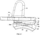
Figure 2 is a side (medial or lateral) view of the first and second prosthetic ankle components during assembly according to an example of the present invention; -
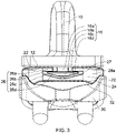
Figure 3 is an end on (posterior) view of a prosthetic ankle assembly according to an example of the present invention; -
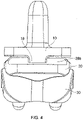
Figure 4 is an end on (anterior) view of the prosthetic ankle assembly according to an example of the present invention; -
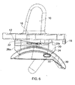
Figure 5 is a side (medial or lateral) view of the prosthetic ankle assembly during assembly according to an example of the present invention; -
Figure 6 is a side (medial or lateral) view of the prosthetic ankle assembly after assembly according to an example of the present invention; -
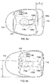
Figures 7a, 7b and 7c are side (medial or lateral), end on (posterior) and plan views respectively of a first prosthetic ankle component according to a further example of the present invention (NB, the lip has been removed fromFigure 7b for the sake of clarity); and -
Figures 8a and 8b are plan views of the first and second prosthetic ankle components according to the further example of the present invention withFigures 8a and 8b depicting translation and rotation of the second component with respect to the first component respectively. - With reference to
Figures 1 to 4 , a prosthetic ankle assembly comprises a firstprosthetic ankle component 10 and a secondprosthetic ankle component 20, which may be implanted into the ankle joint of a patient. The prosthetic ankle assembly may further comprise a third prosthetic ankle component 30 (depicted inFigures 3 to 6 ). The firstprosthetic ankle component 10 may be implanted into the tibia of the patient and may thus form a tibial component. The thirdprosthetic ankle component 30 may be implanted into the talus of the patient and may thus form a talar component. The secondprosthetic ankle component 20 may be provided between the first andfurther ankle components - The first
prosthetic ankle component 10 comprises a first bearing or articulatingsurface 12 and the secondprosthetic ankle component 20 comprises a second bearing or articulatingsurface 22. Thefirst bearing surface 12 is configured to engage thesecond bearing surface 22 such that the firstprosthetic ankle component 10 may articulate with respect to the secondprosthetic ankle component 20, for example when the prosthetic ankle assembly is implanted within the patient and during use of the ankle joint. In a similar fashion the secondprosthetic ankle component 20 comprises a further bearing or articulatingsurface 24, which is configured to engage a corresponding third bearing or articulatingsurface 32 provided on the thirdprosthetic ankle component 30. - The first
prosthetic ankle component 10 comprises aprotrusion 16 which protrudes from thefirst bearing surface 12. Theprotrusion 16 may or may not be integral with the firstprosthetic ankle component 10, e.g. the protrusion may be selectively applied to the first prosthetic ankle component, which may otherwise be used without a protrusion depending on the requirements of the patient. - The second
prosthetic ankle component 20 comprises a receiving portion is in the form of aslot 26, formed on thesecond bearing surface 22, e.g. in a substantially anterior-posterior direction. Theprotrusion 16 and/orslot 26 may be provided on the centreline of the prosthetic ankle assembly. In an alternative arrangement (not shown), two or more protrusions may be provided at opposite edges of the first bearing surface and said protrusions may engage corresponding receiving surfaces provided on the second prosthetic ankle component. In either case, theprotrusion 16 on thefirst bearing surface 12 is configured to engage the receiving portion,e.g. slot 26, such that the protrusion may slide with respect to the receiving portion, e.g. in the slot. Likewise, the receiving portion,e.g. slot 26, is configured to receive theprotrusion 16 protruding from thefirst bearing surface 12. - The further bearing
surface 24 may be provided on a surface of the secondprosthetic ankle component 20 opposite thesecond bearing surface 22. As such, the further bearingsurface 24 may extend over theslot 26 on thesecond bearing surface 22. - As depicted in
Figure 3 , the cross-sectional shape of theprotrusion 16, in a plane perpendicular to the first bearing surface 12 (and perpendicular to the length of the slot), is larger at an end of the protrusion away from the first bearing surface. Similarly, the cross-sectional shape of theslot 26, in a plane perpendicular to thesecond bearing surface 22, is larger at an end of the slot away from thesecond bearing surface 22. As a result, theprotrusion 16 andslot 26 may therefore interlock. - By way of example, the
protrusion 16 andslot 26 may have a tapered cross-section, e.g. with one or more sloping sidewalls. Alternatively, theprotrusion 16 andslot 26 may have a T-shaped or L-shaped cross-section. In other words, theprotrusion 16 may comprise aneck portion 16a and ahead portion 16b. Thehead portion 16b may be wider than theneck portion 16a, e.g. in a substantially medial-lateral direction. Theneck portion 16a may be provided between thefirst bearing surface 12 and thehead portion 16b. Accordingly, thehead portion 16b may be provided on the top of theprotrusion 16. - In a similar fashion, the
slot 26 may comprise anarrow portion 26a and awide portion 26b. Thewide portion 26b may be wider than thenarrow portion 26a, e.g. in a substantially medial-lateral direction. Thenarrow portion 26a may be provided between thesecond bearing surface 22 and thewide portion 26b. Accordingly, thewide portion 26b may be provided at the bottom of theslot 26 and the wide portion may form afloor 26c of the slot. As shown, thefloor 26c of the slot may comprise a curved, e.g. concave, profile. Similarly, thehead portion 16b may comprise a curved, e.g. convex,top surface 16c. - The
protrusion 16 comprises afirst abutment surface 16d which is formed by a surface of thehead portion 16b that faces thefirst bearing surface 12. Likewise, theslot 26 comprises asecond abutment surface 26d which is formed by a surface at the interface between the narrow andwide portions floor 26c of theslot 26. The first andsecond abutment surfaces prosthetic ankle components prosthetic ankle components slot - The
protrusion 16 and/orslot 26 may be elongate, e.g. extending along at least a portion of therespective bearing surface neck portion 16a and/orhead portion 16b of the protrusion may be elongate, e.g. in a substantially anterior-posterior direction. In the particular example shown, theneck portion 16a andhead portion 16b may have the same length in the substantially anterior-posterior direction, although it is also envisaged that the neck portion may have a length that is greater or less than the length of the head portion. However, theprotrusion 16 may not be elongate, e.g. with theneck portion 16a and/orhead portion 16b having a circular or square cross-sectional shape, i.e. in a plane substantially parallel to the first bearing surface. For example, theprotrusion 16 may be mushroom shaped. In any event, theslot 26 is longer than theprotrusion 16 to permit sliding movement of the protrusion in the slot. In this way, theprotrusion 16 andslot 26 are configured such that their mutual interaction permits the first and secondprosthetic ankle components prosthetic ankle components slot 26. - In addition to the above described sliding action, the
protrusion 16 and/orslot 26 may be configured to permit relative rotation between the first and secondprosthetic ankle components protrusion 16 may be circular in a plane parallel to thefirst bearing surface 12, thereby permitting relative rotation between the first and secondprosthetic ankle components protrusion 16 may not form a tight fit in theslot 26, e.g. with the neck andhead portions protrusion 16 being smaller in width than the narrow andwide portions slot 26 respectively. - However, whilst a degree of rotation between the first and second
prosthetic ankle components protrusion 16 and/orslot 26 may be configured such that the amount of relative rotation between the first and second prosthetic ankle components may be limited. For example, theprotrusion 16 may not form a tight fit in theslot 26. In particular, whilst the neck andhead portions protrusion 16 may be smaller in width than the narrow andwide portions slot 26 respectively, the neck and/orhead portions protrusion 16 may be sized with respect to the narrow andwide portions slot 26 respectively such that relative rotation is limited. In this regard, corners of the neck and/orhead portions protrusion 16 may abut sidewalls of the narrow andwide portions slot 26 respectively to limit the relative rotation between the first and secondprosthetic ankle components head portions protrusion 16 jamming in theslot 26. - In an alternative arrangement (not shown) the protrusion may form a tight fit in the slot, e.g. so that relative rotation between the first and second prosthetic ankle components may not be permitted.
- To permit assembly, an
opening 27 to theslot 26 is provided in afirst end wall 28a of the secondprosthetic ankle component 20. Thefirst end wall 28a and hence opening 27 may be angled or substantially perpendicular to thesecond bearing surface 22 andslot 26. Accordingly, theopening 27 may be arranged to receive theprotrusion 16 during assembly of the first and secondprosthetic ankle components Figure 2 . Theopening 27 may be provided at a posterior end of the secondprosthetic ankle component 20. By contrast, theslot 26 may be closed at the opposite end of the slot to theopening 27, e.g. at the anterior end of the slot, thereby limiting bearing motion posteriorly. - During an ankle replacement operation, the surgeon may only have limited access to the ankle joint from the anterior side. By providing the
opening 27 in thefirst end wall 28a, the surgeon may readily slide the secondprosthetic ankle component 20 onto the firstprosthetic ankle component 10. - As shown in
Figure 1 ,2 and4 , the firstprosthetic ankle component 10 comprises alip 18. Thelip 18 is provided at or towards an edge of thefirst bearing surface 12 and thelip 18 may be provided at an anterior end of the prosthetic ankle. Thelip 18 may protrude from an edge of thefirst bearing surface 12 and may provide anabutment surface 19 against which an edge of the secondprosthetic ankle component 20 may abut. Thelip 18 is configured to limit sliding movement of the first and secondprosthetic ankle components prosthetic ankle component 20 may comprise anindent 29 which may correspond to and receive thelip 18 andabutment surface 19. - As depicted in
Figure 2 , thelip 18 may be configured such that during assembly of the first and secondprosthetic ankle components edge 25 of thesecond bearing surface 22 may ride over thelip 18. Theedge 25 may be the edge between thesecond bearing surface 22 and asecond end wall 28b of the secondprosthetic ankle component 20. Thesecond end wall 28b is opposite thefirst end wall 28a which comprises theopening 27 of the secondprosthetic ankle component 20. Thelip 18 may be further configured such that the first and secondprosthetic ankle components edge 25 of the secondprosthetic ankle component 20 riding over thelip 18 during assembly of the first and second prosthetic ankle components. For example, at least a portion of the secondprosthetic ankle component 20 may flex during assembly to allow theedge 25 to ride over thelip 18. At least a portion of the secondprosthetic ankle component 20 may be made from a resilient material, such as a polymer. In a particular example the secondprosthetic ankle component 20 may be made from an Ultra-high-molecular-weight polyethylene (UHMWPE) such as a highly cross-linked UHMWPE. In a further example, the secondprosthetic ankle component 20 may be made from Polyetheretherketone (PEEK). - It will be appreciated that the
protrusion 16,slot 26 andlip 18 may prevent the secondprosthetic ankle component 20 from becoming dislodged during use. However, the secondprosthetic ankle component 20 may subsequently be dislodged from the firstprosthetic ankle component 10, e.g. by a surgeon using a tool to prize the first and second prosthetic ankle components apart. - Although in the example shown the first and second
prosthetic ankle components slot lip 18 may be provided on either of the first or secondprosthetic ankle components prosthetic ankle component 10 may be implanted into the talus and the thirdprosthetic ankle component 30 may be implanted into the tibia. - In a further example depicted in
Figures 7 and8 , theneck portion 116a of the first prostheticankle component protrusion 116 may have a length in a substantially anterior-posterior direction that is greater than the length of thehead portion 116b of the protrusion. Theneck portion 116a may be elongate, for example, as depicted the neck portion may be obround shaped (i.e. an oblong with rounded ends). By contrast, thehead portion 116b may not be elongate, for example the head portion may be circular, e.g. in a plane parallel to the bearing surface. The further example ofFigures 7 and8 is otherwise substantially the same as the prosthetic ankle assembly described above and features of the above example may apply equally to the further example. In particular, thefirst ankle component 110 of the further example may slidably engage a secondprosthetic ankle component 120 similar to that described above. - As best viewed in
Figure 7c , theneck portion 116a may comprisecurved ends Figures 8a and 8b , thecorresponding slot 126 in the secondprosthetic ankle component 120 may also comprise acurved end 126e. Thenarrow portion 126a of theslot 126 may have acurved end 126e' with a first radius of curvature, whilst thewide portion 126b may have acurved end 126e" with a second radius of curvature, which may be greater than the first radius of curvature. As depicted, apexes of the curved ends 126e' and 126e" may coincide, or alternatively, the apexes of the curved ends 126e' and 126e" may be spaced apart. - Referring to
Figures 8a and 8b , translation and/or rotation of the secondprosthetic ankle component 120 may be permitted with respect to the firstprosthetic ankle component 110. For example, as depicted inFigure 8a , the protrusion and slot arrangement of the further example may permit translation of the secondprosthetic ankle component 120 with respect to thefirst ankle component 110 by an amount δ. Theneck portion 116a may limit the travel of the secondprosthetic ankle component 120, e.g. in the anterior-posterior direction. Theneck portion end 116e may abut theclosed end 126e of theslot 126, in particular, theend 126e' of the slotnarrow portion 126a. By contrast, the secondprosthetic ankle component 120 may abut thelip 118 of thefirst ankle component 110 to limit the travel in the opposite direction. - As depicted in
Figure 8b , the protrusion and slot arrangement may permit rotation of the secondprosthetic ankle component 120 with respect to thefirst ankle component 110. Theneck portion 116a may be narrower than the correspondingnarrow portion 126a of the slot 126 (e.g. in a substantially medial-lateral direction), thereby permitting rotation of the secondprosthetic ankle component 120 with respect to the firstprosthetic ankle component 110. Theprotrusion neck portion 116a and/or slotnarrow portion 126a width and/or the protrusion neck portion length may be sized so as to limit the degree of rotation by a predetermined amount. The neck portion may limit rotation of the secondprosthetic ankle component 120 from an aligned position with respect to the firstprosthetic ankle component 110 by an angle of α degrees, for example, the neck portion may limit the rotation by 2 degrees. In other words, the second ankle component may rotate by a total of 2α degrees, e.g. 4 degrees, from one extreme to another. - As depicted, side walls of the
neck portion 116a andnarrow portion 126a may be substantially parallel, however, in an alternative arrangement the sidewalls of the neck portion and/or narrow portion may be tapered. In this way the amount of permitted rotation between the first and second prosthetic ankle components may be varied at particular translational positions. - It will be appreciated that the translation and/or rotation of the further example depicted in
Figures 7 and8 may better match the anatomical range of motion.
Claims (12)
- A prosthetic ankle assembly comprising a first prosthetic ankle component (10) and a second prosthetic ankle component (20), the first prosthetic ankle component comprising:a first bearing surface (12) configured to slidably engage a second bearing surface (22) of the second prosthetic ankle component (20) when the first and second prosthetic ankle components are in an installed configuration; andone or more protrusions (16) protruding from the first bearing surface, the protrusions being configured to be received by one or more corresponding receiving portions provided on the second prosthetic ankle component,wherein the one or more protrusions are further configured such that the interaction with the receiving portions permits the first and second prosthetic ankle components to slide with respect to one another in an interface plane defined by the interface between the first and second bearing surfaces, and wherein the protrusions are further configured to restrict the first and second prosthetic ankle components moving away from one another in a direction with a component perpendicular to the interface plane;wherein the one or more receiving portions are in the form of a slot (26) provided in the second bearing surface (22) of the second prosthetic ankle component (20);wherein an opening (27) to the slot (26) is provided in an end wall (28a) of the second prosthetic ankle component (20), the opening being arranged to receive a corresponding protrusion (16) during assembly of the first and second prosthetic ankle components;wherein the first prosthetic ankle component (10) further comprises a lip (18), the lip being provided at or towards an edge of the first bearing surface (12), the lip being configured to limit sliding movement of the first and second prosthetic ankle components.
- The prosthetic ankle assembly of claim 1, wherein the lip (18) is configured such that during assembly of the first and second prosthetic ankle components (10,20) an edge (25) of the first or second bearing surface opposite the lip may ride over the lip.
- The prosthetic ankle assembly of claim 1 or claim 2, wherein the lip (18) is further configured such that the first and second prosthetic ankle components (10,20) resiliently lock together by virtue of the edge (25) of the opposing bearing surface riding over the lip during assembly of the first and second prosthetic ankle components.
- The prosthetic ankle assembly of any of claims 1 to 3, wherein the one or more protrusions (16) and/or receiving portions cross-sectional shape is larger at an end of the protrusion or receiving portion away from the respective bearing surface.
- The prosthetic ankle assembly of claim 4, wherein the one or more protrusions (16) and/or receiving portion has a T-shaped or L-shaped cross-section.
- The prosthetic ankle assembly of claim 4 or 5, wherein the one or more protrusions (16) comprise a neck portion (16a) and a head portion (16b), the neck portion having a length that is greater than the length of the head portion.
- The prosthetic ankle assembly of any of claims 1 to 6, wherein the protrusions (16) and/or receiving portions are configured to permit relative rotation between the first and second prosthetic ankle components (10,20).
- The prosthetic ankle assembly of claim 7, wherein the protrusions (16) and/or receiving portions are configured such that the amount of relative rotation between the first and second prosthetic ankle components (10,20) is limited.
- The prosthetic ankle assembly of any of claims 1 to 8, further comprising a third prosthetic ankle component (30), wherein one of the first or second prosthetic ankle component (10,20) comprises a further bearing surface (24) configured to engage the third prosthetic ankle component (30).
- The prosthetic ankle assembly of claim 9, wherein the one of the first or second prosthetic ankle component (10,20) is a bearing insert provided between the other of the first and second prosthetic ankle components and the third prosthetic ankle component (30).
- The prosthetic ankle assembly of claim 9 or 10, wherein the further bearing surface (24) is provided on a surface of the first or second prosthetic ankle component opposite the respective first or second bearing surface (12,22), the further bearing surface extending over the respective protrusions (16) or receiving portions on the opposite bearing surface.
- The prosthetic ankle assembly of any of claims 9 to 11, wherein the other of the first or second prosthetic ankle component (10,20) is configured to be connected to the tibia of a patient and the third prosthetic ankle component (30) is configured to be connected to the talus of the patient.
Applications Claiming Priority (2)
| Application Number | Priority Date | Filing Date | Title |
|---|---|---|---|
| GB1206127.1A GB2500918A (en) | 2012-04-05 | 2012-04-05 | A prosthetic ankle with sliding engaging components |
| PCT/GB2013/050885 WO2013150308A1 (en) | 2012-04-05 | 2013-04-04 | Prosthetic ankle components |
Publications (2)
| Publication Number | Publication Date |
|---|---|
| EP2833841A1 EP2833841A1 (en) | 2015-02-11 |
| EP2833841B1 true EP2833841B1 (en) | 2023-01-04 |
Family
ID=46160395
Family Applications (1)
| Application Number | Title | Priority Date | Filing Date |
|---|---|---|---|
| EP13719138.3A Active EP2833841B1 (en) | 2012-04-05 | 2013-04-04 | Prosthetic ankle components |
Country Status (9)
| Country | Link |
|---|---|
| US (2) | US9655734B2 (en) |
| EP (1) | EP2833841B1 (en) |
| JP (1) | JP6072220B2 (en) |
| CN (1) | CN104411272B (en) |
| AU (1) | AU2013245411B2 (en) |
| CA (1) | CA2869107C (en) |
| GB (1) | GB2500918A (en) |
| WO (1) | WO2013150308A1 (en) |
| ZA (1) | ZA201406707B (en) |
Families Citing this family (14)
| Publication number | Priority date | Publication date | Assignee | Title |
|---|---|---|---|---|
| GB2500918A (en) | 2012-04-05 | 2013-10-09 | Biomet Uk Healthcare Ltd | A prosthetic ankle with sliding engaging components |
| EP2991589B1 (en) * | 2013-05-01 | 2022-09-14 | Ndsu Research Foundation | Improved ankle replacement apparatus and method |
| CN103598936B (en) * | 2013-10-21 | 2016-02-24 | 上海市第十人民医院 | A kind of combination type tumorous type ankle prosthesis |
| US9579210B2 (en) * | 2014-11-07 | 2017-02-28 | Wright Medical Technology, Inc. | Talar dome fixation stem |
| US10456265B2 (en) * | 2015-01-07 | 2019-10-29 | Wright Medical Technology, Inc. | Fixation mechanism for an implant |
| AU2016388305B2 (en) * | 2015-01-20 | 2019-06-06 | Advita Ortho, LLC. | Talar implant for modifying joint kinematics |
| US9877839B2 (en) | 2015-08-25 | 2018-01-30 | Wright Medical Technology, Inc. | Modular talar fixation method and system |
| US20170056188A1 (en) * | 2015-08-25 | 2017-03-02 | Wright Medical Technology, Inc. | Total ankle talar prosthesis with anchor holes and grooves |
| CN105030385A (en) * | 2015-08-27 | 2015-11-11 | 江苏奥康尼医疗科技发展有限公司 | All-organic high molecular material ankle joint prosthesis |
| US20170340450A1 (en) * | 2016-05-25 | 2017-11-30 | Arbelaez Jose Bernardo Toro | Reverse Ankle Replacement System |
| US10136998B2 (en) * | 2016-08-30 | 2018-11-27 | Wright Medical Technology, Inc. | Revision total ankle implants |
| CN106618807A (en) * | 2016-11-17 | 2017-05-10 | 中国人民解放军第三军医大学第附属医院 | Detachable talus prosthesis |
| FR3070593A1 (en) * | 2017-09-05 | 2019-03-08 | In2Bones | PROSTHESIS OF IMPROVED ANKLE |
| TWI786139B (en) * | 2018-06-22 | 2022-12-11 | 財團法人工業技術研究院 | Artificial joint |
Citations (1)
| Publication number | Priority date | Publication date | Assignee | Title |
|---|---|---|---|---|
| WO2011101699A1 (en) * | 2010-02-19 | 2011-08-25 | Newdeal | An ankle prosthesis with simplified adjustment |
Family Cites Families (21)
| Publication number | Priority date | Publication date | Assignee | Title |
|---|---|---|---|---|
| PT791344E (en) * | 1996-02-21 | 2002-01-30 | Plus Endoprothetik Ag | KNEE JOINT ENDOPROTSIS |
| WO1999018895A1 (en) * | 1997-09-08 | 1999-04-22 | Prosthetic Design, Inc. | Prosthetic foot with lateral and angular adjustability |
| US6660039B1 (en) | 1998-05-20 | 2003-12-09 | Smith & Nephew, Inc. | Mobile bearing knee prosthesis |
| US6863691B2 (en) * | 2002-04-29 | 2005-03-08 | Timothy J. Short | Ankle implant |
| US8388684B2 (en) * | 2002-05-23 | 2013-03-05 | Pioneer Signal Technology, Inc. | Artificial disc device |
| GB2404862A (en) | 2003-08-15 | 2005-02-16 | Biomet Merck Ltd | Prosthesis with adjustable bearing retainer |
| JP4191194B2 (en) * | 2003-08-27 | 2008-12-03 | ヴァルデマール・リンク・ゲゼルシャフト・ミット・ベシュレンクテル・ハフツング・ウント・コムパニー・コマンディットゲゼルシャフト | Ankle endoprosthesis |
| US7462201B2 (en) | 2003-10-21 | 2008-12-09 | Freedom Innovations, Llc | Prosthetic foot with an adjustable ankle and method |
| US6966933B2 (en) * | 2003-10-21 | 2005-11-22 | Roland J. Christensen, As Operating Manager Of Rjc Development, Lc, General Partner Of The Roland J. Christensen Family Limited Partnership | Prosthetic foot with an adjustable ankle and method |
| US7520904B2 (en) | 2003-10-21 | 2009-04-21 | Freedom Innovations, Llc | Prosthetic foot with an adjustable ankle and method |
| CA2601090C (en) * | 2005-03-14 | 2013-08-20 | Inbone Technologies, Inc. | Ankle replacement system |
| AU2006326312A1 (en) | 2005-12-12 | 2007-06-21 | Link America, Inc. | Endoprosthesis with intermediate part |
| CN101534751A (en) * | 2006-09-15 | 2009-09-16 | 先锋外科技术公司 | Joint arthroplasty devices having articulating members |
| EP2063817A4 (en) * | 2006-09-15 | 2012-04-18 | Pioneer Surgical Technology Inc | ARTICULAR ARTHROPLASTY DEVICES HAVING JOINT ELEMENTS |
| US9278006B2 (en) * | 2006-10-26 | 2016-03-08 | European Foot Platform Sc | Ankle prosthesis with neutral position adjustment |
| US20110035019A1 (en) * | 2009-07-09 | 2011-02-10 | Wright State University | Total ankle replacement system |
| CN102048600B (en) * | 2009-10-27 | 2013-06-12 | 上海交通大学医学院附属第九人民医院 | Total ankle plus total talus prosthesis |
| GB2479899A (en) | 2010-04-28 | 2011-11-02 | Biomet Uk Ltd | Alignment tool for use in joint replacement |
| US8591596B2 (en) * | 2010-05-28 | 2013-11-26 | DePuy Synthes Products, LLC | Semi-constrained ankle prosthesis having a rotating bearing insert |
| US20120010718A1 (en) * | 2010-07-08 | 2012-01-12 | Still Gregory P | Partial ankle joint replacement implant |
| GB2500918A (en) | 2012-04-05 | 2013-10-09 | Biomet Uk Healthcare Ltd | A prosthetic ankle with sliding engaging components |
-
2012
- 2012-04-05 GB GB1206127.1A patent/GB2500918A/en not_active Withdrawn
-
2013
- 2013-04-04 CN CN201380018651.7A patent/CN104411272B/en active Active
- 2013-04-04 CA CA2869107A patent/CA2869107C/en active Active
- 2013-04-04 JP JP2015503942A patent/JP6072220B2/en active Active
- 2013-04-04 AU AU2013245411A patent/AU2013245411B2/en active Active
- 2013-04-04 WO PCT/GB2013/050885 patent/WO2013150308A1/en not_active Ceased
- 2013-04-04 EP EP13719138.3A patent/EP2833841B1/en active Active
- 2013-04-04 US US14/390,202 patent/US9655734B2/en active Active
-
2014
- 2014-09-12 ZA ZA2014/06707A patent/ZA201406707B/en unknown
-
2017
- 2017-04-12 US US15/485,647 patent/US10188523B2/en active Active
Patent Citations (2)
| Publication number | Priority date | Publication date | Assignee | Title |
|---|---|---|---|---|
| WO2011101699A1 (en) * | 2010-02-19 | 2011-08-25 | Newdeal | An ankle prosthesis with simplified adjustment |
| EP2536362A1 (en) * | 2010-02-19 | 2012-12-26 | Newdeal | An ankle prosthesis with simplified adjustment |
Also Published As
| Publication number | Publication date |
|---|---|
| CN104411272A (en) | 2015-03-11 |
| CA2869107C (en) | 2019-06-04 |
| US10188523B2 (en) | 2019-01-29 |
| ZA201406707B (en) | 2017-08-30 |
| AU2013245411B2 (en) | 2017-06-08 |
| US9655734B2 (en) | 2017-05-23 |
| US20170216041A1 (en) | 2017-08-03 |
| AU2013245411A1 (en) | 2014-09-25 |
| CA2869107A1 (en) | 2013-10-10 |
| CN104411272B (en) | 2017-07-18 |
| GB201206127D0 (en) | 2012-05-16 |
| WO2013150308A1 (en) | 2013-10-10 |
| US20150057761A1 (en) | 2015-02-26 |
| GB2500918A (en) | 2013-10-09 |
| EP2833841A1 (en) | 2015-02-11 |
| JP6072220B2 (en) | 2017-02-01 |
| JP2015512316A (en) | 2015-04-27 |
Similar Documents
| Publication | Publication Date | Title |
|---|---|---|
| CA2869107C (en) | Prosthetic ankle components | |
| US11369478B2 (en) | Orthopaedic knee prosthesis having controlled condylar curvature | |
| US11337823B2 (en) | Orthopaedic femoral component having controlled condylar curvature | |
| CA2859911C (en) | Cruciate-retaining tibial prosthesis | |
| US20200113702A1 (en) | Tibial prosthesis | |
| US8192498B2 (en) | Posterior cructiate-retaining orthopaedic knee prosthesis having controlled condylar curvature | |
| US7875077B2 (en) | Support structure device and method | |
| EP2726020B1 (en) | Posterior stabilized orthopaedic knee prosthesis having controlled condylar curvature | |
| NZ544723A (en) | Intervertebral implant comprising temporary blocking means | |
| US20090326658A1 (en) | Intervertebral prosthetic disc and method of installing same | |
| US20140128973A1 (en) | Knee prosthesis | |
| AU2005206119B2 (en) | Support structure device and method | |
| EP2962667A1 (en) | Cruciate-retaining tibial prosthesis |
Legal Events
| Date | Code | Title | Description |
|---|---|---|---|
| PUAI | Public reference made under article 153(3) epc to a published international application that has entered the european phase |
Free format text: ORIGINAL CODE: 0009012 |
|
| 17P | Request for examination filed |
Effective date: 20141103 |
|
| AK | Designated contracting states |
Kind code of ref document: A1 Designated state(s): AL AT BE BG CH CY CZ DE DK EE ES FI FR GB GR HR HU IE IS IT LI LT LU LV MC MK MT NL NO PL PT RO RS SE SI SK SM TR |
|
| AX | Request for extension of the european patent |
Extension state: BA ME |
|
| DAX | Request for extension of the european patent (deleted) | ||
| STAA | Information on the status of an ep patent application or granted ep patent |
Free format text: STATUS: EXAMINATION IS IN PROGRESS |
|
| 17Q | First examination report despatched |
Effective date: 20170320 |
|
| GRAP | Despatch of communication of intention to grant a patent |
Free format text: ORIGINAL CODE: EPIDOSNIGR1 |
|
| STAA | Information on the status of an ep patent application or granted ep patent |
Free format text: STATUS: GRANT OF PATENT IS INTENDED |
|
| INTG | Intention to grant announced |
Effective date: 20220714 |
|
| GRAS | Grant fee paid |
Free format text: ORIGINAL CODE: EPIDOSNIGR3 |
|
| GRAA | (expected) grant |
Free format text: ORIGINAL CODE: 0009210 |
|
| STAA | Information on the status of an ep patent application or granted ep patent |
Free format text: STATUS: THE PATENT HAS BEEN GRANTED |
|
| AK | Designated contracting states |
Kind code of ref document: B1 Designated state(s): AL AT BE BG CH CY CZ DE DK EE ES FI FR GB GR HR HU IE IS IT LI LT LU LV MC MK MT NL NO PL PT RO RS SE SI SK SM TR |
|
| REG | Reference to a national code |
Ref country code: GB Ref legal event code: FG4D |
|
| REG | Reference to a national code |
Ref country code: CH Ref legal event code: EP |
|
| REG | Reference to a national code |
Ref country code: AT Ref legal event code: REF Ref document number: 1541432 Country of ref document: AT Kind code of ref document: T Effective date: 20230115 |
|
| REG | Reference to a national code |
Ref country code: DE Ref legal event code: R096 Ref document number: 602013083164 Country of ref document: DE |
|
| REG | Reference to a national code |
Ref country code: IE Ref legal event code: FG4D |
|
| REG | Reference to a national code |
Ref country code: LT Ref legal event code: MG9D |
|
| REG | Reference to a national code |
Ref country code: NL Ref legal event code: MP Effective date: 20230104 |
|
| REG | Reference to a national code |
Ref country code: AT Ref legal event code: MK05 Ref document number: 1541432 Country of ref document: AT Kind code of ref document: T Effective date: 20230104 |
|
| PG25 | Lapsed in a contracting state [announced via postgrant information from national office to epo] |
Ref country code: NL Free format text: LAPSE BECAUSE OF FAILURE TO SUBMIT A TRANSLATION OF THE DESCRIPTION OR TO PAY THE FEE WITHIN THE PRESCRIBED TIME-LIMIT Effective date: 20230104 |
|
| P01 | Opt-out of the competence of the unified patent court (upc) registered |
Effective date: 20230527 |
|
| PG25 | Lapsed in a contracting state [announced via postgrant information from national office to epo] |
Ref country code: RS Free format text: LAPSE BECAUSE OF FAILURE TO SUBMIT A TRANSLATION OF THE DESCRIPTION OR TO PAY THE FEE WITHIN THE PRESCRIBED TIME-LIMIT Effective date: 20230104 Ref country code: PT Free format text: LAPSE BECAUSE OF FAILURE TO SUBMIT A TRANSLATION OF THE DESCRIPTION OR TO PAY THE FEE WITHIN THE PRESCRIBED TIME-LIMIT Effective date: 20230504 Ref country code: NO Free format text: LAPSE BECAUSE OF FAILURE TO SUBMIT A TRANSLATION OF THE DESCRIPTION OR TO PAY THE FEE WITHIN THE PRESCRIBED TIME-LIMIT Effective date: 20230404 Ref country code: LV Free format text: LAPSE BECAUSE OF FAILURE TO SUBMIT A TRANSLATION OF THE DESCRIPTION OR TO PAY THE FEE WITHIN THE PRESCRIBED TIME-LIMIT Effective date: 20230104 Ref country code: LT Free format text: LAPSE BECAUSE OF FAILURE TO SUBMIT A TRANSLATION OF THE DESCRIPTION OR TO PAY THE FEE WITHIN THE PRESCRIBED TIME-LIMIT Effective date: 20230104 Ref country code: HR Free format text: LAPSE BECAUSE OF FAILURE TO SUBMIT A TRANSLATION OF THE DESCRIPTION OR TO PAY THE FEE WITHIN THE PRESCRIBED TIME-LIMIT Effective date: 20230104 Ref country code: ES Free format text: LAPSE BECAUSE OF FAILURE TO SUBMIT A TRANSLATION OF THE DESCRIPTION OR TO PAY THE FEE WITHIN THE PRESCRIBED TIME-LIMIT Effective date: 20230104 Ref country code: AT Free format text: LAPSE BECAUSE OF FAILURE TO SUBMIT A TRANSLATION OF THE DESCRIPTION OR TO PAY THE FEE WITHIN THE PRESCRIBED TIME-LIMIT Effective date: 20230104 |
|
| PG25 | Lapsed in a contracting state [announced via postgrant information from national office to epo] |
Ref country code: SE Free format text: LAPSE BECAUSE OF FAILURE TO SUBMIT A TRANSLATION OF THE DESCRIPTION OR TO PAY THE FEE WITHIN THE PRESCRIBED TIME-LIMIT Effective date: 20230104 Ref country code: PL Free format text: LAPSE BECAUSE OF FAILURE TO SUBMIT A TRANSLATION OF THE DESCRIPTION OR TO PAY THE FEE WITHIN THE PRESCRIBED TIME-LIMIT Effective date: 20230104 Ref country code: IS Free format text: LAPSE BECAUSE OF FAILURE TO SUBMIT A TRANSLATION OF THE DESCRIPTION OR TO PAY THE FEE WITHIN THE PRESCRIBED TIME-LIMIT Effective date: 20230504 Ref country code: GR Free format text: LAPSE BECAUSE OF FAILURE TO SUBMIT A TRANSLATION OF THE DESCRIPTION OR TO PAY THE FEE WITHIN THE PRESCRIBED TIME-LIMIT Effective date: 20230405 Ref country code: FI Free format text: LAPSE BECAUSE OF FAILURE TO SUBMIT A TRANSLATION OF THE DESCRIPTION OR TO PAY THE FEE WITHIN THE PRESCRIBED TIME-LIMIT Effective date: 20230104 |
|
| REG | Reference to a national code |
Ref country code: DE Ref legal event code: R097 Ref document number: 602013083164 Country of ref document: DE |
|
| PG25 | Lapsed in a contracting state [announced via postgrant information from national office to epo] |
Ref country code: SM Free format text: LAPSE BECAUSE OF FAILURE TO SUBMIT A TRANSLATION OF THE DESCRIPTION OR TO PAY THE FEE WITHIN THE PRESCRIBED TIME-LIMIT Effective date: 20230104 Ref country code: RO Free format text: LAPSE BECAUSE OF FAILURE TO SUBMIT A TRANSLATION OF THE DESCRIPTION OR TO PAY THE FEE WITHIN THE PRESCRIBED TIME-LIMIT Effective date: 20230104 Ref country code: EE Free format text: LAPSE BECAUSE OF FAILURE TO SUBMIT A TRANSLATION OF THE DESCRIPTION OR TO PAY THE FEE WITHIN THE PRESCRIBED TIME-LIMIT Effective date: 20230104 Ref country code: DK Free format text: LAPSE BECAUSE OF FAILURE TO SUBMIT A TRANSLATION OF THE DESCRIPTION OR TO PAY THE FEE WITHIN THE PRESCRIBED TIME-LIMIT Effective date: 20230104 Ref country code: CZ Free format text: LAPSE BECAUSE OF FAILURE TO SUBMIT A TRANSLATION OF THE DESCRIPTION OR TO PAY THE FEE WITHIN THE PRESCRIBED TIME-LIMIT Effective date: 20230104 |
|
| PLBE | No opposition filed within time limit |
Free format text: ORIGINAL CODE: 0009261 |
|
| STAA | Information on the status of an ep patent application or granted ep patent |
Free format text: STATUS: NO OPPOSITION FILED WITHIN TIME LIMIT |
|
| PG25 | Lapsed in a contracting state [announced via postgrant information from national office to epo] |
Ref country code: SK Free format text: LAPSE BECAUSE OF FAILURE TO SUBMIT A TRANSLATION OF THE DESCRIPTION OR TO PAY THE FEE WITHIN THE PRESCRIBED TIME-LIMIT Effective date: 20230104 |
|
| 26N | No opposition filed |
Effective date: 20231005 |
|
| PG25 | Lapsed in a contracting state [announced via postgrant information from national office to epo] |
Ref country code: LU Free format text: LAPSE BECAUSE OF NON-PAYMENT OF DUE FEES Effective date: 20230404 |
|
| REG | Reference to a national code |
Ref country code: BE Ref legal event code: MM Effective date: 20230430 |
|
| PG25 | Lapsed in a contracting state [announced via postgrant information from national office to epo] |
Ref country code: MC Free format text: LAPSE BECAUSE OF FAILURE TO SUBMIT A TRANSLATION OF THE DESCRIPTION OR TO PAY THE FEE WITHIN THE PRESCRIBED TIME-LIMIT Effective date: 20230104 |
|
| PG25 | Lapsed in a contracting state [announced via postgrant information from national office to epo] |
Ref country code: SI Free format text: LAPSE BECAUSE OF FAILURE TO SUBMIT A TRANSLATION OF THE DESCRIPTION OR TO PAY THE FEE WITHIN THE PRESCRIBED TIME-LIMIT Effective date: 20230104 Ref country code: MC Free format text: LAPSE BECAUSE OF FAILURE TO SUBMIT A TRANSLATION OF THE DESCRIPTION OR TO PAY THE FEE WITHIN THE PRESCRIBED TIME-LIMIT Effective date: 20230104 |
|
| REG | Reference to a national code |
Ref country code: IE Ref legal event code: MM4A |
|
| PG25 | Lapsed in a contracting state [announced via postgrant information from national office to epo] |
Ref country code: BE Free format text: LAPSE BECAUSE OF NON-PAYMENT OF DUE FEES Effective date: 20230430 |
|
| PG25 | Lapsed in a contracting state [announced via postgrant information from national office to epo] |
Ref country code: IE Free format text: LAPSE BECAUSE OF NON-PAYMENT OF DUE FEES Effective date: 20230404 |
|
| PG25 | Lapsed in a contracting state [announced via postgrant information from national office to epo] |
Ref country code: IE Free format text: LAPSE BECAUSE OF NON-PAYMENT OF DUE FEES Effective date: 20230404 |
|
| PG25 | Lapsed in a contracting state [announced via postgrant information from national office to epo] |
Ref country code: IT Free format text: LAPSE BECAUSE OF FAILURE TO SUBMIT A TRANSLATION OF THE DESCRIPTION OR TO PAY THE FEE WITHIN THE PRESCRIBED TIME-LIMIT Effective date: 20230104 |
|
| PG25 | Lapsed in a contracting state [announced via postgrant information from national office to epo] |
Ref country code: BG Free format text: LAPSE BECAUSE OF FAILURE TO SUBMIT A TRANSLATION OF THE DESCRIPTION OR TO PAY THE FEE WITHIN THE PRESCRIBED TIME-LIMIT Effective date: 20230104 |
|
| PG25 | Lapsed in a contracting state [announced via postgrant information from national office to epo] |
Ref country code: BG Free format text: LAPSE BECAUSE OF FAILURE TO SUBMIT A TRANSLATION OF THE DESCRIPTION OR TO PAY THE FEE WITHIN THE PRESCRIBED TIME-LIMIT Effective date: 20230104 |
|
| PGFP | Annual fee paid to national office [announced via postgrant information from national office to epo] |
Ref country code: DE Payment date: 20250313 Year of fee payment: 13 |
|
| PGFP | Annual fee paid to national office [announced via postgrant information from national office to epo] |
Ref country code: CH Payment date: 20250501 Year of fee payment: 13 |
|
| PG25 | Lapsed in a contracting state [announced via postgrant information from national office to epo] |
Ref country code: CY Free format text: LAPSE BECAUSE OF FAILURE TO SUBMIT A TRANSLATION OF THE DESCRIPTION OR TO PAY THE FEE WITHIN THE PRESCRIBED TIME-LIMIT; INVALID AB INITIO Effective date: 20130404 |
|
| PG25 | Lapsed in a contracting state [announced via postgrant information from national office to epo] |
Ref country code: HU Free format text: LAPSE BECAUSE OF FAILURE TO SUBMIT A TRANSLATION OF THE DESCRIPTION OR TO PAY THE FEE WITHIN THE PRESCRIBED TIME-LIMIT; INVALID AB INITIO Effective date: 20130404 |
|
| PG25 | Lapsed in a contracting state [announced via postgrant information from national office to epo] |
Ref country code: TR Free format text: LAPSE BECAUSE OF FAILURE TO SUBMIT A TRANSLATION OF THE DESCRIPTION OR TO PAY THE FEE WITHIN THE PRESCRIBED TIME-LIMIT Effective date: 20230104 |
|
| PGFP | Annual fee paid to national office [announced via postgrant information from national office to epo] |
Ref country code: GB Payment date: 20260326 Year of fee payment: 14 |
|
| PGFP | Annual fee paid to national office [announced via postgrant information from national office to epo] |
Ref country code: FR Payment date: 20260326 Year of fee payment: 14 |
|
| REG | Reference to a national code |
Ref country code: CH Ref legal event code: U11 Free format text: ST27 STATUS EVENT CODE: U-0-0-U10-U11 (AS PROVIDED BY THE NATIONAL OFFICE) Effective date: 20260501 |