EP2833820B1 - Surgical instrument with discrete cammed articulation - Google Patents
Surgical instrument with discrete cammed articulation Download PDFInfo
- Publication number
- EP2833820B1 EP2833820B1 EP13772043.9A EP13772043A EP2833820B1 EP 2833820 B1 EP2833820 B1 EP 2833820B1 EP 13772043 A EP13772043 A EP 13772043A EP 2833820 B1 EP2833820 B1 EP 2833820B1
- Authority
- EP
- European Patent Office
- Prior art keywords
- articulation
- end effector
- gear
- button
- spindle
- Prior art date
- Legal status (The legal status is an assumption and is not a legal conclusion. Google has not performed a legal analysis and makes no representation as to the accuracy of the status listed.)
- Active
Links
Images










Classifications
-
- A—HUMAN NECESSITIES
- A61—MEDICAL OR VETERINARY SCIENCE; HYGIENE
- A61B—DIAGNOSIS; SURGERY; IDENTIFICATION
- A61B17/00—Surgical instruments, devices or methods
-
- A—HUMAN NECESSITIES
- A61—MEDICAL OR VETERINARY SCIENCE; HYGIENE
- A61B—DIAGNOSIS; SURGERY; IDENTIFICATION
- A61B17/00—Surgical instruments, devices or methods
- A61B17/28—Surgical forceps
- A61B17/29—Forceps for use in minimally invasive surgery
- A61B17/2909—Handles
-
- A—HUMAN NECESSITIES
- A61—MEDICAL OR VETERINARY SCIENCE; HYGIENE
- A61B—DIAGNOSIS; SURGERY; IDENTIFICATION
- A61B17/00—Surgical instruments, devices or methods
- A61B17/068—Surgical staplers, e.g. containing multiple staples or clamps
- A61B17/072—Surgical staplers, e.g. containing multiple staples or clamps for applying a row of staples in a single action, e.g. the staples being applied simultaneously
-
- A—HUMAN NECESSITIES
- A61—MEDICAL OR VETERINARY SCIENCE; HYGIENE
- A61B—DIAGNOSIS; SURGERY; IDENTIFICATION
- A61B17/00—Surgical instruments, devices or methods
- A61B17/068—Surgical staplers, e.g. containing multiple staples or clamps
- A61B17/072—Surgical staplers, e.g. containing multiple staples or clamps for applying a row of staples in a single action, e.g. the staples being applied simultaneously
- A61B17/07207—Surgical staplers, e.g. containing multiple staples or clamps for applying a row of staples in a single action, e.g. the staples being applied simultaneously the staples being applied sequentially
-
- A—HUMAN NECESSITIES
- A61—MEDICAL OR VETERINARY SCIENCE; HYGIENE
- A61B—DIAGNOSIS; SURGERY; IDENTIFICATION
- A61B17/00—Surgical instruments, devices or methods
- A61B17/00234—Surgical instruments, devices or methods for minimally invasive surgery
- A61B2017/00292—Surgical instruments, devices or methods for minimally invasive surgery mounted on or guided by flexible, e.g. catheter-like, means
- A61B2017/003—Steerable
- A61B2017/00318—Steering mechanisms
- A61B2017/00323—Cables or rods
- A61B2017/00327—Cables or rods with actuating members moving in opposite directions
-
- A—HUMAN NECESSITIES
- A61—MEDICAL OR VETERINARY SCIENCE; HYGIENE
- A61B—DIAGNOSIS; SURGERY; IDENTIFICATION
- A61B17/00—Surgical instruments, devices or methods
- A61B2017/00367—Details of actuation of instruments, e.g. relations between pushing buttons, or the like, and activation of the tool, working tip, or the like
- A61B2017/00407—Ratchet means
-
- A—HUMAN NECESSITIES
- A61—MEDICAL OR VETERINARY SCIENCE; HYGIENE
- A61B—DIAGNOSIS; SURGERY; IDENTIFICATION
- A61B17/00—Surgical instruments, devices or methods
- A61B2017/0046—Surgical instruments, devices or methods with a releasable handle; with handle and operating part separable
- A61B2017/00473—Distal part, e.g. tip or head
-
- A—HUMAN NECESSITIES
- A61—MEDICAL OR VETERINARY SCIENCE; HYGIENE
- A61B—DIAGNOSIS; SURGERY; IDENTIFICATION
- A61B17/00—Surgical instruments, devices or methods
- A61B17/068—Surgical staplers, e.g. containing multiple staples or clamps
- A61B17/072—Surgical staplers, e.g. containing multiple staples or clamps for applying a row of staples in a single action, e.g. the staples being applied simultaneously
- A61B2017/07214—Stapler heads
- A61B2017/07271—Stapler heads characterised by its cartridge
-
- A—HUMAN NECESSITIES
- A61—MEDICAL OR VETERINARY SCIENCE; HYGIENE
- A61B—DIAGNOSIS; SURGERY; IDENTIFICATION
- A61B17/00—Surgical instruments, devices or methods
- A61B17/068—Surgical staplers, e.g. containing multiple staples or clamps
- A61B17/072—Surgical staplers, e.g. containing multiple staples or clamps for applying a row of staples in a single action, e.g. the staples being applied simultaneously
- A61B2017/07214—Stapler heads
- A61B2017/07278—Stapler heads characterised by its sled or its staple holder
-
- A—HUMAN NECESSITIES
- A61—MEDICAL OR VETERINARY SCIENCE; HYGIENE
- A61B—DIAGNOSIS; SURGERY; IDENTIFICATION
- A61B17/00—Surgical instruments, devices or methods
- A61B17/28—Surgical forceps
- A61B17/29—Forceps for use in minimally invasive surgery
- A61B17/2909—Handles
- A61B2017/2912—Handles transmission of forces to actuating rod or piston
- A61B2017/2923—Toothed members, e.g. rack and pinion
-
- A—HUMAN NECESSITIES
- A61—MEDICAL OR VETERINARY SCIENCE; HYGIENE
- A61B—DIAGNOSIS; SURGERY; IDENTIFICATION
- A61B17/00—Surgical instruments, devices or methods
- A61B17/28—Surgical forceps
- A61B17/29—Forceps for use in minimally invasive surgery
- A61B2017/2926—Details of heads or jaws
- A61B2017/2927—Details of heads or jaws the angular position of the head being adjustable with respect to the shaft
Definitions
- the invention generally relates to surgical instruments, and more specifically to the articulation of surgical instruments.
- Minimally invasive surgery is performed through small incisions in the body, into which trocar ports may or may not be placed.
- One or more surgical instruments are inserted through each incision in order to perform the surgical procedure.
- Document EP 2 258 281 A2 discloses an articulation mechanism for use with a surgical apparatus having an articulating tool assembly.
- the articulation mechanism includes a rotatable shaft which is fixedly secured to a disk defining a spiral groove or slot.
- a linearly movable translation member is provided and includes a pin which is received within the spiral groove such that rotation of the disk effects linear translation of the translation member.
- US 2011/230875 A1 discloses an articulable electrosurgical instrument with an articulating capability.
- the electrosurgical instrument includes an elongated shaft having an end effector associated with a distal end thereof that is able to deliver energy to a target tissue site.
- An articulable joint is positioned between that shaft and the end effector. Articulation of the articulable joint is controlled by a stabilizable articulation actuator, which may include a rotatably stabilizable disk residing within a well.
- an exemplary end effector 4 of a surgical tool 2 may include a staple holder 8 and an anvil 6, where at least one of the staple holder 8 and the anvil 6 are rotatable and/or otherwise movable relative to one another.
- the staple holder 8 and anvil 6 need not be directly connected together in order to move relative to one another, as set forth in greater detail below.
- the staple holder 8 and the anvil 6 may be directly connected to one another in any suitable manner, if desired.
- the staple holder 8 and anvil 6 may be configured substantially as set forth in the Endocutter Document, as modified by the contents of this document.
- the staple holder 8 and anvil 6 may be fabricated from any suitable material or materials.
- both the staple holder 8 and anvil 6 may be fabricated from stainless steel.
- at least one of the staple holder 8 and anvil 6 may be fabricated at least in part from a ceramic material, to provide enhanced stiffness.
- the end effector 4 may be any other suitable item for treating or visualizing tissue, such as but not limited to at least one electrode (bipolar or otherwise), adhesive applicator, camera, ultrasound emitter, forceps, or other items.
- the end effector 4 is connected to the distal end of a shaft 10.
- the shaft 10 may be rigid along part or all of its length, and includes an articulating region 14, such as described in U.S. Patent Application Serial No. 12/400,760, filed on March 9, 2009 .
- the shaft 10 may be proximally spaced apart from the end effector 4, such that the articulating region 14 is connected to the end effector 4 and thereby spaces the shaft 10 apart from the end effector 4.
- a handle 12 is attached to the proximal end of the shaft 10, or any other suitable portion of the shaft 10.
- the shaft 10 may be fabricated integrally with the handle 12. Alternately, the shaft 10 and the handle 12 may be two separate items that are connected together in any suitable manner.
- the handle 12 includes any mechanism, mechanisms, structure or structures that are suitably configured to actuate the end effector 4.
- the handle 12 may be actuated purely by hand, meaning that the handle 12 mechanically converts force applied thereto by hand to force utilized to actuate the end effector 4.
- the handle 12 may include a source of stored energy for actuating the end effector 4.
- the source of stored energy may be mechanical (such as a spring), electrical (such as a battery), pneumatic (such as a cylinder of pressurized gas) or any other suitable source of stored energy.
- the source of stored energy, its regulation, and its use in actuating the end effector 4 may be as described in the U.S. Patent Application Serial No. 11/054,265, filed on February 9, 2005 .
- the handle 12 may instead, or also, include a connector or connectors suitable for receiving stored energy from an external source, such as a hose connected to a hospital utility source of pressurized gas or of vacuum, or an electrical cord connectable to a power source.
- one or more articulation bands 16 extend proximally from the end effector 4 through the articulation region 14 and the shaft 10 to the handle 12.
- the articulation bands 16 may be generally rectangular in cross section, where the bands 16 may be significantly greater in the height dimension than in the lateral dimension. In this way, the articulation bands 16 have a suitably low moment of inertia to allow lateral flexing of the articulation region 14. Alternately, the articulation bands 16 may have any other suitable cross-section, and such cross-section need not be constant along the length of either articulation band 16. Further, the articulation bands 16 may be composed of a material such as spring steel that allows the articulation bands 16 to provide resistance to compressive force.
- Each articulation band 16 may be fixed at or near its distal end to the end effector 4 by welding, adhesive, or any other suitable connection. Each articulation band 16 may extend to a different lateral side of the end effector 4. Alternately, at least one articulation band 16 may be oriented relative to the end effector 4.
- a central core 18 may be located proximal to the end effector 4.
- the central core 18 may be fixed to the end effector 4, such as at or near the proximal end of the end effector 4.
- the central core 18 may be compressed between the end effector 4 and the shaft 10 or a fitting in the shaft 10 proximal to the articulation region 14.
- the central core 18 may extend into and/or completely through the articulation region 14. Consequently, at least the portion of the central core 18 that is located in the articulation region 14 is flexible and/or bendable.
- at least the portion of the central core 18 located in the articulation region 14 may be composed of a flexible material, such as but not limited to silicone or elastomer.
- This flexible material may be resilient, meaning that it tends to return to a neutral state after deflection, or nonresilient, meaning that it tends to remain in a deflected state after deflection.
- at least the portion of the central core 18 located in the articulation region 14 may include a plurality of segments.
- the central core 18 may be the articulation insert described in U.S. Pat. App Serial No. 12/436,087, filed on May 5, 2009 or U.S. Pat. App. Serial No. 12/477,065, filed on June 2, 2009 (collectively referred to as the "Insert Documents").
- the central core 18 may include passages 20 defined generally longitudinally therein along which the articulation bands 16 are slidable. In this way, the passages 20 guide the articulation bands 16, particularly as articulation begins.
- At least one articulation button 22 is connected to the handle 12.
- Each articulation button 22 may be held within a knob 24.
- the knob 24 may be fixed to the shaft 10, and the shaft 10 may be rotatable relative to the handle 12 such that rotation of the knob 24 causes the shaft 10, or at least the portion of the shaft 10 rigid and proximal to the articulation region 12, to rotate about its longitudinal axis relative to the handle 12.
- the knob 24 may be fixed relative to the handle 12 such that it does not rotate or move relative to the handle 12.
- the knob 24 may be omitted altogether.
- each articulation button 22 may include a depression surface 26 that a user may press, as described in greater detail below.
- the depression surface 26 may be the most proximal surface of the articulation button 22, or may be any other suitable surface of the articulation button 22.
- a compression spring 28 may extend from the distal end of the articulation button 22, or from any other suitable portion of the articulation button 22.
- At least one pushing arm 30 may extend from the articulation button 22.
- Each pushing arm 30 may extend generally longitudinally, and flare inward near its distal end. As another example, at least one pushing arm 30 may be oriented or configured differently.
- At least one holding arm 32 may extend from the articulation button 22.
- each holding arm 32 may extend generally transversely, and flare vertically near its distal end. As another example, at least one holding arm 32 may be oriented or configured differently.
- Two articulation buttons 22 may be utilized: a left articulation button 22a and a right articulation button 22b, where "left" and "right” are defined relative to the longitudinal centerline of the shaft 10 viewed from the proximal end toward the distal end. Alternately, only a single articulation button 22 may be utilized. Where two pushing arms 30 and two holding arms 32 extend from each articulation button 22, optionally only one of each arm 30, 32 may be used by each articulation button 22 to actually control articulation. By providing two arms 30, 32 on each articulation button 22, the same articulation button 22 can be flipped.
- the gear 40 may be generally circular in shape.
- the articulation gear 40 may include outer teeth 42 defined along at least a portion of its outer perimeter 44.
- the gear 40 may include an upper surface 46 and a lower surface 48.
- At least one upper tooth 50 may extend upward from the upper surface 46.
- the upper teeth 50 may be organized into two separate arcs on the upper surface 46.
- the outer arc may include the outer, upper teeth 50a, and the inner arc may include the inner, upper teeth 50b.
- the upper teeth 50b may be omitted, and the upper teeth 50a may be organized into a single arc on the upper surface 46.
- the outer, upper teeth 50a may be organized into an arc, where a neutral tooth 50c occupies the center of the arc.
- the neutral tooth 50c may have two substantially vertical lateral walls 52.
- the upper surface 53 of the neutral tooth 50c may be substantially horizontal.
- each outer, upper tooth 50a may include a ramp surface 54 sloping upward and away from the neutral tooth 50c.
- Each upper tooth 50a may include a vertical wall 56 opposite the ramp surface 54.
- the upper surface 58 of each upper tooth 50a may be substantially horizontal.
- each upper tooth 50a may be shaped in a different manner.
- each upper tooth 50a may be substantially aligned with a radius of the gear 40.
- at least one upper tooth 50a may be oriented differently on the upper surface 46 of the gear.
- the inner, upper teeth 50b may be organized into an arc as well, where the neutral tooth 50c is positioned further from the center of the gear 40 than the inner, upper teeth 50b.
- each inner, upper tooth 50b may include a ramp surface 60 sloping upward and away from the neutral tooth 50c.
- Each inner, upper tooth 50b may include a vertical wall 62 opposite the ramp surface 60.
- each upper tooth 50a may be substantially horizontal.
- each inner, upper tooth 50b may be shaped in a different manner.
- the vertical wall 56 of each upper tooth 50a, and an arbitrary line parallel to the upper surface 46 of the gear 40 lying on the ramp surface 54 of each upper tooth 50a, may be substantially angled relative to a radius of the gear 40, and thus out of alignment with a radius of the gear 40.
- at least one upper tooth 50a may be oriented differently on the upper surface 46 of the gear 40.
- a spindle 70 may extend substantially perpendicular to the gear 40.
- the longitudinal centerline of the spindle 70 may extend through the geometric center of the gear 40. Alternately, the longitudinal centerline of the spindle 70 may be offset from the center of the gear 40.
- the spindle 70 may include an upper spindle 72 that extends upward from the upper surface 46 of the gear 40 and a lower spindle 74 that extends downward from the lower surface 48 of the gear 40. Referring also to FIG. 9 , the spindle 70 is received in at least one receiver 76 defined in the knob 24.
- the upper spindle 72 and lower spindle 74 are each received in a separate receiver 76 in the knob 24.
- the gear 40 may be passive, and may be biased to a neutral position by a torsion spring 78.
- An anchor 80 may extend downward from the lower surface 48 of the gear 40, spaced radially apart from the lower spindle 74.
- the torsion spring 78 wraps around the spindle 70 and the anchor 80, which are spaced apart from one another, such that the torsion spring 78 biases the gear 40 to a neutral position.
- Spindle teeth 82 may extend radially outward from the spindle 70. As one example, the spindle teeth 82 extend radially outward from the upper spindle 72. As another example, the spindle teeth 82 may extend radially outward from any other portion of the spindle 70.
- the spindle teeth 82 may be generally rectangular, or may have any other suitable shape. For example, the spindle teeth 82 may be spiral or cylindrical.
- the spindle teeth 82 may be oriented such that their longer dimension is substantially vertical and their shorter dimension is horizontal. However, the spindle teeth 82 may be oriented in any other suitable direction or directions. Referring also to FIG. 10 , apertures 84 may be defined through the articulation bands 16, near the proximal ends thereof.
- the apertures 84 may be sized and shaped to receive the spindle teeth 82 therein. As described in greater detail, rotation of the gear 40 about the spindle 70 causes the spindle teeth 82 to rotate and thereby cause differential motion of the articulation bands 16, urging one articulation band 16 proximally and the other articulation band 16 distally.
- the articulation gear 40 omits the upper teeth 50 described above with regard to the previous example.
- the articulation gear 40 includes at least one cam path 100 defined therein.
- At least one cam path 100 may be a depression or similar recess defined in the articulation gear 40, with a lower surface 102.
- at least one cam path 100 may be defined completely through the articulation gear 40, such that it does not have a lower surface 102.
- Each cam path 100 is a shape with a closed perimeter, and each cam path 100 has a separate, closed perimeter.
- two or more cam paths 100 may be interconnected, such as for ease of manufacturing.
- Each cam path 100 may be generally curved at least partially about the spindle 70.
- Each cam path 100 includes an inner surface 104 closer to the spindle 70 and an outer surface 106 further from the spindle 70 than the inner surface 104.
- the outer teeth 42 of this example of the articulation gear 40 may be configured substantially as set forth above with regard to the previous example of the articulation gear 40.
- each holder post 110 extend into each cam path 100.
- the holder posts 110 may be opposed ends, or other elements, of, a holder frame 112.
- each holder post 110 may reside in a first outer notch 114 in the outer surface 106 of the corresponding cam path 100.
- the holder posts 110 are biased outward against the corresponding outer surfaces 106 of the cam paths 100, in any suitable manner.
- the holder frame 112 may be compressed inward in order to place the holder posts 110 in the cam paths 100 during manufacture, such that the holder frame 112 is sprung outward to bias the holder posts 110 outward toward the outer surfaces 106 of the cam paths 100.
- the articulation buttons 22 utilized with the articulation gear 40 described immediately above with the cam path or paths 100 may be similar to the articulation buttons 22 described in the previous example, with a holder post deflection cam 120 defined on an inner surface 122 of each articulation button 22.
- the holder post deflection cam 120 may be located in proximity to and above the corresponding pushing arm 32 extending from the articulation button 22. Alternately, the holder post deflection cam 120 may be located in a different position on the articulation button 22.
- the holding arms 32 may be omitted from the articulation button 22.
- a portion of at least one feeder belt 90 may extend from the shaft 10 into, or be positioned within, the end effector 4.
- the feeder belt 90 and its associated hardware may be as set forth in U.S. Pat. App. Serial No. 11/851,379, filed September 6, 2007 ; U.S. Pat. App. Serial No. 11/956,988, filed December 14, 2007 ; and U.S. Pat. App. Serial No. 12/263,171, filed October 31, 2008 (the "Endocutter Documents").
- the feeder belt 90 will not be described in detail herein.
- Each feeder belt 90 may be a long, narrow, thin strip of material from which one or more staples 92 extend.
- At least one staple 90 may be integral with the feeder belt 90, and frangibly connected to the feeder belt 90 at one end, with the other end of the staple being free.
- One row 94 of staples 92 may be located along each side of the feeder belt 90.
- Each feeder belt 90 may be movable relative to the end effector 4, as set forth in the Endocutter Applications, such that the end effector 4 can be actuated multiple times without the need to exchange cartridges or remove the end effector 4 from the patient between actuations.
- the end effector 4 may be configured generally as set forth in the Endocutter Documents, as one example, or may be configured differently.
- the user possesses the surgical tool 2.
- the end effector 4 is placed in the body in proximity to its desired location relative to tissue.
- the end effector 4 is advanced through a trocar port or other minimally-invasive opening into the body.
- the end effector 4 may be opened such that at least the distal end of the anvil 6 is spaced apart from the staple holder 8 to allow tissue to be placed therebetween.
- the end effector 4 may be any other implement for treating tissue.
- the user actuates one of the articulation buttons 22.
- Articulation “leftward” refers to motion of the end effector 4 generally to the left as viewed by the user from the proximal toward the distal direction.
- the user actuates the right articulation button 22b.
- the "right" articulation button 22b is the one on the right as viewed by the user from the proximal toward the distal direction. Actuation of the right articulation button 22b may be performed by pressing the right articulation button 22b generally distally. This exertion of force on the right articulation button 22b overcomes the bias exerted by the compression spring 28 against the right articulation button 22b in the proximal direction.
- FIGS. 4-5 , 7-8 and 10 showing an embodiment not covered by the claimed invention
- the pushing arms 30 and holding arms 32 fixed to the right articulation button 22b advance distally as well.
- FIG. 11 as the lower pushing arm 30 advances, it encounters and engages an outer tooth 42 of the articulation gear 40. Because the outer tooth 42 is laterally spaced from the spindle 70, the force exerted by the lower pushing arm 30 on the outer tooth 42 in the distal direction creates a moment about the spindle 70, causing the articulation gear 40 to rotate. As viewed from the underside of the articulation gear 40 in FIG.
- the articulation gear 40 rotates in a clockwise direction. Consequently, as viewed from above, the articulation gear 40 rotates in a counterclockwise direction.
- the outer, upper teeth 50a of the articulation gear 40 rotate with the articulation gear 40.
- the lower holding arm 32 of the left articulation button 22a slides up the ramp surface 54 of the outer, upper tooth 50a that is immediately to the left of the neutral tooth 50c, as viewed from the top.
- the lower holding arm 32 may flex as its distal end slides up the ramp surface 54, such that it snaps downward toward and/or against the upper surface 46 of the articulation gear 40 after it slides past the ramp surface 54 and the upper surface 58 of the outer, upper tooth 50a.
- the right articulation button 22b has been depressed distally a sufficient amount, and may be released.
- the right articulation button 22b is urged proximally to its original position by the compression spring 28.
- the lower pushing arm 30 retracts out of engagement with the outer tooth 42 it had previously urged distally.
- the lower holding arm 32 of the left articulation button 22a holds the articulation gear 40 in place.
- the torsion spring 78 biases the articulation gear 40 in a direction opposite to the direction in which the articulation gear 40 had been rotated, such that the vertical wall 56 of the outer, upper tooth 50a adjacent to the tip of the lower holding arm 32 is biased against the lower holding arm 32. In this way, the lower holding arm 32 of the left articulation button 22a holds the articulation gear 40 in position.
- the upper spindle 72 rotates with the articulation gear 40, as do the spindle teeth 82.
- the spindle teeth 82 engage apertures 84 of each articulation band 16.
- Rotation of the articulation gear 40 and upper spindle 72 in the direction described above - counterclockwise as viewed from the top - thus causes the right articulation band 16 to advance distally, and the left articulation band 16 to retract proximally.
- the left articulation band 16 may be fixed to the left side of the end effector 4, and the right articulation band 16 may be fixed to the right side of the end effector 4.
- each actuation of an articulation button 22 causes the end effector 4 to articulate a discrete and known amount.
- the user may actuate the right articulation button 22b again. If so, the articulation gear 40 rotates as described above, and the end effector 4 articulates by another discrete amount, which may be the same as or different then the previous discrete amount.
- the end effector 4 may step through several discrete steps of articulation as a result of several depressions of the right articulation button 22b. Referring also to FIG. 13 , the end effector 4 may continue to be articulated further leftward until the lower holding arm 32 of the left articulation button 22a is holding the last outer, upper tooth 50a.
- an additional actuation of the right articulation button 22a simply results in no further articulation of the end effector 4, because there is not another outer, upper tooth 50a for the lower holding arm 32 to engage.
- depression of the left articulation button 22a at this point moves the lower holding arm 32 out of engagement with the outer, upper tooth 50a that it had previously engaged, and places the distal end of the lower holding arm 32 at a location inward toward the spindle 70 such that the distal end of the lower holding arm 32 is located radially inward from each of the outer, upper teeth 50a.
- the torsion spring 78 urges the articulation gear 40 back to its neutral position, and consequently the end effector 4 returns to its original, non-articulated position in which it is substantially longitudinally aligned with the shaft 10.
- the articulation gear 40 steps in reverse toward the neutral position upon depression of the left articulation button 22a.
- the distal end of the lower holding arm 32 moves inward toward the spindle 70, out of engagement with the outer, upper tooth 50a it had previously engaged and held.
- the torsion spring 78 urges the articulation gear 40 back toward its neutral position.
- the distal end of the lower holding arm 32 encounters an inner, upper tooth 50b as the articulation gear 40 moves toward that neutral position.
- the angular force exerted by the torsion spring 78 may then hold the inner, upper tooth 50b against the lower holding arm 32, such that the articulation gear 40 rotates a discrete increment less than the discrete increments that it rotated during the previous articulation of the end effector 4 leftward. Consequently, the end effector 4 articulates rightward by a discrete angle that is less than the discrete angles through which it had articulated leftward.
- the inner, upper tooth 50b simply arrests the motion of the articulation gear 40, and the lower holding arm 32 then slides proximally into engagement with the next outer, upper tooth 50a.
- the articulation gear 40 rotates a discrete increment the same as the discrete increments in which it had rotated previously, and the end effector 4 articulates rightward by a discrete angle substantially the same as the discrete angles through which it had rotated during the previous articulation of the end effector 4 leftward.
- articulation of the end effector 4 in the left direction using the right articulation button 22b has been described above.
- Articulation of the end effector 4 in the right direction, using the left articulation button 22a is performed substantially as set forth above, in a reversed, mirror-image manner.
- the shaft 10 may be rotatable relative to the handle 12, as set forth in commonly-assigned U.S. Pat. No. 7,918,376 . In this manner, the end effector 4 can be rotated as well as articulated left and right, in order to place the end effector 4 in a desired position within a patient.
- a single articulation button 22 may be provided, rather than the two articulation buttons 22a, 22b described above. If so, the neutral position of the articulation gear 40 is a rotation all the way to one side, such that the end effector 4 is fully articulated laterally in the neutral position. The end effector 4 then may be articulated in discrete increments from that neutral position, utilizing only a single articulation button 22.
- articulation gear 40 that includes at least one cam path 100 defined therein, instead of upper teeth 50 defined thereon, articulation may be performed in a similar but different manner.
- the user actuates one of the articulation buttons 22.
- Articulation "rightward” refers to motion of the end effector 4 generally to the right as viewed by the user from the proximal toward the distal direction.
- the user actuates the left articulation button 22a.
- the "left" articulation button 22a is the one on the left as viewed by the user from the proximal toward the distal direction. Actuation of the left articulation button 22a may be performed by pressing the left articulation button 22a generally distally. This exertion of force on the left articulation button 22a overcomes the bias exerted by the compression spring 28 against the left articulation button 22a in the proximal direction.
- the pushing arm 30 fixed to the left articulation button 22a advances distally as well.
- the pushing arm 30 advances, it encounters and engages an outer tooth 42 of the articulation gear 40.
- the force exerted by the pushing arm 30 on the outer tooth 42 in the distal direction creates a moment about the spindle 70, causing the articulation gear 40 to rotate.
- the articulation gear 40 rotates in a clockwise direction.
- some of the energy of motion of the left articulation button 22a is stored in the torsion spring 78, which is thereby biased toward the neutral position of the articulation gear 40 as a result of that energy storage.
- each holder post 110 moves in the corresponding cam path 100 defined in the articulation gear 40.
- the holder post 110 closest to the left articulation button 22a may be referred to as the left holder post 110a, and the corresponding cam path 100 may be referred to as the left cam path 100a.
- the holder post 110 closest to the right articulation button 22b may be referred to as the right holder post 110b, and the corresponding cam path 100 may be referred to as the right cam path 100b.
- the distal end of the holder post deflection cam 120 encounters the left holder post 110a, urging that left holder post 110a inward, as seen in FIG. 19 .
- the holder post deflection cam 120 urges the left holder post 110a out of engagement with the corresponding first outer notch 114 in which that left holder post 110 had initially resided.
- the left holder post 110a - now out of engagement with the first outer notch 114 - can move substantially freely into the portion of the cam path 100 depicted above the left holder post 110a in FIG. 19 .
- the left holder post 110a is biased toward the outer surface 106 of the left cam path 100a, and that outer surface 106 of the left cam path 100a is smooth on the portion of the left cam path 100a that the left holder post 110a encounters during clockwise rotation of the articulation gear 40 from a neutral position (which is during rightward articulation of the end effector 4).
- the right holder post 110b remains biased outward toward the outer surface 106 of the right cam path 100b. Because the right articulation button 22b has not moved and does not move distally during rightward articulation, the holder post deflection cam 120 on the right articulation button 22b does not move, such that it does not urge the right holder post 110b out of engagement with its corresponding first outer notch 114. However, as the articulation gear 40 rotates clockwise, the right holder post 110b slides against the first ramp 116 defined in the outer surface 106 of the cam path 100b that is located distal to the first outer notch 114.
- engagement between the right holder post 110b and the first outer notch 114 prevents counterclockwise rotation of the articulation gear 40, but allows clockwise rotation of the articulation gear 40 by allowing the right holder post 110b to slide along the first ramp 116.
- the first ramp 116 may be angled toward the spindle 70, such that as the right holder post 110b slides along the first ramp 116, the first ramp 116 also urges the right holder post 110b inward toward the longitudinal centerline of the knob 24.
- the right holder post 110b slides off the proximal end of the first ramp 116 and snaps into the second outer notch 118.
- the second outer notch 118 is located in the outer surface 106 of the cam path 100b, counterclockwise from the first outer notch 114.
- the length of the first ramp 116 is related to the amount of clockwise motion of the articulation gear 40, which in turn is related to the length of distal travel of the left articulation button 22a.
- the length of the first ramp 116 corresponds to the full stroke of the left articulation button 22a such that a full stroke (i.e., complete depression) of the left articulation button 22a causes the right holder post 110b to move from the first outer notch 114 to the second outer notch 118.
- the left articulation button 22a is released, moving the left holder post 110a back into engagement with a smooth section of the outer surface 106 of the cam path 100a.
- the right holder post 110b is engaged with the second outer notch 118.
- This engagement coupled with the bias of the torsion spring 78 in the counterclockwise direction, holds the articulation gear 40 in position, such that the end effector 4 has been articulated through a discrete angle and is now held at that angle.
- engagement between the spindle teeth 82 and the articulation bands 16 causes that articulation of the end effector 4.
- Articulation of the end effector 4 through successive additional rightward angular iterations may be accomplished by repeating what is set forth above.
- successive depressions of the left articulation button 22a cause the left holder post 110a to slide along a smooth portion of the outer surface 106 of the cam path 100a, and cause the right holder post 110b to slide successively along ramps 126, 128, 130 to outer notches 121, 122, 124.
- ramps and/or notches may be provided in order to provide for more or less articulation, and/or to provide for larger or smaller discrete angles of articulation of the end effector 4.
- the user may wish to return the end effector 4 in the opposite, leftward direction at that time.
- the user may wish to articulate the end effector 4 leftward before the end effector 4 reaches a point of rightmost articulation.
- the user depresses the right articulation button 22b.
- the pushing arm 30 fixed to the right articulation button 22b advances distally as well. As the pushing arm 30 advances, it encounters and engages an outer tooth 42 of the articulation gear 40.
- the force exerted by the pushing arm 30 on the outer tooth 42 in the distal direction creates a moment about the spindle 70, causing the articulation gear 40 to rotate.
- the articulation gear 40 rotates in a counterclockwise direction.
- some of the energy of motion of the left articulation button 22a is released from the torsion spring 78, which is biased toward the neutral position of the articulation gear 40 as a result of stored energy within the spring 78.
- each holder post 110 moves in the corresponding cam path 100 defined in the articulation gear 40.
- the left holder post 110a was not previously engaged with an outer notch, and slides along a smooth portion of the outer surface of the cam path 100a as the articulation gear 40 rotates counterclockwise.
- the distal end of the holder post deflection cam 120 encounters the right holder post 110b, urging that right holder post 110b inward, as seen in FIG. 24 .
- the holder post deflection cam 120 urges the right holder post 110b out of engagement with the corresponding outer notch 124 in which that right holder post 110b had previously resided.
- the articulation described herein, returning from a previous articulation in the other direction, is performed the same way regardless of which outer notch has engaged the right holder post 110b; the discussion with regard to the final outer notch 124 is for clarity.
- the right holder post 110b As the articulation gear 40 rotates counterclockwise, the right holder post 110b is held inward from the distal end of the ramp 130 located proximal to the outer notch 124. As a result, that right holder post 110b slides between the ramp 130 and the inner surface 104 of the cam path 100b.
- the holder post deflection cam 120 engages the right holder post 110b to allow counterclockwise motion of the articulation gear 40.
- the right holder post 110b moves into engagement with the outer notch 122 located clockwise from the previous outer notch 124. That engagement prevents further counterclockwise motion of the articulation gear 40, such that the articulation back toward the neutral position is stopped, and holding the articulation gear 40 in position.
- the position occupied by the end effector 4 may be the previous discrete angular position occupied by the end effector 4 prior to the return articulation described immediately above.
- the end effector 4 has been articulated through a discrete angle and is now held at that angle.
- the right articulation button 22b is released; however, the right holder post 110b is already engaged in a notch in the outer surface 106 of the cam path 100b, such that removal of any bias inward of the right holder post 110b does not cause it to move relative to the cam path 100b.
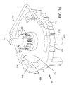
- Articulation of the end effector 4 through successive additional leftward angular iterations may be accomplished by repeating what is set forth immediately above, until the end effector 4 returns to the neutral position and the articulation gear 40 returns to the neutral position shown in FIG. 16 . After the articulation gear 40 has returned to the neutral position, end effector 4 return is complete. If the user wishes to articulate the end effector 4 further leftward, that articulation of the end effector 4 leftward may be performed as set forth above with regard to rightward articulation, but in a mirror-image manner.
- the end effector 4 may be manipulated in any manner.
- the end effector 4 may be closed if it is open, such as by moving the anvil 32 toward the staple holder 30 to clamp tissue.
- the end effector 4 then may be actuated to treat tissue.
- staples 92 may be deployed into tissue from the staple holder 6 against the anvil 4.
- the feeder belt or belts 90 then may be advanced, placing a fresh set of staples 92 in position for deployment within the staple holder 6. Such deployment and advancement may be accomplished as set forth in the Endocutter Documents.
- the end effector 4 may be reoriented in the manner described above, articulating the end effector 4 in a different direction, so the end effector 4 may treat tissue again. Alternately, the end effector 4 is simply withdrawn from the patient after the first tissue treatment.
- the operation of the surgical tool 2 may be carried out in the course of testing at a factory or other location. If so, the user that possesses the surgical tool 2 may be a technician, machine or text fixture that exercises the surgical tool 2 in the course of testing.
- tissue in the context of testing the surgical tool 2 only, includes any substance or material used as a substitute for tissue in the course of testing.
Landscapes
- Health & Medical Sciences (AREA)
- Life Sciences & Earth Sciences (AREA)
- Surgery (AREA)
- Heart & Thoracic Surgery (AREA)
- Engineering & Computer Science (AREA)
- Biomedical Technology (AREA)
- Nuclear Medicine, Radiotherapy & Molecular Imaging (AREA)
- Medical Informatics (AREA)
- Molecular Biology (AREA)
- Animal Behavior & Ethology (AREA)
- General Health & Medical Sciences (AREA)
- Public Health (AREA)
- Veterinary Medicine (AREA)
- Ophthalmology & Optometry (AREA)
- Surgical Instruments (AREA)
Description
- The invention generally relates to surgical instruments, and more specifically to the articulation of surgical instruments.
- Minimally invasive surgery is performed through small incisions in the body, into which trocar ports may or may not be placed. One or more surgical instruments are inserted through each incision in order to perform the surgical procedure. In order to effectuate one of the objectives of minimally invasive surgery, which is the minimization of incisions to the body to reduce healing time and scarring, it is desirable to minimize the number of incis made in the body. The number of incisions and their placement are determined by the particular surgical procedure to be performed and the configuration of the instruments used to carry out that procedure.
- One problem encountering during the performance of a minimally invasive surgical procedure is access to the tissue to be treated. Depending on the specific anatomy of the patient, it may be difficult to reach an area to be treated with a specific surgical instrument. As a result, one or more additional incisions may need to be made in the patient in order to access that tissue. The surgeon may need to obtain a different surgical instrument, adding to the time and expense of the procedure. Additionally, where more incisions may be made or additional instruments may be utilized, it can be difficult and/or time-consuming for the surgeon to find the surgical site again.
-
Document EP 2 258 281 A2 discloses an articulation mechanism for use with a surgical apparatus having an articulating tool assembly. The articulation mechanism includes a rotatable shaft which is fixedly secured to a disk defining a spiral groove or slot. A linearly movable translation member is provided and includes a pin which is received within the spiral groove such that rotation of the disk effects linear translation of the translation member. -
US 2011/230875 A1 discloses an articulable electrosurgical instrument with an articulating capability. The electrosurgical instrument includes an elongated shaft having an end effector associated with a distal end thereof that is able to deliver energy to a target tissue site. An articulable joint is positioned between that shaft and the end effector. Articulation of the articulable joint is controlled by a stabilizable articulation actuator, which may include a rotatably stabilizable disk residing within a well. -
-
FIG. 1 is a schematic view of a surgical tool. -
FIG. 2 is a perspective view of an exemplary surgical tool. -
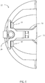
FIG. 3 is a perspective view of the end effector of the exemplary surgical tool ofFIG. 2 . -
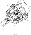
FIG. 4 is a perspective cutaway view of an articulation assembly not covered by the claimed invention, the articulation assembly being located in the handle of the exemplary surgical tool ofFIG. 2 , in a neutral configuration. -
FIG. 5 is a perspective view of an articulation button of the articulation assembly ofFIG. 4 . -
FIG. 6 is an end view of the articulation button ofFIG. 5 . -
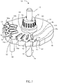
FIG. 7 is a perspective view of an articulation gear of the articulation assembly ofFIG. 4 . -
FIG. 8 is a side view of the articulation gear ofFIG. 7 . -
FIG. 9 is a perspective cutaway view of the articulation assembly ofFIG. 4 . -
FIG. 10 is a perspective cutaway view of the articulation assembly ofFIG. 4 . -
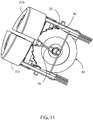
FIG. 11 is a perspective cutaway view of the articulation buttons and articulation gear during articulation through a first discrete angle. -
FIG. 12 is a perspective cutaway view of the articulation buttons and articulation gear at completion of articulation through a first discrete angle -
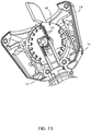
FIG. 13 is a perspective cutaway view of the articulation assembly at the limit of articulation. -
FIG. 14 is a perspective view of a feeder belt, not covered by the claimed invention, to which staples are frangibly connected. -
FIG. 15 is a top view of an articulation gear according to the invention, including at least one cam path defined therein. -
FIG. 16 is a perspective view of the articulation gear ofFIG. 15 , with a holder frame inserted into two cam paths. -
FIG. 17 is an upper cutaway view of an exemplary handle of a surgical tool according to the invention, with the articulation gear ofFIG. 15 held within the handle in a neutral position. -
FIG. 18 is a perspective view of an articulation button according to the invention. -
FIG. 19 is an upper cutaway view of a handle of the surgical tool according to the invention, with the articulation gear ofFIG. 15 held within the handle, and the left articulation button depressed. -
FIG. 20 is a perspective view of the articulation button ofFIG. 18 , engaging a holder post. -
FIG. 21 is a top view of the articulation gear and holder frame ofFIG. 16 in a second discrete position. -
FIG. 22 is a top view of the articulation gear and holder frame ofFIG. 16 in a third discrete position. -
FIG. 23 is a top view of the articulation gear and holder frame ofFIG. 16 in a fourth discrete position. -
FIG. 24 is an upper cutaway view of the handle of the surgical tool according to the invention, with the articulation gear ofFIG. 15 held within the handle, and the right articulation button depressed to begin articulation return. - The use of the same reference symbols in different figures indicates similar or identical items.
-
U.S. Patent Application Publication No. 2009/0065552, published on March 12, 2009 (the "Endocutter Document"), is referenced herewith. - Referring to
FIGS. 1-2 , anexemplary end effector 4 of asurgical tool 2 may include astaple holder 8 and ananvil 6, where at least one of thestaple holder 8 and theanvil 6 are rotatable and/or otherwise movable relative to one another. Thestaple holder 8 andanvil 6 need not be directly connected together in order to move relative to one another, as set forth in greater detail below. However, thestaple holder 8 and theanvil 6 may be directly connected to one another in any suitable manner, if desired. Thestaple holder 8 andanvil 6 may be configured substantially as set forth in the Endocutter Document, as modified by the contents of this document. Thestaple holder 8 andanvil 6 may be fabricated from any suitable material or materials. As one example, both thestaple holder 8 andanvil 6 may be fabricated from stainless steel. As another example, at least one of thestaple holder 8 andanvil 6 may be fabricated at least in part from a ceramic material, to provide enhanced stiffness. As another example, theend effector 4 may be any other suitable item for treating or visualizing tissue, such as but not limited to at least one electrode (bipolar or otherwise), adhesive applicator, camera, ultrasound emitter, forceps, or other items. Theend effector 4 is connected to the distal end of ashaft 10. Theshaft 10 may be rigid along part or all of its length, and includes anarticulating region 14, such as described inU.S. Patent Application Serial No. 12/400,760, filed on March 9, 2009 shaft 10 may be proximally spaced apart from theend effector 4, such that the articulatingregion 14 is connected to theend effector 4 and thereby spaces theshaft 10 apart from theend effector 4. - A
handle 12 is attached to the proximal end of theshaft 10, or any other suitable portion of theshaft 10. Theshaft 10 may be fabricated integrally with thehandle 12. Alternately, theshaft 10 and thehandle 12 may be two separate items that are connected together in any suitable manner. Thehandle 12 includes any mechanism, mechanisms, structure or structures that are suitably configured to actuate theend effector 4. Thehandle 12 may be actuated purely by hand, meaning that thehandle 12 mechanically converts force applied thereto by hand to force utilized to actuate theend effector 4. As another example, thehandle 12 may include a source of stored energy for actuating theend effector 4. The source of stored energy may be mechanical (such as a spring), electrical (such as a battery), pneumatic (such as a cylinder of pressurized gas) or any other suitable source of stored energy. The source of stored energy, its regulation, and its use in actuating theend effector 4 may be as described in theU.S. Patent Application Serial No. 11/054,265, filed on February 9, 2005 . Thehandle 12 may instead, or also, include a connector or connectors suitable for receiving stored energy from an external source, such as a hose connected to a hospital utility source of pressurized gas or of vacuum, or an electrical cord connectable to a power source. - Referring to
FIGS. 3-4 , one ormore articulation bands 16 extend proximally from theend effector 4 through thearticulation region 14 and theshaft 10 to thehandle 12. Thearticulation bands 16 may be generally rectangular in cross section, where thebands 16 may be significantly greater in the height dimension than in the lateral dimension. In this way, thearticulation bands 16 have a suitably low moment of inertia to allow lateral flexing of thearticulation region 14. Alternately, thearticulation bands 16 may have any other suitable cross-section, and such cross-section need not be constant along the length of eitherarticulation band 16. Further, thearticulation bands 16 may be composed of a material such as spring steel that allows thearticulation bands 16 to provide resistance to compressive force. Eacharticulation band 16 may be fixed at or near its distal end to theend effector 4 by welding, adhesive, or any other suitable connection. Eacharticulation band 16 may extend to a different lateral side of theend effector 4. Alternately, at least onearticulation band 16 may be oriented relative to theend effector 4. - A
central core 18 may be located proximal to theend effector 4. Thecentral core 18 may be fixed to theend effector 4, such as at or near the proximal end of theend effector 4. As another example, thecentral core 18 may be compressed between theend effector 4 and theshaft 10 or a fitting in theshaft 10 proximal to thearticulation region 14. Thecentral core 18 may extend into and/or completely through thearticulation region 14. Consequently, at least the portion of thecentral core 18 that is located in thearticulation region 14 is flexible and/or bendable. As one example, at least the portion of thecentral core 18 located in thearticulation region 14 may be composed of a flexible material, such as but not limited to silicone or elastomer. This flexible material may be resilient, meaning that it tends to return to a neutral state after deflection, or nonresilient, meaning that it tends to remain in a deflected state after deflection. As another example, at least the portion of thecentral core 18 located in thearticulation region 14 may include a plurality of segments. As another example, thecentral core 18 may be the articulation insert described inU.S. Pat. App Serial No. 12/436,087, filed on May 5, 2009 U.S. Pat. App. Serial No. 12/477,065, filed on June 2, 2009 central core 18 may includepassages 20 defined generally longitudinally therein along which thearticulation bands 16 are slidable. In this way, thepassages 20 guide thearticulation bands 16, particularly as articulation begins. - Referring to
FIGS. 2 and4 , at least onearticulation button 22 is connected to thehandle 12. Eacharticulation button 22 may be held within aknob 24. Optionally, theknob 24 may be fixed to theshaft 10, and theshaft 10 may be rotatable relative to thehandle 12 such that rotation of theknob 24 causes theshaft 10, or at least the portion of theshaft 10 rigid and proximal to thearticulation region 12, to rotate about its longitudinal axis relative to thehandle 12. However, theknob 24 may be fixed relative to thehandle 12 such that it does not rotate or move relative to thehandle 12. As another example, theknob 24 may be omitted altogether. - Referring also to
FIGS. 5-6 , eacharticulation button 22 may include adepression surface 26 that a user may press, as described in greater detail below. Thedepression surface 26 may be the most proximal surface of thearticulation button 22, or may be any other suitable surface of thearticulation button 22. Acompression spring 28 may extend from the distal end of thearticulation button 22, or from any other suitable portion of thearticulation button 22. At least one pushingarm 30 may extend from thearticulation button 22. Each pushingarm 30 may extend generally longitudinally, and flare inward near its distal end. As another example, at least one pushingarm 30 may be oriented or configured differently. At least one holdingarm 32 may extend from thearticulation button 22. As one example, each holdingarm 32 may extend generally transversely, and flare vertically near its distal end. As another example, at least one holdingarm 32 may be oriented or configured differently. Twoarticulation buttons 22 may be utilized: aleft articulation button 22a and aright articulation button 22b, where "left" and "right" are defined relative to the longitudinal centerline of theshaft 10 viewed from the proximal end toward the distal end. Alternately, only asingle articulation button 22 may be utilized. Where two pushingarms 30 and two holdingarms 32 extend from eacharticulation button 22, optionally only one of eacharm articulation button 22 to actually control articulation. By providing twoarms articulation button 22, thesame articulation button 22 can be flipped. - Referring to
FIGS. 4 and7-8 , anarticulation gear 40, not covered by the claimed invention, is shown. Thegear 40 may be generally circular in shape. Thearticulation gear 40 may includeouter teeth 42 defined along at least a portion of itsouter perimeter 44. Thegear 40 may include anupper surface 46 and alower surface 48. At least one upper tooth 50 may extend upward from theupper surface 46. The upper teeth 50 may be organized into two separate arcs on theupper surface 46. The outer arc may include the outer,upper teeth 50a, and the inner arc may include the inner,upper teeth 50b. As another example, theupper teeth 50b may be omitted, and theupper teeth 50a may be organized into a single arc on theupper surface 46. The outer,upper teeth 50a may be organized into an arc, where aneutral tooth 50c occupies the center of the arc. Theneutral tooth 50c may have two substantially verticallateral walls 52. Theupper surface 53 of theneutral tooth 50c may be substantially horizontal. On each side of theneutral tooth 50c, each outer,upper tooth 50a may include aramp surface 54 sloping upward and away from theneutral tooth 50c. Eachupper tooth 50a may include avertical wall 56 opposite theramp surface 54. Theupper surface 58 of eachupper tooth 50a may be substantially horizontal. As another example, eachupper tooth 50a may be shaped in a different manner. Thevertical wall 56 of eachupper tooth 50a, and an arbitrary line parallel to theupper surface 46 of thegear 40 lying on theramp surface 54 of eachupper tooth 50a, may be substantially aligned with a radius of thegear 40. Alternately, at least oneupper tooth 50a may be oriented differently on theupper surface 46 of the gear. The inner,upper teeth 50b may be organized into an arc as well, where theneutral tooth 50c is positioned further from the center of thegear 40 than the inner,upper teeth 50b. On each side of theneutral tooth 50c, each inner,upper tooth 50b may include aramp surface 60 sloping upward and away from theneutral tooth 50c. Each inner,upper tooth 50b may include avertical wall 62 opposite theramp surface 60. Theupper surface 64 of eachupper tooth 50a may be substantially horizontal. As another example, each inner,upper tooth 50b may be shaped in a different manner. Thevertical wall 56 of eachupper tooth 50a, and an arbitrary line parallel to theupper surface 46 of thegear 40 lying on theramp surface 54 of eachupper tooth 50a, may be substantially angled relative to a radius of thegear 40, and thus out of alignment with a radius of thegear 40. Alternately, at least oneupper tooth 50a may be oriented differently on theupper surface 46 of thegear 40. - A
spindle 70 may extend substantially perpendicular to thegear 40. The longitudinal centerline of thespindle 70 may extend through the geometric center of thegear 40. Alternately, the longitudinal centerline of thespindle 70 may be offset from the center of thegear 40. Thespindle 70 may include anupper spindle 72 that extends upward from theupper surface 46 of thegear 40 and alower spindle 74 that extends downward from thelower surface 48 of thegear 40. Referring also toFIG. 9 , thespindle 70 is received in at least onereceiver 76 defined in theknob 24. Advantageously, theupper spindle 72 andlower spindle 74 are each received in aseparate receiver 76 in theknob 24. Thegear 40 may be passive, and may be biased to a neutral position by atorsion spring 78. Ananchor 80 may extend downward from thelower surface 48 of thegear 40, spaced radially apart from thelower spindle 74. Thetorsion spring 78 wraps around thespindle 70 and theanchor 80, which are spaced apart from one another, such that thetorsion spring 78 biases thegear 40 to a neutral position. -
Spindle teeth 82 may extend radially outward from thespindle 70. As one example, thespindle teeth 82 extend radially outward from theupper spindle 72. As another example, thespindle teeth 82 may extend radially outward from any other portion of thespindle 70. Thespindle teeth 82 may be generally rectangular, or may have any other suitable shape. For example, thespindle teeth 82 may be spiral or cylindrical. Thespindle teeth 82 may be oriented such that their longer dimension is substantially vertical and their shorter dimension is horizontal. However, thespindle teeth 82 may be oriented in any other suitable direction or directions. Referring also toFIG. 10 ,apertures 84 may be defined through thearticulation bands 16, near the proximal ends thereof. Theapertures 84 may be sized and shaped to receive thespindle teeth 82 therein. As described in greater detail, rotation of thegear 40 about thespindle 70 causes thespindle teeth 82 to rotate and thereby cause differential motion of thearticulation bands 16, urging onearticulation band 16 proximally and theother articulation band 16 distally. - As an example of an
articulation gear 40, according to the claimed invention and referring toFIGS. 15-16 , thearticulation gear 40 omits the upper teeth 50 described above with regard to the previous example. Instead, thearticulation gear 40 includes at least onecam path 100 defined therein. At least onecam path 100 may be a depression or similar recess defined in thearticulation gear 40, with a lower surface 102. As another example, at least onecam path 100 may be defined completely through thearticulation gear 40, such that it does not have a lower surface 102. Eachcam path 100 is a shape with a closed perimeter, and eachcam path 100 has a separate, closed perimeter. As another example, two ormore cam paths 100 may be interconnected, such as for ease of manufacturing. Eachcam path 100 may be generally curved at least partially about thespindle 70. Eachcam path 100 includes aninner surface 104 closer to thespindle 70 and anouter surface 106 further from thespindle 70 than theinner surface 104. Theouter teeth 42 of this example of thearticulation gear 40 may be configured substantially as set forth above with regard to the previous example of thearticulation gear 40. - Referring also to
FIGS. 15-17 , one ormore holder posts 110 extend into eachcam path 100. The holder posts 110 may be opposed ends, or other elements, of, aholder frame 112. In an initial, neutral position in which theend effector 4 is not articulated, eachholder post 110 may reside in a firstouter notch 114 in theouter surface 106 of the correspondingcam path 100. The holder posts 110 are biased outward against the correspondingouter surfaces 106 of thecam paths 100, in any suitable manner. As one example, theholder frame 112 may be compressed inward in order to place the holder posts 110 in thecam paths 100 during manufacture, such that theholder frame 112 is sprung outward to bias the holder posts 110 outward toward theouter surfaces 106 of thecam paths 100. By biasing the holder posts 110 into corresponding firstouter notches 114 in theouter surfaces 106 of thecam paths 100, thearticulation gear 40 is held securely in place with little or no play. - Referring also to
FIG. 18 , thearticulation buttons 22 utilized with thearticulation gear 40 described immediately above with the cam path orpaths 100 may be similar to thearticulation buttons 22 described in the previous example, with a holderpost deflection cam 120 defined on aninner surface 122 of eacharticulation button 22. The holderpost deflection cam 120 may be located in proximity to and above the corresponding pushingarm 32 extending from thearticulation button 22. Alternately, the holderpost deflection cam 120 may be located in a different position on thearticulation button 22. Where thearticulation button 22 is utilized with theexemplary articulation gear 40 that utilizes at least onecam path 100 instead of upper teeth 50, the holdingarms 32 may be omitted from thearticulation button 22. - Referring also to
FIG. 14 , a portion of at least one feeder belt 90 may extend from theshaft 10 into, or be positioned within, theend effector 4. The feeder belt 90 and its associated hardware may be as set forth inU.S. Pat. App. Serial No. 11/851,379, filed September 6, 2007 U.S. Pat. App. Serial No. 11/956,988, filed December 14, 2007 U.S. Pat. App. Serial No. 12/263,171, filed October 31, 2008 more staples 92 extend. At least one staple 90 may be integral with the feeder belt 90, and frangibly connected to the feeder belt 90 at one end, with the other end of the staple being free. Onerow 94 ofstaples 92 may be located along each side of the feeder belt 90. Each feeder belt 90 may be movable relative to theend effector 4, as set forth in the Endocutter Applications, such that theend effector 4 can be actuated multiple times without the need to exchange cartridges or remove theend effector 4 from the patient between actuations. Theend effector 4 may be configured generally as set forth in the Endocutter Documents, as one example, or may be configured differently. - The user possesses the
surgical tool 2. Theend effector 4 is placed in the body in proximity to its desired location relative to tissue. Advantageously, theend effector 4 is advanced through a trocar port or other minimally-invasive opening into the body. Where theend effector 4 includes astaple holder 8 andanvil 6, theend effector 4 may be opened such that at least the distal end of theanvil 6 is spaced apart from thestaple holder 8 to allow tissue to be placed therebetween. However, theend effector 4 may be any other implement for treating tissue. - Referring also to
FIG. 4 , in order to articulate theend effector 4 relative to theshaft 10, the user actuates one of thearticulation buttons 22. For clarity, the articulation of theend effector 4 leftward is described here. Articulation "leftward" refers to motion of theend effector 4 generally to the left as viewed by the user from the proximal toward the distal direction. In order to articulate theend effector 4 leftward, the user actuates theright articulation button 22b. The "right"articulation button 22b is the one on the right as viewed by the user from the proximal toward the distal direction. Actuation of theright articulation button 22b may be performed by pressing theright articulation button 22b generally distally. This exertion of force on theright articulation button 22b overcomes the bias exerted by thecompression spring 28 against theright articulation button 22b in the proximal direction. - Referring also to
FIGS. 4-5 ,7-8 and10 , showing an embodiment not covered by the claimed invention, as theright articulation button 22b advances distally relative to theknob 24 or other structure on thehandle 12, the pushingarms 30 and holdingarms 32 fixed to theright articulation button 22b advance distally as well. Referring also toFIG. 11 , as the lower pushingarm 30 advances, it encounters and engages anouter tooth 42 of thearticulation gear 40. Because theouter tooth 42 is laterally spaced from thespindle 70, the force exerted by the lower pushingarm 30 on theouter tooth 42 in the distal direction creates a moment about thespindle 70, causing thearticulation gear 40 to rotate. As viewed from the underside of thearticulation gear 40 inFIG. 11 , thearticulation gear 40 rotates in a clockwise direction. Consequently, as viewed from above, thearticulation gear 40 rotates in a counterclockwise direction. As theright articulation button 22b continues its motion distally and thearticulation gear 40 rotates, the outer,upper teeth 50a of thearticulation gear 40 rotate with thearticulation gear 40. Referring also toFIG. 12 , during this rotation, thelower holding arm 32 of theleft articulation button 22a slides up theramp surface 54 of the outer,upper tooth 50a that is immediately to the left of theneutral tooth 50c, as viewed from the top. Thelower holding arm 32 may flex as its distal end slides up theramp surface 54, such that it snaps downward toward and/or against theupper surface 46 of thearticulation gear 40 after it slides past theramp surface 54 and theupper surface 58 of the outer,upper tooth 50a. - At such time, the
right articulation button 22b has been depressed distally a sufficient amount, and may be released. Theright articulation button 22b is urged proximally to its original position by thecompression spring 28. As theright articulation button 22b moves proximally, the lower pushingarm 30 retracts out of engagement with theouter tooth 42 it had previously urged distally. However, thelower holding arm 32 of theleft articulation button 22a holds thearticulation gear 40 in place. Thetorsion spring 78 biases thearticulation gear 40 in a direction opposite to the direction in which thearticulation gear 40 had been rotated, such that thevertical wall 56 of the outer,upper tooth 50a adjacent to the tip of thelower holding arm 32 is biased against thelower holding arm 32. In this way, thelower holding arm 32 of theleft articulation button 22a holds thearticulation gear 40 in position. - During rotation of the
articulation gear 40 as described above, theupper spindle 72 rotates with thearticulation gear 40, as do thespindle teeth 82. Thespindle teeth 82 engageapertures 84 of eacharticulation band 16. Rotation of thearticulation gear 40 andupper spindle 72 in the direction described above - counterclockwise as viewed from the top - thus causes theright articulation band 16 to advance distally, and theleft articulation band 16 to retract proximally. Theleft articulation band 16 may be fixed to the left side of theend effector 4, and theright articulation band 16 may be fixed to the right side of theend effector 4. As a result, that distal force exerted on the right side of theend effector 4 by theright articulation band 16, and the proximal force exerted on the left side of theend effector 4 by theleft articulation band 16, cause a moment that bends thearticulation region 14 laterally leftward. Bending of thearticulation region 14 relative to theshaft 10 to change the orientation of theend effector 4 is referred to as "articulating" theend effector 4. In response to a complete depression and release of theright articulation button 22b, theend effector 4 has thus articulated leftward in a discrete increment. That is, the angular spacing between the outer,upper teeth 50a along the circumference of thearticulation gear 40 defines increments in which thearticulation gear 40 rotates, and in turn those increments of rotation are converted to increments of articulation of theend effector 4. Put another way, each actuation of anarticulation button 22 causes theend effector 4 to articulate a discrete and known amount. - If further articulation of the
end effector 4 is desired, the user may actuate theright articulation button 22b again. If so, thearticulation gear 40 rotates as described above, and theend effector 4 articulates by another discrete amount, which may be the same as or different then the previous discrete amount. Theend effector 4 may step through several discrete steps of articulation as a result of several depressions of theright articulation button 22b. Referring also toFIG. 13 , theend effector 4 may continue to be articulated further leftward until thelower holding arm 32 of theleft articulation button 22a is holding the last outer,upper tooth 50a. As one example, an additional actuation of theright articulation button 22a simply results in no further articulation of theend effector 4, because there is not another outer,upper tooth 50a for thelower holding arm 32 to engage. As another example, depression of theleft articulation button 22a at this point (or at an earlier point in the articulation of the end effector 4) moves thelower holding arm 32 out of engagement with the outer,upper tooth 50a that it had previously engaged, and places the distal end of thelower holding arm 32 at a location inward toward thespindle 70 such that the distal end of thelower holding arm 32 is located radially inward from each of the outer,upper teeth 50a. As a result, thetorsion spring 78 urges thearticulation gear 40 back to its neutral position, and consequently theend effector 4 returns to its original, non-articulated position in which it is substantially longitudinally aligned with theshaft 10. - As another example, not covered by the claimed invention, where the
articulation gear 40 includes a set of inner,upper teeth 50b, thearticulation gear 40 steps in reverse toward the neutral position upon depression of theleft articulation button 22a. Referring also toFIGS. 4 ,7 and10 , as theleft articulation button 22a is depressed, the distal end of thelower holding arm 32 moves inward toward thespindle 70, out of engagement with the outer,upper tooth 50a it had previously engaged and held. As a result, thetorsion spring 78 urges thearticulation gear 40 back toward its neutral position. However, the distal end of thelower holding arm 32 encounters an inner,upper tooth 50b as thearticulation gear 40 moves toward that neutral position. The angular force exerted by thetorsion spring 78 may then hold the inner,upper tooth 50b against thelower holding arm 32, such that thearticulation gear 40 rotates a discrete increment less than the discrete increments that it rotated during the previous articulation of theend effector 4 leftward. Consequently, theend effector 4 articulates rightward by a discrete angle that is less than the discrete angles through which it had articulated leftward. Alternately, the inner,upper tooth 50b simply arrests the motion of thearticulation gear 40, and thelower holding arm 32 then slides proximally into engagement with the next outer,upper tooth 50a. In this way, thearticulation gear 40 rotates a discrete increment the same as the discrete increments in which it had rotated previously, and theend effector 4 articulates rightward by a discrete angle substantially the same as the discrete angles through which it had rotated during the previous articulation of theend effector 4 leftward. - For conciseness and clarity, articulation of the
end effector 4 in the left direction using theright articulation button 22b has been described above. Articulation of theend effector 4 in the right direction, using theleft articulation button 22a, is performed substantially as set forth above, in a reversed, mirror-image manner. Optionally, theshaft 10 may be rotatable relative to thehandle 12, as set forth in commonly-assignedU.S. Pat. No. 7,918,376 . In this manner, theend effector 4 can be rotated as well as articulated left and right, in order to place theend effector 4 in a desired position within a patient. - As another example, not covered by the claimed invention, a
single articulation button 22 may be provided, rather than the twoarticulation buttons articulation gear 40 is a rotation all the way to one side, such that theend effector 4 is fully articulated laterally in the neutral position. Theend effector 4 then may be articulated in discrete increments from that neutral position, utilizing only asingle articulation button 22. - Turning to the
exemplary articulation gear 40 according to the invention, that includes at least onecam path 100 defined therein, instead of upper teeth 50 defined thereon, articulation may be performed in a similar but different manner. Referring toFIGS. 15-18 , in order to articulate theend effector 4 relative to theshaft 10, the user actuates one of thearticulation buttons 22. For clarity, the articulation of theend effector 4 rightward is described here. Articulation "rightward" refers to motion of theend effector 4 generally to the right as viewed by the user from the proximal toward the distal direction. In order to articulate theend effector 4 rightward, the user actuates theleft articulation button 22a. The "left"articulation button 22a is the one on the left as viewed by the user from the proximal toward the distal direction. Actuation of theleft articulation button 22a may be performed by pressing theleft articulation button 22a generally distally. This exertion of force on theleft articulation button 22a overcomes the bias exerted by thecompression spring 28 against theleft articulation button 22a in the proximal direction. - Referring also to
FIG. 19 , as theleft articulation button 22a advances distally relative to theknob 24 or other structure on thehandle 12, the pushingarm 30 fixed to theleft articulation button 22a advances distally as well. As the pushingarm 30 advances, it encounters and engages anouter tooth 42 of thearticulation gear 40. Because theouter tooth 42 is laterally spaced from thespindle 70, the force exerted by the pushingarm 30 on theouter tooth 42 in the distal direction creates a moment about thespindle 70, causing thearticulation gear 40 to rotate. As viewed from the upper side of thearticulation gear 40 inFIG. 19 , thearticulation gear 40 rotates in a clockwise direction. As thearticulation gear 40 rotates, some of the energy of motion of theleft articulation button 22a is stored in thetorsion spring 78, which is thereby biased toward the neutral position of thearticulation gear 40 as a result of that energy storage. - As the
articulation gear 40 rotates, eachholder post 110 moves in the correspondingcam path 100 defined in thearticulation gear 40. Theholder post 110 closest to theleft articulation button 22a may be referred to as theleft holder post 110a, and the correspondingcam path 100 may be referred to as theleft cam path 100a. Theholder post 110 closest to theright articulation button 22b may be referred to as theright holder post 110b, and the correspondingcam path 100 may be referred to as theright cam path 100b. As theleft articulation button 22a moves distally, the distal end of the holderpost deflection cam 120 encounters theleft holder post 110a, urging thatleft holder post 110a inward, as seen inFIG. 19 . In this way, the holderpost deflection cam 120 urges theleft holder post 110a out of engagement with the corresponding firstouter notch 114 in which that leftholder post 110 had initially resided. As seen inFIG. 19 , as thearticulation gear 40 rotates clockwise, theleft holder post 110a - now out of engagement with the first outer notch 114 - can move substantially freely into the portion of thecam path 100 depicted above theleft holder post 110a inFIG. 19 . That is, theleft holder post 110a is biased toward theouter surface 106 of theleft cam path 100a, and thatouter surface 106 of theleft cam path 100a is smooth on the portion of theleft cam path 100a that theleft holder post 110a encounters during clockwise rotation of thearticulation gear 40 from a neutral position (which is during rightward articulation of the end effector 4). - Additionally, as the
articulation gear 40 rotates clockwise, theright holder post 110b remains biased outward toward theouter surface 106 of theright cam path 100b. Because theright articulation button 22b has not moved and does not move distally during rightward articulation, the holderpost deflection cam 120 on theright articulation button 22b does not move, such that it does not urge theright holder post 110b out of engagement with its corresponding firstouter notch 114. However, as thearticulation gear 40 rotates clockwise, theright holder post 110b slides against thefirst ramp 116 defined in theouter surface 106 of thecam path 100b that is located distal to the firstouter notch 114. That is, engagement between theright holder post 110b and the firstouter notch 114 prevents counterclockwise rotation of thearticulation gear 40, but allows clockwise rotation of thearticulation gear 40 by allowing theright holder post 110b to slide along thefirst ramp 116. Thefirst ramp 116 may be angled toward thespindle 70, such that as theright holder post 110b slides along thefirst ramp 116, thefirst ramp 116 also urges theright holder post 110b inward toward the longitudinal centerline of theknob 24. As thearticulation gear 40 continues to rotate clockwise, under the influence of engagement between the pushingarm 30 of theleft articulation button 22a and anouter tooth 42 of thearticulation gear 40, theright holder post 110b slides off the proximal end of thefirst ramp 116 and snaps into the secondouter notch 118. The secondouter notch 118 is located in theouter surface 106 of thecam path 100b, counterclockwise from the firstouter notch 114. The length of thefirst ramp 116 is related to the amount of clockwise motion of thearticulation gear 40, which in turn is related to the length of distal travel of theleft articulation button 22a. The length of thefirst ramp 116 corresponds to the full stroke of theleft articulation button 22a such that a full stroke (i.e., complete depression) of theleft articulation button 22a causes theright holder post 110b to move from the firstouter notch 114 to the secondouter notch 118. - At this point, the
left articulation button 22a is released, moving theleft holder post 110a back into engagement with a smooth section of theouter surface 106 of thecam path 100a. Theright holder post 110b is engaged with the secondouter notch 118. This engagement, coupled with the bias of thetorsion spring 78 in the counterclockwise direction, holds thearticulation gear 40 in position, such that theend effector 4 has been articulated through a discrete angle and is now held at that angle. As set forth above, engagement between thespindle teeth 82 and thearticulation bands 16 causes that articulation of theend effector 4. - Articulation of the
end effector 4 through successive additional rightward angular iterations, if desired, may be accomplished by repeating what is set forth above. Referring toFIGS. 21-23 , successive depressions of theleft articulation button 22a cause theleft holder post 110a to slide along a smooth portion of theouter surface 106 of thecam path 100a, and cause theright holder post 110b to slide successively alongramps outer notches end effector 4. - When the
articulation gear 40 has reached the point of rotation at which thecam path 100b cannot rotate clockwise any further due to engagement of theright holder post 110b with afinal notch 124 and/or with an end of thecam path 100b, thearticulation gear 40 cannot rotate further, and articulation rightward is complete. It will be apparent from the description above that articulation of theend effector 4 leftward happens as set forth above, but in a mirror-image manner. - The user may wish to return the
end effector 4 in the opposite, leftward direction at that time. Of course, the user may wish to articulate theend effector 4 leftward before theend effector 4 reaches a point of rightmost articulation. In order to articulate theend effector 4 leftward after at least one discrete articulation rightward, the user depresses theright articulation button 22b. Referring also toFIG. 24 , as theright articulation button 22b advances distally relative to theknob 24 or other structure on thehandle 12, the pushingarm 30 fixed to theright articulation button 22b advances distally as well. As the pushingarm 30 advances, it encounters and engages anouter tooth 42 of thearticulation gear 40. Because theouter tooth 42 is laterally spaced from thespindle 70, the force exerted by the pushingarm 30 on theouter tooth 42 in the distal direction creates a moment about thespindle 70, causing thearticulation gear 40 to rotate. As viewed from the upper side of thearticulation gear 40 inFIG. 19 , thearticulation gear 40 rotates in a counterclockwise direction. As thearticulation gear 40 rotates, some of the energy of motion of theleft articulation button 22a is released from thetorsion spring 78, which is biased toward the neutral position of thearticulation gear 40 as a result of stored energy within thespring 78. - As the
articulation gear 40 rotates, eachholder post 110 moves in the correspondingcam path 100 defined in thearticulation gear 40. Referring also toFIG. 23 , theleft holder post 110a was not previously engaged with an outer notch, and slides along a smooth portion of the outer surface of thecam path 100a as thearticulation gear 40 rotates counterclockwise. As theright articulation button 22b moves distally, the distal end of the holderpost deflection cam 120 encounters theright holder post 110b, urging thatright holder post 110b inward, as seen inFIG. 24 . In this way, the holderpost deflection cam 120 urges theright holder post 110b out of engagement with the correspondingouter notch 124 in which thatright holder post 110b had previously resided. (The articulation described herein, returning from a previous articulation in the other direction, is performed the same way regardless of which outer notch has engaged theright holder post 110b; the discussion with regard to the finalouter notch 124 is for clarity.) As thearticulation gear 40 rotates counterclockwise, theright holder post 110b is held inward from the distal end of theramp 130 located proximal to theouter notch 124. As a result, thatright holder post 110b slides between theramp 130 and theinner surface 104 of thecam path 100b. In this way, the holderpost deflection cam 120 engages theright holder post 110b to allow counterclockwise motion of thearticulation gear 40. As thearticulation gear 40 continues to rotate counterclockwise under the influence of engagement between the pushingarm 30 of theright articulation button 22a and anouter tooth 42 of thearticulation gear 40, theright holder post 110b moves into engagement with theouter notch 122 located clockwise from the previousouter notch 124. That engagement prevents further counterclockwise motion of thearticulation gear 40, such that the articulation back toward the neutral position is stopped, and holding thearticulation gear 40 in position. The position occupied by theend effector 4 may be the previous discrete angular position occupied by theend effector 4 prior to the return articulation described immediately above. Theend effector 4 has been articulated through a discrete angle and is now held at that angle. Theright articulation button 22b is released; however, theright holder post 110b is already engaged in a notch in theouter surface 106 of thecam path 100b, such that removal of any bias inward of theright holder post 110b does not cause it to move relative to thecam path 100b. - Articulation of the
end effector 4 through successive additional leftward angular iterations, if desired, may be accomplished by repeating what is set forth immediately above, until theend effector 4 returns to the neutral position and thearticulation gear 40 returns to the neutral position shown inFIG. 16 . After thearticulation gear 40 has returned to the neutral position,end effector 4 return is complete. If the user wishes to articulate theend effector 4 further leftward, that articulation of theend effector 4 leftward may be performed as set forth above with regard to rightward articulation, but in a mirror-image manner. - Once the
end effector 4 is in the desired position, theend effector 4 may be manipulated in any manner. As one example, theend effector 4 may be closed if it is open, such as by moving theanvil 32 toward thestaple holder 30 to clamp tissue. Theend effector 4 then may be actuated to treat tissue. As one example, where thesurgical tool 2 includes one or more feeder belts 90,staples 92 may be deployed into tissue from thestaple holder 6 against theanvil 4. The feeder belt or belts 90 then may be advanced, placing a fresh set ofstaples 92 in position for deployment within thestaple holder 6. Such deployment and advancement may be accomplished as set forth in the Endocutter Documents. Afterwards, theend effector 4 may be reoriented in the manner described above, articulating theend effector 4 in a different direction, so theend effector 4 may treat tissue again. Alternately, theend effector 4 is simply withdrawn from the patient after the first tissue treatment. - The operation of the
surgical tool 2 may be carried out in the course of testing at a factory or other location. If so, the user that possesses thesurgical tool 2 may be a technician, machine or text fixture that exercises thesurgical tool 2 in the course of testing. The term "tissue," in the context of testing thesurgical tool 2 only, includes any substance or material used as a substitute for tissue in the course of testing.
Claims (4)
- A surgical apparatus, comprising:an end effector (4);a shaft (10) extending proximally from said end effector (4), said shaft (10) including an articulation region (14);a handle (12) including at least one button (22), wherein the handle (12) is attached to the proximal end of the shaft (10);an articulation gear (40) held by said handle (12), wherein at least one cam path (100) is defined in said articulation gear (40) and each cam path (100) is a shape with a closed perimeter;a spindle (70) extending from said articulation gear (40), wherein the closed perimeter comprises an inner surface (104) closer to the spindle (70) and an outer surface (106) further from the spindle (70) than the inner surface (104);a holder post (110a) extending into a corresponding one of the at least one cam path (100), and wherein said holder post (110a) is biased against the outer surface (106) of the closed perimeter of the corresponding cam path (100) and wherein a plurality of outer notches (114, 118, 121, 122, 124) and ramps (116, 126, 128, 130) are arranged in alternation along said outer surface (106) to define at least one discrete angular increment of the articulation gear (40); andat least two articulation bands (16) engaging said spindle (70), wherein said articulation bands (16) extend through said shaft (10) to said end effector (4), wherein actuation of one said button (22) rotates the articulation gear (40) and the spindle (70) about the spindle (70), causing the articulation bands to articulate the end effector (42) through a discrete angular increment relative to said shaft (10).
- The surgical apparatus of claim 1, further comprising a holder frame fixed to said handle (12), wherein said holder post (110) is a part of said holder frame; wherein preferably said holder frame (110) includes two ends, and wherein preferably one end of said holder frame (110) is said holder post (110a).
- The surgical apparatus of claim 1 is configured such that, when said articulation gear (40) is initially in a neutral position within said handle (12), said holder post (110a) is biased into engagement with a corresponding first outer notch (114) in said neutral position of said articulation gear (40).
- The surgical apparatus of claim 1, wherein a holder post deflection cam (120) is defined on each said button (20).
Applications Claiming Priority (2)
| Application Number | Priority Date | Filing Date | Title |
|---|---|---|---|
| US13/439,639 US9566048B1 (en) | 2011-04-26 | 2012-04-04 | Surgical instrument with discrete cammed articulation |
| PCT/US2013/034322 WO2013151858A1 (en) | 2012-04-04 | 2013-03-28 | Surgical instrument with discrete cammed articulation |
Publications (3)
| Publication Number | Publication Date |
|---|---|
| EP2833820A1 EP2833820A1 (en) | 2015-02-11 |
| EP2833820A4 EP2833820A4 (en) | 2015-11-18 |
| EP2833820B1 true EP2833820B1 (en) | 2021-03-10 |
Family
ID=49300954
Family Applications (1)
| Application Number | Title | Priority Date | Filing Date |
|---|---|---|---|
| EP13772043.9A Active EP2833820B1 (en) | 2012-04-04 | 2013-03-28 | Surgical instrument with discrete cammed articulation |
Country Status (5)
| Country | Link |
|---|---|
| US (2) | US9566048B1 (en) |
| EP (1) | EP2833820B1 (en) |
| JP (2) | JP6307066B2 (en) |
| ES (1) | ES2869428T3 (en) |
| WO (1) | WO2013151858A1 (en) |
Families Citing this family (8)
| Publication number | Priority date | Publication date | Assignee | Title |
|---|---|---|---|---|
| RU2719956C2 (en) * | 2015-06-18 | 2020-04-23 | ЭТИКОН ЭлЭлСи | Two-stroke hinge drive systems for surgical instruments configured to articulate |
| BR112017027281B1 (en) | 2015-06-18 | 2022-12-13 | Ethicon Llc | SURGICAL INSTRUMENT |
| US10405863B2 (en) | 2015-06-18 | 2019-09-10 | Ethicon Llc | Movable firing beam support arrangements for articulatable surgical instruments |
| RU2721296C2 (en) * | 2015-06-18 | 2020-05-18 | ЭТИКОН ЭлЭлСи | Surgical tools with possibility of hinged rotation with composite structures of launching bar with central launching support element to support articulation |
| US10588622B2 (en) | 2016-12-07 | 2020-03-17 | Ethicon, Inc. | Applicator instruments having articulating shafts for dispensing surgical fasteners |
| US10980594B2 (en) * | 2017-04-27 | 2021-04-20 | Ethicon Llc | Articulation drive feature in surgical instrument |
| US10532187B2 (en) | 2017-10-17 | 2020-01-14 | Biosense Webster (Israel) Ltd. | Reusable catheter handle system |
| GB202011106D0 (en) * | 2020-07-19 | 2020-09-02 | Imp College Innovations Ltd | Actuator handle for surgical tools, and improved surgical clips |
Family Cites Families (166)
| Publication number | Priority date | Publication date | Assignee | Title |
|---|---|---|---|---|
| US2515366A (en) | 1948-05-04 | 1950-07-18 | John A Zublin | Heavy-duty flexible drill pipe |
| US3191455A (en) | 1963-04-16 | 1965-06-29 | Gen Motors Corp | Remotely controlled rear-view mirror |
| US3583393A (en) | 1967-12-26 | 1971-06-08 | Olympus Optical Co | Bendable tube assembly |
| US3581551A (en) | 1968-07-22 | 1971-06-01 | Jack E Wilkinson | Surgical clamp apparatus |
| US3497608A (en) | 1968-12-16 | 1970-02-24 | Honeywell Inc | Strain relieving means for flexible electrical cords |
| US3650453A (en) | 1970-08-13 | 1972-03-21 | United States Surgical Corp | Staple cartridge with drive belt |
| US3837555A (en) | 1970-12-14 | 1974-09-24 | Surgical Corp | Powering instrument for stapling skin and fascia |
| GB1456901A (en) | 1973-01-20 | 1976-12-01 | Akiyama T | Apparatus for closing a blood vessel |
| US3986765A (en) | 1975-02-07 | 1976-10-19 | Amp Incorporated | Power cord connector |
| US4127227A (en) | 1976-10-08 | 1978-11-28 | United States Surgical Corporation | Wide fascia staple cartridge |
| US4086926A (en) | 1976-10-08 | 1978-05-02 | United States Surgical Corporation | Ligating and dividing organic structures |
| US4228895A (en) | 1979-04-02 | 1980-10-21 | American Cyanamid Company | Magazine tape containing a plurality of hemostatic clips |
| EP0055706A1 (en) | 1980-01-15 | 1982-07-14 | Hospital Products International Pty. Limited | Surgical stapler |
| US4328839A (en) | 1980-09-19 | 1982-05-11 | Drilling Development, Inc. | Flexible drill pipe |
| US4475679A (en) | 1981-08-07 | 1984-10-09 | Fleury Jr George J | Multi-staple cartridge for surgical staplers |
| DE3490449C2 (en) | 1983-10-04 | 1988-03-31 | United States Surgical Corp | Holders for surgical fasteners |
| US4589416A (en) | 1983-10-04 | 1986-05-20 | United States Surgical Corporation | Surgical fastener retainer member assembly |
| US4600037A (en) | 1984-03-19 | 1986-07-15 | Texas Eastern Drilling Systems, Inc. | Flexible drill pipe |
| US4633861A (en) | 1984-10-19 | 1987-01-06 | Senmed, Inc. | Surgical stapling instrument with jaw clamping mechanism |
| US4728020A (en) | 1985-08-30 | 1988-03-01 | United States Surgical Corporation | Articulated surgical fastener applying apparatus |
| US4762260A (en) | 1986-09-11 | 1988-08-09 | Ophthalmic Ventures Limited Partnership | Surgical microstapler |
| US4969591A (en) | 1987-11-03 | 1990-11-13 | Ophthalmic Ventures | Surgical stapling system |
| US5413268A (en) | 1989-05-26 | 1995-05-09 | United States Surgical Corporation | Apparatus and method for placing stables in laparoscopic or endoscopic procedures |
| JP2852785B2 (en) | 1990-03-14 | 1999-02-03 | 株式会社町田製作所 | Angle for flexible tube |
| US5156315A (en) | 1990-09-17 | 1992-10-20 | United States Surgical Corporation | Arcuate apparatus for applying two-part surgical fasteners |
| US5042707A (en) | 1990-10-16 | 1991-08-27 | Taheri Syde A | Intravascular stapler, and method of operating same |
| US5257713A (en) | 1991-05-07 | 1993-11-02 | United States Surgical Corporation | Surgical fastening device |
| US5364001A (en) | 1991-10-18 | 1994-11-15 | United States Surgical Corporation | Self contained gas powered surgical apparatus |
| US5271543A (en) | 1992-02-07 | 1993-12-21 | Ethicon, Inc. | Surgical anastomosis stapling instrument with flexible support shaft and anvil adjusting mechanism |
| US5192288A (en) | 1992-05-26 | 1993-03-09 | Origin Medsystems, Inc. | Surgical clip applier |
| RU2080833C1 (en) | 1992-09-08 | 1997-06-10 | Разгулов Михаил Михайлович | All purpose device for suturing tubular organs |
| US5485952A (en) | 1992-09-23 | 1996-01-23 | United States Surgical Corporation | Apparatus for applying surgical fasteners |
| US5381943A (en) | 1992-10-09 | 1995-01-17 | Ethicon, Inc. | Endoscopic surgical stapling instrument with pivotable and rotatable staple cartridge |
| DE4305376C1 (en) | 1993-02-22 | 1994-09-29 | Wolf Gmbh Richard | Medical instrument shaft |
| US5456400A (en) | 1993-04-22 | 1995-10-10 | United States Surgical Corporation | Apparatus and clip for fastening body tissue |
| US6716232B1 (en) | 1993-04-30 | 2004-04-06 | United States Surgical Corporation | Surgical instrument having an articulated jaw structure and a detachable knife |
| US5340330A (en) | 1993-08-26 | 1994-08-23 | Black & Decker Inc. | Anti-kink control for electrical cords |
| US5542594A (en) | 1993-10-06 | 1996-08-06 | United States Surgical Corporation | Surgical stapling apparatus with biocompatible surgical fabric |
| US5487499A (en) | 1993-10-08 | 1996-01-30 | United States Surgical Corporation | Surgical apparatus for applying surgical fasteners including a counter |
| US5405073A (en) | 1993-12-06 | 1995-04-11 | Ethicon, Inc. | Flexible support shaft assembly |
| US5465894A (en) | 1993-12-06 | 1995-11-14 | Ethicon, Inc. | Surgical stapling instrument with articulated stapling head assembly on rotatable and flexible support shaft |
| WO1995023557A1 (en) | 1994-03-01 | 1995-09-08 | United States Surgical Corporation | Surgical stapler with anvil sensor and lockout |
| CA2145723A1 (en) | 1994-03-30 | 1995-10-01 | Steven W. Hamblin | Surgical stapling instrument with remotely articulated stapling head assembly on rotatable support shaft |
| US5489058A (en) | 1994-05-02 | 1996-02-06 | Minnesota Mining And Manufacturing Company | Surgical stapler with mechanisms for reducing the firing force |
| US5551622A (en) | 1994-07-13 | 1996-09-03 | Yoon; Inbae | Surgical stapler |
| US5713505A (en) * | 1996-05-13 | 1998-02-03 | Ethicon Endo-Surgery, Inc. | Articulation transmission mechanism for surgical instruments |
| US5632432A (en) | 1994-12-19 | 1997-05-27 | Ethicon Endo-Surgery, Inc. | Surgical instrument |
| US5704534A (en) * | 1994-12-19 | 1998-01-06 | Ethicon Endo-Surgery, Inc. | Articulation assembly for surgical instruments |
| EP0840572B1 (en) | 1995-07-18 | 2004-10-27 | Garland U. Edwards | Flexible shaft |
| US5810855A (en) | 1995-07-21 | 1998-09-22 | Gore Enterprise Holdings, Inc. | Endoscopic device and method for reinforcing surgical staples |
| US5762256A (en) | 1995-08-28 | 1998-06-09 | United States Surgical Corporation | Surgical stapler |
| DE19534112A1 (en) | 1995-09-14 | 1997-03-20 | Wolf Gmbh Richard | Endoscopic instrument with steerable distal end |
| DE19535179A1 (en) | 1995-09-22 | 1997-03-27 | Wolf Gmbh Richard | Angled pipe and process for its manufacture |
| US5749828A (en) | 1995-12-22 | 1998-05-12 | Hewlett-Packard Company | Bending neck for use with invasive medical devices |
| US6010054A (en) * | 1996-02-20 | 2000-01-04 | Imagyn Medical Technologies | Linear stapling instrument with improved staple cartridge |
| US5823066A (en) | 1996-05-13 | 1998-10-20 | Ethicon Endo-Surgery, Inc. | Articulation transmission mechanism for surgical instruments |
| US5857964A (en) | 1997-07-08 | 1999-01-12 | Circon Corporation | Endoscope with interlocking articulating deflection system |
| KR20020036780A (en) | 1999-05-28 | 2002-05-16 | 토드 엠. 뒤센 | Cable assembly with molded stress relief and method for making the same |
| US8241322B2 (en) * | 2005-07-27 | 2012-08-14 | Tyco Healthcare Group Lp | Surgical device |
| US6315184B1 (en) | 1999-06-02 | 2001-11-13 | Powermed, Inc. | Stapling device for use with an electromechanical driver device for use with anastomosing, stapling, and resecting instruments |
| US7682368B1 (en) | 1999-07-28 | 2010-03-23 | Cardica, Inc. | Anastomosis tool actuated with stored energy |
| US6391038B2 (en) | 1999-07-28 | 2002-05-21 | Cardica, Inc. | Anastomosis system and method for controlling a tissue site |
| US6364828B1 (en) | 2000-01-06 | 2002-04-02 | Hubert K. Yeung | Elongated flexible inspection neck |
| US6306149B1 (en) | 2000-02-15 | 2001-10-23 | Microline, Inc. | Medical clip device with cyclical pusher mechanism |
| ES2316441T3 (en) | 2000-03-06 | 2009-04-16 | Tyco Healthcare Group Lp | APPARATUS TO PERFORM A PROCEDURE OF BAIPAS IN A DIGESTIVE SYSTEM. |
| US6656195B2 (en) | 2000-09-22 | 2003-12-02 | Medtronic Xomed, Inc. | Flexible inner tubular members and rotary tissue cutting instruments having flexible inner tubular members |
| US6817508B1 (en) | 2000-10-13 | 2004-11-16 | Tyco Healthcare Group, Lp | Surgical stapling device |
| AU9682401A (en) | 2000-10-13 | 2002-04-22 | Us Surgical A Division Of Tyco | Valve assembly including diameter reduction structure for trocar |
| US7334717B2 (en) | 2001-10-05 | 2008-02-26 | Tyco Healthcare Group Lp | Surgical fastener applying apparatus |
| WO2002060328A1 (en) | 2001-01-31 | 2002-08-08 | Rex Medical, Inc. | Apparatus and method for stapling and resectioning gastro-esophageal tissue |
| WO2002078553A1 (en) | 2001-03-28 | 2002-10-10 | Koninklijke Philips Electronics N.V. | Apparatus for skin peeling |
| EP2397080B1 (en) | 2001-04-03 | 2018-08-01 | Covidien LP | Surgical stapling device |
| US6755338B2 (en) | 2001-08-29 | 2004-06-29 | Cerebral Vascular Applications, Inc. | Medical instrument |
| US6939358B2 (en) | 2001-12-20 | 2005-09-06 | Gore Enterprise Holdings, Inc. | Apparatus and method for applying reinforcement material to a surgical stapler |
| US6602252B2 (en) | 2002-01-03 | 2003-08-05 | Starion Instruments Corporation | Combined dissecting, cauterizing, and stapling device |
| WO2003088845A2 (en) | 2002-04-16 | 2003-10-30 | Tyco Healthcare Group, Lp | Surgical stapler and method |
| EP1503674B1 (en) | 2002-05-10 | 2006-08-23 | Tyco Healthcare Group Lp | Electrosurgical stapling apparatus |
| AU2003239408B2 (en) | 2002-05-10 | 2008-09-04 | Covidien Lp | Wound closure material applicator and stapler |
| US6726705B2 (en) | 2002-06-25 | 2004-04-27 | Incisive Surgical, Inc. | Mechanical method and apparatus for bilateral tissue fastening |
| US7486994B2 (en) | 2002-09-13 | 2009-02-03 | Cardiac Pacemakers, Inc. | Method and device for supporting or strengthening a portion of a lead |
| DE60319443T2 (en) | 2002-10-04 | 2009-02-19 | Tyco Healthcare Group Lp, Norwalk | Assembly of surgical stapling tool |
| EP2430985B1 (en) | 2002-10-04 | 2017-06-14 | Covidien LP | Pneumatic powered surgical stapling device |
| ES2337248T3 (en) * | 2002-10-04 | 2010-04-22 | Tyco Healthcare Group Lp | TOOL ASSEMBLY FOR A SURGICAL STAPLING DEVICE. |
| EP1897503B1 (en) | 2002-10-04 | 2010-12-08 | Tyco Healthcare Group, LP | Surgical stapler with universal articulation and tissue pre-clamp |
| US6827601B1 (en) | 2003-02-18 | 2004-12-07 | Hamilton Beach/Proctor-Silex, Inc. | Cord guard for a household appliance |
| WO2004086987A1 (en) * | 2003-03-26 | 2004-10-14 | Tyco Healthcare Group, Lp | Energy stored in spring with controlled release |
| WO2004103430A2 (en) | 2003-05-19 | 2004-12-02 | Usgi Medical Inc. | Endoluminal tool deployment system |
| ES2550808T3 (en) | 2003-06-20 | 2015-11-12 | Covidien Lp | Surgical stapling instrument |
| US6786382B1 (en) | 2003-07-09 | 2004-09-07 | Ethicon Endo-Surgery, Inc. | Surgical stapling instrument incorporating an articulation joint for a firing bar track |
| US7213736B2 (en) | 2003-07-09 | 2007-05-08 | Ethicon Endo-Surgery, Inc. | Surgical stapling instrument incorporating an electroactive polymer actuated firing bar track through an articulation joint |
| US20090090763A1 (en) | 2007-10-05 | 2009-04-09 | Tyco Healthcare Group Lp | Powered surgical stapling device |
| JP2005160933A (en) | 2003-12-05 | 2005-06-23 | Nisca Corp | Medical stapler |
| US6988650B2 (en) * | 2003-12-30 | 2006-01-24 | Ethicon Endo-Surgery, Inc. | Retaining pin lever advancement mechanism for a curved cutter stapler |
| DE602005001328T2 (en) | 2004-02-17 | 2008-02-14 | Tyco Healthcare Group Lp, Norwalk | Surgical stapler |
| US7097089B2 (en) | 2004-02-17 | 2006-08-29 | Tyco Healthcare Group Lp | Surgical stapling apparatus with locking mechanism |
| US7225963B2 (en) | 2004-02-17 | 2007-06-05 | Tyco Healthcare Group Lp | Surgical stapling apparatus with locking mechanism |
| GB2451776B (en) | 2004-02-17 | 2009-04-08 | Cook Biotech Inc | Medical devices and methods useful for applying bolster material |
| US20050209685A1 (en) | 2004-03-17 | 2005-09-22 | Shifrin Edward G | Graft delivery and anchoring system |
| JP4823528B2 (en) * | 2004-05-14 | 2011-11-24 | オリンパス株式会社 | Surgical instrument |
| WO2005115254A2 (en) * | 2004-05-17 | 2005-12-08 | Datascope Investment Corp. | Surgical stapling system |
| DE102004027850A1 (en) | 2004-06-08 | 2006-01-05 | Henke-Sass Wolf Gmbh | Bendable section of an introducer tube of an endoscope and method for its manufacture |
| US7059508B2 (en) * | 2004-06-30 | 2006-06-13 | Ethicon Endo-Surgery, Inc. | Surgical stapling instrument incorporating an uneven multistroke firing mechanism having a rotary transmission |
| US7857183B2 (en) | 2004-07-28 | 2010-12-28 | Ethicon Endo-Surgery, Inc. | Surgical instrument incorporating an electrically actuated articulation mechanism |
| US8317074B2 (en) | 2004-07-28 | 2012-11-27 | Ethicon Endo-Surgery, Inc. | Electroactive polymer-based articulation mechanism for circular stapler |
| US7506790B2 (en) | 2004-07-28 | 2009-03-24 | Ethicon Endo-Surgery, Inc. | Surgical instrument incorporating an electrically actuated articulation mechanism |
| US7404509B2 (en) | 2004-07-28 | 2008-07-29 | Ethicon Endo-Surgery, Inc. | Electroactive polymer-based articulation mechanism for linear stapler |
| EP1788954A1 (en) | 2004-09-10 | 2007-05-30 | Ethicon Endo-Surgery, Inc. | Surgical stapling instrument |
| US20060289602A1 (en) * | 2005-06-23 | 2006-12-28 | Ethicon Endo-Surgery, Inc. | Surgical instrument with articulating shaft with double pivot closure and single pivot frame ground |
| US7559450B2 (en) * | 2005-02-18 | 2009-07-14 | Ethicon Endo-Surgery, Inc. | Surgical instrument incorporating a fluid transfer controlled articulation mechanism |
| GB2424174B (en) | 2005-03-18 | 2008-07-23 | Bissell Homecare Inc | Spot Cleaning Apparatus |
| US7959050B2 (en) * | 2005-07-26 | 2011-06-14 | Ethicon Endo-Surgery, Inc | Electrically self-powered surgical instrument with manual release |
| US8579176B2 (en) | 2005-07-26 | 2013-11-12 | Ethicon Endo-Surgery, Inc. | Surgical stapling and cutting device and method for using the device |
| US7407075B2 (en) | 2005-08-15 | 2008-08-05 | Tyco Healthcare Group Lp | Staple cartridge having multiple staple sizes for a surgical stapling instrument |
| US7467740B2 (en) | 2005-09-21 | 2008-12-23 | Ethicon Endo-Surgery, Inc. | Surgical stapling instruments having flexible channel and anvil features for adjustable staple heights |
| US7357287B2 (en) * | 2005-09-29 | 2008-04-15 | Ethicon Endo-Surgery, Inc. | Surgical stapling instrument having preloaded firing assistance mechanism |
| US7896895B2 (en) | 2005-11-23 | 2011-03-01 | Ethicon Endo-Surgery, Inc. | Surgical clip and applier device and method of use |
| US7481824B2 (en) | 2005-12-30 | 2009-01-27 | Ethicon Endo-Surgery, Inc. | Surgical instrument with bending articulation controlled articulation pivot joint |
| US7670334B2 (en) | 2006-01-10 | 2010-03-02 | Ethicon Endo-Surgery, Inc. | Surgical instrument having an articulating end effector |
| DE102006001290C5 (en) | 2006-01-10 | 2009-08-20 | Pepperl + Fuchs Gmbh | Housing termination for electronics housings and method for its manufacture |
| US7575144B2 (en) | 2006-01-31 | 2009-08-18 | Ethicon Endo-Surgery, Inc. | Surgical fastener and cutter with single cable actuator |
| US8721630B2 (en) | 2006-03-23 | 2014-05-13 | Ethicon Endo-Surgery, Inc. | Methods and devices for controlling articulation |
| US20070225562A1 (en) | 2006-03-23 | 2007-09-27 | Ethicon Endo-Surgery, Inc. | Articulating endoscopic accessory channel |
| US7278563B1 (en) * | 2006-04-25 | 2007-10-09 | Green David T | Surgical instrument for progressively stapling and incising tissue |
| US7959642B2 (en) * | 2006-05-16 | 2011-06-14 | Ethicon Endo-Surgery, Inc. | Medical instrument having a needle knife |
| US8322455B2 (en) | 2006-06-27 | 2012-12-04 | Ethicon Endo-Surgery, Inc. | Manually driven surgical cutting and fastening instrument |
| US20080029574A1 (en) * | 2006-08-02 | 2008-02-07 | Shelton Frederick E | Pneumatically powered surgical cutting and fastening instrument with actuator at distal end |
| US7300297B1 (en) | 2006-08-25 | 2007-11-27 | Sunfone Electronics Co. | Power supply with a changeable plug |
| US8403196B2 (en) * | 2006-09-08 | 2013-03-26 | Covidien Lp | Dissection tip and introducer for surgical instrument |
| US7648519B2 (en) | 2006-09-13 | 2010-01-19 | Cambridge Endoscopic Devices, Inc. | Surgical instrument |
| US8475453B2 (en) | 2006-10-06 | 2013-07-02 | Covidien Lp | Endoscopic vessel sealer and divider having a flexible articulating shaft |
| JP5143840B2 (en) * | 2006-10-06 | 2013-02-13 | タイコ ヘルスケア グループ リミテッド パートナーシップ | Endoscopic vessel sealer and divider with flexible articulation shaft |
| US7434716B2 (en) | 2006-12-21 | 2008-10-14 | Tyco Healthcare Group Lp | Staple driver for articulating surgical stapler |
| DE502007001349D1 (en) | 2007-04-04 | 2009-10-01 | Wolf Gmbh Richard | Endoscopic instrument |
| US7708182B2 (en) | 2007-04-17 | 2010-05-04 | Tyco Healthcare Group Lp | Flexible endoluminal surgical instrument |
| US7819299B2 (en) * | 2007-06-04 | 2010-10-26 | Ethicon Endo-Surgery, Inc. | Surgical instrument having a common trigger for actuating an end effector closing system and a staple firing system |
| US7556185B2 (en) * | 2007-08-15 | 2009-07-07 | Tyco Healthcare Group Lp | Surgical instrument with flexible drive mechanism |
| US7624902B2 (en) * | 2007-08-31 | 2009-12-01 | Tyco Healthcare Group Lp | Surgical stapling apparatus |
| US7988026B2 (en) | 2007-09-06 | 2011-08-02 | Cardica, Inc. | Endocutter with staple feed |
| US8403956B1 (en) | 2007-09-06 | 2013-03-26 | Cardica, Inc. | Multiple-use surgical stapler |
| US20090076506A1 (en) | 2007-09-18 | 2009-03-19 | Surgrx, Inc. | Electrosurgical instrument and method |
| US7703653B2 (en) * | 2007-09-28 | 2010-04-27 | Tyco Healthcare Group Lp | Articulation mechanism for surgical instrument |
| CA2640345C (en) | 2007-10-05 | 2017-11-07 | Tyco Healthcare Group Lp | Surgical stapler having an articulation mechanism |
| US7954685B2 (en) * | 2007-11-06 | 2011-06-07 | Tyco Healthcare Group Lp | Articulation and firing force mechanisms |
| US8287469B2 (en) | 2008-01-09 | 2012-10-16 | Ethicon Endo-Surgery, Inc. | Articulating surgical device and method of use |
| US8870867B2 (en) | 2008-02-06 | 2014-10-28 | Aesculap Ag | Articulable electrosurgical instrument with a stabilizable articulation actuator |
| US20090198272A1 (en) * | 2008-02-06 | 2009-08-06 | Lawrence Kerver | Method and apparatus for articulating the wrist of a laparoscopic grasping instrument |
| US7861906B2 (en) * | 2008-02-14 | 2011-01-04 | Ethicon Endo-Surgery, Inc. | Surgical stapling apparatus with articulatable components |
| US7819298B2 (en) * | 2008-02-14 | 2010-10-26 | Ethicon Endo-Surgery, Inc. | Surgical stapling apparatus with control features operable with one hand |
| US7819296B2 (en) * | 2008-02-14 | 2010-10-26 | Ethicon Endo-Surgery, Inc. | Surgical stapling apparatus with retractable firing systems |
| US7819297B2 (en) * | 2008-02-14 | 2010-10-26 | Ethicon Endo-Surgery, Inc. | Surgical stapling apparatus with reprocessible handle assembly |
| US20090206133A1 (en) * | 2008-02-14 | 2009-08-20 | Ethicon Endo-Surgery, Inc. | Articulatable loading units for surgical stapling and cutting instruments |
| US9179912B2 (en) * | 2008-02-14 | 2015-11-10 | Ethicon Endo-Surgery, Inc. | Robotically-controlled motorized surgical cutting and fastening instrument |
| US7980443B2 (en) * | 2008-02-15 | 2011-07-19 | Ethicon Endo-Surgery, Inc. | End effectors for a surgical cutting and stapling instrument |
| US7959051B2 (en) * | 2008-02-15 | 2011-06-14 | Ethicon Endo-Surgery, Inc. | Closure systems for a surgical cutting and stapling instrument |
| US20090206142A1 (en) * | 2008-02-15 | 2009-08-20 | Ethicon Endo-Surgery, Inc. | Buttress material for a surgical stapling instrument |
| US7654838B1 (en) | 2008-12-08 | 2010-02-02 | Rui Zhuge | Universal-conversion power cable |
| US7918376B1 (en) | 2009-03-09 | 2011-04-05 | Cardica, Inc. | Articulated surgical instrument |
| US8113409B2 (en) * | 2009-03-31 | 2012-02-14 | Tyco Healthcare Group Lp | Surgical stapling apparatus with clamping assembly |
| US8365972B2 (en) * | 2009-03-31 | 2013-02-05 | Covidien Lp | Surgical stapling apparatus |
| US9289208B1 (en) | 2009-05-05 | 2016-03-22 | Cardica, Inc. | Articulation insert for surgical instrument |
| US8096457B1 (en) | 2009-05-05 | 2012-01-17 | Cardica, Inc. | Articulation mechanisms for surgical instrument |
| US8132706B2 (en) * | 2009-06-05 | 2012-03-13 | Tyco Healthcare Group Lp | Surgical stapling apparatus having articulation mechanism |
| US8292889B2 (en) | 2010-02-26 | 2012-10-23 | Tyco Healthcare Group Lp | Drive mechanism for articulation of a surgical instrument |
| US20120078244A1 (en) * | 2010-09-24 | 2012-03-29 | Worrell Barry C | Control features for articulating surgical device |
| US9168038B2 (en) * | 2010-09-30 | 2015-10-27 | Ethicon Endo-Surgery, Inc. | Staple cartridge comprising a tissue thickness compensator |
| US8573463B2 (en) * | 2011-03-31 | 2013-11-05 | Covidien Lp | Locking articulation mechanism |
-
2012
- 2012-04-04 US US13/439,639 patent/US9566048B1/en active Active
-
2013
- 2013-03-28 EP EP13772043.9A patent/EP2833820B1/en active Active
- 2013-03-28 JP JP2015504631A patent/JP6307066B2/en active Active
- 2013-03-28 WO PCT/US2013/034322 patent/WO2013151858A1/en not_active Ceased
- 2013-03-28 ES ES13772043T patent/ES2869428T3/en active Active
-
2017
- 2017-01-10 US US15/403,084 patent/US10470785B1/en active Active
-
2018
- 2018-03-09 JP JP2018042916A patent/JP6626522B2/en active Active
Non-Patent Citations (1)
| Title |
|---|
| None * |
Also Published As
| Publication number | Publication date |
|---|---|
| JP6307066B2 (en) | 2018-04-04 |
| US10470785B1 (en) | 2019-11-12 |
| ES2869428T3 (en) | 2021-10-25 |
| JP2018089448A (en) | 2018-06-14 |
| JP6626522B2 (en) | 2019-12-25 |
| EP2833820A4 (en) | 2015-11-18 |
| US9566048B1 (en) | 2017-02-14 |
| EP2833820A1 (en) | 2015-02-11 |
| WO2013151858A1 (en) | 2013-10-10 |
| JP2015513977A (en) | 2015-05-18 |
Similar Documents
| Publication | Publication Date | Title |
|---|---|---|
| CN113543728B (en) | Surgical stapler with deflectable distal tip | |
| US10470785B1 (en) | Surgical apparatus including articulation gear | |
| CN113645911B (en) | Surgical stapler with switchable distal tip | |
| US12029417B2 (en) | Jaw opening feature for surgical stapler | |
| EP3689266B1 (en) | Surgical stapler with rotatable distal tip | |
| US7918376B1 (en) | Articulated surgical instrument | |
| CN110505846B (en) | Surgical stapler with curved anvil end, angled cartridge end, and tissue grasping feature | |
| CN105025815B (en) | For the integral type tissue positioning of surgical stapling device and jaw alignment feature structure | |
| EP2992835B1 (en) | Devices for facilitating closing and clamping of an end effector of a surgical device | |
| EP3542734B1 (en) | Anvil with compression feature at knife slot | |
| EP2872048B1 (en) | Single-trigger clamping and firing of surgical stapler | |
| EP2772195B1 (en) | Staple forming features for surgical stapling instrument | |
| CN107920821A (en) | The surgical stapling device storehouse of compressive features structure with staple drivers edge | |
| JP2017538528A (en) | Surgical instrument with improved closure arrangement | |
| EP1621138A2 (en) | Surgical instrument incorporating EAP blocking lockout mechanism | |
| KR20060092846A (en) | Surgical Devices Including Electrically Operated Joint Instruments | |
| US9474527B1 (en) | Surgical instrument with discrete articulation |
Legal Events
| Date | Code | Title | Description |
|---|---|---|---|
| PUAI | Public reference made under article 153(3) epc to a published international application that has entered the european phase |
Free format text: ORIGINAL CODE: 0009012 |
|
| 17P | Request for examination filed |
Effective date: 20141031 |
|
| AK | Designated contracting states |
Kind code of ref document: A1 Designated state(s): AL AT BE BG CH CY CZ DE DK EE ES FI FR GB GR HR HU IE IS IT LI LT LU LV MC MK MT NL NO PL PT RO RS SE SI SK SM TR |
|
| AX | Request for extension of the european patent |
Extension state: BA ME |
|
| DAX | Request for extension of the european patent (deleted) | ||
| RA4 | Supplementary search report drawn up and despatched (corrected) |
Effective date: 20151020 |
|
| RIC1 | Information provided on ipc code assigned before grant |
Ipc: A61B 17/29 20060101ALI20151014BHEP Ipc: A61B 17/072 20060101AFI20151014BHEP Ipc: A61B 17/00 20060101ALN20151014BHEP |
|
| RAP1 | Party data changed (applicant data changed or rights of an application transferred) |
Owner name: DEXTERA SURGICAL INC. |
|
| 17Q | First examination report despatched |
Effective date: 20161011 |
|
| STAA | Information on the status of an ep patent application or granted ep patent |
Free format text: STATUS: EXAMINATION IS IN PROGRESS |
|
| REG | Reference to a national code |
Ref country code: DE Ref legal event code: R079 Ref document number: 602013076186 Country of ref document: DE Free format text: PREVIOUS MAIN CLASS: A61B0019000000 Ipc: A61B0017072000 |
|
| GRAP | Despatch of communication of intention to grant a patent |
Free format text: ORIGINAL CODE: EPIDOSNIGR1 |
|
| STAA | Information on the status of an ep patent application or granted ep patent |
Free format text: STATUS: GRANT OF PATENT IS INTENDED |
|
| RIC1 | Information provided on ipc code assigned before grant |
Ipc: A61B 17/072 20060101AFI20200906BHEP Ipc: A61B 17/00 20060101ALN20200906BHEP Ipc: A61B 17/29 20060101ALI20200906BHEP |
|
| INTG | Intention to grant announced |
Effective date: 20200921 |
|
| GRAS | Grant fee paid |
Free format text: ORIGINAL CODE: EPIDOSNIGR3 |
|
| GRAA | (expected) grant |
Free format text: ORIGINAL CODE: 0009210 |
|
| STAA | Information on the status of an ep patent application or granted ep patent |
Free format text: STATUS: THE PATENT HAS BEEN GRANTED |
|
| AK | Designated contracting states |
Kind code of ref document: B1 Designated state(s): AL AT BE BG CH CY CZ DE DK EE ES FI FR GB GR HR HU IE IS IT LI LT LU LV MC MK MT NL NO PL PT RO RS SE SI SK SM TR |
|
| RAP1 | Party data changed (applicant data changed or rights of an application transferred) |
Owner name: AESCULAP AG |
|
| REG | Reference to a national code |
Ref country code: GB Ref legal event code: FG4D |
|
| REG | Reference to a national code |
Ref country code: AT Ref legal event code: REF Ref document number: 1368911 Country of ref document: AT Kind code of ref document: T Effective date: 20210315 Ref country code: CH Ref legal event code: EP |
|
| REG | Reference to a national code |
Ref country code: DE Ref legal event code: R096 Ref document number: 602013076186 Country of ref document: DE |
|
| REG | Reference to a national code |
Ref country code: IE Ref legal event code: FG4D |
|
| REG | Reference to a national code |
Ref country code: LT Ref legal event code: MG9D |
|
| PG25 | Lapsed in a contracting state [announced via postgrant information from national office to epo] |
Ref country code: GR Free format text: LAPSE BECAUSE OF FAILURE TO SUBMIT A TRANSLATION OF THE DESCRIPTION OR TO PAY THE FEE WITHIN THE PRESCRIBED TIME-LIMIT Effective date: 20210611 Ref country code: HR Free format text: LAPSE BECAUSE OF FAILURE TO SUBMIT A TRANSLATION OF THE DESCRIPTION OR TO PAY THE FEE WITHIN THE PRESCRIBED TIME-LIMIT Effective date: 20210310 Ref country code: FI Free format text: LAPSE BECAUSE OF FAILURE TO SUBMIT A TRANSLATION OF THE DESCRIPTION OR TO PAY THE FEE WITHIN THE PRESCRIBED TIME-LIMIT Effective date: 20210310 Ref country code: LT Free format text: LAPSE BECAUSE OF FAILURE TO SUBMIT A TRANSLATION OF THE DESCRIPTION OR TO PAY THE FEE WITHIN THE PRESCRIBED TIME-LIMIT Effective date: 20210310 Ref country code: BG Free format text: LAPSE BECAUSE OF FAILURE TO SUBMIT A TRANSLATION OF THE DESCRIPTION OR TO PAY THE FEE WITHIN THE PRESCRIBED TIME-LIMIT Effective date: 20210610 Ref country code: NO Free format text: LAPSE BECAUSE OF FAILURE TO SUBMIT A TRANSLATION OF THE DESCRIPTION OR TO PAY THE FEE WITHIN THE PRESCRIBED TIME-LIMIT Effective date: 20210610 |
|
| REG | Reference to a national code |
Ref country code: AT Ref legal event code: MK05 Ref document number: 1368911 Country of ref document: AT Kind code of ref document: T Effective date: 20210310 |
|
| REG | Reference to a national code |
Ref country code: NL Ref legal event code: MP Effective date: 20210310 |
|
| PG25 | Lapsed in a contracting state [announced via postgrant information from national office to epo] |
Ref country code: SE Free format text: LAPSE BECAUSE OF FAILURE TO SUBMIT A TRANSLATION OF THE DESCRIPTION OR TO PAY THE FEE WITHIN THE PRESCRIBED TIME-LIMIT Effective date: 20210310 Ref country code: LV Free format text: LAPSE BECAUSE OF FAILURE TO SUBMIT A TRANSLATION OF THE DESCRIPTION OR TO PAY THE FEE WITHIN THE PRESCRIBED TIME-LIMIT Effective date: 20210310 Ref country code: RS Free format text: LAPSE BECAUSE OF FAILURE TO SUBMIT A TRANSLATION OF THE DESCRIPTION OR TO PAY THE FEE WITHIN THE PRESCRIBED TIME-LIMIT Effective date: 20210310 |
|
| PG25 | Lapsed in a contracting state [announced via postgrant information from national office to epo] |
Ref country code: NL Free format text: LAPSE BECAUSE OF FAILURE TO SUBMIT A TRANSLATION OF THE DESCRIPTION OR TO PAY THE FEE WITHIN THE PRESCRIBED TIME-LIMIT Effective date: 20210310 |
|
| REG | Reference to a national code |
Ref country code: ES Ref legal event code: FG2A Ref document number: 2869428 Country of ref document: ES Kind code of ref document: T3 Effective date: 20211025 |
|
| PG25 | Lapsed in a contracting state [announced via postgrant information from national office to epo] |
Ref country code: SM Free format text: LAPSE BECAUSE OF FAILURE TO SUBMIT A TRANSLATION OF THE DESCRIPTION OR TO PAY THE FEE WITHIN THE PRESCRIBED TIME-LIMIT Effective date: 20210310 Ref country code: AT Free format text: LAPSE BECAUSE OF FAILURE TO SUBMIT A TRANSLATION OF THE DESCRIPTION OR TO PAY THE FEE WITHIN THE PRESCRIBED TIME-LIMIT Effective date: 20210310 Ref country code: CZ Free format text: LAPSE BECAUSE OF FAILURE TO SUBMIT A TRANSLATION OF THE DESCRIPTION OR TO PAY THE FEE WITHIN THE PRESCRIBED TIME-LIMIT Effective date: 20210310 Ref country code: EE Free format text: LAPSE BECAUSE OF FAILURE TO SUBMIT A TRANSLATION OF THE DESCRIPTION OR TO PAY THE FEE WITHIN THE PRESCRIBED TIME-LIMIT Effective date: 20210310 |
|
| REG | Reference to a national code |
Ref country code: CH Ref legal event code: PL |
|
| PG25 | Lapsed in a contracting state [announced via postgrant information from national office to epo] |
Ref country code: PL Free format text: LAPSE BECAUSE OF FAILURE TO SUBMIT A TRANSLATION OF THE DESCRIPTION OR TO PAY THE FEE WITHIN THE PRESCRIBED TIME-LIMIT Effective date: 20210310 Ref country code: PT Free format text: LAPSE BECAUSE OF FAILURE TO SUBMIT A TRANSLATION OF THE DESCRIPTION OR TO PAY THE FEE WITHIN THE PRESCRIBED TIME-LIMIT Effective date: 20210712 Ref country code: SK Free format text: LAPSE BECAUSE OF FAILURE TO SUBMIT A TRANSLATION OF THE DESCRIPTION OR TO PAY THE FEE WITHIN THE PRESCRIBED TIME-LIMIT Effective date: 20210310 Ref country code: RO Free format text: LAPSE BECAUSE OF FAILURE TO SUBMIT A TRANSLATION OF THE DESCRIPTION OR TO PAY THE FEE WITHIN THE PRESCRIBED TIME-LIMIT Effective date: 20210310 Ref country code: IS Free format text: LAPSE BECAUSE OF FAILURE TO SUBMIT A TRANSLATION OF THE DESCRIPTION OR TO PAY THE FEE WITHIN THE PRESCRIBED TIME-LIMIT Effective date: 20210710 |
|
| REG | Reference to a national code |
Ref country code: DE Ref legal event code: R097 Ref document number: 602013076186 Country of ref document: DE |
|
| REG | Reference to a national code |
Ref country code: BE Ref legal event code: MM Effective date: 20210331 |
|
| PLBE | No opposition filed within time limit |
Free format text: ORIGINAL CODE: 0009261 |
|
| STAA | Information on the status of an ep patent application or granted ep patent |
Free format text: STATUS: NO OPPOSITION FILED WITHIN TIME LIMIT |
|
| PG25 | Lapsed in a contracting state [announced via postgrant information from national office to epo] |
Ref country code: IE Free format text: LAPSE BECAUSE OF NON-PAYMENT OF DUE FEES Effective date: 20210328 Ref country code: DK Free format text: LAPSE BECAUSE OF FAILURE TO SUBMIT A TRANSLATION OF THE DESCRIPTION OR TO PAY THE FEE WITHIN THE PRESCRIBED TIME-LIMIT Effective date: 20210310 Ref country code: LU Free format text: LAPSE BECAUSE OF NON-PAYMENT OF DUE FEES Effective date: 20210328 Ref country code: LI Free format text: LAPSE BECAUSE OF NON-PAYMENT OF DUE FEES Effective date: 20210331 Ref country code: MC Free format text: LAPSE BECAUSE OF FAILURE TO SUBMIT A TRANSLATION OF THE DESCRIPTION OR TO PAY THE FEE WITHIN THE PRESCRIBED TIME-LIMIT Effective date: 20210310 Ref country code: CH Free format text: LAPSE BECAUSE OF NON-PAYMENT OF DUE FEES Effective date: 20210331 Ref country code: AL Free format text: LAPSE BECAUSE OF FAILURE TO SUBMIT A TRANSLATION OF THE DESCRIPTION OR TO PAY THE FEE WITHIN THE PRESCRIBED TIME-LIMIT Effective date: 20210310 |
|
| 26N | No opposition filed |
Effective date: 20211213 |
|
| PG25 | Lapsed in a contracting state [announced via postgrant information from national office to epo] |
Ref country code: SI Free format text: LAPSE BECAUSE OF FAILURE TO SUBMIT A TRANSLATION OF THE DESCRIPTION OR TO PAY THE FEE WITHIN THE PRESCRIBED TIME-LIMIT Effective date: 20210310 |
|
| PG25 | Lapsed in a contracting state [announced via postgrant information from national office to epo] |
Ref country code: IS Free format text: LAPSE BECAUSE OF FAILURE TO SUBMIT A TRANSLATION OF THE DESCRIPTION OR TO PAY THE FEE WITHIN THE PRESCRIBED TIME-LIMIT Effective date: 20210710 |
|
| PG25 | Lapsed in a contracting state [announced via postgrant information from national office to epo] |
Ref country code: BE Free format text: LAPSE BECAUSE OF NON-PAYMENT OF DUE FEES Effective date: 20210331 |
|
| PG25 | Lapsed in a contracting state [announced via postgrant information from national office to epo] |
Ref country code: HU Free format text: LAPSE BECAUSE OF FAILURE TO SUBMIT A TRANSLATION OF THE DESCRIPTION OR TO PAY THE FEE WITHIN THE PRESCRIBED TIME-LIMIT; INVALID AB INITIO Effective date: 20130328 |
|
| PG25 | Lapsed in a contracting state [announced via postgrant information from national office to epo] |
Ref country code: CY Free format text: LAPSE BECAUSE OF FAILURE TO SUBMIT A TRANSLATION OF THE DESCRIPTION OR TO PAY THE FEE WITHIN THE PRESCRIBED TIME-LIMIT Effective date: 20210310 |
|
| REG | Reference to a national code |
Ref country code: DE Ref legal event code: R082 Ref document number: 602013076186 Country of ref document: DE Representative=s name: CANZLER & BERGMEIER PATENTANWAELTE PARTNERSCHA, DE Ref country code: DE Ref legal event code: R081 Ref document number: 602013076186 Country of ref document: DE Owner name: TOUCHSTONE INTERNATIONAL MEDICAL SCIENCE CO., , CN Free format text: FORMER OWNER: AESCULAP AG, 78532 TUTTLINGEN, DE |
|
| REG | Reference to a national code |
Ref country code: GB Ref legal event code: 732E Free format text: REGISTERED BETWEEN 20240222 AND 20240228 |
|
| PG25 | Lapsed in a contracting state [announced via postgrant information from national office to epo] |
Ref country code: MK Free format text: LAPSE BECAUSE OF FAILURE TO SUBMIT A TRANSLATION OF THE DESCRIPTION OR TO PAY THE FEE WITHIN THE PRESCRIBED TIME-LIMIT Effective date: 20210310 |
|
| PG25 | Lapsed in a contracting state [announced via postgrant information from national office to epo] |
Ref country code: MT Free format text: LAPSE BECAUSE OF FAILURE TO SUBMIT A TRANSLATION OF THE DESCRIPTION OR TO PAY THE FEE WITHIN THE PRESCRIBED TIME-LIMIT Effective date: 20210310 |
|
| REG | Reference to a national code |
Ref country code: ES Ref legal event code: PC2A Owner name: TOUCHSTONE INTERNATIONAL MEDICAL SCIENCE CO., LTD. Effective date: 20241015 |
|
| PG25 | Lapsed in a contracting state [announced via postgrant information from national office to epo] |
Ref country code: TR Free format text: LAPSE BECAUSE OF FAILURE TO SUBMIT A TRANSLATION OF THE DESCRIPTION OR TO PAY THE FEE WITHIN THE PRESCRIBED TIME-LIMIT Effective date: 20210310 |
|
| PGFP | Annual fee paid to national office [announced via postgrant information from national office to epo] |
Ref country code: GB Payment date: 20260323 Year of fee payment: 14 |
|
| PGFP | Annual fee paid to national office [announced via postgrant information from national office to epo] |
Ref country code: DE Payment date: 20260313 Year of fee payment: 14 |
|
| PGFP | Annual fee paid to national office [announced via postgrant information from national office to epo] |
Ref country code: IT Payment date: 20260309 Year of fee payment: 14 |
|
| PGFP | Annual fee paid to national office [announced via postgrant information from national office to epo] |
Ref country code: FR Payment date: 20260330 Year of fee payment: 14 |
|
| PGFP | Annual fee paid to national office [announced via postgrant information from national office to epo] |
Ref country code: ES Payment date: 20260410 Year of fee payment: 14 |