EP2833788B1 - Measuring lung volume changes by impedance pneumography - Google Patents
Measuring lung volume changes by impedance pneumography Download PDFInfo
- Publication number
- EP2833788B1 EP2833788B1 EP13773037.0A EP13773037A EP2833788B1 EP 2833788 B1 EP2833788 B1 EP 2833788B1 EP 13773037 A EP13773037 A EP 13773037A EP 2833788 B1 EP2833788 B1 EP 2833788B1
- Authority
- EP
- European Patent Office
- Prior art keywords
- electrodes
- lung volume
- impedance
- human body
- measuring
- Prior art date
- Legal status (The legal status is an assumption and is not a legal conclusion. Google has not performed a legal analysis and makes no representation as to the accuracy of the status listed.)
- Active
Links
Images


Classifications
-
- A—HUMAN NECESSITIES
- A61—MEDICAL OR VETERINARY SCIENCE; HYGIENE
- A61B—DIAGNOSIS; SURGERY; IDENTIFICATION
- A61B5/00—Measuring for diagnostic purposes; Identification of persons
- A61B5/08—Measuring devices for evaluating the respiratory organs
- A61B5/085—Measuring impedance of respiratory organs or lung elasticity
- A61B5/086—Measuring impedance of respiratory organs or lung elasticity by impedance pneumography
-
- A—HUMAN NECESSITIES
- A61—MEDICAL OR VETERINARY SCIENCE; HYGIENE
- A61B—DIAGNOSIS; SURGERY; IDENTIFICATION
- A61B5/00—Measuring for diagnostic purposes; Identification of persons
- A61B5/08—Measuring devices for evaluating the respiratory organs
- A61B5/085—Measuring impedance of respiratory organs or lung elasticity
-
- A—HUMAN NECESSITIES
- A61—MEDICAL OR VETERINARY SCIENCE; HYGIENE
- A61B—DIAGNOSIS; SURGERY; IDENTIFICATION
- A61B5/00—Measuring for diagnostic purposes; Identification of persons
- A61B5/08—Measuring devices for evaluating the respiratory organs
- A61B5/091—Measuring volume of inspired or expired gases, e.g. to determine lung capacity
-
- A—HUMAN NECESSITIES
- A61—MEDICAL OR VETERINARY SCIENCE; HYGIENE
- A61B—DIAGNOSIS; SURGERY; IDENTIFICATION
- A61B5/00—Measuring for diagnostic purposes; Identification of persons
- A61B5/68—Arrangements of detecting, measuring or recording means, e.g. sensors, in relation to patient
- A61B5/6801—Arrangements of detecting, measuring or recording means, e.g. sensors, in relation to patient specially adapted to be attached to or worn on the body surface
- A61B5/6802—Sensor mounted on worn items
- A61B5/6804—Garments; Clothes
- A61B5/6805—Vests, e.g. shirts or gowns
-
- A—HUMAN NECESSITIES
- A61—MEDICAL OR VETERINARY SCIENCE; HYGIENE
- A61B—DIAGNOSIS; SURGERY; IDENTIFICATION
- A61B5/00—Measuring for diagnostic purposes; Identification of persons
- A61B5/68—Arrangements of detecting, measuring or recording means, e.g. sensors, in relation to patient
- A61B5/6801—Arrangements of detecting, measuring or recording means, e.g. sensors, in relation to patient specially adapted to be attached to or worn on the body surface
- A61B5/6813—Specially adapted to be attached to a specific body part
- A61B5/6825—Hand
-
- A—HUMAN NECESSITIES
- A61—MEDICAL OR VETERINARY SCIENCE; HYGIENE
- A61B—DIAGNOSIS; SURGERY; IDENTIFICATION
- A61B5/00—Measuring for diagnostic purposes; Identification of persons
- A61B5/0002—Remote monitoring of patients using telemetry, e.g. transmission of vital signals via a communication network
- A61B5/0004—Remote monitoring of patients using telemetry, e.g. transmission of vital signals via a communication network characterised by the type of physiological signal transmitted
-
- A—HUMAN NECESSITIES
- A61—MEDICAL OR VETERINARY SCIENCE; HYGIENE
- A61B—DIAGNOSIS; SURGERY; IDENTIFICATION
- A61B5/00—Measuring for diagnostic purposes; Identification of persons
- A61B5/72—Signal processing specially adapted for physiological signals or for diagnostic purposes
Definitions
- the invention relates to non-invasive lung volume measurement by impedance pneumography. More specifically, the invention relates to a method for measuring a change in lung volume.
- Impedance pneumography provides a minimally intrusive mode of measurement for lung volume changes.
- IP Impedance pneumography
- Z impedance
- V lung volume
- the current feeding and voltage measurement may also be combined into a single pair of electrodes.
- the impedance pneumography has been applied mostly with deep inspirations, excluding the deep expirations that would reduce the lung volume below the level of normal functional residual capacity (FRC).
- FRC normal functional residual capacity
- the IP signal is highly nonlinear relative to the lung volume.
- the resting lung volume at which TB occurs, FRC can change considerably due to many common factors, including supine posture, anatomical differences, mild obesity, and pathological conditions such as chronic obstructive pulmonary disease (COPD) and asthma.
- COPD chronic obstructive pulmonary disease
- COPD chronic obstructive pulmonary disease
- the nonlinearity has been a factor reducing the clinical use of IP in flow measurement or in other uses more demanding than respiratory rate monitoring.
- US2008/009757 discloses measuring the electrical impedance of sections of a living body. The measurement is carried out utilizing a plurality of electrodes each of which is disposed on a section of the living body, where the electrodes are capable of applying an electrical current through at least one probed section, and measure the electrical voltage over the probed section.
- the invention discloses a method for measuring a change in lung volume according to claim 1.
- the skin contact between the arm and the torso is prevented by an insulation material configured to be positioned between the arm and the torso.
- the insulation material is made from a material known from its ability to insulate the electric current such as rubber or plastic.
- the material may be a hard object, such as a sheet of plastic positioned between the arm and the body, or it may have been formed to a shape to improve comfort.
- the insulation material may also be soft material; in one example the insulation material is configured to be a sleeve preventing the skin contact.
- the insulation material may also be configured to be a shirt or a vest preventing the skin contact.
- a sensor arrangement for measuring a change in lung volume comprising at least one electrode configured to be in contact with the arm of a human body and at least one electrode configured to be in skin contact with the thorax of a human body and transmitting measurement data to an apparatus for impedance pneumography.
- Said apparatus is for example purposed to measure a change in the lung volume or it may be used in any other measurement method applying impedance pneumography.
- two electrodes are configured to be in contact with one arm of the human body and two electrodes are configured to be in skin contact with the thorax of the human body on the side opposite to the arm.
- two electrodes are configured to be in contact with opposite arms of the human body and two electrodes are configured to be in skin contact with the thorax on opposite sides of the human body.
- the senor is configured to be part of an insulation material preventing the skin contact between the arm and the torso.
- the insulation material may be configured to be a sleeve preventing the skin contact.
- the sleeve may be a separate sleeve or part of a shirt or any similar garment.
- the electrode may also be a fabric electrode configured to be inside the sleeve.
- Another example relates to an apparatus for measuring a change in lung volume by impedance pneumography, characterized by at least one processor and at least one memory including computer program code, the at least one memory and the computer program code arranged to, with the at least one processor, cause the apparatus at least to perform: receiving information from a sensor comprising at least one electrode for impedance pneumography configured to be in contact with the arm of a human body and at least one electrode configured to be in skin contact with the thorax of a human body.
- Another aspect presents a computer program product comprising a computer-readable medium bearing computer program code embodied therein for use with a computer, the computer program code comprising code for receiving information from a sensor comprising an electrode for impedance pneumography configured to be in contact with the arm of a human body.
- the present invention provides an improved linearity ⁇ Z/ ⁇ V ratio over the complete lung volume range.
- the measurement is improved especially with low lung volumes, thus enabling detection of phenomena occurring in that range.
- the invention also improves the applicability of impedance pneumography in paediatric applications where the comfort of the patient is important.
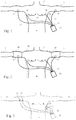
- Figure 1 is a block diagram illustrating the elements of a sensor arrangement for measuring a change in lung volume.
- An apparatus for impedance pneumography 30 is connected via a connector interface 31 to the sensor 11 attached to the right arm 2 and the sensor 12 attached to the left arm 3 of a human body 1.
- Sensors 21, 23 are attached to the side of thorax or to the midaxillary line on both sides of the body 1.
- the sensor element comprises an electrode and a cable 13, 14, 15, 16 conducting the electrical signal to the connector interface 31.
- the midaxillary line is defined as a coronal line on the torso between the anterior axillary line and the posterior axillary line. The sensor placement may vary few centimetres from the midaxillary line.
- Sensors 11, 12, 21, 22, cables, 13, 14, 15, 16, the interface 31 and the apparatus 30 are components of an impedance pneumography measurement system.
- the sensors 11, 12, 21, 22 may comprise a text, colour or other indication that helps the person using the impedance pneumography system to connect the sensor to a correct position on the body 1.
- Sleeves 41, 41 may comprise an indication separating the left arm 2 and the right arm 3. Also the sizing or the form of the sleeve 41, 42 may prevent the user from installing the sensor 11, 12 to a wrong position.
- the interface 31 configured to the apparatus 30 is arranged to comprise indication of a correct installation procedure, such as colour coding or text.
- the apparatus 30 may also comprise a display for informing the user about the procedure.
- the software implemented in the apparatus 30 may also comprise code for providing assistive information to the user, confirming the correct installation procedure or informing about any errors during the installation or operation.
- One example of an error situation is the measurement data being out of the predefined range.
- the computer program code comprises means for detecting the correct sensor 11, 12, 21, 22 being installed into the correct interface 31.
- the sensor may be configured to send information about the purpose or position in the interface 31 or the interface may have means for detecting the inserted sensor cable 13, 14, 15, 16.
- the apparatus 30 may comprise an interface to transmit the impedance pneumography information to another device, such as a computer or another medical device.
- the apparatus 30 is arranged to convert changes in thoracic impedance resulting from respiration into a high level respiration signal that can be used with other applications.
- the apparatus 30 may also be integrated into another medical device.
- Figure 2 illustrates one example where sensors 11, 12 are arranged to be part of a sleeve 41, 42.
- the sleeve 41, 42 is made from electrically resistive material that prevents the direct skin contact between the arm 2, 3 and the torso. This prevents the electrical current from passing through the skin and thus contributing to false values.
- the bioimpedance values are measured through the high-axillary line or from the preferred path of the upper portion of lungs.
- the sleeve may also be part of a shirt or jacket 43 arranged to be used with the impedance pneumography system.
- the sleeve may also be in the form of an armband. In one embodiment the thickness of the armband keeps the arm at a distance from the body.
- the sleeve may also comprise the electrode configured as a fabric electrode made of suitable material such as silver or platinum.
- Sensors 11, 12, 21, 22 may be arranged in different configurations.
- four electrodes are used; two for feeding an alternating current of a constant amplitude and two for sensing the voltage.
- a constant voltage may be used while the current is measured.
- the electrode is measuring for example the voltage differential measured from both arms or the electrodes may be feeding the current to enable measuring of the impedance.
- the pair of electrodes purposed for the same parameter is always positioned to a distance from each other.
- electrodes feeding the current may be positioned to different arms. Alternatively one may be positioned to the arm and the other to the side of the thorax on the opposite side of the body, as illustrated in Figure 3 . Feeding the current and measuring the voltage may also be combined into a single sensor as a pair of electrodes.
- Electrodes 11, 12 on the arms 2, 3 improves significantly the linearity of the measurement results on a ⁇ Z/ ⁇ V scale, especially at low lung volumes.
- One exemplary placement of the electrodes is between biceps and triceps brachii muscles. This placement of the electrodes on the arms can be described as placement on the supra-axillary line. Preventing the skin contact between the arms and the sides improves the measurement as the skin contact is not contributing to the bioimpedance value.
- the improved linearity may result from the technical features and physiological features such as the motion and shape change of the thorax and thoracic organs, particularly the diaphragm and the liver, and small airway closing and alveolar collapse.
- the diaphragm and liver reside more cephalad (headward) and, thus, are closer to the sensitivity field of the recording electrodes. This could be attributed to the finding that the ⁇ Z/ ⁇ V nonlinearity occurs in deep exhales only in the infra-axillary electrode locations. Small airway closure and possibly alveolar collapse occur even in healthy young subjects when the lung volume is lowered below the FRC level.
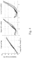
- FIG. 4 Examples of the improved ⁇ Z/ ⁇ V nonlinearity are illustrated in Figure 4 .
- the impedance versus lung volume has been measured using the three different sensor placements or electrode configurations referred to as supra-axillary, high infra-axillary and low infra-axillary.
- the plotted signals include the complete measurement sequence with six vital capacity manoeuvres (VCM) and multiple tidal breaths. The effect is clearly visible especially in low lung volumes.
- VCM vital capacity manoeuvres
- Figure 5 illustrates a generic example of a bioimpedance measurement arrangement.
- the lead field theory is applicable to bioimpedance measurements.
- two terminals act as the current source and sink and the other two as differential voltage pickup terminals.
- the lead field lines are illustrated in Figure 5 as dotted lines.
- the current and the voltage lead fields can be treated as a matrix dot product, being a commutative mathematical operation.
- the sensitivity field of the electrode configuration is formed by the dot product of the two lead fields.
- the voltage sensing and current feeding electrodes can be interchanged without affecting the measurement result.
- the absolute value of the sensitivity field resulting from the dot product varies in magnitude from point to point in a conductor, but the sign of the value can also change.
- the angle of the lead fields is equal to 90°; area 52; the sensitivity value is zero.
- area 53 the value turns negative.
- the measurement value is positively affected when the sensitivity lead lines are parallel; area 51. Therefore the components affecting the overall result are in the area where the two lead fields overlap.
- Figure 6 illustrates the lead field effect in a simplified form.
- lead fields overlap in the area 61.
- the majority of the parallel lines occur in the same area as the lungs or the upper portion of the lungs.
- the resulting effect is that the variable component of the derived signal is obtained mostly from the most important area.
- the present invention enables more sophisticated clinical applications of impedance pneumography, particularly in paediatric applications where the comfort and non-invasiveness of the method contribute largely to the behaviour of the patient.
- the apparatus can be kept simple and portable.
- One example is a respiration monitoring device which collects data in a convenient environment such as the patient's home. Parents may apply the impedance pneumography system according to the invention with their children.
- the collected data may be stored to the memory of the apparatus or it may be transmitted to another location by means known in the prior art.
- the data may comprise the respiratory rate, lung volumes as a function of time or in different environments such as during the sleep.
Landscapes
- Health & Medical Sciences (AREA)
- Life Sciences & Earth Sciences (AREA)
- Pulmonology (AREA)
- Engineering & Computer Science (AREA)
- General Health & Medical Sciences (AREA)
- Biophysics (AREA)
- Biomedical Technology (AREA)
- Heart & Thoracic Surgery (AREA)
- Medical Informatics (AREA)
- Molecular Biology (AREA)
- Surgery (AREA)
- Animal Behavior & Ethology (AREA)
- Physics & Mathematics (AREA)
- Public Health (AREA)
- Veterinary Medicine (AREA)
- Pathology (AREA)
- Physiology (AREA)
- Measurement And Recording Of Electrical Phenomena And Electrical Characteristics Of The Living Body (AREA)
- Hematology (AREA)
- Nuclear Medicine, Radiotherapy & Molecular Imaging (AREA)
- Radiology & Medical Imaging (AREA)
- Computer Networks & Wireless Communication (AREA)
- Artificial Intelligence (AREA)
- Computer Vision & Pattern Recognition (AREA)
- Psychiatry (AREA)
- Signal Processing (AREA)
- Measurement Of The Respiration, Hearing Ability, Form, And Blood Characteristics Of Living Organisms (AREA)
Description
- The invention relates to non-invasive lung volume measurement by impedance pneumography. More specifically, the invention relates to a method for measuring a change in lung volume.
- Impedance pneumography (IP) provides a minimally intrusive mode of measurement for lung volume changes. In the IP recording a small high frequency current is passed through a pair of skin electrodes and another pair of electrodes is used to record the generated voltage that is proportional to the impedance (Z), which again is proportional to the lung volume (V). The current feeding and voltage measurement may also be combined into a single pair of electrodes.
- Several studies have shown a linear relation between the thoracic impedance and the lung volume (ΔZ/ΔV) enabling an even pulmonary flow rate signal derivation, but the clinical applications of IP are still limited mainly to respiration rate and apnea detection in hospitalized patients. The emerging applications of IP in respiratory medicine use the measured signal to monitor the pulmonary flow and volume parameters related to airway obstruction during tidal breathing (TB). This places a strict requirement on the linearity between the measured thoracic impedance change (ΔZ) and the lung volume change (ΔV) throughout the complete lung volume range.
- In the prior art the impedance pneumography has been applied mostly with deep inspirations, excluding the deep expirations that would reduce the lung volume below the level of normal functional residual capacity (FRC). At low lung volumes the IP signal is highly nonlinear relative to the lung volume. The resting lung volume at which TB occurs, FRC, can change considerably due to many common factors, including supine posture, anatomical differences, mild obesity, and pathological conditions such as chronic obstructive pulmonary disease (COPD) and asthma. Thus, for the emerging IP applications that derive the pulmonary flow parameters, knowledge on the IP signal behaviour on the complete range of lung volume is important. The nonlinearity has been a factor reducing the clinical use of IP in flow measurement or in other uses more demanding than respiratory rate monitoring.
- The article "An electrical impedance spirometer" by E.S. Goldensohn and L.Zablow, Department of Neurology, College on Physicians and Surgeons, Columbia University, and the Neurological Institute, Presbyterian Hospital, New York City, 1958; discloses a sensor arrangement of two EKG-type electrodes on the wrists and two similar electrodes placed farther up on each arm.
- The article "Impedance pneumograph recording across the arms" by Gershon Weltman and Donald C. Ukkestad disclose a further study on measuring the respiratory signals across the arms, wherein all sensors are placed on the arms.
-
US2008/009757 discloses measuring the electrical impedance of sections of a living body. The measurement is carried out utilizing a plurality of electrodes each of which is disposed on a section of the living body, where the electrodes are capable of applying an electrical current through at least one probed section, and measure the electrical voltage over the probed section. - The invention discloses a method for measuring a change in lung volume according to
claim 1. - In one embodiment of the invention the skin contact between the arm and the torso is prevented by an insulation material configured to be positioned between the arm and the torso. The insulation material is made from a material known from its ability to insulate the electric current such as rubber or plastic. The material may be a hard object, such as a sheet of plastic positioned between the arm and the body, or it may have been formed to a shape to improve comfort. The insulation material may also be soft material; in one example the insulation material is configured to be a sleeve preventing the skin contact. The insulation material may also be configured to be a shirt or a vest preventing the skin contact.
- Another aspect presents a sensor arrangement for measuring a change in lung volume, comprising at least one electrode configured to be in contact with the arm of a human body and at least one electrode configured to be in skin contact with the thorax of a human body and transmitting measurement data to an apparatus for impedance pneumography. Said apparatus is for example purposed to measure a change in the lung volume or it may be used in any other measurement method applying impedance pneumography. According to an example two electrodes are configured to be in contact with one arm of the human body and two electrodes are configured to be in skin contact with the thorax of the human body on the side opposite to the arm. According to an embodiment two electrodes are configured to be in contact with opposite arms of the human body and two electrodes are configured to be in skin contact with the thorax on opposite sides of the human body.
- According to one example the sensor is configured to be part of an insulation material preventing the skin contact between the arm and the torso. The insulation material may be configured to be a sleeve preventing the skin contact. The sleeve may be a separate sleeve or part of a shirt or any similar garment. The electrode may also be a fabric electrode configured to be inside the sleeve.
- Another example relates to an apparatus for measuring a change in lung volume by impedance pneumography, characterized by at least one processor and at least one memory including computer program code, the at least one memory and the computer program code arranged to, with the at least one processor, cause the apparatus at least to perform: receiving information from a sensor comprising at least one electrode for impedance pneumography configured to be in contact with the arm of a human body and at least one electrode configured to be in skin contact with the thorax of a human body.
- Another aspect presents a computer program product comprising a computer-readable medium bearing computer program code embodied therein for use with a computer, the computer program code comprising code for receiving information from a sensor comprising an electrode for impedance pneumography configured to be in contact with the arm of a human body.
- The present invention provides an improved linearity ΔZ/ΔV ratio over the complete lung volume range. The measurement is improved especially with low lung volumes, thus enabling detection of phenomena occurring in that range. The invention also improves the applicability of impedance pneumography in paediatric applications where the comfort of the patient is important.
- The accompanying drawings, which are included to provide a further understanding of the invention and constitute a part of this specification, illustrate embodiments of the invention and together with the description help to explain the principles of the invention. In the drawings:
-
Fig. 1 is a diagram illustrating the elements of a sensor arrangement for measuring a change in lung volume, -
Fig. 2 illustrates the sensor arrangement with a sleeve or a shirt, -
Fig. 3 illustrates an alternative example of the sensor arrangement, -
Fig. 4 illustrates examples of the improved ΔZ/ΔV nonlinearity, -
Fig. 5 illustrates a generic example of a bioimpedance measurement arrangement and the lead field theory, -
Fig. 6 illustrates the lead field effect according to the invention in a simplified form, -
Fig. 7a illustrates the measurement where all sensors are placed in the arms, and -
Fig. 7b illustrates the measurement with the sensor placement according to an embodiment of the present invention. - Reference will now be made in detail to the embodiments of the present invention, examples of which are illustrated in the accompanying drawings.
-
Figure 1 is a block diagram illustrating the elements of a sensor arrangement for measuring a change in lung volume. An apparatus forimpedance pneumography 30 is connected via aconnector interface 31 to thesensor 11 attached to theright arm 2 and thesensor 12 attached to theleft arm 3 of ahuman body 1.Sensors 21, 23 are attached to the side of thorax or to the midaxillary line on both sides of thebody 1. The sensor element comprises an electrode and acable connector interface 31. The midaxillary line is defined as a coronal line on the torso between the anterior axillary line and the posterior axillary line. The sensor placement may vary few centimetres from the midaxillary line. -
Sensors interface 31 and theapparatus 30 are components of an impedance pneumography measurement system. Thesensors body 1. Sleeves 41, 41 may comprise an indication separating theleft arm 2 and theright arm 3. Also the sizing or the form of thesleeve sensor - In one example the
interface 31 configured to theapparatus 30 is arranged to comprise indication of a correct installation procedure, such as colour coding or text. Theapparatus 30 may also comprise a display for informing the user about the procedure. The software implemented in theapparatus 30 may also comprise code for providing assistive information to the user, confirming the correct installation procedure or informing about any errors during the installation or operation. One example of an error situation is the measurement data being out of the predefined range. - In one example the computer program code comprises means for detecting the
correct sensor correct interface 31. The sensor may be configured to send information about the purpose or position in theinterface 31 or the interface may have means for detecting the insertedsensor cable - The
apparatus 30 may comprise an interface to transmit the impedance pneumography information to another device, such as a computer or another medical device. In one embodiment theapparatus 30 is arranged to convert changes in thoracic impedance resulting from respiration into a high level respiration signal that can be used with other applications. Theapparatus 30 may also be integrated into another medical device. -
Figure 2 illustrates one example wheresensors sleeve sleeve arm jacket 43 arranged to be used with the impedance pneumography system. The sleeve may also be in the form of an armband. In one embodiment the thickness of the armband keeps the arm at a distance from the body. The sleeve may also comprise the electrode configured as a fabric electrode made of suitable material such as silver or platinum. -
Sensors Figure 3 . Feeding the current and measuring the voltage may also be combined into a single sensor as a pair of electrodes. - In impedance pneumography a small high frequency current is passed through a pair of skin electrodes and another pair of electrodes is used to record the generated voltage that is proportional to the impedance (Z), which again is proportional to the lung volume (V). The cardiogenic oscillations can be removed by a filtering technique described in the Finnish patent application
FI20115110 - Placing the
electrodes arms - The improved linearity may result from the technical features and physiological features such as the motion and shape change of the thorax and thoracic organs, particularly the diaphragm and the liver, and small airway closing and alveolar collapse. After a deep exhale, and generally in lowered FRC, the diaphragm and liver reside more cephalad (headward) and, thus, are closer to the sensitivity field of the recording electrodes. This could be attributed to the finding that the ΔZ/ΔV nonlinearity occurs in deep exhales only in the infra-axillary electrode locations. Small airway closure and possibly alveolar collapse occur even in healthy young subjects when the lung volume is lowered below the FRC level. As the lung volume decreases, the smaller, intraparenchumal airways decrease in calibre until they close at low lung volume. During exhalation in an upright posture, this closure occurs predominantly and earlier in the lower part of the lung. As airway closure and alveolar collapse are known to affect the electrical impedance of the lung, this could partially explain why the infra-axillary configurations exhibit the presented ΔZ/ΔV nonlinearity.
- Examples of the improved ΔZ/ΔV nonlinearity are illustrated in
Figure 4 . The impedance versus lung volume has been measured using the three different sensor placements or electrode configurations referred to as supra-axillary, high infra-axillary and low infra-axillary. The plotted signals include the complete measurement sequence with six vital capacity manoeuvres (VCM) and multiple tidal breaths. The effect is clearly visible especially in low lung volumes. - The effect of the present invention may also be explained using the lead field theory.
Figure 5 illustrates a generic example of a bioimpedance measurement arrangement. The lead field theory is applicable to bioimpedance measurements. In a conventional four-terminal (tetrapolar) impedance measurement two terminals act as the current source and sink and the other two as differential voltage pickup terminals. The lead field lines are illustrated inFigure 5 as dotted lines. As explained in the Master of Science thesis, Bioimpedance in a wireless wearable device; Ville-Pekka Seppä 2007, Tampere University of Technology; the current and the voltage lead fields can be treated as a matrix dot product, being a commutative mathematical operation. The sensitivity field of the electrode configuration is formed by the dot product of the two lead fields. In theory, the voltage sensing and current feeding electrodes can be interchanged without affecting the measurement result. The absolute value of the sensitivity field resulting from the dot product varies in magnitude from point to point in a conductor, but the sign of the value can also change. When the angle of the lead fields is equal to 90°;area 52; the sensitivity value is zero. When the 90° angle is exceeded;area 53; the value turns negative. The measurement value is positively affected when the sensitivity lead lines are parallel;area 51. Therefore the components affecting the overall result are in the area where the two lead fields overlap. -
Figure 6 illustrates the lead field effect in a simplified form. According to the sensor placement according to the present invention, lead fields overlap in thearea 61. The majority of the parallel lines occur in the same area as the lungs or the upper portion of the lungs. The resulting effect is that the variable component of the derived signal is obtained mostly from the most important area. - The prior art knows solutions in which all four sensors measuring both the voltage and the current are placed on the arms. However, this arrangement does not provide optimal solution as the nonlinearity is still present. The improvement is illustrated in
Figures 7a and 7b , wherein the same test subject uses different sensor arrangements.Figure 7a illustrates the measurement according to the prior art, where all sensors are placed in the arms. The non-linearity is evident, as the measurement curves representing several breathing cycles are distributed to wide area.Figure 7b illustrates the measurement with the sensor placement according to an embodiment of the present invention. The measurement curves create a uniform pattern with reasonably linear results. - The present invention enables more sophisticated clinical applications of impedance pneumography, particularly in paediatric applications where the comfort and non-invasiveness of the method contribute largely to the behaviour of the patient. As the sensor placement is simple, also the apparatus can be kept simple and portable. One example is a respiration monitoring device which collects data in a convenient environment such as the patient's home. Parents may apply the impedance pneumography system according to the invention with their children. The collected data may be stored to the memory of the apparatus or it may be transmitted to another location by means known in the prior art. The data may comprise the respiratory rate, lung volumes as a function of time or in different environments such as during the sleep.
- The invention is defined by appended claims 1-4.
Claims (4)
- A method for measuring a change in lung volume, comprising:placing a first pair of electrodes (11, 12) in skin contact with opposite arms (2) of a human body (1) ;placing a second pair of electrodes (21, 22) in skin contact with the midaxillary line on opposite sides of the human body (1); andmeasuring a parameter for impedance pneumography by tetrapolar impedance measurement, comprising:feeding a current to the first pair of electrodes (11, 12) in contact with the opposite arms of the human body and measuring a voltage by the second pair of electrodes (21, 22) in skin contact with the midaxillary line on opposite sides of the human body (1), orfeeding a current to the second pair of electrodes (21, 22) in skin contact with the midaxillary line on opposite sides of the human body and measuring a voltage by the first pair of electrodes (11, 12) in contact with the opposite arms (2) of the human body (1).
- The method according to claim 1, comprising preventing the skin contact between the arm (2, 3) and a torso by an insulation material positioned between the arm (2, 3) and the torso.
- The method according to claim 2, wherein the insulation material is a sleeve (41, 42).
- The method according to claim 2, wherein the insulation material is a shirt (43) or a vest.
Applications Claiming Priority (2)
| Application Number | Priority Date | Filing Date | Title |
|---|---|---|---|
| FI20125376A FI124977B (en) | 2012-04-03 | 2012-04-03 | Measurement of lung volume changes with impedance pneumography |
| PCT/FI2013/050361 WO2013150185A1 (en) | 2012-04-03 | 2013-04-03 | Measuring lung volume changes by impedance pneumography |
Publications (3)
| Publication Number | Publication Date |
|---|---|
| EP2833788A1 EP2833788A1 (en) | 2015-02-11 |
| EP2833788A4 EP2833788A4 (en) | 2015-12-16 |
| EP2833788B1 true EP2833788B1 (en) | 2019-09-18 |
Family
ID=49300049
Family Applications (1)
| Application Number | Title | Priority Date | Filing Date |
|---|---|---|---|
| EP13773037.0A Active EP2833788B1 (en) | 2012-04-03 | 2013-04-03 | Measuring lung volume changes by impedance pneumography |
Country Status (6)
| Country | Link |
|---|---|
| US (1) | US10034620B2 (en) |
| EP (1) | EP2833788B1 (en) |
| DK (1) | DK2833788T3 (en) |
| ES (1) | ES2759791T3 (en) |
| FI (1) | FI124977B (en) |
| WO (1) | WO2013150185A1 (en) |
Families Citing this family (2)
| Publication number | Priority date | Publication date | Assignee | Title |
|---|---|---|---|---|
| JP2022500206A (en) * | 2018-09-07 | 2022-01-04 | レヴェニオ リサーチ オーワイ | Methods and devices for breathing measurement |
| US12303455B2 (en) * | 2020-08-03 | 2025-05-20 | Hill-Rom Services, Inc. | Therapeutic technique using electrical impedance spectroscopy |
Family Cites Families (12)
| Publication number | Priority date | Publication date | Assignee | Title |
|---|---|---|---|---|
| US3730173A (en) * | 1970-02-02 | 1973-05-01 | Ahldea Corp | Stimulation method and apparatus for attempting to return a physiological parameter of a patient to normal |
| GB9524968D0 (en) | 1995-12-06 | 1996-02-07 | Brown Brian H | Impedance pneumography |
| US8164464B2 (en) | 2005-03-24 | 2012-04-24 | Matos Jeffrey A | Method and system of aircraft pilot assessment |
| WO2005010640A2 (en) * | 2003-07-31 | 2005-02-03 | Dst Delta Segments Technology, Inc. | Noninvasive multi-channel monitoring of hemodynamic parameters |
| ITFI20030308A1 (en) * | 2003-12-03 | 2005-06-04 | Milior S P A | KNITTED FABRIC FOR MONITORING OF VITAL SIGNALS. |
| JP4296570B2 (en) * | 2003-12-08 | 2009-07-15 | 日本光電工業株式会社 | Vital telemeter |
| JP4408692B2 (en) | 2003-12-19 | 2010-02-03 | 富士通株式会社 | Communication device management program |
| CN101506798A (en) | 2006-03-22 | 2009-08-12 | 皇家飞利浦电子股份有限公司 | Respiration-gated cardiography |
| KR101572790B1 (en) * | 2008-06-19 | 2015-12-01 | 코닌클리케 필립스 엔.브이. | Wearable device and system for a tamper free electric stimulation of a body |
| US8888700B2 (en) * | 2010-04-19 | 2014-11-18 | Sotera Wireless, Inc. | Body-worn monitor for measuring respiratory rate |
| AU2011289159C1 (en) * | 2010-08-13 | 2015-12-10 | Respiratory Motion, Inc. | Devices and methods for respiratory variation monitoring by measurement of respiratory volumes, motion and variability |
| FI20115110A0 (en) | 2011-02-03 | 2011-02-03 | Ville-Pekka Seppae | Method for dividing a composite signal consisting of oscillating waveforms and a modulating signal |
-
2012
- 2012-04-03 FI FI20125376A patent/FI124977B/en active IP Right Grant
-
2013
- 2013-04-03 DK DK13773037T patent/DK2833788T3/en active
- 2013-04-03 WO PCT/FI2013/050361 patent/WO2013150185A1/en not_active Ceased
- 2013-04-03 ES ES13773037T patent/ES2759791T3/en active Active
- 2013-04-03 US US14/390,229 patent/US10034620B2/en active Active
- 2013-04-03 EP EP13773037.0A patent/EP2833788B1/en active Active
Non-Patent Citations (1)
| Title |
|---|
| None * |
Also Published As
| Publication number | Publication date |
|---|---|
| WO2013150185A1 (en) | 2013-10-10 |
| US10034620B2 (en) | 2018-07-31 |
| US20150051469A1 (en) | 2015-02-19 |
| ES2759791T3 (en) | 2020-05-12 |
| EP2833788A4 (en) | 2015-12-16 |
| DK2833788T3 (en) | 2019-12-09 |
| FI20125376L (en) | 2013-10-04 |
| EP2833788A1 (en) | 2015-02-11 |
| FI124977B (en) | 2015-04-15 |
Similar Documents
| Publication | Publication Date | Title |
|---|---|---|
| Cohen et al. | Comparison of impedance and inductance ventilation sensors on adults during breathing, motion, and simulated airway obstruction | |
| US12220222B2 (en) | Device and method for determining and/or monitoring the respiratory effort of a subject | |
| CN110035691B (en) | Method and apparatus for measuring sleep apnea | |
| Tarrant et al. | Comparative review of techniques for recording respiratory events at rest and during deglutition | |
| US20180271380A1 (en) | Respiration rate monitoring by multiparameter algorithm in a device including integrated belt sensor | |
| US20160135715A1 (en) | Method for respiratory measurement | |
| Młyńczak et al. | Impedance pneumography: Is it possible? | |
| Gargiulo et al. | Electro-resistive bands for non-invasive cardiac and respiration monitoring, a feasibility study | |
| JP7702552B2 (en) | Method and apparatus for measuring respiration - Patents.com | |
| WO2012107849A1 (en) | Nasal cannula with integrated thermal flow sensing | |
| JP6084361B2 (en) | Breath sensor | |
| Qiu et al. | A wearable bioimpedance chest patch for IoHT-connected respiration monitoring | |
| US10034620B2 (en) | Measuring lung volume changes by impedance pneumography | |
| Li et al. | Thoracic impedance measurement for lung function evaluation | |
| Areekath et al. | An electric-field based breathing rate monitor | |
| Kuo et al. | Using ECG surface electrodes in measurement of respiration rate for preterm infants | |
| JP2024506439A (en) | Apparatus and method for outputting electrocardiogram signals and respiratory signals | |
| Karita et al. | Respiration monitoring during 6 min walk using wearable sensor measuring capacitance built across skin | |
| Sivayogan | Design and development of a contactless planar capacitive sensor | |
| CN115211837B (en) | A non-invasive monitoring method of lung function status based on dielectric constant measurement | |
| Leonov et al. | Lung volumes and ventilation assessment using multifrequency pioimpedance meter | |
| JP6639787B2 (en) | How to measure respiration | |
| Mäntylä | Feasibility of Continuous Respiratory Volume Monitoring with Indirect Measurements | |
| Hyttinen | MILLA JAUHIAINEN VALIDATION OF IMPEDANCE PNEUMOGRAPHY MEASURE-MENT FOR ASSESSMENT OF RESPIRATION IN CARDIOTHO-RACIC SURGERY PATIENTS | |
| NEUMAN | Cardiopulmonary monitoring |
Legal Events
| Date | Code | Title | Description |
|---|---|---|---|
| PUAI | Public reference made under article 153(3) epc to a published international application that has entered the european phase |
Free format text: ORIGINAL CODE: 0009012 |
|
| 17P | Request for examination filed |
Effective date: 20141027 |
|
| AK | Designated contracting states |
Kind code of ref document: A1 Designated state(s): AL AT BE BG CH CY CZ DE DK EE ES FI FR GB GR HR HU IE IS IT LI LT LU LV MC MK MT NL NO PL PT RO RS SE SI SK SM TR |
|
| AX | Request for extension of the european patent |
Extension state: BA ME |
|
| RAP1 | Party data changed (applicant data changed or rights of an application transferred) |
Owner name: TIDE MEDICAL OY |
|
| DAX | Request for extension of the european patent (deleted) | ||
| RA4 | Supplementary search report drawn up and despatched (corrected) |
Effective date: 20151117 |
|
| RIC1 | Information provided on ipc code assigned before grant |
Ipc: A61B 5/085 20060101ALI20151111BHEP Ipc: A61B 5/091 20060101ALI20151111BHEP Ipc: A61B 5/053 20060101ALI20151111BHEP Ipc: A61B 5/08 20060101AFI20151111BHEP Ipc: A61B 5/00 20060101ALI20151111BHEP |
|
| STAA | Information on the status of an ep patent application or granted ep patent |
Free format text: STATUS: EXAMINATION IS IN PROGRESS |
|
| 17Q | First examination report despatched |
Effective date: 20170607 |
|
| GRAP | Despatch of communication of intention to grant a patent |
Free format text: ORIGINAL CODE: EPIDOSNIGR1 |
|
| STAA | Information on the status of an ep patent application or granted ep patent |
Free format text: STATUS: GRANT OF PATENT IS INTENDED |
|
| INTG | Intention to grant announced |
Effective date: 20190412 |
|
| GRAS | Grant fee paid |
Free format text: ORIGINAL CODE: EPIDOSNIGR3 |
|
| GRAA | (expected) grant |
Free format text: ORIGINAL CODE: 0009210 |
|
| STAA | Information on the status of an ep patent application or granted ep patent |
Free format text: STATUS: THE PATENT HAS BEEN GRANTED |
|
| RIN1 | Information on inventor provided before grant (corrected) |
Inventor name: SEPPAE, VILLE-PEKKA Inventor name: VIIK, JARI |
|
| AK | Designated contracting states |
Kind code of ref document: B1 Designated state(s): AL AT BE BG CH CY CZ DE DK EE ES FI FR GB GR HR HU IE IS IT LI LT LU LV MC MK MT NL NO PL PT RO RS SE SI SK SM TR |
|
| REG | Reference to a national code |
Ref country code: GB Ref legal event code: FG4D |
|
| REG | Reference to a national code |
Ref country code: CH Ref legal event code: EP |
|
| REG | Reference to a national code |
Ref country code: DE Ref legal event code: R096 Ref document number: 602013060711 Country of ref document: DE |
|
| REG | Reference to a national code |
Ref country code: AT Ref legal event code: REF Ref document number: 1180349 Country of ref document: AT Kind code of ref document: T Effective date: 20191015 |
|
| REG | Reference to a national code |
Ref country code: IE Ref legal event code: FG4D |
|
| REG | Reference to a national code |
Ref country code: DK Ref legal event code: T3 Effective date: 20191204 |
|
| REG | Reference to a national code |
Ref country code: CH Ref legal event code: NV Representative=s name: NOVAGRAAF INTERNATIONAL SA, CH |
|
| REG | Reference to a national code |
Ref country code: NL Ref legal event code: FP |
|
| PG25 | Lapsed in a contracting state [announced via postgrant information from national office to epo] |
Ref country code: FI Free format text: LAPSE BECAUSE OF FAILURE TO SUBMIT A TRANSLATION OF THE DESCRIPTION OR TO PAY THE FEE WITHIN THE PRESCRIBED TIME-LIMIT Effective date: 20190918 Ref country code: HR Free format text: LAPSE BECAUSE OF FAILURE TO SUBMIT A TRANSLATION OF THE DESCRIPTION OR TO PAY THE FEE WITHIN THE PRESCRIBED TIME-LIMIT Effective date: 20190918 Ref country code: LT Free format text: LAPSE BECAUSE OF FAILURE TO SUBMIT A TRANSLATION OF THE DESCRIPTION OR TO PAY THE FEE WITHIN THE PRESCRIBED TIME-LIMIT Effective date: 20190918 Ref country code: NO Free format text: LAPSE BECAUSE OF FAILURE TO SUBMIT A TRANSLATION OF THE DESCRIPTION OR TO PAY THE FEE WITHIN THE PRESCRIBED TIME-LIMIT Effective date: 20191218 Ref country code: BG Free format text: LAPSE BECAUSE OF FAILURE TO SUBMIT A TRANSLATION OF THE DESCRIPTION OR TO PAY THE FEE WITHIN THE PRESCRIBED TIME-LIMIT Effective date: 20191218 Ref country code: SE Free format text: LAPSE BECAUSE OF FAILURE TO SUBMIT A TRANSLATION OF THE DESCRIPTION OR TO PAY THE FEE WITHIN THE PRESCRIBED TIME-LIMIT Effective date: 20190918 |
|
| REG | Reference to a national code |
Ref country code: SE Ref legal event code: TRGR |
|
| REG | Reference to a national code |
Ref country code: LT Ref legal event code: MG4D |
|
| PG25 | Lapsed in a contracting state [announced via postgrant information from national office to epo] |
Ref country code: GR Free format text: LAPSE BECAUSE OF FAILURE TO SUBMIT A TRANSLATION OF THE DESCRIPTION OR TO PAY THE FEE WITHIN THE PRESCRIBED TIME-LIMIT Effective date: 20191219 Ref country code: RS Free format text: LAPSE BECAUSE OF FAILURE TO SUBMIT A TRANSLATION OF THE DESCRIPTION OR TO PAY THE FEE WITHIN THE PRESCRIBED TIME-LIMIT Effective date: 20190918 Ref country code: LV Free format text: LAPSE BECAUSE OF FAILURE TO SUBMIT A TRANSLATION OF THE DESCRIPTION OR TO PAY THE FEE WITHIN THE PRESCRIBED TIME-LIMIT Effective date: 20190918 Ref country code: AL Free format text: LAPSE BECAUSE OF FAILURE TO SUBMIT A TRANSLATION OF THE DESCRIPTION OR TO PAY THE FEE WITHIN THE PRESCRIBED TIME-LIMIT Effective date: 20190918 |
|
| PG25 | Lapsed in a contracting state [announced via postgrant information from national office to epo] |
Ref country code: EE Free format text: LAPSE BECAUSE OF FAILURE TO SUBMIT A TRANSLATION OF THE DESCRIPTION OR TO PAY THE FEE WITHIN THE PRESCRIBED TIME-LIMIT Effective date: 20190918 Ref country code: PL Free format text: LAPSE BECAUSE OF FAILURE TO SUBMIT A TRANSLATION OF THE DESCRIPTION OR TO PAY THE FEE WITHIN THE PRESCRIBED TIME-LIMIT Effective date: 20190918 Ref country code: PT Free format text: LAPSE BECAUSE OF FAILURE TO SUBMIT A TRANSLATION OF THE DESCRIPTION OR TO PAY THE FEE WITHIN THE PRESCRIBED TIME-LIMIT Effective date: 20200120 Ref country code: RO Free format text: LAPSE BECAUSE OF FAILURE TO SUBMIT A TRANSLATION OF THE DESCRIPTION OR TO PAY THE FEE WITHIN THE PRESCRIBED TIME-LIMIT Effective date: 20190918 |
|
| REG | Reference to a national code |
Ref country code: ES Ref legal event code: FG2A Ref document number: 2759791 Country of ref document: ES Kind code of ref document: T3 Effective date: 20200512 |
|
| PG25 | Lapsed in a contracting state [announced via postgrant information from national office to epo] |
Ref country code: SM Free format text: LAPSE BECAUSE OF FAILURE TO SUBMIT A TRANSLATION OF THE DESCRIPTION OR TO PAY THE FEE WITHIN THE PRESCRIBED TIME-LIMIT Effective date: 20190918 Ref country code: SK Free format text: LAPSE BECAUSE OF FAILURE TO SUBMIT A TRANSLATION OF THE DESCRIPTION OR TO PAY THE FEE WITHIN THE PRESCRIBED TIME-LIMIT Effective date: 20190918 Ref country code: IS Free format text: LAPSE BECAUSE OF FAILURE TO SUBMIT A TRANSLATION OF THE DESCRIPTION OR TO PAY THE FEE WITHIN THE PRESCRIBED TIME-LIMIT Effective date: 20200224 Ref country code: CZ Free format text: LAPSE BECAUSE OF FAILURE TO SUBMIT A TRANSLATION OF THE DESCRIPTION OR TO PAY THE FEE WITHIN THE PRESCRIBED TIME-LIMIT Effective date: 20190918 |
|
| REG | Reference to a national code |
Ref country code: DE Ref legal event code: R097 Ref document number: 602013060711 Country of ref document: DE |
|
| REG | Reference to a national code |
Ref country code: SE Ref legal event code: TRGR |
|
| PLBE | No opposition filed within time limit |
Free format text: ORIGINAL CODE: 0009261 |
|
| STAA | Information on the status of an ep patent application or granted ep patent |
Free format text: STATUS: NO OPPOSITION FILED WITHIN TIME LIMIT |
|
| PG2D | Information on lapse in contracting state deleted |
Ref country code: IS |
|
| PG25 | Lapsed in a contracting state [announced via postgrant information from national office to epo] |
Ref country code: IS Free format text: LAPSE BECAUSE OF FAILURE TO SUBMIT A TRANSLATION OF THE DESCRIPTION OR TO PAY THE FEE WITHIN THE PRESCRIBED TIME-LIMIT Effective date: 20200119 |
|
| 26N | No opposition filed |
Effective date: 20200619 |
|
| PG25 | Lapsed in a contracting state [announced via postgrant information from national office to epo] |
Ref country code: SI Free format text: LAPSE BECAUSE OF FAILURE TO SUBMIT A TRANSLATION OF THE DESCRIPTION OR TO PAY THE FEE WITHIN THE PRESCRIBED TIME-LIMIT Effective date: 20190918 |
|
| PG25 | Lapsed in a contracting state [announced via postgrant information from national office to epo] |
Ref country code: MC Free format text: LAPSE BECAUSE OF FAILURE TO SUBMIT A TRANSLATION OF THE DESCRIPTION OR TO PAY THE FEE WITHIN THE PRESCRIBED TIME-LIMIT Effective date: 20190918 |
|
| PG25 | Lapsed in a contracting state [announced via postgrant information from national office to epo] |
Ref country code: LU Free format text: LAPSE BECAUSE OF NON-PAYMENT OF DUE FEES Effective date: 20200403 |
|
| REG | Reference to a national code |
Ref country code: AT Ref legal event code: UEP Ref document number: 1180349 Country of ref document: AT Kind code of ref document: T Effective date: 20190918 |
|
| PG25 | Lapsed in a contracting state [announced via postgrant information from national office to epo] |
Ref country code: IE Free format text: LAPSE BECAUSE OF NON-PAYMENT OF DUE FEES Effective date: 20200403 |
|
| PG25 | Lapsed in a contracting state [announced via postgrant information from national office to epo] |
Ref country code: TR Free format text: LAPSE BECAUSE OF FAILURE TO SUBMIT A TRANSLATION OF THE DESCRIPTION OR TO PAY THE FEE WITHIN THE PRESCRIBED TIME-LIMIT Effective date: 20190918 Ref country code: MT Free format text: LAPSE BECAUSE OF FAILURE TO SUBMIT A TRANSLATION OF THE DESCRIPTION OR TO PAY THE FEE WITHIN THE PRESCRIBED TIME-LIMIT Effective date: 20190918 Ref country code: CY Free format text: LAPSE BECAUSE OF FAILURE TO SUBMIT A TRANSLATION OF THE DESCRIPTION OR TO PAY THE FEE WITHIN THE PRESCRIBED TIME-LIMIT Effective date: 20190918 |
|
| PG25 | Lapsed in a contracting state [announced via postgrant information from national office to epo] |
Ref country code: MK Free format text: LAPSE BECAUSE OF FAILURE TO SUBMIT A TRANSLATION OF THE DESCRIPTION OR TO PAY THE FEE WITHIN THE PRESCRIBED TIME-LIMIT Effective date: 20190918 |
|
| PGFP | Annual fee paid to national office [announced via postgrant information from national office to epo] |
Ref country code: NL Payment date: 20250422 Year of fee payment: 13 |
|
| PGFP | Annual fee paid to national office [announced via postgrant information from national office to epo] |
Ref country code: DE Payment date: 20250421 Year of fee payment: 13 |
|
| PGFP | Annual fee paid to national office [announced via postgrant information from national office to epo] |
Ref country code: DK Payment date: 20250429 Year of fee payment: 13 |
|
| PGFP | Annual fee paid to national office [announced via postgrant information from national office to epo] |
Ref country code: BE Payment date: 20250417 Year of fee payment: 13 Ref country code: IT Payment date: 20250424 Year of fee payment: 13 |
|
| PGFP | Annual fee paid to national office [announced via postgrant information from national office to epo] |
Ref country code: FR Payment date: 20250421 Year of fee payment: 13 |
|
| PGFP | Annual fee paid to national office [announced via postgrant information from national office to epo] |
Ref country code: CH Payment date: 20250501 Year of fee payment: 13 |
|
| PGFP | Annual fee paid to national office [announced via postgrant information from national office to epo] |
Ref country code: AT Payment date: 20250417 Year of fee payment: 13 |
|
| PGFP | Annual fee paid to national office [announced via postgrant information from national office to epo] |
Ref country code: SE Payment date: 20250422 Year of fee payment: 13 |
|
| PGFP | Annual fee paid to national office [announced via postgrant information from national office to epo] |
Ref country code: ES Payment date: 20250728 Year of fee payment: 13 |
|
| PGFP | Annual fee paid to national office [announced via postgrant information from national office to epo] |
Ref country code: GB Payment date: 20260320 Year of fee payment: 14 |
|
| REG | Reference to a national code |
Ref country code: CH Ref legal event code: U11 Free format text: ST27 STATUS EVENT CODE: U-0-0-U10-U11 (AS PROVIDED BY THE NATIONAL OFFICE) Effective date: 20260501 |