EP2833569A1 - Device for automated signal capture and location based on real-time analysis of signal characteristics - Google Patents
Device for automated signal capture and location based on real-time analysis of signal characteristics Download PDFInfo
- Publication number
- EP2833569A1 EP2833569A1 EP14179266.3A EP14179266A EP2833569A1 EP 2833569 A1 EP2833569 A1 EP 2833569A1 EP 14179266 A EP14179266 A EP 14179266A EP 2833569 A1 EP2833569 A1 EP 2833569A1
- Authority
- EP
- European Patent Office
- Prior art keywords
- signal
- trigger
- location
- real
- measurement device
- Prior art date
- Legal status (The legal status is an assumption and is not a legal conclusion. Google has not performed a legal analysis and makes no representation as to the accuracy of the status listed.)
- Granted
Links
Images


Classifications
-
- G—PHYSICS
- G01—MEASURING; TESTING
- G01S—RADIO DIRECTION-FINDING; RADIO NAVIGATION; DETERMINING DISTANCE OR VELOCITY BY USE OF RADIO WAVES; LOCATING OR PRESENCE-DETECTING BY USE OF THE REFLECTION OR RERADIATION OF RADIO WAVES; ANALOGOUS ARRANGEMENTS USING OTHER WAVES
- G01S5/00—Position-fixing by co-ordinating two or more direction or position line determinations; Position-fixing by co-ordinating two or more distance determinations
- G01S5/02—Position-fixing by co-ordinating two or more direction or position line determinations; Position-fixing by co-ordinating two or more distance determinations using radio waves
- G01S5/10—Position of receiver fixed by co-ordinating a plurality of position lines defined by path-difference measurements, e.g. omega or decca systems
-
- H—ELECTRICITY
- H04—ELECTRIC COMMUNICATION TECHNIQUE
- H04B—TRANSMISSION
- H04B17/00—Monitoring; Testing
- H04B17/20—Monitoring; Testing of receivers
- H04B17/23—Indication means, e.g. displays, alarms, audible means
-
- H—ELECTRICITY
- H04—ELECTRIC COMMUNICATION TECHNIQUE
- H04B—TRANSMISSION
- H04B17/00—Monitoring; Testing
- H04B17/20—Monitoring; Testing of receivers
- H04B17/27—Monitoring; Testing of receivers for locating or positioning the transmitter
Definitions
- This disclosure relates to signal processing systems and, more particularly, to tools and techniques for performing real-time analysis of certain signal characteristics.
- the most commonly-used parameters such as relative location change (e.g., every x meters), time interval (e.g., every x seconds), and manual operation (e.g., whenever the user performs a click operation), are the only available senses with regard to the capture, measurement, and location of the signal (or signals) of interest.
- Certain embodiments of the disclosed technology are generally directed to methods by which signals can be detected and located using real-time signal analysis in conjunction with physical mapping functionality.
- Such embodiments may include mobile systems that are configured to perform automatic detection, measurement, and location (e.g., physical mapping, such as determining the geographic location/azimuth) of certain signals (e.g., rogue transmitters, interferers, standards violations) based on user-specified signal characteristics.
- Such systems may advantageously provide spectrum monitoring data that is dense in high-value targets.
- Certain embodiments of the disclosed technology are generally directed to methods by which real-time triggers can be qualified based on their physical location.
- Such embodiments may include real-time spectrum analyzers that can be configured to detect signals based on any of a number of real-time triggering capabilities such as frequency mask, signal density, and signal power, for example. Triggers such as these can be forwarded to a location-aware mapping function that can be optionally coupled with a directional antenna in order to capture and measure the detected signal and also to map the physical location of the signal. These triggers may be further qualified by a user-specified area of interest.
- Mobile systems in which real-time triggers can be generated based on signal content and physical location may be advantageously used for or in conjunction with spectral monitoring operations, such as the detection of rogue transmitters, interferers, and standards violations, for example.
- Embodiments of the disclosed technology are generally directed to tools and techniques by which general purpose, real-time signal discovery features, such as real-time triggers, for example, may be used to efficiently perform automated and efficient spectrum monitoring and signal location.
- general purpose, real-time signal discovery features such as real-time triggers, for example.
- location-based triggering in connection with spectrum monitoring instruments, may advantageously provide powerful triggering and signal capture capabilities for spectral monitoring operations.
- the power of a signal monitoring system may be significantly increased by adding the capability for initiating signal capture and measurement along with signal location information based on the real-time content of the signal itself.
- Signal discovery mechanisms available in real-time spectrum analyzers e.g., frequency mask trigger and DPX density trigger
- FIGURE 1 illustrates an example of an automated spectrum monitoring system 100 in accordance with certain embodiments of the disclosed technology.
- the system 100 includes a measurement instrument 110, e.g., a portable device, that may communicate with a network 150 and has a real-time trigger detector and location-aware measurement collection and mapping function.
- the measurement instrument 110 includes a signal information display portion 120 and a user interface 130.
- the entire system 100 is a mobile system.
- the system 100 can advantageously allow a user to navigate over an area to be monitored, e.g., using an active map window 131 of the user interface 130, while the system 100 automatically detects, captures, measures, and locates signals, e.g., from an RF input, based on real-time evaluation of one or more user-specified signal characteristics as well as the actual physical location of the measurement device, e.g., as determined or otherwise received from a GPS input.
- the system 100 is thus capable of collecting spectral content information that is directly aligned with the monitoring interests of the user.
- the measurement instrument 110 may optionally send location information to the network 150.
- the user interface 130 includes a user interaction window 132 that has multiple buttons 133-138 and a thumbnail portion 139 that displays a smaller version of the signal information that is concurrently presented by the signal information display portion 120. Selection of one of the buttons 133-138 may cause a certain type of trigger, such as a frequency mask trigger or a DPX density trigger, to be applied.
- the map window 131 may visually indicate the geographic location of the detected signal.
- FIGURE 2 illustrates an example 200 in which a frequency mask trigger is used to detect and locate rogue signals in accordance with certain embodiments of the disclosed technology.
- a frequency mask 240 specifying the authorized signals operating in the frequency band at the current location has been generated.
- Location-based masks, such as the frequency mask 240, of authorized signal transmissions can be automatically downloaded from one or more online source(s) 250 or optionally pre-loaded into the measurement instrument. Since the system in the example 200 is location-aware, such masks can be automatically updated as the location changes, thus further automating signal monitoring capabilities.
- Detected signals that are operating outside of the frequency mask 240 are deemed unauthorized or rogue signals and may be visually presented as such, e.g., using corresponding icons or other indicators, within the map window 131 of the user interface 130.
- the condition may be detected using the frequency mask trigger function and the location-based trigger qualification to determine whether a valid trigger has been generated.
- the resulting trigger is propagated to the mapping application, alerting it to obtain signal measurement data from the instrument and insert an indication of such into the active map 131 at the current location of the measurement instrument, e.g., using two icons 260 and 261 or other visual indicators.
- each of the icons 260 and 261 are thumbnail versions of the information that is concurrently presented by the signal information display portion 120.
- Additional information including, but not limited to, the azimuth of the signal transmission may also be obtained, e.g., from the receiving antenna, and represented on the active map 131 using a directional arrow. Collection of the azimuth information may support triangulation for more precise location of the rogue signal source. Thus, signals of interest may be discovered, captured, analyzed, and located by way of an automated operation that is based on user-specified signal criteria.
- a real-time spectrum analyzer In addition to frequency mask triggers, a real-time spectrum analyzer generally provides various other types of real-time triggers that can be used to detect signals. These triggers may also be used to provide signal capture, measure, and locate operations for spectrum monitoring.
- FIGURE 3 illustrates an example 300 in which a DPX density trigger is used to detect and locate one or more signals of interest in accordance with certain embodiments of the disclosed technology.
- the DPX density trigger is being used to detect a signal characteristic and initiate capture, measure, and locate operations such as those described above.
- the resulting trigger in the example 300 may be propagated to the mapping application, alerting it to obtain signal measurement data from the instrument and insert an indication of such into the active map 131 at the current location of the measurement instrument, e.g., using two icons 360 and 361, e.g., that are or include thumbnail versions of the information that is concurrently presented by the signal information display portion 120, or other visual indicators.
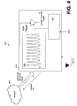
- FIGURE 4 illustrates an example of a location qualified trigger system 400 in accordance with certain embodiments of the disclosed technology.
- the system 400 is similar to the system 100 of FIGURES 1-3 in that the system 400 includes a measurement instrument 410, e.g., a portable device, that may communicate with a network 450 and includes a signal information display 420 and an active map window 431.
- the entire system 400 may be a mobile system.
- the system 400 can advantageously allow a user to navigate over an area to be monitored, e.g., using the active map window 431, while the system 400 automatically detects, captures, measures, and locates signals, e.g., from an RF input, based on real-time evaluation of one or more user-specified signal characteristics as well as the actual physical location of the measurement device, e.g., as determined or otherwise received from a GPS input.
- the measurement instrument 410 may optionally send detected signal location information to the network 450.
- the example 400 further includes a location qualified trigger based on an RSA trigger and the determined geographic location, e.g., from the GPS input.
Landscapes
- Physics & Mathematics (AREA)
- Engineering & Computer Science (AREA)
- Electromagnetism (AREA)
- Computer Networks & Wireless Communication (AREA)
- Signal Processing (AREA)
- General Physics & Mathematics (AREA)
- Radar, Positioning & Navigation (AREA)
- Remote Sensing (AREA)
- Position Fixing By Use Of Radio Waves (AREA)
Abstract
Description
- This disclosure relates to signal processing systems and, more particularly, to tools and techniques for performing real-time analysis of certain signal characteristics.
- Users engaged in spectrum monitoring generally have a need to discover, capture, analyze, and locate certain signals of interest. While instruments that are typically used today may be proficient in signal discovery, triggering, capture, and analysis, such instruments lack in support for signal location and, more generally, location awareness. While mapping functionality has been added to certain types of monitoring equipment to support GPS-based measurement location and mapping, initiation of signal capture, signal measurement, and determination of signal location is typically based on indicators that are not directly related to the signal of interest. The most commonly-used parameters, such as relative location change (e.g., every x meters), time interval (e.g., every x seconds), and manual operation (e.g., whenever the user performs a click operation), are the only available senses with regard to the capture, measurement, and location of the signal (or signals) of interest.
- Accordingly, a need remains for systems and methods configured to perform automated signal capture and location determination.
- Certain embodiments of the disclosed technology are generally directed to methods by which signals can be detected and located using real-time signal analysis in conjunction with physical mapping functionality. Such embodiments may include mobile systems that are configured to perform automatic detection, measurement, and location (e.g., physical mapping, such as determining the geographic location/azimuth) of certain signals (e.g., rogue transmitters, interferers, standards violations) based on user-specified signal characteristics. Such systems may advantageously provide spectrum monitoring data that is dense in high-value targets.
- Certain embodiments of the disclosed technology are generally directed to methods by which real-time triggers can be qualified based on their physical location. Such embodiments may include real-time spectrum analyzers that can be configured to detect signals based on any of a number of real-time triggering capabilities such as frequency mask, signal density, and signal power, for example. Triggers such as these can be forwarded to a location-aware mapping function that can be optionally coupled with a directional antenna in order to capture and measure the detected signal and also to map the physical location of the signal. These triggers may be further qualified by a user-specified area of interest. Mobile systems in which real-time triggers can be generated based on signal content and physical location may be advantageously used for or in conjunction with spectral monitoring operations, such as the detection of rogue transmitters, interferers, and standards violations, for example.
-
-
FIGURE 1 illustrates an example of an automated spectrum monitoring system in accordance with certain embodiments of the disclosed technology. -
FIGURE 2 illustrates an example in which a frequency mask trigger is used to detect and locate rogue signals in accordance with certain embodiments of the disclosed technology. -
FIGURE 3 illustrates an example in which a DPX density trigger is used to detect and locate one or more signals of interest in accordance with certain embodiments of the disclosed technology. -
FIGURE 4 illustrates an example of a location qualified trigger system in accordance with certain embodiments of the disclosed technology. - Embodiments of the disclosed technology are generally directed to tools and techniques by which general purpose, real-time signal discovery features, such as real-time triggers, for example, may be used to efficiently perform automated and efficient spectrum monitoring and signal location. The use of location-based triggering, in connection with spectrum monitoring instruments, may advantageously provide powerful triggering and signal capture capabilities for spectral monitoring operations.
- The power of a signal monitoring system may be significantly increased by adding the capability for initiating signal capture and measurement along with signal location information based on the real-time content of the signal itself. Signal discovery mechanisms available in real-time spectrum analyzers (e.g., frequency mask trigger and DPX density trigger), when used in conjunction with a location-aware mapping function, may advantageously provide the functionality necessary to determine when to initiate signal measurement and determination of the signal location based on the actual signal characteristics that the user is interested in detecting.
-
FIGURE 1 illustrates an example of an automatedspectrum monitoring system 100 in accordance with certain embodiments of the disclosed technology. In the example, thesystem 100 includes ameasurement instrument 110, e.g., a portable device, that may communicate with anetwork 150 and has a real-time trigger detector and location-aware measurement collection and mapping function. In the example, themeasurement instrument 110 includes a signalinformation display portion 120 and auser interface 130. In certain embodiments, theentire system 100 is a mobile system. - The
system 100 can advantageously allow a user to navigate over an area to be monitored, e.g., using anactive map window 131 of theuser interface 130, while thesystem 100 automatically detects, captures, measures, and locates signals, e.g., from an RF input, based on real-time evaluation of one or more user-specified signal characteristics as well as the actual physical location of the measurement device, e.g., as determined or otherwise received from a GPS input. Thesystem 100 is thus capable of collecting spectral content information that is directly aligned with the monitoring interests of the user. Further, themeasurement instrument 110 may optionally send location information to thenetwork 150. - In the example, the
user interface 130 includes auser interaction window 132 that has multiple buttons 133-138 and athumbnail portion 139 that displays a smaller version of the signal information that is concurrently presented by the signalinformation display portion 120. Selection of one of the buttons 133-138 may cause a certain type of trigger, such as a frequency mask trigger or a DPX density trigger, to be applied. Themap window 131 may visually indicate the geographic location of the detected signal. -
FIGURE 2 illustrates an example 200 in which a frequency mask trigger is used to detect and locate rogue signals in accordance with certain embodiments of the disclosed technology. In the example, afrequency mask 240 specifying the authorized signals operating in the frequency band at the current location has been generated. Location-based masks, such as thefrequency mask 240, of authorized signal transmissions can be automatically downloaded from one or more online source(s) 250 or optionally pre-loaded into the measurement instrument. Since the system in the example 200 is location-aware, such masks can be automatically updated as the location changes, thus further automating signal monitoring capabilities. - Detected signals that are operating outside of the
frequency mask 240 are deemed unauthorized or rogue signals and may be visually presented as such, e.g., using corresponding icons or other indicators, within themap window 131 of theuser interface 130. The condition may be detected using the frequency mask trigger function and the location-based trigger qualification to determine whether a valid trigger has been generated. - In the example 200, there are two signals operating outside the authorization mask. The resulting trigger is propagated to the mapping application, alerting it to obtain signal measurement data from the instrument and insert an indication of such into the
active map 131 at the current location of the measurement instrument, e.g., using twoicons icons information display portion 120. - Additional information including, but not limited to, the azimuth of the signal transmission may also be obtained, e.g., from the receiving antenna, and represented on the
active map 131 using a directional arrow. Collection of the azimuth information may support triangulation for more precise location of the rogue signal source. Thus, signals of interest may be discovered, captured, analyzed, and located by way of an automated operation that is based on user-specified signal criteria. - In addition to frequency mask triggers, a real-time spectrum analyzer generally provides various other types of real-time triggers that can be used to detect signals. These triggers may also be used to provide signal capture, measure, and locate operations for spectrum monitoring.
-
FIGURE 3 illustrates an example 300 in which a DPX density trigger is used to detect and locate one or more signals of interest in accordance with certain embodiments of the disclosed technology. In the example, the DPX density trigger is being used to detect a signal characteristic and initiate capture, measure, and locate operations such as those described above. - As with the example 200 of
FIGURE 2 , the resulting trigger in the example 300 may be propagated to the mapping application, alerting it to obtain signal measurement data from the instrument and insert an indication of such into theactive map 131 at the current location of the measurement instrument, e.g., using twoicons information display portion 120, or other visual indicators. -
FIGURE 4 illustrates an example of a locationqualified trigger system 400 in accordance with certain embodiments of the disclosed technology. Thesystem 400 is similar to thesystem 100 ofFIGURES 1-3 in that thesystem 400 includes ameasurement instrument 410, e.g., a portable device, that may communicate with anetwork 450 and includes asignal information display 420 and anactive map window 431. As with thesystem 100 ofFIGURES 1-3 , theentire system 400 may be a mobile system. - The
system 400 can advantageously allow a user to navigate over an area to be monitored, e.g., using theactive map window 431, while thesystem 400 automatically detects, captures, measures, and locates signals, e.g., from an RF input, based on real-time evaluation of one or more user-specified signal characteristics as well as the actual physical location of the measurement device, e.g., as determined or otherwise received from a GPS input. Themeasurement instrument 410 may optionally send detected signal location information to thenetwork 450. The example 400 further includes a location qualified trigger based on an RSA trigger and the determined geographic location, e.g., from the GPS input. - Having described and illustrated the principles of the invention with reference to illustrated embodiments, it will be recognized that the illustrated embodiments may be modified in arrangement and detail without departing from such principles, and may be combined in any desired manner. And although the foregoing discussion has focused on particular embodiments, other configurations are contemplated. In particular, even though expressions such as "according to an embodiment of the invention" or the like are used herein, these phrases are meant to generally reference embodiment possibilities, and are not intended to limit the invention to particular embodiment configurations. As used herein, these terms may reference the same or different embodiments that are combinable into other embodiments.
- Consequently, in view of the wide variety of permutations to the embodiments described herein, this detailed description and accompanying material is intended to be illustrative only, and should not be taken as limiting the scope of the invention.
Claims (15)
- An automated spectrum monitoring system, comprising:a measurement device having:a signal information display configured to visually present signal information pertaining to a signal;a real-time trigger detector configured to detect a trigger corresponding to the signal; anda mapping application configured to determine a geographic location of a source of the signal and visually present an indication of the geographic location.
- The system of claim 1, further comprising:an RF input configured to provide the signal to the measurement device; and/ora GPS input configured to provide an indication of a current physical location of the measurement device.
- The system of claim 1 or 2, in which the mapping application is further configured to allow a user to navigate over a geographic area to be monitored.
- The system of any preceding claim, in which the signal information includes a measured strength of the signal.
- The system of any preceding claim, in which the trigger is:specified by a user; and/ora frequency mask trigger.
- The system of claim 5, in which the frequency mask trigger is used to detect and locate at least one rogue signal.
- The system of claim 6, in which the at least one rogue signal is operating outside of the frequency mask.
- The system of any of claims 1-4, in which the trigger is a DPX density trigger.
- The system of claim 8, in which the DPX density trigger is used to detect and locate at least one rogue signal.
- The system of any preceding claim, in which the real-time trigger detector is configured to detect the trigger based on application of a location-based mask of authorized transmissions.
- The system of claim 10, in which the location-based mask of authorized transmissions is automatically downloaded from a network.
- The system of any preceding claim, further comprising a network configured to receive from the measurement device:the geographic location of the signal source; and/orthe physical location of the measurement device.
- The system of any preceding claim, further comprising a trigger qualifying mechanism configured to qualify a trigger based on the geographic location of the signal source.
- The system of any preceding claim, further comprising a receiving antenna configured to provide an azimuth of the signal.
- The system of claim 14, in which the mapping application is further configured to visually present the azimuth of the signal.
Applications Claiming Priority (1)
| Application Number | Priority Date | Filing Date | Title |
|---|---|---|---|
| US13/957,189 US8923894B1 (en) | 2013-08-01 | 2013-08-01 | Device for automated signal capture and location based on real-time analysis of signal characteristics |
Publications (2)
| Publication Number | Publication Date |
|---|---|
| EP2833569A1 true EP2833569A1 (en) | 2015-02-04 |
| EP2833569B1 EP2833569B1 (en) | 2016-04-06 |
Family
ID=51421810
Family Applications (1)
| Application Number | Title | Priority Date | Filing Date |
|---|---|---|---|
| EP14179266.3A Active EP2833569B1 (en) | 2013-08-01 | 2014-07-31 | Device for automated signal capture and location based on real-time analysis of signal characteristics |
Country Status (4)
| Country | Link |
|---|---|
| US (1) | US8923894B1 (en) |
| EP (1) | EP2833569B1 (en) |
| JP (1) | JP6490360B2 (en) |
| CN (1) | CN104345213B (en) |
Families Citing this family (2)
| Publication number | Priority date | Publication date | Assignee | Title |
|---|---|---|---|---|
| EP3089263B1 (en) * | 2015-04-29 | 2022-04-13 | Rohde & Schwarz GmbH & Co. KG | Portable directional antenna, measuring assembly and measuring method |
| US10516421B1 (en) | 2017-09-19 | 2019-12-24 | Landis+Gyr Technologies, Llc | Apparatuses and methods involving radio configurability for adapting to radio-frequency systems |
Citations (4)
| Publication number | Priority date | Publication date | Assignee | Title |
|---|---|---|---|---|
| WO1997014257A1 (en) * | 1995-10-13 | 1997-04-17 | Accucom Wireless Services, Inc. | Mobile telephone location system and method |
| WO2009012342A2 (en) * | 2007-07-16 | 2009-01-22 | Tektronix, Inc. | Apparatus and methods of defining spectral regions of interest for signal analysis |
| WO2010077790A1 (en) * | 2008-12-30 | 2010-07-08 | Trueposition, Inc. | Interference detection, characterization and location in a wireless communications or broadcast system |
| US20100197239A1 (en) * | 2009-02-03 | 2010-08-05 | Qualcomm Incorporated | Geographic-based measurement and logging of radio coverage related information by mobile devices |
Family Cites Families (8)
| Publication number | Priority date | Publication date | Assignee | Title |
|---|---|---|---|---|
| JP3887669B2 (en) * | 2001-04-25 | 2007-02-28 | ソフトバンクモバイル株式会社 | Communication state measuring apparatus and communication state measuring method |
| JP2005142750A (en) * | 2003-11-05 | 2005-06-02 | Motorola Inc | Method and system for specifying location |
| US7856330B2 (en) * | 2006-02-27 | 2010-12-21 | Advantest Corporation | Measuring apparatus, testing apparatus, and electronic device |
| JP5705395B2 (en) * | 2006-07-21 | 2015-04-22 | テクトロニクス・インターナショナル・セールス・ゲーエムベーハー | Signal analyzer |
| US9244525B2 (en) * | 2009-02-19 | 2016-01-26 | Disney Enterprises, Inc. | System and method for providing user interaction with projected three-dimensional environments |
| CN101526566B (en) * | 2009-04-09 | 2011-06-29 | 国家无线电监测中心 | Interference signal source monitoring method and device thereof |
| US20110274150A1 (en) * | 2010-05-05 | 2011-11-10 | Tektronix, Inc | Logical triggering in the frequency domain |
| US9164131B2 (en) * | 2010-05-13 | 2015-10-20 | Tektronix, Inc. | Signal recognition and triggering using computer vision techniques |
-
2013
- 2013-08-01 US US13/957,189 patent/US8923894B1/en active Active
-
2014
- 2014-07-31 EP EP14179266.3A patent/EP2833569B1/en active Active
- 2014-08-01 CN CN201410375456.6A patent/CN104345213B/en active Active
- 2014-08-01 JP JP2014157925A patent/JP6490360B2/en active Active
Patent Citations (4)
| Publication number | Priority date | Publication date | Assignee | Title |
|---|---|---|---|---|
| WO1997014257A1 (en) * | 1995-10-13 | 1997-04-17 | Accucom Wireless Services, Inc. | Mobile telephone location system and method |
| WO2009012342A2 (en) * | 2007-07-16 | 2009-01-22 | Tektronix, Inc. | Apparatus and methods of defining spectral regions of interest for signal analysis |
| WO2010077790A1 (en) * | 2008-12-30 | 2010-07-08 | Trueposition, Inc. | Interference detection, characterization and location in a wireless communications or broadcast system |
| US20100197239A1 (en) * | 2009-02-03 | 2010-08-05 | Qualcomm Incorporated | Geographic-based measurement and logging of radio coverage related information by mobile devices |
Non-Patent Citations (4)
| Title |
|---|
| "Acquisition Technology for Spectrum Analyzers Fundamentals", 1 December 2012 (2012-12-01), XP055156966, Retrieved from the Internet <URL:http://www.theonlineengineer.org/DownLoadDocs/37W_19638_6_HR.pdf> [retrieved on 20141205] * |
| "Real-Time Spectrum Analyzer Fundamentals", 1 March 2009 (2009-03-01), XP055156999, Retrieved from the Internet <URL:http://circuitslab.case.edu/manuals/Real_time_Spectrum_Analyzer_Fundamentals_-_Tektronix.pdf> [retrieved on 20141205] * |
| RF: "Advanced Spectrum Management with the RSA6100A Series Real-Time Spectrum Analyzer", 1 July 2007 (2007-07-01), XP055157004, Retrieved from the Internet <URL:http://www.afc-ingenieros.com/uploads/Afc/InfoTecn/RTSA/pdf/07 Advanced Spectrum Management with the RSA6100A - AFC.pdf> [retrieved on 20141205] * |
| S331E S332E ET AL: "Product Brochure Site Master TM Compact Handheld Cable & Antenna Analyzer with Spectrum Analyzer", 3 July 2012 (2012-07-03), XP055156986, Retrieved from the Internet <URL:http://downloadfiles.anritsu.com/Files/en-US/Brochures-Datasheets-Catalogs/Brochure/11410-00516E.pdf> [retrieved on 20141205] * |
Also Published As
| Publication number | Publication date |
|---|---|
| CN104345213A (en) | 2015-02-11 |
| CN104345213B (en) | 2020-07-03 |
| JP2015031696A (en) | 2015-02-16 |
| US8923894B1 (en) | 2014-12-30 |
| JP6490360B2 (en) | 2019-03-27 |
| EP2833569B1 (en) | 2016-04-06 |
Similar Documents
| Publication | Publication Date | Title |
|---|---|---|
| US9116186B2 (en) | Detection of signals | |
| Gomez-de-Gabriel et al. | Monitoring harness use in construction with BLE beacons | |
| US6754488B1 (en) | System and method for detecting and locating access points in a wireless network | |
| US20170164157A1 (en) | Using smart meters as reliable crowd-sourcing agents | |
| CN114576566B (en) | Gas pipeline early warning method, device, equipment and storage medium | |
| US10651956B2 (en) | Portable directional antenna, measurement arrangement and measurement method | |
| US11350281B2 (en) | Identifying potentially manipulated radio signals and/or radio signal parameters based on radio map information | |
| US6985812B2 (en) | System and method for detecting interference in global positioning satellite signals | |
| CN101296471B (en) | Interference detection device and interference detection method | |
| US8923894B1 (en) | Device for automated signal capture and location based on real-time analysis of signal characteristics | |
| WO2012048452A1 (en) | Portable integrated radio monitoring direction finding host machine | |
| KR101495896B1 (en) | Smell sensing system and the method thereof | |
| CN105842742A (en) | Specific metal detecting device and specific metal intelligent identification learning method | |
| JP2002116050A (en) | Portable measuring device and measuring system | |
| CN109526054B (en) | Wireless interference source detection system and detection method | |
| US10382152B1 (en) | Spectrum monitor system and apparatus for radio coverage testing | |
| Oculus | Oculus R | |
| Mukti et al. | Detection of modulated wave transmission failure in aviation communication using IoT-based RTL-SDR | |
| Mohammadali et al. | Proximity detection on construction sites, using bluetooth low energy beacons | |
| CN1865952B (en) | Intelligent storable industrial metal detector | |
| KR101179479B1 (en) | Installation for analyzing counted call distribution and analyzing method thereof, and method for decision range of repeating area using the analyzing method | |
| EP2492696A1 (en) | Handheld device for detecting tampering aimed to modify the metering | |
| Tegedor et al. | Field Detection of GNSS Interference Using Smartphones at Jammertest 2025 | |
| Mohammadali et al. | Proximity Detection on Construction Sites, Using Bluetooth Low Energy | |
| Haedrich et al. | Preliminary measurements on the geography of urban VHF radio-frequency noise |
Legal Events
| Date | Code | Title | Description |
|---|---|---|---|
| 17P | Request for examination filed |
Effective date: 20140731 |
|
| AK | Designated contracting states |
Kind code of ref document: A1 Designated state(s): AL AT BE BG CH CY CZ DE DK EE ES FI FR GB GR HR HU IE IS IT LI LT LU LV MC MK MT NL NO PL PT RO RS SE SI SK SM TR |
|
| AX | Request for extension of the european patent |
Extension state: BA ME |
|
| PUAI | Public reference made under article 153(3) epc to a published international application that has entered the european phase |
Free format text: ORIGINAL CODE: 0009012 |
|
| R17P | Request for examination filed (corrected) |
Effective date: 20150804 |
|
| RBV | Designated contracting states (corrected) |
Designated state(s): AL AT BE BG CH CY CZ DE DK EE ES FI FR GB GR HR HU IE IS IT LI LT LU LV MC MK MT NL NO PL PT RO RS SE SI SK SM TR |
|
| GRAP | Despatch of communication of intention to grant a patent |
Free format text: ORIGINAL CODE: EPIDOSNIGR1 |
|
| RIC1 | Information provided on ipc code assigned before grant |
Ipc: G01R 23/16 20060101ALI20150910BHEP Ipc: H04B 17/00 20150101AFI20150910BHEP |
|
| INTG | Intention to grant announced |
Effective date: 20151002 |
|
| GRAS | Grant fee paid |
Free format text: ORIGINAL CODE: EPIDOSNIGR3 |
|
| GRAA | (expected) grant |
Free format text: ORIGINAL CODE: 0009210 |
|
| AK | Designated contracting states |
Kind code of ref document: B1 Designated state(s): AL AT BE BG CH CY CZ DE DK EE ES FI FR GB GR HR HU IE IS IT LI LT LU LV MC MK MT NL NO PL PT RO RS SE SI SK SM TR |
|
| REG | Reference to a national code |
Ref country code: GB Ref legal event code: FG4D |
|
| REG | Reference to a national code |
Ref country code: AT Ref legal event code: REF Ref document number: 788791 Country of ref document: AT Kind code of ref document: T Effective date: 20160415 Ref country code: CH Ref legal event code: EP |
|
| REG | Reference to a national code |
Ref country code: IE Ref legal event code: FG4D |
|
| REG | Reference to a national code |
Ref country code: DE Ref legal event code: R096 Ref document number: 602014001395 Country of ref document: DE |
|
| REG | Reference to a national code |
Ref country code: LT Ref legal event code: MG4D Ref country code: NL Ref legal event code: MP Effective date: 20160406 |
|
| REG | Reference to a national code |
Ref country code: AT Ref legal event code: MK05 Ref document number: 788791 Country of ref document: AT Kind code of ref document: T Effective date: 20160406 |
|
| PG25 | Lapsed in a contracting state [announced via postgrant information from national office to epo] |
Ref country code: NL Free format text: LAPSE BECAUSE OF FAILURE TO SUBMIT A TRANSLATION OF THE DESCRIPTION OR TO PAY THE FEE WITHIN THE PRESCRIBED TIME-LIMIT Effective date: 20160406 |
|
| REG | Reference to a national code |
Ref country code: FR Ref legal event code: PLFP Year of fee payment: 3 |
|
| PG25 | Lapsed in a contracting state [announced via postgrant information from national office to epo] |
Ref country code: FI Free format text: LAPSE BECAUSE OF FAILURE TO SUBMIT A TRANSLATION OF THE DESCRIPTION OR TO PAY THE FEE WITHIN THE PRESCRIBED TIME-LIMIT Effective date: 20160406 Ref country code: PL Free format text: LAPSE BECAUSE OF FAILURE TO SUBMIT A TRANSLATION OF THE DESCRIPTION OR TO PAY THE FEE WITHIN THE PRESCRIBED TIME-LIMIT Effective date: 20160406 Ref country code: NO Free format text: LAPSE BECAUSE OF FAILURE TO SUBMIT A TRANSLATION OF THE DESCRIPTION OR TO PAY THE FEE WITHIN THE PRESCRIBED TIME-LIMIT Effective date: 20160706 Ref country code: LT Free format text: LAPSE BECAUSE OF FAILURE TO SUBMIT A TRANSLATION OF THE DESCRIPTION OR TO PAY THE FEE WITHIN THE PRESCRIBED TIME-LIMIT Effective date: 20160406 Ref country code: IS Free format text: LAPSE BECAUSE OF FAILURE TO SUBMIT A TRANSLATION OF THE DESCRIPTION OR TO PAY THE FEE WITHIN THE PRESCRIBED TIME-LIMIT Effective date: 20160806 |
|
| PG25 | Lapsed in a contracting state [announced via postgrant information from national office to epo] |
Ref country code: RS Free format text: LAPSE BECAUSE OF FAILURE TO SUBMIT A TRANSLATION OF THE DESCRIPTION OR TO PAY THE FEE WITHIN THE PRESCRIBED TIME-LIMIT Effective date: 20160406 Ref country code: LV Free format text: LAPSE BECAUSE OF FAILURE TO SUBMIT A TRANSLATION OF THE DESCRIPTION OR TO PAY THE FEE WITHIN THE PRESCRIBED TIME-LIMIT Effective date: 20160406 Ref country code: AT Free format text: LAPSE BECAUSE OF FAILURE TO SUBMIT A TRANSLATION OF THE DESCRIPTION OR TO PAY THE FEE WITHIN THE PRESCRIBED TIME-LIMIT Effective date: 20160406 Ref country code: GR Free format text: LAPSE BECAUSE OF FAILURE TO SUBMIT A TRANSLATION OF THE DESCRIPTION OR TO PAY THE FEE WITHIN THE PRESCRIBED TIME-LIMIT Effective date: 20160707 Ref country code: HR Free format text: LAPSE BECAUSE OF FAILURE TO SUBMIT A TRANSLATION OF THE DESCRIPTION OR TO PAY THE FEE WITHIN THE PRESCRIBED TIME-LIMIT Effective date: 20160406 Ref country code: PT Free format text: LAPSE BECAUSE OF FAILURE TO SUBMIT A TRANSLATION OF THE DESCRIPTION OR TO PAY THE FEE WITHIN THE PRESCRIBED TIME-LIMIT Effective date: 20160808 Ref country code: SE Free format text: LAPSE BECAUSE OF FAILURE TO SUBMIT A TRANSLATION OF THE DESCRIPTION OR TO PAY THE FEE WITHIN THE PRESCRIBED TIME-LIMIT Effective date: 20160406 Ref country code: ES Free format text: LAPSE BECAUSE OF FAILURE TO SUBMIT A TRANSLATION OF THE DESCRIPTION OR TO PAY THE FEE WITHIN THE PRESCRIBED TIME-LIMIT Effective date: 20160406 |
|
| PG25 | Lapsed in a contracting state [announced via postgrant information from national office to epo] |
Ref country code: BE Free format text: LAPSE BECAUSE OF FAILURE TO SUBMIT A TRANSLATION OF THE DESCRIPTION OR TO PAY THE FEE WITHIN THE PRESCRIBED TIME-LIMIT Effective date: 20160406 |
|
| REG | Reference to a national code |
Ref country code: DE Ref legal event code: R097 Ref document number: 602014001395 Country of ref document: DE |
|
| PG25 | Lapsed in a contracting state [announced via postgrant information from national office to epo] |
Ref country code: DK Free format text: LAPSE BECAUSE OF FAILURE TO SUBMIT A TRANSLATION OF THE DESCRIPTION OR TO PAY THE FEE WITHIN THE PRESCRIBED TIME-LIMIT Effective date: 20160406 Ref country code: EE Free format text: LAPSE BECAUSE OF FAILURE TO SUBMIT A TRANSLATION OF THE DESCRIPTION OR TO PAY THE FEE WITHIN THE PRESCRIBED TIME-LIMIT Effective date: 20160406 Ref country code: CZ Free format text: LAPSE BECAUSE OF FAILURE TO SUBMIT A TRANSLATION OF THE DESCRIPTION OR TO PAY THE FEE WITHIN THE PRESCRIBED TIME-LIMIT Effective date: 20160406 Ref country code: RO Free format text: LAPSE BECAUSE OF FAILURE TO SUBMIT A TRANSLATION OF THE DESCRIPTION OR TO PAY THE FEE WITHIN THE PRESCRIBED TIME-LIMIT Effective date: 20160406 Ref country code: SK Free format text: LAPSE BECAUSE OF FAILURE TO SUBMIT A TRANSLATION OF THE DESCRIPTION OR TO PAY THE FEE WITHIN THE PRESCRIBED TIME-LIMIT Effective date: 20160406 |
|
| PLBE | No opposition filed within time limit |
Free format text: ORIGINAL CODE: 0009261 |
|
| STAA | Information on the status of an ep patent application or granted ep patent |
Free format text: STATUS: NO OPPOSITION FILED WITHIN TIME LIMIT |
|
| PG25 | Lapsed in a contracting state [announced via postgrant information from national office to epo] |
Ref country code: SM Free format text: LAPSE BECAUSE OF FAILURE TO SUBMIT A TRANSLATION OF THE DESCRIPTION OR TO PAY THE FEE WITHIN THE PRESCRIBED TIME-LIMIT Effective date: 20160406 |
|
| 26N | No opposition filed |
Effective date: 20170110 |
|
| PG25 | Lapsed in a contracting state [announced via postgrant information from national office to epo] |
Ref country code: MC Free format text: LAPSE BECAUSE OF FAILURE TO SUBMIT A TRANSLATION OF THE DESCRIPTION OR TO PAY THE FEE WITHIN THE PRESCRIBED TIME-LIMIT Effective date: 20160406 |
|
| REG | Reference to a national code |
Ref country code: IE Ref legal event code: MM4A |
|
| PG25 | Lapsed in a contracting state [announced via postgrant information from national office to epo] |
Ref country code: SI Free format text: LAPSE BECAUSE OF FAILURE TO SUBMIT A TRANSLATION OF THE DESCRIPTION OR TO PAY THE FEE WITHIN THE PRESCRIBED TIME-LIMIT Effective date: 20160406 |
|
| REG | Reference to a national code |
Ref country code: FR Ref legal event code: PLFP Year of fee payment: 4 |
|
| PG25 | Lapsed in a contracting state [announced via postgrant information from national office to epo] |
Ref country code: IE Free format text: LAPSE BECAUSE OF NON-PAYMENT OF DUE FEES Effective date: 20160731 |
|
| PG25 | Lapsed in a contracting state [announced via postgrant information from national office to epo] |
Ref country code: LU Free format text: LAPSE BECAUSE OF NON-PAYMENT OF DUE FEES Effective date: 20160731 |
|
| PGFP | Annual fee paid to national office [announced via postgrant information from national office to epo] |
Ref country code: IT Payment date: 20170731 Year of fee payment: 4 Ref country code: FR Payment date: 20170726 Year of fee payment: 4 |
|
| REG | Reference to a national code |
Ref country code: CH Ref legal event code: PL |
|
| PG25 | Lapsed in a contracting state [announced via postgrant information from national office to epo] |
Ref country code: LI Free format text: LAPSE BECAUSE OF NON-PAYMENT OF DUE FEES Effective date: 20170731 Ref country code: CH Free format text: LAPSE BECAUSE OF NON-PAYMENT OF DUE FEES Effective date: 20170731 |
|
| PG25 | Lapsed in a contracting state [announced via postgrant information from national office to epo] |
Ref country code: HU Free format text: LAPSE BECAUSE OF FAILURE TO SUBMIT A TRANSLATION OF THE DESCRIPTION OR TO PAY THE FEE WITHIN THE PRESCRIBED TIME-LIMIT; INVALID AB INITIO Effective date: 20140731 |
|
| PG25 | Lapsed in a contracting state [announced via postgrant information from national office to epo] |
Ref country code: MK Free format text: LAPSE BECAUSE OF FAILURE TO SUBMIT A TRANSLATION OF THE DESCRIPTION OR TO PAY THE FEE WITHIN THE PRESCRIBED TIME-LIMIT Effective date: 20160406 Ref country code: MT Free format text: LAPSE BECAUSE OF NON-PAYMENT OF DUE FEES Effective date: 20160731 Ref country code: CY Free format text: LAPSE BECAUSE OF FAILURE TO SUBMIT A TRANSLATION OF THE DESCRIPTION OR TO PAY THE FEE WITHIN THE PRESCRIBED TIME-LIMIT Effective date: 20160406 |
|
| PG25 | Lapsed in a contracting state [announced via postgrant information from national office to epo] |
Ref country code: BG Free format text: LAPSE BECAUSE OF FAILURE TO SUBMIT A TRANSLATION OF THE DESCRIPTION OR TO PAY THE FEE WITHIN THE PRESCRIBED TIME-LIMIT Effective date: 20160406 |
|
| PG25 | Lapsed in a contracting state [announced via postgrant information from national office to epo] |
Ref country code: AL Free format text: LAPSE BECAUSE OF FAILURE TO SUBMIT A TRANSLATION OF THE DESCRIPTION OR TO PAY THE FEE WITHIN THE PRESCRIBED TIME-LIMIT Effective date: 20160406 Ref country code: TR Free format text: LAPSE BECAUSE OF FAILURE TO SUBMIT A TRANSLATION OF THE DESCRIPTION OR TO PAY THE FEE WITHIN THE PRESCRIBED TIME-LIMIT Effective date: 20160406 |
|
| PGFP | Annual fee paid to national office [announced via postgrant information from national office to epo] |
Ref country code: GB Payment date: 20180727 Year of fee payment: 5 |
|
| PG25 | Lapsed in a contracting state [announced via postgrant information from national office to epo] |
Ref country code: FR Free format text: LAPSE BECAUSE OF NON-PAYMENT OF DUE FEES Effective date: 20180731 |
|
| PG25 | Lapsed in a contracting state [announced via postgrant information from national office to epo] |
Ref country code: IT Free format text: LAPSE BECAUSE OF NON-PAYMENT OF DUE FEES Effective date: 20180731 |
|
| GBPC | Gb: european patent ceased through non-payment of renewal fee |
Effective date: 20190731 |
|
| PG25 | Lapsed in a contracting state [announced via postgrant information from national office to epo] |
Ref country code: GB Free format text: LAPSE BECAUSE OF NON-PAYMENT OF DUE FEES Effective date: 20190731 |
|
| P01 | Opt-out of the competence of the unified patent court (upc) registered |
Effective date: 20230530 |
|
| PGFP | Annual fee paid to national office [announced via postgrant information from national office to epo] |
Ref country code: DE Payment date: 20250729 Year of fee payment: 12 |