EP2833560A1 - Angle diversity receiving device and angle diversity receiving method - Google Patents
Angle diversity receiving device and angle diversity receiving method Download PDFInfo
- Publication number
- EP2833560A1 EP2833560A1 EP13768203.5A EP13768203A EP2833560A1 EP 2833560 A1 EP2833560 A1 EP 2833560A1 EP 13768203 A EP13768203 A EP 13768203A EP 2833560 A1 EP2833560 A1 EP 2833560A1
- Authority
- EP
- European Patent Office
- Prior art keywords
- phased array
- angle diversity
- correlation value
- receiving device
- branches
- Prior art date
- Legal status (The legal status is an assumption and is not a legal conclusion. Google has not performed a legal analysis and makes no representation as to the accuracy of the status listed.)
- Withdrawn
Links
- 238000000034 method Methods 0.000 title claims description 8
- 230000002194 synthesizing effect Effects 0.000 claims abstract description 83
- 230000007423 decrease Effects 0.000 claims abstract description 20
- 230000015572 biosynthetic process Effects 0.000 claims abstract description 18
- 238000003786 synthesis reaction Methods 0.000 claims abstract description 18
- 230000003044 adaptive effect Effects 0.000 claims description 28
- 238000010586 diagram Methods 0.000 description 17
- 239000013598 vector Substances 0.000 description 15
- 230000000694 effects Effects 0.000 description 12
- 238000012937 correction Methods 0.000 description 3
- 238000005562 fading Methods 0.000 description 3
- 239000005436 troposphere Substances 0.000 description 3
- 238000004891 communication Methods 0.000 description 2
- 230000003247 decreasing effect Effects 0.000 description 2
- 238000005516 engineering process Methods 0.000 description 2
- 230000005540 biological transmission Effects 0.000 description 1
- 238000004364 calculation method Methods 0.000 description 1
- 230000009977 dual effect Effects 0.000 description 1
- 238000001914 filtration Methods 0.000 description 1
- 238000010348 incorporation Methods 0.000 description 1
- 238000010295 mobile communication Methods 0.000 description 1
- NRNCYVBFPDDJNE-UHFFFAOYSA-N pemoline Chemical compound O1C(N)=NC(=O)C1C1=CC=CC=C1 NRNCYVBFPDDJNE-UHFFFAOYSA-N 0.000 description 1
- 238000012545 processing Methods 0.000 description 1
Images




Classifications
-
- H—ELECTRICITY
- H04—ELECTRIC COMMUNICATION TECHNIQUE
- H04B—TRANSMISSION
- H04B1/00—Details of transmission systems, not covered by a single one of groups H04B3/00 - H04B13/00; Details of transmission systems not characterised by the medium used for transmission
- H04B1/06—Receivers
- H04B1/10—Means associated with receiver for limiting or suppressing noise or interference
- H04B1/1081—Reduction of multipath noise
-
- H—ELECTRICITY
- H04—ELECTRIC COMMUNICATION TECHNIQUE
- H04B—TRANSMISSION
- H04B7/00—Radio transmission systems, i.e. using radiation field
- H04B7/02—Diversity systems; Multi-antenna system, i.e. transmission or reception using multiple antennas
- H04B7/04—Diversity systems; Multi-antenna system, i.e. transmission or reception using multiple antennas using two or more spaced independent antennas
- H04B7/08—Diversity systems; Multi-antenna system, i.e. transmission or reception using multiple antennas using two or more spaced independent antennas at the receiving station
- H04B7/0837—Diversity systems; Multi-antenna system, i.e. transmission or reception using multiple antennas using two or more spaced independent antennas at the receiving station using pre-detection combining
- H04B7/0842—Weighted combining
- H04B7/0865—Independent weighting, i.e. weights based on own antenna reception parameters
-
- H—ELECTRICITY
- H01—ELECTRIC ELEMENTS
- H01Q—ANTENNAS, i.e. RADIO AERIALS
- H01Q25/00—Antennas or antenna systems providing at least two radiating patterns
-
- H—ELECTRICITY
- H01—ELECTRIC ELEMENTS
- H01Q—ANTENNAS, i.e. RADIO AERIALS
- H01Q3/00—Arrangements for changing or varying the orientation or the shape of the directional pattern of the waves radiated from an antenna or antenna system
- H01Q3/26—Arrangements for changing or varying the orientation or the shape of the directional pattern of the waves radiated from an antenna or antenna system varying the relative phase or relative amplitude of energisation between two or more active radiating elements; varying the distribution of energy across a radiating aperture
- H01Q3/2605—Array of radiating elements provided with a feedback control over the element weights, e.g. adaptive arrays
-
- H—ELECTRICITY
- H04—ELECTRIC COMMUNICATION TECHNIQUE
- H04B—TRANSMISSION
- H04B7/00—Radio transmission systems, i.e. using radiation field
- H04B7/02—Diversity systems; Multi-antenna system, i.e. transmission or reception using multiple antennas
- H04B7/04—Diversity systems; Multi-antenna system, i.e. transmission or reception using multiple antennas using two or more spaced independent antennas
- H04B7/08—Diversity systems; Multi-antenna system, i.e. transmission or reception using multiple antennas using two or more spaced independent antennas at the receiving station
- H04B7/0882—Diversity systems; Multi-antenna system, i.e. transmission or reception using multiple antennas using two or more spaced independent antennas at the receiving station using post-detection diversity
- H04B7/0885—Diversity systems; Multi-antenna system, i.e. transmission or reception using multiple antennas using two or more spaced independent antennas at the receiving station using post-detection diversity with combination
Definitions
- the invention relates to an angle diversity receiving device and an angle diversity receiving method.
- FIG. 7 is a block diagram illustrating a configuration of an angle diversity receiving device 600 related to the invention.
- the angle diversity receiving device 600 includes a group of antennas 611 composed of two horn antennas 61A and 61B.
- the angle diversity receiving device 600 receives a received signal from the horn antenna 61A through a band pass filter (BPF) 221, a low noise amplifier (LNA) 231, a received frequency converter (down converter, D/C) 241, an automatic gain controller (AGC) 251, and an adaptive matched filter (AMF) 131.
- BPF band pass filter
- LNA low noise amplifier
- D/C received frequency converter
- AGC automatic gain controller
- AMF adaptive matched filter
- the angle diversity receiving device 600 receives a received signal from the horn antenna 61B through a band pass filter 222, a low noise amplifier 232, a received frequency converter 242, an automatic gain controller 252, and an adaptive matched filter 132. In this way, the angle diversity receiving device 600 receives the received signals from the horn antennas 61A and 61B, as two branches (receiving system) in which angle diversity is performed.
- the band pass filters (BPF) 221 and 222 allow only signals within a frequency band required for reception to pass.
- the low noise amplifiers (LNA) 231 and 232 amplify the received signals.
- the received frequency converters (down converter, D/C) 241 and 242 frequency-convert the received signals.
- the automatic gain controllers (AGC) 251 and 252 amplify the received signals so as to suppress amplitude change of the received signals outputted to following steps.
- the adaptive matched filters 131 and 132 decrease unnecessary signals included in the received signal of each branch.
- diversity synthesizing circuit 140 performs diversity combining of signals inputted from the adaptive matched filters 131 and 132.
- An automatic equalization circuit (decision feedback equalizer, DFE) 150 performs automatic equalization on the signals performed the diversity combining and reproduces the received signals.
- Such kinds of angle diversity receiving devices are disclosed for example in PTLs (Patent Literatures) 1 to 6 and NPL (Non Patent Literature) 1, except than above described one.
- FIG. 8 is a diagram explaining tropospheric scatter propagation.
- a receiving antenna 812 corresponds to, for example, the group of antennas 611 of the angle diversity receiving device 600 shown in FIG. 7 .
- a radio wave transmitted from a transmitting station 811 is scattered at a first scattering point STa and a second scattering point STb, and received, as signals of orientations DTa and DTb, by the group of antennas 812.
- FIG. 9 is a diagram explaining operations of the angle diversity receiving device 600 based on a related technology.
- the angle diversity receiving device 600 shown in FIG. 7 and FIG. 9 operates as follows. As shown in FIG. 9 , two beams of antenna DR6a and DR6b are fixed at predetermined angles. Then, the group of antennas 611 performs angle diversity processing on received signals arriving from the dual beams of DR6a and DR6b.
- the angle diversity receiving device 600 receives an arriving radio wave in a transmitting direction DTa of FIG. 8 based on the beam of DR6a in FIG. 9 , and receives an arriving radio wave in a transmitting direction DTb of FIG. 8 based on the beam of DR6b.
- the transmitting direction DTa or the transmitting direction DTb changes.
- intensity of the received signals in the angle diversity receiving device 600 may remarkably decrease.
- a reception level may be reduced.
- a condition of scatter propagation in troposphere widely changes due to climate change. Consequently, in the angle diversity system in which the orientations of the antennas are fixed, long-period fading with propagation loss of 10 dB to 20-odd dB occurs throughout one year, and a reception level of the radio wave may decrease.
- an angle between a plurality of receiving horns is preliminarily arranged so that a correlation value between branches does not increase.
- a correlation value between the branches may increase as a condition of troposphere scatter changes and a diversity effect may decrease.
- the angle diversity receiving device is required to be able to avoid decrease of the reception level even though an arriving angle of a radio wave changes, and to maintain the diversity effect even though a condition of tropospheric scatter propagation changes.
- An object of the invention is to provide an angle diversity receiving device and an angle diversity receiving method which can avoid decrease of the reception level even though an arriving angle of a radio wave changes, and to maintain the diversity effect even though a condition of tropospheric scatter propagation changes.
- the angle diversity receiving device of the invention is an angle diversity receiving device which performs angle diversity reception by configuring branches of an angle diversity in accordance with received signals of an array antenna and the angle diversity receiving device includes a plurality of phased array synthesizing means for generating a received signal of the branch by performing phased array synthesis for the received signals of a plurality of antenna elements included in the array antenna and correlation control means for outputting a correlation value between two received signals of the branches, and the phased array synthesizing means controls an angular difference in orientations of the branches for which the correlation value is calculated so that the correlation value decreases.
- the angle diversity receiving method of the invention is an angle diversity receiving method in which angle diversity reception is performed by configuring branches of diversity in accordance with received signals of an array antenna, and the method includes generating a received signal of a branch by performing phased array synthesis for the received signals of a plurality of antenna elements included in the array antenna, outputting a correlation value for two received signals of the branches and controlling an angular difference in orientations between the branches for which the correlation value is calculated so that the correlation value decreases.
- the angle diversity receiving device and the angle diversity receiving method of the invention can avoid decrease of a reception level even though an arriving angle of a radio wave changes, and can maintain a diversity effect even though a condition of tropospheric scatter propagation changes.
- FIG. 1 is a brief block diagram illustrating a configuration of an angle diversity receiving device 100 of a first exemplary embodiment of the invention.
- the angle diversity receiving device 100 of the first exemplary embodiment includes an array antenna 10, M phased array synthesizing circuits 121 to 12M, M adaptive matched filters 131 to 13M, a diversity synthesizing circuit 140, an automatic equalization circuit 150, and a correlation control circuit 160.
- the array antenna 10 includes N antenna elements 111 to 11N.
- each of M and N is an integer which is two or more than two, and M is equal to N or less than N.
- Received signals from the antenna elements 111 to 11N are inputted to the phased array synthesizing circuits 121 to 12M.
- Each of the phased array synthesizing circuits 121 to 12M selects two or more than two received signals from the received signals received from the antenna elements 111 to 11N and performs phased array synthesis.
- the phased array synthesizing circuits 121 to 12M form M branches.
- outputs of the phased array synthesizing circuits 121 to 12M are inputted into M adaptive matched filters 131 to 13M, respectively, and synthesized by diversity synthesizing circuit 140. In this way, the angle diversity synthesis is performed to M branches.
- An output of the diversity synthesizing circuit 140 is automatically equalized by the automatic equalization circuit 150 and consequently a received data signal is acquired.
- the angle diversity receiving device 100 controls orientations of the branches as an arrive direction of a radio wave changes, by using the phased array synthesizing circuits 121 to 12M connecting to the plurality of antenna elements.
- the angle diversity receiving device 100 forms a plurality of subarrays from among the plurality of branches, and utilizes outputs of the subarrays as the received signals of the branches of the angle diversity.
- the angle diversity receiving device 100 performs adaptive matched filtering between the branches of the angle diversity, performs maximal ratio synthesizing including time-dispersed multi paths, and performs optimal angle diversity reception.
- the correlation control circuit 160 calculates a correlation value between two outputs selected from outputs of the phased array synthesizing circuits 121 to 12M.
- the calculated correlation value is inputted into the phased array synthesizing circuit which outputs the two selected signals.
- the correlation control circuit 160 may sequentially calculate a correlation value between two outputs in M outputs of the phased array synthesizing circuits 121 to 12M.
- FIG. 2 is a block diagram illustrating a form of a specific configuration of the angle diversity receiving device 100 illustrated in FIG. 1 .
- An angle diversity receiving device 100a includes the array antenna 10, the phased array synthesizing circuits 121 and 122, adaptive matched filters (AMF) 131 AND 132, the diversity synthesizing circuit 140, the correlation control circuit (CORR) 160, and the automatic equalization circuit (decision feedback equalizer, DFE) 150.
- the array antenna 10 includes antenna elements 11a and 11b.
- the angle diversity receiving device 100a includes, between the array antenna 10 and the phased array synthesizing circuits 121 and 122, the band pass filters (BPF) 221 and 222, the low noise amplifiers (LNA) 231 and 232, the received frequency converters (down converter, D/C) 241 and 242, and the automatic gain controllers (AGC) 251 and 252.
- BPF band pass filters
- LNA low noise amplifiers
- AGC automatic gain controllers
- the number of the diversity branches is two.
- the array antenna 10 includes the antenna elements 111 and 112.
- each of the antenna elements 111 and 112 may be a horn antenna with an antenna reflector.
- the angle diversity receiving device 100a performs linear synthesis of received signals received by the antenna elements 111 and 112, in the phased array synthesizing circuits 121 and 122. Thereby the angle diversity receiving device 100a controls the phased array.
- the correlation control circuit 160 calculates correlation between an output signal of the phased array synthesizing circuit 121 and an output signal of the phased array synthesizing circuit 122 and outputs the calculated correlation to the phased array synthesizing circuits 121 and 122.
- a complex coefficient by which each sub-array is multiplied in the phased array synthesizing circuit 121 is represented as W1
- a complex coefficient by which each sub-array is multiplied in the phased array synthesizing circuit 122 is represented as W2.
- W1 is multiplied by a signal of each sub-array in a complex multiplier 19a or a complex multiplier 19b. Outputs of the complex multipliers 19a and 19b are added in an adder 19c and the sum of the outputs of the complex multipliers 19a and 19b is outputted from the phased array synthesizing circuit 121.
- W2 is multiplied by a signal of each sub-array in a complex multiplier 20a or a complex multiplier 20b. Outputs of the complex multipliers 20a and 20b are added in an adder 20c and the sum of the outputs of the complex multipliers 20a and 20b is outputted from the phased array synthesizing circuit 122.
- the complex coefficient W1 is adjusted on the basis of the output of the phased array synthesizing circuit 121 and the correlation value inputted from the correlation control circuit 160 so that the output of the phased array synthesizing circuit 121 is maximized.
- the complex coefficient W2 is adjusted on the basis of the output of the phased array synthesizing circuit 122 and the correlation value inputted from the correlation control circuit 160 so that the output of the phased array synthesizing circuit 122 is maximized.
- weighting coefficients W1 and W2 are calculated in accordance with following adaptive algorithm.
- W ⁇ 1 ⁇ n + 1 W ⁇ 1 n + 1 - ⁇ ⁇ r ⁇ 1 * n ⁇ y ⁇ 1 n
- W ⁇ 2 ⁇ n + 1 W ⁇ 2 n + 1 - ⁇ ⁇ r ⁇ 2 * n ⁇ y ⁇ 2 n
- r1 and r2 are input signal vectors of the phased array synthesizing circuits 121 and 122, respectively (two-dimensional vectors in FIG.
- y1 and y2 are output signal vectors of the phased array synthesizing circuits 121 and 122, respectively, a symbol * represents complex conjugate, n in the parenthesis represents a nth sample, ⁇ represents an adjustment coefficient.
- (1 - ⁇ ) is multiplied in order to avoid divergence of the calculation result and sequentially multiply by a multiplier for adaptively converging.
- the phased array synthesizing circuits 121 and 122 separately control the orientation of the diversity branch to maximize a reception level. Explanatory drawing of the operations are shown in FIG. 3 .
- DR1a is a beam of an antenna of a first diversity branch of the phased array synthesizing circuit 121.
- DR1b is a beam of the antenna of a second diversity branch of the phased array synthesizing circuit 122.
- An angle of each orientation is variable.
- angle diversity receiving devices 100 and 100a of the first exemplary embodiment are applied to tropospheric scatter propagation.
- Tropospheric scatter propagation is explained again by using FIG. 8 .
- An array antenna of a receiving station corresponds to the receiving antenna 812.
- a transmission beam transmitted from the transmitting station 811 is scattered in the troposphere.
- the scattering region is called a scattering volume and includes spatial extent.
- a signal from the first scattering point STa in the orientation DTa and a signal from the second scattering point STb in the orientation DTb arrive at the receiving antenna 812 of the over-the-horizon receiving station (angle diversity receiving devices 100 and 100a).
- the scattering points STa and STb are spatially separated and each scattering phenomenon randomly changes.
- the scattering phenomena at the scattering points STa and STb are therefore uncorrelated one another.
- a received signals between the orientations DTa and DTb are an uncorrelated fading signal one another.
- a plurality of receiving elements having an angular difference therebetween receive a signal in the orientation DTa and a signal in the orientation DTb, it is possible to synthesize branches of diversity which are uncorrelated one another and to perform angle diversity.
- Patent Literature 2 describes if a correlation value between branches of angle diversity is equal to or less than 0.6, the angle diversity is effective.
- the correlation value decreases and an angle between the orientations DTa and DTb increases.
- the beams of DR1a and DR1b which increase an angle between the branches of the angle diversity are arranged by controlling an orientation of the phased array, and the correlation value is decreased to maintain the diversity effect.
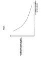
- FIG. 4 is a block diagram illustrating a relationship between a correlation value between the branches of the angle diversity and a distance of orientations (angular difference between beams).
- a vertical axis represents a correlation value ⁇ between the branches of the angle diversity and a horizontal axis represents an angular difference ⁇ between beams of the branches.
- the correlation value ⁇ between the branches of the angle diversity decreases as the angular difference between beams of the branches ⁇ increases.
- the orientation vectors (directionality) G1 and G2 of DR1a and DR1b shown in FIG. 3 are defined as follows.
- G ⁇ 1 g ⁇ 1 ⁇ exp j ⁇ ⁇ 1
- G ⁇ 2 g ⁇ 2 ⁇ exp j ⁇ ⁇ 2 in the above equations 3, 4
- g1 is an amplitude of an directional vector in the beam of DR1a
- ⁇ 1 is an angle of elevation of the directional vector
- g2 is an amplitude of an directional vector in the beam of DR1b
- ⁇ 2 is an angle of elevation of the directional vector.
- the vectors G1 and G2 are directional vectors which the branches show when outputs of the phased array synthesizing circuits 121 and 122 are maximized.
- the directionality G1 and the directionality G2 may come close one another according to circumstances. In this case, the correlation value between the branches increases and the diversity effect is decreased.
- the correlation value between the branches is calculated and the vector G1 is multiplied by exp(+j ⁇ /2) so that the correlation value decreases, i.e. the angular difference ⁇ is increased, on the basis of the relationship shown in shown in FIG. 4 .
- the vector G2 is multiplied by exp(-j ⁇ /2).
- perturbation correction on ⁇ is performed as follows.
- G ⁇ 1 g ⁇ 1 ⁇ exp j ⁇ ⁇ 1 ⁇ exp + j ⁇ / 2
- G ⁇ 2 g ⁇ 2 ⁇ exp j ⁇ ⁇ 2 ⁇ exp - j ⁇ / 2
- the angle diversity receiving device of the first exemplary embodiment can avoid decrease of the reception level even though a radio wave arriving angle changes, and can maintain the diversity effect even though a condition of tropospheric scatter propagation changes.
- angle diversity receiving device 100 illustrated in FIG. 1 can be configured also as follows.
- the angle diversity receiving device 100 is an angle diversity receiving device which performs angle diversity reception by configuring branches of the angle diversity using received signals of an array antenna. Then, the angle diversity receiving device 100 includes the array antenna, phased array synthesizing circuits 20-1 to 20-N, and the correlation control circuit 160.
- the phased array synthesizing circuits 201 to 20N perform phased array synthesis of received signals of a plurality of antenna elements included in the antenna array to generate received signals of the branches.
- the correlation control means outputs a correlation value between the received signals of the branches.
- the phased array synthesizing circuits 201 to 20N control an angular difference of orientations between the branches so that the correlation value outputted from the correlation control means 160 decreases.
- the angle diversity receiving device 100 can avoid decrease of the reception level even though the radio wave arriving angle changes, by performing phased array synthesis. Then, the angle diversity receiving device 100 can maintain the diversity effect even though a condition of tropospheric scatter propagation changes, by controlling an angular difference of orientations between the branches so that the correlation value between the branches decreases.
- FIG. 5 is a brief block diagram illustrating a configuration of an angle diversity receiving device 200 of a second exemplary embodiment of the invention.
- the angle diversity receiving device 200 differs from the first exemplary embodiment in that mutual correlation between outputs of a plurality of phased array synthesizing circuits is calculated by using a complex tap multiplication coefficient of an adaptive matched filter.
- the complex tap multiplication coefficients of the adaptive matched filters 131 to 13M are inputted into the correlation control circuit 160, and the correlation control circuit 160 calculates a correlation value on the basis of complex tap multiplication coefficients of two adaptive matched filters selected from the adaptive matched filters 131 to 13M.
- a configuration and basic operations of the angle diversity receiving device 200 except an inputting part for the correlation control circuit 160 are similar to the angle diversity receiving device 100 illustrated in FIG. 1 , and therefore detailed explanations thereof are omitted.
- FIG. 6 is a block diagram illustrating an example of a specific configuration of the angle diversity receiving device 200 illustrated in FIG. 5 .
- an angle diversity receiving device 200a includes, just like the angle diversity receiving device 100a, the array antenna 10, the phased array synthesizing circuits 121 and 122, the adaptive matched filters (AMF) 131 and 132, the diversity synthesizing circuit 140, the correlation control circuit (CORR) 160, and the automatic equalization circuit (decision feedback equalizer, DFE) 150.
- the array antenna 10 includes antenna elements 11a and 11b.
- the angle diversity receiving device 200a further includes, between the array antenna 10 and the phased array synthesizing circuits 121 and 122, the band pass filters (BPF) 221 and 222, the low noise amplifiers (LNA) 231 and 232, the received frequency converters (down converter, D/C) 241 and 242, and the automatic gain controllers (AGC) 251 and 252.
- BPF band pass filters
- LNA low noise amplifiers
- AGC automatic gain controllers
- the band pass filters 221 and 222, the low noise amplifiers 231 and 232, the received frequency converters 241 and 242, and the automatic gain controllers 251 and 252 have the same functions as those of the blocks with the same name shown in FIG. 7 .
- Each of the antenna elements 111 and 112 may be the horn antenna having the antenna reflector.
- the angle diversity receiving device 200a linearly synthesizes received signals of the antenna elements 111 and 112 with the phased array synthesizing circuits 121 and 122. Thereby control of a phased array is performed.
- mutual correlation between an output of the phased array synthesizing circuit 121 and an output of the phased array synthesizing circuit 122 is calculated by using the complex tap multiplication coefficients of the adaptive matched filters 131 and 132.
- correlation control circuit 160 calculates a correlation value between the complex tap multiplication coefficient of the adaptive matched filter 131 and the complex tap multiplication coefficient of the adaptive matched filter 132 and outputs the calculated correlation value to the phased array synthesizing circuits 121 and 122.
- a complex coefficient by which each sub-array is multiplied in the phased array synthesizing circuit 121 is represented as W1
- a complex coefficient by which each sub-array is multiplied in the second phased array synthesizing circuit 122 is represented as W2.
- the complex coefficient W1 is adaptively-adjusted on the basis of the output of the phased array synthesizing circuit 121 and the correlation value inputted from the correlation control circuit 160, so that the output of the phased array synthesizing circuit 121 is maximized.
- the complex coefficient W2 is adaptively-adjusted on the basis of the output of the phased array synthesizing circuit 122 and the correlation value inputted from the correlation control circuit 160, so that the output of the phased array synthesizing circuit 122 is maximized.
- Equation 1 and Equation 2 The values of W1 and W2 are calculated by Equation 1 and Equation 2, like the first exemplary embodiment.
- the orientation vectors (directionality) of angle diversity branches G1 and G2 are calculated by Equation (3) to Equation (6).
- the angle diversity receiving device of the second exemplary embodiment can avoid decrease of the reception level even though the radio wave arriving angle changes, and can maintain the diversity effect even though a condition of tropospheric scatter propagation changes, just like the angle diversity receiving device of the second exemplary embodiment.
- An angle diversity receiving device of a third exemplary embodiment of the invention includes a plurality of phased array synthesizing circuits for performing phased array synthesis of received signals of a plurality of antenna elements, as branches, by performing multiplication and addition of complex coefficients, a correlation control circuit for controlling an angular difference between orientations of branches so that a correlation value between the branches is minimized, on the basis of each output of the plurality of phased array synthesizing circuit, a plurality of adaptive matched filters to which outputs of the plurality of phased array synthesizing circuit are inputted, a diversity synthesizing circuit for performing angle diversity synthesis by synthesizing outputs of the plurality of adaptive matched filters, and an automatic equalization circuit for automatically equalizing an output of the diversity synthesizing circuit.
- An angle diversity receiving device of a fourth exemplary embodiment of the invention includes a plurality of phased array synthesizing circuits for performing phased array synthesis of received signals of a plurality of antenna elements, as branches, by performing multiplication and addition of complex coefficients, a plurality of adaptive matched filters to which outputs of the plurality of phased array synthesizing circuit are inputted, a diversity synthesizing circuit for performing angle diversity synthesis by synthesizing outputs of the plurality of adaptive matched filters, an automatic equalization circuit for automatically equalizing an output of the diversity synthesizing circuit, a correlation control circuit for controlling an angular difference between orientations of branches so that a correlation value between the branches is minimized on the basis of complex tap multiplication coefficients of the plurality of adaptive matched filters.
- the plurality of antenna elements of the third and the fourth exemplary embodiments of the invention may be horn antennas.
- the angle diversity receiving devices of the first to the fourth exemplary embodiments are applicable to communication employing angle diversity in propagation in which multi path fading occurs.
- the invention is applicable to tropospheric scatter propagation communication or land mobile communication.
Landscapes
- Engineering & Computer Science (AREA)
- Computer Networks & Wireless Communication (AREA)
- Signal Processing (AREA)
- Radio Transmission System (AREA)
- Variable-Direction Aerials And Aerial Arrays (AREA)
Abstract
a plurality of phased array synthesizing unit that generates a received signal of a branch by performing phased array synthesis for the received signals of a plurality of antenna elements included in the array antenna; and
a correlation control unit that outputs a correlation value for the received signals of two branches;
wherein the phased array synthesizing unit controls the angular difference in the orientations of the branches for which the correlation value was computed so that the correlation value decreases.
Description
- The invention relates to an angle diversity receiving device and an angle diversity receiving method.
-
FIG. 7 is a block diagram illustrating a configuration of an angle diversity receivingdevice 600 related to the invention. Referring toFIG. 7 , the angle diversity receivingdevice 600 includes a group ofantennas 611 composed of twohorn antennas device 600 receives a received signal from thehorn antenna 61A through a band pass filter (BPF) 221, a low noise amplifier (LNA) 231, a received frequency converter (down converter, D/C) 241, an automatic gain controller (AGC) 251, and an adaptive matched filter (AMF) 131. - Further, the angle diversity receiving
device 600 receives a received signal from thehorn antenna 61B through aband pass filter 222, alow noise amplifier 232, a receivedfrequency converter 242, anautomatic gain controller 252, and an adaptive matchedfilter 132. In this way, the angle diversity receivingdevice 600 receives the received signals from thehorn antennas - The band pass filters (BPF) 221 and 222 allow only signals within a frequency band required for reception to pass. The low noise amplifiers (LNA) 231 and 232 amplify the received signals. The received frequency converters (down converter, D/C) 241 and 242 frequency-convert the received signals. The automatic gain controllers (AGC) 251 and 252 amplify the received signals so as to suppress amplitude change of the received signals outputted to following steps. The adaptive matched
filters - Incidentally,
diversity synthesizing circuit 140 performs diversity combining of signals inputted from the adaptive matchedfilters - Such kinds of angle diversity receiving devices are disclosed for example in PTLs (Patent Literatures) 1 to 6 and NPL (Non Patent Literature) 1, except than above described one.
-
FIG. 8 is a diagram explaining tropospheric scatter propagation. Areceiving antenna 812 corresponds to, for example, the group ofantennas 611 of the angle diversity receivingdevice 600 shown inFIG. 7 . A radio wave transmitted from a transmitting station 811 is scattered at a first scattering point STa and a second scattering point STb, and received, as signals of orientations DTa and DTb, by the group ofantennas 812. -
FIG. 9 is a diagram explaining operations of the angle diversity receivingdevice 600 based on a related technology. The angle diversity receivingdevice 600 shown inFIG. 7 andFIG. 9 operates as follows. As shown inFIG. 9 , two beams of antenna DR6a and DR6b are fixed at predetermined angles. Then, the group ofantennas 611 performs angle diversity processing on received signals arriving from the dual beams of DR6a and DR6b. - The angle diversity receiving
device 600 receives an arriving radio wave in a transmitting direction DTa ofFIG. 8 based on the beam of DR6a inFIG. 9 , and receives an arriving radio wave in a transmitting direction DTb ofFIG. 8 based on the beam of DR6b. Here, if a condition of tropospheric scatter changes and a spatial position of the scattering points STa or STb changes, the transmitting direction DTa or the transmitting direction DTb changes. As a result, intensity of the received signals in the angle diversity receivingdevice 600 may remarkably decrease. - That is, in the angle diversity system in which a direction of the horn antenna is fixed, when an azimuth of an arriving radio wave changes as a result of propagation condition changes, a reception level may be reduced. Particularly, in tropospheric scatter propagation, a condition of scatter propagation in troposphere widely changes due to climate change. Consequently, in the angle diversity system in which the orientations of the antennas are fixed, long-period fading with propagation loss of 10 dB to 20-odd dB occurs throughout one year, and a reception level of the radio wave may decrease.
- Additionally, in the angle diversity receiving device, an angle between a plurality of receiving horns is preliminarily arranged so that a correlation value between branches does not increase. In the angle diversity receiving device, a correlation value between the branches may increase as a condition of troposphere scatter changes and a diversity effect may decrease.
-
- [PTL 1] Japanese Patent Publication No.
2982504 - [PTL 2] United States Patent
US 7,623,084 B2 - [PTL 3] Japanese unexamined patent publication No.
06-029890 - [PTL 4] Japanese unexamined patent publication No.
05-344029 - [PTL 5] Japanese unexamined patent publication No.
04-227132 - [PTL 6] Japanese examined patent publication No.
07-050868 - [NPL 1]'Performance of an Experimental Angle-Diversity Troposcatter System'(P. Monsen, IEEE TRANSACTIONS ON COMMUNICATIONS, APRIL 1972, P242-247)
- As described above, the angle diversity receiving device is required to be able to avoid decrease of the reception level even though an arriving angle of a radio wave changes, and to maintain the diversity effect even though a condition of tropospheric scatter propagation changes.
- An object of the invention is to provide an angle diversity receiving device and an angle diversity receiving method which can avoid decrease of the reception level even though an arriving angle of a radio wave changes, and to maintain the diversity effect even though a condition of tropospheric scatter propagation changes.
- The angle diversity receiving device of the invention is an angle diversity receiving device which performs angle diversity reception by configuring branches of an angle diversity in accordance with received signals of an array antenna and the angle diversity receiving device includes a plurality of phased array synthesizing means for generating a received signal of the branch by performing phased array synthesis for the received signals of a plurality of antenna elements included in the array antenna and correlation control means for outputting a correlation value between two received signals of the branches, and the phased array synthesizing means controls an angular difference in orientations of the branches for which the correlation value is calculated so that the correlation value decreases.
- The angle diversity receiving method of the invention is an angle diversity receiving method in which angle diversity reception is performed by configuring branches of diversity in accordance with received signals of an array antenna, and the method includes generating a received signal of a branch by performing phased array synthesis for the received signals of a plurality of antenna elements included in the array antenna, outputting a correlation value for two received signals of the branches and controlling an angular difference in orientations between the branches for which the correlation value is calculated so that the correlation value decreases.
- The angle diversity receiving device and the angle diversity receiving method of the invention can avoid decrease of a reception level even though an arriving angle of a radio wave changes, and can maintain a diversity effect even though a condition of tropospheric scatter propagation changes.
-
- [
FIG. 1] FIG. 1 is a brief block diagram illustrating a configuration of an angle diversity receiving device of a first exemplary embodiment of the invention. - [
FIG. 2] FIG. 2 is a brief block diagram illustrating a form of a specific configuration of the angle diversity receiving device illustrated inFIG. 1 . - [
FIG. 3] FIG. 3 is a block diagram explaining an operation of the angle diversity receiving device. - [
FIG. 4] FIG.4 is a block diagram illustrating a relationship between a correlation value between branches of the angle diversity and distance of orientations (angular difference between beams). - [
FIG. 5] FIG. 5 is a brief block diagram illustrating a configuration of an angle diversity receiving device of a second exemplary embodiment of the invention. - [
FIG. 6] FIG. 6 is a block diagram illustrating an example of a specific configuration of the angle diversity receiving device illustrated inFIG. 5 . - [
FIG. 7] FIG. 7 is a block diagram illustrating a configuration of an angle diversity receiving device related to the invention. - [
FIG. 8] FIG. 8 is a block diagram explaining tropospheric scatter propagation. - [
FIG. 9] FIG. 9 is a block diagram explaining an operation of the angle diversity receiving device of a related technology. -
FIG. 1 is a brief block diagram illustrating a configuration of an angle diversity receiving device 100 of a first exemplary embodiment of the invention. InFIG. 1 , the angle diversity receiving device 100 of the first exemplary embodiment includes anarray antenna 10, M phasedarray synthesizing circuits 121 to 12M, M adaptive matchedfilters 131 to 13M, a diversity synthesizingcircuit 140, anautomatic equalization circuit 150, and acorrelation control circuit 160. Thearray antenna 10 includesN antenna elements 111 to 11N. Here, each of M and N is an integer which is two or more than two, and M is equal to N or less than N. - Received signals from the
antenna elements 111 to 11N are inputted to the phasedarray synthesizing circuits 121 to 12M. Each of the phasedarray synthesizing circuits 121 to 12M selects two or more than two received signals from the received signals received from theantenna elements 111 to 11N and performs phased array synthesis. The phasedarray synthesizing circuits 121 to 12M form M branches. Then, outputs of the phasedarray synthesizing circuits 121 to 12M are inputted into M adaptive matchedfilters 131 to 13M, respectively, and synthesized bydiversity synthesizing circuit 140. In this way, the angle diversity synthesis is performed to M branches. An output of thediversity synthesizing circuit 140 is automatically equalized by theautomatic equalization circuit 150 and consequently a received data signal is acquired. - The angle diversity receiving device 100 controls orientations of the branches as an arrive direction of a radio wave changes, by using the phased
array synthesizing circuits 121 to 12M connecting to the plurality of antenna elements. The angle diversity receiving device 100 forms a plurality of subarrays from among the plurality of branches, and utilizes outputs of the subarrays as the received signals of the branches of the angle diversity. The angle diversity receiving device 100 performs adaptive matched filtering between the branches of the angle diversity, performs maximal ratio synthesizing including time-dispersed multi paths, and performs optimal angle diversity reception. - In the first exemplary embodiment, the
correlation control circuit 160 calculates a correlation value between two outputs selected from outputs of the phasedarray synthesizing circuits 121 to 12M. The calculated correlation value is inputted into the phased array synthesizing circuit which outputs the two selected signals. Thecorrelation control circuit 160 may sequentially calculate a correlation value between two outputs in M outputs of the phasedarray synthesizing circuits 121 to 12M. -
FIG. 2 is a block diagram illustrating a form of a specific configuration of the angle diversity receiving device 100 illustrated inFIG. 1 . - An angle
diversity receiving device 100a includes thearray antenna 10, the phasedarray synthesizing circuits diversity synthesizing circuit 140, the correlation control circuit (CORR) 160, and the automatic equalization circuit (decision feedback equalizer, DFE) 150. Thearray antenna 10 includes antenna elements 11a and 11b. - Further, the angle
diversity receiving device 100a includes, between thearray antenna 10 and the phasedarray synthesizing circuits - Functions of the band pass filters 221 and 222, the
low noise amplifiers frequency converters automatic gain controllers FIG. 7 . - In
FIG. 2 , the number of the diversity branches is two. Further, thearray antenna 10 includes theantenna elements antenna elements - The angle
diversity receiving device 100a performs linear synthesis of received signals received by theantenna elements array synthesizing circuits diversity receiving device 100a controls the phased array. - The
correlation control circuit 160 calculates correlation between an output signal of the phasedarray synthesizing circuit 121 and an output signal of the phasedarray synthesizing circuit 122 and outputs the calculated correlation to the phasedarray synthesizing circuits - Here, a complex coefficient by which each sub-array is multiplied in the phased
array synthesizing circuit 121 is represented as W1, and a complex coefficient by which each sub-array is multiplied in the phasedarray synthesizing circuit 122 is represented as W2. - W1 is multiplied by a signal of each sub-array in a
complex multiplier 19a or acomplex multiplier 19b. Outputs of thecomplex multipliers adder 19c and the sum of the outputs of thecomplex multipliers array synthesizing circuit 121. W2 is multiplied by a signal of each sub-array in acomplex multiplier 20a or acomplex multiplier 20b. Outputs of thecomplex multipliers adder 20c and the sum of the outputs of thecomplex multipliers array synthesizing circuit 122. - The complex coefficient W1 is adjusted on the basis of the output of the phased
array synthesizing circuit 121 and the correlation value inputted from thecorrelation control circuit 160 so that the output of the phasedarray synthesizing circuit 121 is maximized. - Further, the complex coefficient W2 is adjusted on the basis of the output of the phased
array synthesizing circuit 122 and the correlation value inputted from thecorrelation control circuit 160 so that the output of the phasedarray synthesizing circuit 122 is maximized. - Specifically, weighting coefficients W1 and W2 are calculated in accordance with following adaptive algorithm.


where r1 and r2 are input signal vectors of the phasedarray synthesizing circuits FIG. 2 ), y1 and y2 are output signal vectors of the phasedarray synthesizing circuits Equation 1 and Equation 2, since the algorithm is positive feedback type, (1 - µ) is multiplied in order to avoid divergence of the calculation result and sequentially multiply by a multiplier for adaptively converging. - According to the algorithm described above, the phased
array synthesizing circuits FIG. 3 . DR1a is a beam of an antenna of a first diversity branch of the phasedarray synthesizing circuit 121. DR1b is a beam of the antenna of a second diversity branch of the phasedarray synthesizing circuit 122. An angle of each orientation is variable. - A case is explained, in which the angle
diversity receiving devices 100 and 100a of the first exemplary embodiment are applied to tropospheric scatter propagation. - Tropospheric scatter propagation is explained again by using
FIG. 8 . An array antenna of a receiving station (anglediversity receiving devices 100 and 100a) corresponds to the receivingantenna 812. A transmission beam transmitted from the transmitting station 811 is scattered in the troposphere. The scattering region is called a scattering volume and includes spatial extent. A signal from the first scattering point STa in the orientation DTa and a signal from the second scattering point STb in the orientation DTb arrive at the receivingantenna 812 of the over-the-horizon receiving station (anglediversity receiving devices 100 and 100a). - Here, the scattering points STa and STb are spatially separated and each scattering phenomenon randomly changes. The scattering phenomena at the scattering points STa and STb are therefore uncorrelated one another. A received signals between the orientations DTa and DTb are an uncorrelated fading signal one another.
- Therefore, if a plurality of receiving elements having an angular difference therebetween (e.g. DR1a, DR1b in
FIG. 3 ) receive a signal in the orientation DTa and a signal in the orientation DTb, it is possible to synthesize branches of diversity which are uncorrelated one another and to perform angle diversity. - Incidentally, in actual scatter propagation, when the scattering points STa and STb are spatially closed to each other, signals from the scattering points are not perfectly uncorrelated and include some degree of correlation. Patent Literature 2 describes if a correlation value between branches of angle diversity is equal to or less than 0.6, the angle diversity is effective.
- If spatial distance between the scattering points STa and STb increases, the correlation value decreases and an angle between the orientations DTa and DTb increases. In the invention, the beams of DR1a and DR1b which increase an angle between the branches of the angle diversity are arranged by controlling an orientation of the phased array, and the correlation value is decreased to maintain the diversity effect.
-
FIG. 4 is a block diagram illustrating a relationship between a correlation value between the branches of the angle diversity and a distance of orientations (angular difference between beams). InFIG. 4 , a vertical axis represents a correlation value η between the branches of the angle diversity and a horizontal axis represents an angular difference Δθ between beams of the branches. As shown inFIG. 4 , the correlation value η between the branches of the angle diversity decreases as the angular difference between beams of the branches Δθ increases. - The orientation vectors (directionality) G1 and G2 of DR1a and DR1b shown in
FIG. 3 are defined as follows.

in the above equations 3, 4, g1 is an amplitude of an directional vector in the beam of DR1a, θ1 is an angle of elevation of the directional vector, g2 is an amplitude of an directional vector in the beam of DR1b, and θ2 is an angle of elevation of the directional vector. - The vectors G1 and G2 are directional vectors which the branches show when outputs of the phased
array synthesizing circuits FIG. 8 come close to each other, the directionality G1 and the directionality G2 may come close one another according to circumstances. In this case, the correlation value between the branches increases and the diversity effect is decreased. In the invention, the correlation value between the branches is calculated and the vector G1 is multiplied by exp(+jΔθ/2) so that the correlation value decreases, i.e. the angular difference Δθ is increased, on the basis of the relationship shown in shown inFIG. 4 . The vector G2 is multiplied by exp(-jΔθ/2). With respect to G1 and G2, perturbation correction on Δθ is performed as follows.

- As the result, the angle diversity receiving device of the first exemplary embodiment can avoid decrease of the reception level even though a radio wave arriving angle changes, and can maintain the diversity effect even though a condition of tropospheric scatter propagation changes.
- Additionally, the angle diversity receiving device 100 illustrated in
FIG. 1 can be configured also as follows. - The angle diversity receiving device 100 is an angle diversity receiving device which performs angle diversity reception by configuring branches of the angle diversity using received signals of an array antenna. Then, the angle diversity receiving device 100 includes the array antenna, phased array synthesizing circuits 20-1 to 20-N, and the
correlation control circuit 160. - The phased array synthesizing circuits 201 to 20N perform phased array synthesis of received signals of a plurality of antenna elements included in the antenna array to generate received signals of the branches. The correlation control means outputs a correlation value between the received signals of the branches. The phased array synthesizing circuits 201 to 20N control an angular difference of orientations between the branches so that the correlation value outputted from the correlation control means 160 decreases.
- In such configuration, the angle diversity receiving device 100 can avoid decrease of the reception level even though the radio wave arriving angle changes, by performing phased array synthesis. Then, the angle diversity receiving device 100 can maintain the diversity effect even though a condition of tropospheric scatter propagation changes, by controlling an angular difference of orientations between the branches so that the correlation value between the branches decreases.
-
FIG. 5 is a brief block diagram illustrating a configuration of an anglediversity receiving device 200 of a second exemplary embodiment of the invention. The anglediversity receiving device 200 differs from the first exemplary embodiment in that mutual correlation between outputs of a plurality of phased array synthesizing circuits is calculated by using a complex tap multiplication coefficient of an adaptive matched filter. - Namely, referring to
FIG. 5 , the complex tap multiplication coefficients of the adaptive matchedfilters 131 to 13M are inputted into thecorrelation control circuit 160, and thecorrelation control circuit 160 calculates a correlation value on the basis of complex tap multiplication coefficients of two adaptive matched filters selected from the adaptive matchedfilters 131 to 13M. Incidentally, a configuration and basic operations of the anglediversity receiving device 200 except an inputting part for thecorrelation control circuit 160 are similar to the angle diversity receiving device 100 illustrated inFIG. 1 , and therefore detailed explanations thereof are omitted. -
FIG. 6 is a block diagram illustrating an example of a specific configuration of the anglediversity receiving device 200 illustrated inFIG. 5 . Referring toFIG. 6 , an anglediversity receiving device 200a includes, just like the anglediversity receiving device 100a, thearray antenna 10, the phasedarray synthesizing circuits diversity synthesizing circuit 140, the correlation control circuit (CORR) 160, and the automatic equalization circuit (decision feedback equalizer, DFE) 150. Thearray antenna 10 includes antenna elements 11a and 11b. - The angle
diversity receiving device 200a further includes, between thearray antenna 10 and the phasedarray synthesizing circuits - The band pass filters 221 and 222, the
low noise amplifiers frequency converters automatic gain controllers FIG. 7 . - That is, the number of diversity branches of the angle
diversity receiving device 200a shown inFIG. 6 is two. Each of theantenna elements - The angle
diversity receiving device 200a linearly synthesizes received signals of theantenna elements array synthesizing circuits - In the angle
diversity receiving device 200a, mutual correlation between an output of the phasedarray synthesizing circuit 121 and an output of the phasedarray synthesizing circuit 122 is calculated by using the complex tap multiplication coefficients of the adaptive matchedfilters - That is,
correlation control circuit 160 calculates a correlation value between the complex tap multiplication coefficient of the adaptive matchedfilter 131 and the complex tap multiplication coefficient of the adaptive matchedfilter 132 and outputs the calculated correlation value to the phasedarray synthesizing circuits - Here, a complex coefficient by which each sub-array is multiplied in the phased
array synthesizing circuit 121 is represented as W1, and a complex coefficient by which each sub-array is multiplied in the second phasedarray synthesizing circuit 122 is represented as W2. - The complex coefficient W1 is adaptively-adjusted on the basis of the output of the phased
array synthesizing circuit 121 and the correlation value inputted from thecorrelation control circuit 160, so that the output of the phasedarray synthesizing circuit 121 is maximized. - The complex coefficient W2 is adaptively-adjusted on the basis of the output of the phased
array synthesizing circuit 122 and the correlation value inputted from thecorrelation control circuit 160, so that the output of the phasedarray synthesizing circuit 122 is maximized. - The values of W1 and W2 are calculated by
Equation 1 and Equation 2, like the first exemplary embodiment. The orientation vectors (directionality) of angle diversity branches G1 and G2 are calculated by Equation (3) to Equation (6). - In this configuration, when outputs of the phased
array synthesizing circuits - Consequently, the angle diversity receiving device of the second exemplary embodiment can avoid decrease of the reception level even though the radio wave arriving angle changes, and can maintain the diversity effect even though a condition of tropospheric scatter propagation changes, just like the angle diversity receiving device of the second exemplary embodiment.
- An angle diversity receiving device of a third exemplary embodiment of the invention includes a plurality of phased array synthesizing circuits for performing phased array synthesis of received signals of a plurality of antenna elements, as branches, by performing multiplication and addition of complex coefficients, a correlation control circuit for controlling an angular difference between orientations of branches so that a correlation value between the branches is minimized, on the basis of each output of the plurality of phased array synthesizing circuit, a plurality of adaptive matched filters to which outputs of the plurality of phased array synthesizing circuit are inputted, a diversity synthesizing circuit for performing angle diversity synthesis by synthesizing outputs of the plurality of adaptive matched filters, and an automatic equalization circuit for automatically equalizing an output of the diversity synthesizing circuit.
- An angle diversity receiving device of a fourth exemplary embodiment of the invention includes a plurality of phased array synthesizing circuits for performing phased array synthesis of received signals of a plurality of antenna elements, as branches, by performing multiplication and addition of complex coefficients, a plurality of adaptive matched filters to which outputs of the plurality of phased array synthesizing circuit are inputted, a diversity synthesizing circuit for performing angle diversity synthesis by synthesizing outputs of the plurality of adaptive matched filters, an automatic equalization circuit for automatically equalizing an output of the diversity synthesizing circuit, a correlation control circuit for controlling an angular difference between orientations of branches so that a correlation value between the branches is minimized on the basis of complex tap multiplication coefficients of the plurality of adaptive matched filters.
- The plurality of antenna elements of the third and the fourth exemplary embodiments of the invention may be horn antennas.
- Needless to say, the invention of the present application is not limited to the above mentioned embodiments and it is to be understood that to the configurations and details of the invention of the present application, various changes can be made within the scope of the invention of the present application.
- This application claims priority from Japanese Patent Application No.
2012-076489 filed on March 29, 2012 - For example, the angle diversity receiving devices of the first to the fourth exemplary embodiments are applicable to communication employing angle diversity in propagation in which multi path fading occurs. As usage examples, the invention is applicable to tropospheric scatter propagation communication or land mobile communication.
-
- 10, 611
- array antenna
- 111-11N, 61 A, 61B
- antenna element
- 100, 100a, 200, 200a
- angle diversity receiving device
- 121-12M
- phased array synthesizing circuit
- 131-13M
- adaptive matched filter
- 140
- diversity synthesizing circuit
- 150
- automatic equalization circuit
- 160
- correlation control circuit
- 19a, 19b, 20a, 20b
- complex multiplier
- 19c, 20c
- adder
- 160
- correlation control circuit (CORR)
- 221, 222
- band path filter (BPF)
- 231, 232
- low noise amplifier (LNA)
- 241, 242
- reception frequency converter (down converter, D/C)
- 251, 252
- automatic gain controller (AGC)
- 811
- transmitting station
- 812
- receiving antenna
Claims (5)
- An angle diversity receiving device performing angle diversity reception by configuring branches of angle diversity in accordance with received signals of an array antenna, the angle diversity receiving device comprising:a plurality of phased array synthesizing means for generating a received signal of the branch by performing phased array synthesis for received signals of a plurality of antenna elements included in the array antenna; andcorrelation control means for calculating and outputting a correlation value between two received signals of the branches,
whereinthe phased array synthesizing means controls an angular difference in orientations of the branches for which the correlation value is calculated so that the correlation value decreases. - The angle diversity receiving device of claim 1, further comprising:a plurality of adaptive matched filters for receiving outputs of the phased array synthesizing means;diversity synthesizing means for performing angle diversity synthesis by synthesizing outputs of the adaptive matched filters; andautomatic equalizing means for automatically equalizing an output of the diversity synthesizing means,wherein the correlation control means outputs the correlation value on the basis of two outputs of the phased array synthesizing means, and the phased array synthesizing means performs phased array synthesis by multiplying the received signal of the branch by a complex coefficient based on the correlation value and adding up the results of the multiplication.
- The angle diversity receiving device of claim 1, further comprising:a plurality of adaptive matched filters for receiving outputs of the phased array synthesizing means;diversity synthesizing means for performing angle diversity synthesis by synthesizing outputs of the adaptive matched filters; andautomatic equalizing means for automatically equalizing an output of the diversity synthesizing means,wherein the correlation control circuit outputs the correlation value on the basis of two complex tap multiplication coefficients of the adaptive matched filters, and each of the phased array synthesizing means performs phased array synthesis by multiplying the received signal of the branch by a complex coefficient based on the correlation value and adds up the results of the multiplication.
- The angle diversity receiving device according to any one of claim 1 to claim 3, wherein the plurality of antenna elements are horn antennas.
- An angle diversity receiving method performing angle diversity reception by configuring branches of diversity in accordance with received signals of an array antenna, comprising:generating a received signal of a branch by performing phased array synthesis for the received signals of a plurality of antenna elements included in the array antenna;outputting a correlation value between two received signals of the branches; andcontrolling an angular difference in orientations of the branches for which the correlation value is calculated so that the correlation value decreases.
Applications Claiming Priority (2)
| Application Number | Priority Date | Filing Date | Title |
|---|---|---|---|
| JP2012076489 | 2012-03-29 | ||
| PCT/JP2013/001941 WO2013145663A1 (en) | 2012-03-29 | 2013-03-22 | Angle diversity receiving device and angle diversity receiving method |
Publications (2)
| Publication Number | Publication Date |
|---|---|
| EP2833560A1 true EP2833560A1 (en) | 2015-02-04 |
| EP2833560A4 EP2833560A4 (en) | 2015-12-16 |
Family
ID=49258972
Family Applications (1)
| Application Number | Title | Priority Date | Filing Date |
|---|---|---|---|
| EP13768203.5A Withdrawn EP2833560A4 (en) | 2012-03-29 | 2013-03-22 | Angle diversity receiving device and angle diversity receiving method |
Country Status (4)
| Country | Link |
|---|---|
| US (1) | US9407301B2 (en) |
| EP (1) | EP2833560A4 (en) |
| JP (1) | JP5871059B2 (en) |
| WO (1) | WO2013145663A1 (en) |
Cited By (1)
| Publication number | Priority date | Publication date | Assignee | Title |
|---|---|---|---|---|
| EP3618304A4 (en) * | 2017-04-27 | 2020-04-22 | Nec Corporation | RADIO COMMUNICATION DEVICE, RADIO RECEPTION DEVICE, AND RADIO COMMUNICATION SYSTEM |
Families Citing this family (5)
| Publication number | Priority date | Publication date | Assignee | Title |
|---|---|---|---|---|
| EP3046277B1 (en) * | 2015-01-19 | 2023-09-13 | Harman Becker Automotive Systems GmbH | Method and system for reception improvement of an FM tuner in a common channel interference situation |
| WO2016132591A1 (en) * | 2015-02-17 | 2016-08-25 | 三菱電機株式会社 | Receiver device and receiving method |
| JP6679830B2 (en) * | 2015-03-11 | 2020-04-15 | 日本電気株式会社 | Receiving device and receiving method |
| CN110571512B (en) * | 2019-09-02 | 2021-01-12 | 中国电子科技集团公司第五十四研究所 | A Plane Angle Diversity Antenna for Over-the-horizon Wireless Communication |
| US20240426959A1 (en) * | 2021-08-30 | 2024-12-26 | Nec Corporation | Antenna direction calculation device, processing method, and recording medium |
Family Cites Families (15)
| Publication number | Priority date | Publication date | Assignee | Title |
|---|---|---|---|---|
| JPH0750868B2 (en) | 1989-03-03 | 1995-05-31 | 日本電気株式会社 | Angle diversity receiver |
| EP0480157A1 (en) | 1990-09-07 | 1992-04-15 | Alcatel N.V. | Angle diversity antenna with phased array feed |
| JP2765377B2 (en) | 1992-07-08 | 1998-06-11 | 日本電気株式会社 | Interference wave canceller |
| US5379046A (en) | 1992-06-09 | 1995-01-03 | Nec Corporation | Interference wave canceller |
| JP2894088B2 (en) | 1992-06-09 | 1999-05-24 | 日本電気株式会社 | Interference wave canceller |
| JP2982504B2 (en) | 1992-07-31 | 1999-11-22 | 日本電気株式会社 | Adaptive receiver |
| JP2909356B2 (en) | 1993-08-06 | 1999-06-23 | 株式会社東芝 | Cordless phone system |
| JP2561031B2 (en) | 1994-06-07 | 1996-12-04 | 日本電気株式会社 | Transceiver |
| US5929811A (en) * | 1995-03-28 | 1999-07-27 | Rilling; Kenneth F. | Adaptive array with automatic loop gain control |
| US5608409A (en) * | 1995-03-28 | 1997-03-04 | Rilling; Kenneth F. | Adaptive array with automatic loop gain control |
| JP2980053B2 (en) * | 1997-03-28 | 1999-11-22 | 日本電気株式会社 | Interference wave canceller |
| JP2003338804A (en) | 2002-05-22 | 2003-11-28 | Nec Corp | Path search apparatus and method, and antenna array receiving apparatus using the same |
| JP4536733B2 (en) * | 2004-12-28 | 2010-09-01 | 富士通株式会社 | Wireless communication system |
| EP1843485B1 (en) | 2006-03-30 | 2016-06-08 | Sony Deutschland Gmbh | Multiple-input multiple-output (MIMO) spatial multiplexing system with dynamic antenna beam combination selection capability |
| US7623084B2 (en) | 2006-09-12 | 2009-11-24 | General Dynamics C4 Systems, Inc. | Angular diversity antenna system and feed assembly for same |
-
2013
- 2013-03-22 EP EP13768203.5A patent/EP2833560A4/en not_active Withdrawn
- 2013-03-22 US US14/389,094 patent/US9407301B2/en active Active
- 2013-03-22 JP JP2014507410A patent/JP5871059B2/en not_active Expired - Fee Related
- 2013-03-22 WO PCT/JP2013/001941 patent/WO2013145663A1/en not_active Ceased
Cited By (1)
| Publication number | Priority date | Publication date | Assignee | Title |
|---|---|---|---|---|
| EP3618304A4 (en) * | 2017-04-27 | 2020-04-22 | Nec Corporation | RADIO COMMUNICATION DEVICE, RADIO RECEPTION DEVICE, AND RADIO COMMUNICATION SYSTEM |
Also Published As
| Publication number | Publication date |
|---|---|
| JP5871059B2 (en) | 2016-03-01 |
| EP2833560A4 (en) | 2015-12-16 |
| WO2013145663A1 (en) | 2013-10-03 |
| US9407301B2 (en) | 2016-08-02 |
| JPWO2013145663A1 (en) | 2015-12-10 |
| US20150072634A1 (en) | 2015-03-12 |
Similar Documents
| Publication | Publication Date | Title |
|---|---|---|
| US9407301B2 (en) | Angle diversity receiving device and angle diversity receiving method | |
| JP3888189B2 (en) | Adaptive antenna base station equipment | |
| US8228878B2 (en) | Method and system of communications | |
| JP5073809B2 (en) | Channel information prediction system and channel information prediction method | |
| JP4481336B2 (en) | Channel information prediction system and channel information prediction method | |
| US20120020396A1 (en) | Calibration of smart antenna systems | |
| JPH07336129A (en) | Transceiver | |
| KR101292814B1 (en) | Method for Maximal Ratio Combining of Spatially Filtered Signals and Apparatus therefor | |
| EP1830487A2 (en) | Multiple input multiple output communication apparatus | |
| US20110151908A1 (en) | Mobile communication system, base station and interference cancellation method | |
| US10008773B2 (en) | Wireless communication apparatus, antenna directionality control method, and power supply circuit | |
| US20070249308A1 (en) | Method and apparatus for uplink coverage improvement | |
| CN111478723A (en) | Method and device for adaptively calculating forming factor | |
| KR101748814B1 (en) | Apparatus and method for signal trransmitting and receiviing with hibrid beamforming | |
| JP2016171362A (en) | Receiving apparatus and receiving method | |
| KR102261004B1 (en) | Full-duplex decode-and-forward relay to increase energy harvesting | |
| US20110098067A1 (en) | Mobile communication system, base station and interference removal method | |
| Alias Jeyanthi et al. | A simple adaptive beamforming algorithm with interference suppression | |
| Shaikh et al. | Linear, non-linear adaptive beamforming algorithm for smart antenna system | |
| JP5830397B2 (en) | Array antenna | |
| US20140266906A1 (en) | Angle diversity receiving apparatus | |
| JP4570900B2 (en) | Receiver, transmitter, radio communication system, and reception method | |
| Fedosov et al. | Investigation of the Influence of Spatial Correlation on the Performance of the MIMO System When Using the Adaptation Algorithm | |
| Gouri Nayana et al. | An overview on beamforming and its issues for 60 GHz wireless communications | |
| JP4778982B2 (en) | Reception apparatus and interference suppression method |
Legal Events
| Date | Code | Title | Description |
|---|---|---|---|
| PUAI | Public reference made under article 153(3) epc to a published international application that has entered the european phase |
Free format text: ORIGINAL CODE: 0009012 |
|
| 17P | Request for examination filed |
Effective date: 20141008 |
|
| AK | Designated contracting states |
Kind code of ref document: A1 Designated state(s): AL AT BE BG CH CY CZ DE DK EE ES FI FR GB GR HR HU IE IS IT LI LT LU LV MC MK MT NL NO PL PT RO RS SE SI SK SM TR |
|
| AX | Request for extension of the european patent |
Extension state: BA ME |
|
| DAX | Request for extension of the european patent (deleted) | ||
| RA4 | Supplementary search report drawn up and despatched (corrected) |
Effective date: 20151117 |
|
| RIC1 | Information provided on ipc code assigned before grant |
Ipc: H01Q 3/26 20060101ALI20151111BHEP Ipc: H01Q 25/00 20060101ALI20151111BHEP Ipc: H04B 7/10 20060101AFI20151111BHEP Ipc: H04B 7/08 20060101ALI20151111BHEP |
|
| STAA | Information on the status of an ep patent application or granted ep patent |
Free format text: STATUS: THE APPLICATION IS DEEMED TO BE WITHDRAWN |
|
| 18D | Application deemed to be withdrawn |
Effective date: 20160615 |