EP2833523A1 - Stator of resolver and method for manufacturing stator structure - Google Patents
Stator of resolver and method for manufacturing stator structure Download PDFInfo
- Publication number
- EP2833523A1 EP2833523A1 EP13767867.8A EP13767867A EP2833523A1 EP 2833523 A1 EP2833523 A1 EP 2833523A1 EP 13767867 A EP13767867 A EP 13767867A EP 2833523 A1 EP2833523 A1 EP 2833523A1
- Authority
- EP
- European Patent Office
- Prior art keywords
- stator
- external cable
- connecting portion
- stator winding
- cable connecting
- Prior art date
- Legal status (The legal status is an assumption and is not a legal conclusion. Google has not performed a legal analysis and makes no representation as to the accuracy of the status listed.)
- Granted
Links
Images







Classifications
-
- G—PHYSICS
- G01—MEASURING; TESTING
- G01B—MEASURING LENGTH, THICKNESS OR SIMILAR LINEAR DIMENSIONS; MEASURING ANGLES; MEASURING AREAS; MEASURING IRREGULARITIES OF SURFACES OR CONTOURS
- G01B7/00—Measuring arrangements characterised by the use of electric or magnetic techniques
- G01B7/30—Measuring arrangements characterised by the use of electric or magnetic techniques for measuring angles or tapers; for testing the alignment of axes
-
- H—ELECTRICITY
- H02—GENERATION; CONVERSION OR DISTRIBUTION OF ELECTRIC POWER
- H02K—DYNAMO-ELECTRIC MACHINES
- H02K24/00—Machines adapted for the instantaneous transmission or reception of the angular displacement of rotating parts, e.g. synchro, selsyn
-
- H—ELECTRICITY
- H02—GENERATION; CONVERSION OR DISTRIBUTION OF ELECTRIC POWER
- H02K—DYNAMO-ELECTRIC MACHINES
- H02K3/00—Details of windings
- H02K3/46—Fastening of windings on the stator or rotor structure
- H02K3/52—Fastening salient pole windings or connections thereto
- H02K3/521—Fastening salient pole windings or connections thereto applicable to stators only
- H02K3/522—Fastening salient pole windings or connections thereto applicable to stators only for generally annular cores with salient poles
-
- H—ELECTRICITY
- H01—ELECTRIC ELEMENTS
- H01R—ELECTRICALLY-CONDUCTIVE CONNECTIONS; STRUCTURAL ASSOCIATIONS OF A PLURALITY OF MUTUALLY-INSULATED ELECTRICAL CONNECTING ELEMENTS; COUPLING DEVICES; CURRENT COLLECTORS
- H01R39/00—Rotary current collectors, distributors or interrupters
- H01R39/02—Details for dynamo electric machines
- H01R39/32—Connections of conductor to commutator segment
-
- H—ELECTRICITY
- H02—GENERATION; CONVERSION OR DISTRIBUTION OF ELECTRIC POWER
- H02K—DYNAMO-ELECTRIC MACHINES
- H02K5/00—Casings; Enclosures; Supports
- H02K5/04—Casings or enclosures characterised by the shape, form or construction thereof
- H02K5/22—Auxiliary parts of casings not covered by groups H02K5/06-H02K5/20, e.g. shaped to form connection boxes or terminal boxes
- H02K5/225—Terminal boxes or connection arrangements
-
- Y—GENERAL TAGGING OF NEW TECHNOLOGICAL DEVELOPMENTS; GENERAL TAGGING OF CROSS-SECTIONAL TECHNOLOGIES SPANNING OVER SEVERAL SECTIONS OF THE IPC; TECHNICAL SUBJECTS COVERED BY FORMER USPC CROSS-REFERENCE ART COLLECTIONS [XRACs] AND DIGESTS
- Y10—TECHNICAL SUBJECTS COVERED BY FORMER USPC
- Y10T—TECHNICAL SUBJECTS COVERED BY FORMER US CLASSIFICATION
- Y10T29/00—Metal working
- Y10T29/49—Method of mechanical manufacture
- Y10T29/49002—Electrical device making
- Y10T29/4902—Electromagnet, transformer or inductor
Definitions
- the present invention relates to a stator of a resolver and a method for manufacturing a stator assembly.
- Patent Literature 1 discloses a terminal pin 100 which is connected with an end of a coil of a resolver as shown in Fig. 18 of the present application.
- This terminal pin 100 has a projection 100a.
- the end of the coil is electromechanically connected to the projection 100a by winding or the like.
- the projection 100a is folded to be formed in a *double layer.
- Patent Literature 1 Japanese Unexamined Patent Application Publication No. H11-98747
- Patent Literature 1 In the structure disclosed in Patent Literature 1 described above, there is some room for improvement in the strength of the projection 100a.
- a stator of a resolver including: a stator body including a plurality of magnetic pole portions; a plurality of stator windings respectively wound around the magnetic pole portions; a plurality of terminal pins each including: a stator winding connecting portion around which the corresponding stator winding is wound; and an external cable connecting portion to be connected with an external cable; and a terminal pin holding portion that holds the plurality of terminal pins.
- the stator winding connecting portion of each of the terminal pins is formed in a double layer by folding a metal piece, and has a fold formed when the metal piece is folded.
- the fold of the stator winding connecting portion of each of the terminal pins is formed along a longitudinal direction of the stator winding connecting portion.
- stator winding connecting portion of each of the terminal pins has a single fold and the stator winding connecting portion of each of the terminal pins has a U-shaped cross-section.
- a distal end of the stator winding connecting portion of each of the terminal pins has a tapered shape.
- the distal end of the stator winding connecting portion of each of the terminal pins is tapered in a V-shape.
- the plurality of external cable connecting portions are arranged in a staggered manner.
- each of the external cable connecting portions is an open barrel type.
- a method for manufacturing a stator assembly including: a plurality of external cables; and a stator of a resolver, the stator including: a stator body including a plurality of magnetic pole portions; a plurality of stator windings respectively wound around the magnetic pole portions; a plurality of terminal pins each including a stator winding connecting portion around which the corresponding stator winding is wound and an external cable connecting portion to be connected with the corresponding external cable; and a terminal pin holding portion that holds the plurality of terminal pins, the plurality of external cable connecting portions being arranged in a staggered manner, the method including the steps of: connecting the external cables to front-side external cable connecting portions, respectively, the front-side external cable connecting portions serving as external cable connecting portions disposed on a front side among the plurality of external cable connecting portions arranged in the staggered manner; bending the terminal pins respectively including the front-side external cable connecting portions to cause the front-side external cable connecting portions
- a stator assembly including: a plurality of external cables; and a stator of a resolver, the stator including: a stator body including a plurality of magnetic pole portions; a plurality of stator windings respectively wound around the magnetic pole portions; a plurality of terminal pins each including a stator winding connecting portion around which the corresponding stator winding is wound and an external cable connecting portion to be connected with the corresponding external cable; and a terminal pin holding portion that holds the plurality of terminal pins, the plurality of external cable connecting portions being arranged in a staggered manner.
- the external cables are connected to front-side external cable connecting portions, respectively, the front-side external cable connecting portions serving as external cable connecting portions disposed on a front side among the plurality of external cable connecting portions arranged in the staggered manner.
- the terminal pins respectively including the front-side external cable connecting portions are bent to cause the front-side external cable connecting portions to be displaced.
- the external cables are connected to back-side external cable connecting portions, respectively, the back-side external cable connecting portions serving as external cable connecting portions disposed on a back side among the plurality of external cable connecting portions arranged in the staggered manner.
- an improvement in the strength of the stator winding connecting portion can be achieved.
- a resolver 1 serving as an angle detector includes a rotor 2 which is indicated by an alternate long and two short dashes line, and a stator 3 which is formed in a ring shape.
- the rotor 2 is fixed to an output shaft of an electric motor, which is not shown, and thereby rotates with the output shaft.
- the stator 3 is fixed to, for example, a body of the electric motor.
- a plurality of external cables 4 are connected to the stator 3. In this structure, when the rotor 2 rotates relatively to the stator 3, a rotation signal corresponding to the rotation is generated in the stator 3 and is output to the outside through the external cables 4.
- a stator assembly E is composed of the plurality of external cables 4 and the stator 3.
- the stator 3 includes a stator body 5, a plurality of stator windings 6, a plurality of terminal pins 7, a terminal pin holding portion 8, and an insulation cover 9.
- the stator body 5 is a stacked structure which is made of a magnetic material and is formed in a ring shape.
- the stator body 5 includes a plurality of magnetic pole portions 10 which project toward the inner peripheral side.
- the plurality of stator windings 6 are respectively wound around the plurality of magnetic pole portions 10 of the stator body 5.
- the plurality of terminal pins 7 are metallic members that connect the plurality of stator windings 6 to the plurality of external cables 4, respectively.
- the terminal pin holding portion 8 is a portion that supports the plurality of terminal pins 7.
- the terminal pin holding portion 8 is formed on the stator body 5.
- the insulation cover 9 is a cover that electrically isolates the stator body 5 from the plurality of stator windings 6.
- the terminal pin holding portion 8 and the insulation cover 9 are integrally formed.
- the terms “rotation axis direction”, “pin alignment direction”, and “alignment orthogonal direction” are now defined.
- the rotation axis direction is a direction parallel to the axis of the rotation of the rotor 2 as shown in Figs. 1 and 2 .
- the pin alignment direction is a direction in which the plurality of terminal pins 7 are aligned as shown in Figs. 3 to 6 .
- the pin alignment direction is orthogonal to the rotation axis direction.
- the alignment orthogonal direction is orthogonal to each of the rotation axis direction and the pin alignment direction.
- each terminal pin 7 includes a stator winding connecting portion 11, an external cable connecting portion 12, and an L-shaped portion 13.
- Each terminal pin 7 is formed by bending a metal piece M.
- the stator winding connecting portion 11, the external cable connecting portion 12, and the L-shaped portion 13 are integrally formed.
- the stator winding connecting portion 11 is a portion around which the corresponding stator winding 6 is wound.
- the stator winding connecting portion 11 is a portion to be connected with the corresponding stator winding 6.
- the stator winding connecting portion 11 is elongated along the rotation axis direction.
- the stator winding connecting portion 11 is formed in a double layer by folding the metal piece M.
- the stator winding connecting portion 11 has a fold 11a which is formed when the metal piece M is folded.
- the fold 11a is formed along the longitudinal direction of the stator winding connecting portion 11.
- the fold 11a is formed along the rotation axis direction.
- the stator winding connecting portion 11 has a single fold 11a. In other words, the stator winding connecting portion 11 is formed by folding the metal piece M only once.
- the stator winding connecting portion 11 has a U-shaped cross-section.
- the stator winding connecting portion 11 has two cutting edges 11d capable of cutting the stator winding 6. Each cutting edge 11d is formed along the rotation axis direction as shown in Fig. 7 .
- a distal end 11b of the stator winding connecting portion 11 has a tapered shape when viewed along the thickness direction of the distal end 11b of the stator winding connecting portion 11.
- the distal end 11b of the stator winding connecting portion 11 is tapered in a V-shape.
- the "V-shape" described herein includes not only a perfect V-shape, but also a substantial V-shape, such as an isosceles trapezoidal shape.
- the distal end 11b of the stator winding connecting portion 11 is tapered in an isosceles trapezoidal shape.
- stator winding connecting portion 11 To connect the stator winding 6 to the stator winding connecting portion 11 in the structure described above, an end of the stator winding 6 is wound around the stator winding connecting portion 11, and an unnecessary portion of the stator winding 6 is cut by the cutting edges 11d shown in Fig. 7 . After that, electricity is discharged to the distal end 11b of the stator winding connecting portion 11, thereby causing the stator winding connecting portion 11 to partially melt. This allows the stator winding connecting portion 11 and the stator winding 6 to be alloyed and combined at the distal end 11b of the stator winding connecting portion 11.
- the external cable connecting portion 12 is a portion to be connected with the corresponding external cable 4.
- the external cable connecting portion 12 is a so-called open barrel type. Instead of using the open barrel type, a closed barrel type may be used as the external cable connecting portion 12.
- the L-shaped portion 13 is a portion that joins the stator winding connecting portion 11 and the external cable connecting portion 12 together. As shown in Figs. 7 and 8 , the L-shaped portion 13 is a portion that is bent in an L-shape.
- the L-shaped portion 13 is composed of a winding-side L-shaped portion 13a which is disposed on the side of the stator winding connecting portion 11, and a cable-side L-shaped portion 13b which is disposed on the side of the external cable connecting portion 12.
- the winding-side L-shaped portion 13a is a portion that is connected to the stator winding connecting portion 11 and extends in the rotation axis direction.
- the cable-side L-shaped portion 13b is a portion that is connected to the external cable connecting portion 12 and extends in the alignment orthogonal direction.
- the winding-side L-shaped portion 13a is connected to the cable-side L-shaped portion 13b.
- each terminal pin 7 a proximal end 11c of the stator winding connecting portion 11, the winding-side L-shaped portion 13a of the L-shaped portion 13, and an end 13c on the side of the winding-side L-shaped portion 13a of the L-shaped portion 13 are housed in the terminal pin holding portion 8.
- the external cable connecting portions 12 of the plurality of terminal pins 7 are arranged in a staggered manner when viewed along the rotation axis direction.
- the plurality of terminal pins 7 respectively have the cable-side L-shaped portions 13b with different lengths so that the external cable connecting portions 12 are arranged in a staggered manner.
- FIG. 11 to 15 illustrate the state of each external cable connecting portion 12 before crimping, and the illustration of the state of each external cable connecting portion 12 after crimping is omitted for convenience of illustration.
- three external cables 4 are simultaneously crimped and connected to three front-side external cable connecting portions 12X, respectively, which serve as the external cable connecting portions 12 disposed on the front side (on the side far from the terminal pin holding portion 8) among the plurality of external cable connecting portions 12 arranged in the staggered manner.
- the cable-side L-shaped portions 13b of the L-shaped portions 13 of the terminal pins 7 respectively including the front-side external cable connecting portions 12X are bent, thereby causing the front-side external cable connecting portions 12X to be displaced so as to be raised upward.
- gaps g are formed between three back-side external cable connecting portions 12Y which serve as the external cable connecting portions 12 disposed on the back side (on the side close to the terminal pin holding portion 8) among the plurality of external cable connecting portions 12 arranged in the staggered manner.
- three external cables 4 are simultaneously crimped and connected to the three back-side external cable connecting portions 12Y, respectively.
- the cable-side L-shaped portions 13b of the L-shaped portions 13 of the terminal pins 7 respectively including the back-side external cable connecting portions 12Y are bent, thereby causing the back-side external cable connecting portions 12Y to be displaced so as to be raised upward.
- the first embodiment of the present invention described above has the following features.
- the stator winding connecting portion 11 has a single fold 11 a as shown in Fig. 10 . Accordingly, the stator winding connecting portion 11 has a U-shaped cross-section. On the other hand, in this embodiment, the stator winding connecting portion 11 has two folds 11a as shown in Fig. 17 . Accordingly, the stator winding connecting portion 11 has a C-shaped cross-section. Since the stator winding connecting portion 11 of this embodiment has a C-shaped cross-section, the stator winding connecting portion 11 has an improved strength against bending, as compared with the stator winding connecting portion 11 of the first embodiment.
Landscapes
- Engineering & Computer Science (AREA)
- Power Engineering (AREA)
- Physics & Mathematics (AREA)
- General Physics & Mathematics (AREA)
- Insulation, Fastening Of Motor, Generator Windings (AREA)
- Transmission And Conversion Of Sensor Element Output (AREA)
- Windings For Motors And Generators (AREA)
- Motor Or Generator Frames (AREA)
- Manufacture Of Motors, Generators (AREA)
Abstract
Description
- The present invention relates to a stator of a resolver and a method for manufacturing a stator assembly.
- As a technique of this type,
Patent Literature 1 discloses aterminal pin 100 which is connected with an end of a coil of a resolver as shown inFig. 18 of the present application. Thisterminal pin 100 has aprojection 100a. The end of the coil is electromechanically connected to theprojection 100a by winding or the like. Theprojection 100a is folded to be formed in a *double layer. - [Patent Literature 1] Japanese Unexamined Patent Application Publication No.
H11-98747 - However, in the structure disclosed in
Patent Literature 1 described above, there is some room for improvement in the strength of theprojection 100a. - It is an object of the present invention to provide a technique for improving the strength of the terminal pin.
- According to an aspect of the present invention, a stator of a resolver is provided, including: a stator body including a plurality of magnetic pole portions; a plurality of stator windings respectively wound around the magnetic pole portions; a plurality of terminal pins each including: a stator winding connecting portion around which the corresponding stator winding is wound; and an external cable connecting portion to be connected with an external cable; and a terminal pin holding portion that holds the plurality of terminal pins. The stator winding connecting portion of each of the terminal pins is formed in a double layer by folding a metal piece, and has a fold formed when the metal piece is folded. The fold of the stator winding connecting portion of each of the terminal pins is formed along a longitudinal direction of the stator winding connecting portion.
- Preferably, the stator winding connecting portion of each of the terminal pins has a single fold and the stator winding connecting portion of each of the terminal pins has a U-shaped cross-section.
- Preferably, a distal end of the stator winding connecting portion of each of the terminal pins has a tapered shape.
- Preferably, the distal end of the stator winding connecting portion of each of the terminal pins is tapered in a V-shape.
- Preferably, the plurality of external cable connecting portions are arranged in a staggered manner.
- Preferably, each of the external cable connecting portions is an open barrel type.
- According to a second aspect of the present invention, a method for manufacturing a stator assembly is provided, the stator assembly including: a plurality of external cables; and a stator of a resolver, the stator including: a stator body including a plurality of magnetic pole portions; a plurality of stator windings respectively wound around the magnetic pole portions; a plurality of terminal pins each including a stator winding connecting portion around which the corresponding stator winding is wound and an external cable connecting portion to be connected with the corresponding external cable; and a terminal pin holding portion that holds the plurality of terminal pins, the plurality of external cable connecting portions being arranged in a staggered manner, the method including the steps of: connecting the external cables to front-side external cable connecting portions, respectively, the front-side external cable connecting portions serving as external cable connecting portions disposed on a front side among the plurality of external cable connecting portions arranged in the staggered manner; bending the terminal pins respectively including the front-side external cable connecting portions to cause the front-side external cable connecting portions to be displaced; and connecting the external cables to back-side external cable connecting portions, respectively, the back-side external cable connecting portions serving as external cable connecting portions disposed on a back side among the plurality of external cable connecting portions arranged in the staggered manner.
- According to a third aspect of the present invention, a stator assembly is provided, including: a plurality of external cables; and a stator of a resolver, the stator including: a stator body including a plurality of magnetic pole portions; a plurality of stator windings respectively wound around the magnetic pole portions; a plurality of terminal pins each including a stator winding connecting portion around which the corresponding stator winding is wound and an external cable connecting portion to be connected with the corresponding external cable; and a terminal pin holding portion that holds the plurality of terminal pins, the plurality of external cable connecting portions being arranged in a staggered manner. The external cables are connected to front-side external cable connecting portions, respectively, the front-side external cable connecting portions serving as external cable connecting portions disposed on a front side among the plurality of external cable connecting portions arranged in the staggered manner. The terminal pins respectively including the front-side external cable connecting portions are bent to cause the front-side external cable connecting portions to be displaced. The external cables are connected to back-side external cable connecting portions, respectively, the back-side external cable connecting portions serving as external cable connecting portions disposed on a back side among the plurality of external cable connecting portions arranged in the staggered manner.
- According to the present invention, an improvement in the strength of the stator winding connecting portion can be achieved.
-
-
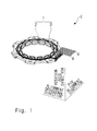
Fig. 1 is a perspective view of a resolver having a plurality of external cables attached thereto (first embodiment); -
Fig. 2 is a perspective view of the resolver having the plurality of external cables attached thereto, when viewed from another angle (first embodiment); -
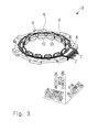
Fig. 3 is a perspective view of a stator of the resolver (first embodiment); -
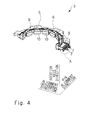
Fig. 4 is a partially cutaway perspective view ofFig. 3 (first embodiment); -
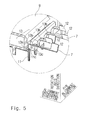
Fig. 5 is an enlarged view of a portion "A" shown inFig. 4 (first embodiment); -
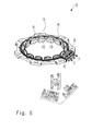
Fig. 6 is a perspective view of the stator of the resolver when viewed from another angle (first embodiment); -
Fig. 7 is a perspective view of a terminal pin (first embodiment); -
Fig. 8 is a perspective view of the terminal pin when viewed from another angle (first embodiment); -
Fig. 9 is a front view of the terminal pin (first embodiment); -
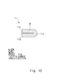
Fig. 10 is a sectional view taken along the line X-X ofFig. 9 (first embodiment); -
Fig. 11 is a partial perspective view of the stator of the resolver, and shows a state in which external cables are respectively attached to external cable connecting portions disposed on a front side (first embodiment); -
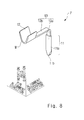
Fig. 12 is a partial perspective view of the stator of the resolver, and shows a state in which the external cable connecting portions disposed on the front side are raised upward (first embodiment); -
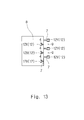
Fig. 13 is a partial plan view of the stator of the resolver, and shows gaps between external cable connecting portions disposed on a back side (first embodiment); -
Fig. 14 is a partial perspective view of the stator of the resolver, and shows a state in which the external cables are respectively attached to the external cable connecting portions disposed on the back side (first embodiment); -
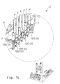
Fig. 15 is a partial perspective view of the stator of the resolver, and shows a state in which the external cable connecting portions disposed on the back side are raised upward (first embodiment); -
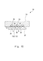
Fig. 16 is a sectional view showing a state in which the external cables are respectively attached to the external cable connecting portions disposed on the back side (first embodiment); -
Fig. 17 is a diagram corresponding to the sectional view taken along the line X-X ofFig. 9 (second embodiment); and -
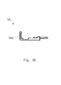
Fig. 18 is a diagram corresponding toFig. 7 ofPatent Literature 1. - A first embodiment of the present invention will be described below with reference to
Figs. 1 to 16 . - As shown in
Figs. 1 and2 , aresolver 1 serving as an angle detector includes arotor 2 which is indicated by an alternate long and two short dashes line, and astator 3 which is formed in a ring shape. Therotor 2 is fixed to an output shaft of an electric motor, which is not shown, and thereby rotates with the output shaft. Thestator 3 is fixed to, for example, a body of the electric motor. A plurality ofexternal cables 4 are connected to thestator 3. In this structure, when therotor 2 rotates relatively to thestator 3, a rotation signal corresponding to the rotation is generated in thestator 3 and is output to the outside through theexternal cables 4. - In this embodiment, a stator assembly E is composed of the plurality of
external cables 4 and thestator 3. - As shown in
Figs. 3 to 6 , thestator 3 includes astator body 5, a plurality ofstator windings 6, a plurality ofterminal pins 7, a terminalpin holding portion 8, and aninsulation cover 9. - The
stator body 5 is a stacked structure which is made of a magnetic material and is formed in a ring shape. Thestator body 5 includes a plurality ofmagnetic pole portions 10 which project toward the inner peripheral side. - The plurality of
stator windings 6 are respectively wound around the plurality ofmagnetic pole portions 10 of thestator body 5. - The plurality of
terminal pins 7 are metallic members that connect the plurality ofstator windings 6 to the plurality ofexternal cables 4, respectively. - The terminal
pin holding portion 8 is a portion that supports the plurality ofterminal pins 7. The terminalpin holding portion 8 is formed on thestator body 5. - The
insulation cover 9 is a cover that electrically isolates thestator body 5 from the plurality ofstator windings 6. In this embodiment, the terminalpin holding portion 8 and theinsulation cover 9 are integrally formed. - The terms "rotation axis direction", "pin alignment direction", and "alignment orthogonal direction" are now defined. The rotation axis direction is a direction parallel to the axis of the rotation of the
rotor 2 as shown inFigs. 1 and2 . The pin alignment direction is a direction in which the plurality ofterminal pins 7 are aligned as shown inFigs. 3 to 6 . The pin alignment direction is orthogonal to the rotation axis direction. The alignment orthogonal direction is orthogonal to each of the rotation axis direction and the pin alignment direction. - As shown in
Figs. 4 and5 , the plurality ofterminal pins 7 are held in the terminalpin holding portion 8 by insert molding. As shown inFigs. 7 to 9 , eachterminal pin 7 includes a stator winding connectingportion 11, an externalcable connecting portion 12, and an L-shapedportion 13. Eachterminal pin 7 is formed by bending a metal piece M. The stator winding connectingportion 11, the externalcable connecting portion 12, and the L-shapedportion 13 are integrally formed. - The stator winding connecting
portion 11 is a portion around which the corresponding stator winding 6 is wound. The stator winding connectingportion 11 is a portion to be connected with the corresponding stator winding 6. The stator winding connectingportion 11 is elongated along the rotation axis direction. The stator winding connectingportion 11 is formed in a double layer by folding the metal piece M. The stator winding connectingportion 11 has afold 11a which is formed when the metal piece M is folded. Thefold 11a is formed along the longitudinal direction of the stator winding connectingportion 11. Thefold 11a is formed along the rotation axis direction. The stator winding connectingportion 11 has asingle fold 11a. In other words, the stator winding connectingportion 11 is formed by folding the metal piece M only once. As a result, as shown inFig. 10 , the stator winding connectingportion 11 has a U-shaped cross-section. The stator winding connectingportion 11 has twocutting edges 11d capable of cutting the stator winding 6. Eachcutting edge 11d is formed along the rotation axis direction as shown inFig. 7 . - As shown in
Fig. 9 , adistal end 11b of the stator winding connectingportion 11 has a tapered shape when viewed along the thickness direction of thedistal end 11b of the stator winding connectingportion 11. Specifically, thedistal end 11b of the stator winding connectingportion 11 is tapered in a V-shape. The "V-shape" described herein includes not only a perfect V-shape, but also a substantial V-shape, such as an isosceles trapezoidal shape. In this embodiment, thedistal end 11b of the stator winding connectingportion 11 is tapered in an isosceles trapezoidal shape. - To connect the stator winding 6 to the stator winding connecting
portion 11 in the structure described above, an end of the stator winding 6 is wound around the stator winding connectingportion 11, and an unnecessary portion of the stator winding 6 is cut by thecutting edges 11d shown inFig. 7 . After that, electricity is discharged to thedistal end 11b of the stator winding connectingportion 11, thereby causing the stator winding connectingportion 11 to partially melt. This allows the stator winding connectingportion 11 and the stator winding 6 to be alloyed and combined at thedistal end 11b of the stator winding connectingportion 11. - The external
cable connecting portion 12 is a portion to be connected with the correspondingexternal cable 4. In this embodiment, the externalcable connecting portion 12 is a so-called open barrel type. Instead of using the open barrel type, a closed barrel type may be used as the externalcable connecting portion 12. - The L-shaped
portion 13 is a portion that joins the stator winding connectingportion 11 and the externalcable connecting portion 12 together. As shown inFigs. 7 and8 , the L-shapedportion 13 is a portion that is bent in an L-shape. The L-shapedportion 13 is composed of a winding-side L-shapedportion 13a which is disposed on the side of the stator winding connectingportion 11, and a cable-side L-shapedportion 13b which is disposed on the side of the externalcable connecting portion 12. The winding-side L-shapedportion 13a is a portion that is connected to the stator winding connectingportion 11 and extends in the rotation axis direction. The cable-side L-shapedportion 13b is a portion that is connected to the externalcable connecting portion 12 and extends in the alignment orthogonal direction. The winding-side L-shapedportion 13a is connected to the cable-side L-shapedportion 13b. - As shown in
Fig. 5 , in eachterminal pin 7, aproximal end 11c of the stator winding connectingportion 11, the winding-side L-shapedportion 13a of the L-shapedportion 13, and anend 13c on the side of the winding-side L-shapedportion 13a of the L-shapedportion 13 are housed in the terminalpin holding portion 8. The externalcable connecting portions 12 of the plurality ofterminal pins 7 are arranged in a staggered manner when viewed along the rotation axis direction. In other words, the plurality ofterminal pins 7 respectively have the cable-side L-shapedportions 13b with different lengths so that the externalcable connecting portions 12 are arranged in a staggered manner. - Next, a method for manufacturing the stator assembly E will be described with reference to
Figs. 11 to 15 . Note thatFigs. 11 to 15 illustrate the state of each externalcable connecting portion 12 before crimping, and the illustration of the state of each externalcable connecting portion 12 after crimping is omitted for convenience of illustration. - Referring first to
Fig. 11 , threeexternal cables 4 are simultaneously crimped and connected to three front-side externalcable connecting portions 12X, respectively, which serve as the externalcable connecting portions 12 disposed on the front side (on the side far from the terminal pin holding portion 8) among the plurality of externalcable connecting portions 12 arranged in the staggered manner. Next, as shown inFig. 12 , the cable-side L-shapedportions 13b of the L-shapedportions 13 of theterminal pins 7 respectively including the front-side externalcable connecting portions 12X are bent, thereby causing the front-side externalcable connecting portions 12X to be displaced so as to be raised upward. As a result, as shown inFigs. 12 and13 , gaps g are formed between three back-side externalcable connecting portions 12Y which serve as the externalcable connecting portions 12 disposed on the back side (on the side close to the terminal pin holding portion 8) among the plurality of externalcable connecting portions 12 arranged in the staggered manner. Next, as shown inFig. 14 , threeexternal cables 4 are simultaneously crimped and connected to the three back-side externalcable connecting portions 12Y, respectively. Lastly, as shown inFig. 15 , the cable-side L-shapedportions 13b of the L-shapedportions 13 of theterminal pins 7 respectively including the back-side externalcable connecting portions 12Y are bent, thereby causing the back-side externalcable connecting portions 12Y to be displaced so as to be raised upward. - The first embodiment of the present invention described above has the following features.
- (1) The
stator 3 of theresolver 1 includes: thestator body 5 including the plurality ofmagnetic pole portions 10; the plurality ofstator windings 6 respectively wound around themagnetic pole portions 10; the plurality ofterminal pins 7 each having the stator winding connectingportion 11 around which the corresponding stator winding 6 is wound and the externalcable connecting portion 12 to be connected with the correspondingexternal cable 4; and the terminalpin holding portion 8 that holds the plurality of terminal pins 7. The stator winding connectingportion 11 of eachterminal pin 7 is formed in a double layer by folding the metal piece M and has thefold 11a which is formed when the metal piece M is folded. Thefold 11a of the stator winding connectingportion 11 of eachterminal pin 7 is formed along the longitudinal direction of the stator winding connectingportion 11. According to the structure described above, the length of thefold 11a can be increased, thereby achieving an improvement in the strength of the stator winding connectingportion 11. Accordingly, an advantageous effect that the stator winding connectingportions 11 are hardly deformed is obtained even if a force that causes the stator winding connectingportions 11 to be bent in a direction orthogonal to the rotation axis direction acts on the stator winding connectingportions 11 during winding of thestator windings 6 around the stator winding connectingportions 11, or during cutting of thestator windings 6 after the winding. If necessary, refer to the fold disclosed inPatent Literature 1 shown inFig. 18 .
Further, according to the structure described above, the number of thecutting edges 11d of the metal piece M extending along the longitudinal direction of each stator winding connectingportion 11 is reduced due to the presence of thefold 11a. This prevents thestator windings 6 from being unintentionally cut when thestator windings 6 are respectively wound around the stator winding connectingportions 11. In other words, there are at least fourcutting edges 11d capable of cutting each stator winding 6 inPatent Literature 1 shown inFig. 18 , whereas in this embodiment, there are two cuttingedges 11d capable of cutting each stator winding 6. - (2) The stator winding connecting
portion 11 of eachterminal pin 7 has asingle fold 11a, and the stator winding connectingportion 11 of eachterminal pin 7 has a U-shaped cross-section. Specifically, as compared with the case where the stator winding connectingportion 11 of eachterminal pin 7 has twofolds 11a, thecutting edges 11d of the metal piece M extending along the longitudinal direction of the stator winding connectingportion 11 remain in the structure described above, which makes it possible to cut each stator winding 6 by using thecutting edges 11d. Note that in a second embodiment to be described later, there are no cuttingedges 11d capable of cutting each stator winding 6. - (3) The
distal end 11b of the stator winding connectingportion 11 of eachterminal pin 7 has a tapered shape. According to the structure described above, when the stator winding connectingportion 11 and the stator winding 6 are welded together, the area in which electricity is discharged to thedistal end 11b of the stator winding connectingportion 11 is determined, so that the melted area of thedistal end 11b of the stator winding connectingportion 11 can be stabilized. - (4) The
distal end 11b of the stator winding connectingportion 11 of eachterminal pin 7 is tapered in a V-shape. According to the structure described above, when the stator winding connectingportion 11 and the stator winding 6 are welded together, the melted area of thedistal end 11b of the stator winding connectingportion 11 can be fixed at the center in the width direction (at the center in the alignment orthogonal direction), thereby achieving stable welding. - (5) The plurality of external
cable connecting portions 12 are arranged in a staggered manner. According to the structure described above, the plurality of externalcable connecting portions 12 can be arranged at a narrow pitch. - (6) Each external
cable connecting portion 12 is an open barrel type. Alternatively, a closed barrel type may be used as each externalcable connecting portion 12. - (7) The stator assembly E includes the plurality of
external cables 4, and thestator 3 of theresolver 1, thestator 3 including: thestator body 5 including the plurality ofmagnetic pole portions 10; the plurality ofstator windings 6 respectively wound around themagnetic pole portions 10; the plurality ofterminal pins 7 each including the stator winding connectingportion 11 around which the corresponding stator winding 6 is wound and the externalcable connecting portion 12 to be connected with the correspondingexternal cable 4; and the terminalpin holding portion 8 that holds the plurality ofterminal pins 7, the plurality of externalcable connecting portions 12 being arranged in a staggered manner. The stator assembly E is manufactured by the following method. The method includes the steps of: connecting theexternal cables 4 to the front-side externalcable connecting portions 12X serving as the externalcable connecting portions 12 disposed on the front side among the plurality of externalcable connecting portions 12 arranged in the staggered manner; bending theterminal pins 7 respectively including the front-side externalcable connecting portions 12X to cause the front-side externalcable connecting portions 12X to be displaced; and connecting theexternal cables 4 to the back-side externalcable connecting portions 12Y serving as the externalcable connecting portions 12 disposed on the back side among the plurality of externalcable connecting portions 12 arranged in the staggered manner. According to the method described above, when theexternal cables 4 are respectively connected to the back-side externalcable connecting portions 12Y, the gaps g can be formed between the adjacent back-side externalcable connecting portions 12Y. These gaps g have the following technical meaning.
Fig. 16 shows a crimpingjig 30 that allows three externalcable connecting portions 12 to be crimped at the same time. The crimpingjig 30 is composed of a female-side jig 31 and a male-side jig 32. The female-side jig 31 has threerecesses 33 formed therein. The male-side jig 32 has threeprotrusions 34 formed thereon. Each externalcable connecting portion 12 crimps the correspondingexternal cable 4 when the male-side jig 32 is moved toward the female-side jig 31 in the state where the externalcable connecting portion 12 and theexternal cable 4 are set at a tip end of the correspondingprotrusion 34. In this structure, if the cable-side L-shapedportions 13b instead of the gaps g shown inFig. 13 are provided, it is necessary to formaccommodating recesses 35, each of which accommodates a corresponding one of the cable-side L-shapedportions 13b, between theadjacent recesses 33 in the female-side jig 31 as shown inFig. 16 . When theaccommodating recesses 35 are formed between theadjacent recesses 33, thin-walled portions 36 are generated between eachrecess 33 and eachaccommodating recess 35. The presence of the thin-walled portions 36 leads to a decrease in the lifetime of the female-side jig 31. On the other hand, according to the method described above, the gaps g are actively formed, to thereby eliminate the need for the accommodating recesses 35. This makes it possible to prevent the generation of the thin-walled portions 36 and to increase the lifetime of the female-side jig 31. - (8) The stator assembly E includes the plurality of
external cables 4, and thestator 3 of theresolver 1, thestator 3 including: thestator body 5 including the plurality ofmagnetic pole portions 10; the plurality ofstator windings 6 respectively wound around themagnetic pole portions 10; the plurality ofterminal pins 7 each including the stator winding connectingportion 11 around which the corresponding stator winding 6 is wound and the externalcable connecting portion 12 to be connected with the correspondingexternal cable 4; and the terminalpin holding portion 8 that holds the plurality ofterminal pins 7, the plurality of externalcable connecting portions 12 being arranged in a staggered manner. The stator assembly E is manufactured in the following manner. Theexternal cables 4 are connected to the front-side externalcable connecting portions 12X serving as the externalcable connecting portions 12 disposed on the front side among the plurality of externalcable connecting portions 12 arranged in the staggered manner. The terminal pins 7 respectively including the front-side externalcable connecting portions 12X are bent to cause the front-side externalcable connecting portions 12X to be displaced. Theexternal cables 4 are connected to the back-side externalcable connecting portions 12Y serving as the externalcable connecting portions 12 disposed on the back side among the plurality of externalcable connecting portions 12 arranged in the staggered manner. According to the structure described above, when theexternal cables 4 are respectively connected to the back-side externalcable connecting portions 12Y, the gaps g can be formed between the adjacent back-side externalcable connecting portions 12Y. - Next, a second embodiment of the present invention will be described with reference to
Fig. 17 . - In the first embodiment described above, the stator winding connecting
portion 11 has asingle fold 11 a as shown inFig. 10 . Accordingly, the stator winding connectingportion 11 has a U-shaped cross-section. On the other hand, in this embodiment, the stator winding connectingportion 11 has twofolds 11a as shown inFig. 17 . Accordingly, the stator winding connectingportion 11 has a C-shaped cross-section. Since the stator winding connectingportion 11 of this embodiment has a C-shaped cross-section, the stator winding connectingportion 11 has an improved strength against bending, as compared with the stator winding connectingportion 11 of the first embodiment. - This application is based upon and claims the benefit of priority from Japanese patent application No.
2012-080440, filed on March 30, 2012
Claims (7)
- A stator of a resolver (1), comprising:a stator body (5) including a plurality of magnetic pole portions (10);a plurality of stator windings (6) respectively wound around the magnetic pole portions (10);a plurality of terminal pins (7) each including: a stator winding connecting portion (11) around which the corresponding stator winding (6) is wound; and an external cable connecting portion (12) to be connected with an external cable (4); anda terminal pin holding portion (8) that holds the plurality of terminal pins (7), whereinthe stator winding connecting portion (11) of each of the terminal pins (7) is formed in a double layer by folding a metal piece (M), and has a fold (11a) formed when the metal piece (M) is folded, andthe fold (11a) of the stator winding connecting portion (11) of each of the terminal pins (7) is formed along a longitudinal direction of the stator winding connecting portion (11).
- The stator of a resolver according to Claim 1, wherein the stator winding connecting portion (11) of each of the terminal pins (7) has a single fold (11a), and the stator winding connecting portion (11) of each of the terminal pins (7) has a U-shaped cross-section.
- The stator of a resolver according to Claim 1 or 2, wherein a distal end (11b) of the stator winding connecting portion (11) of each of the terminal pins (7) has a tapered shape.
- The stator of a resolver according to Claim 3, wherein the distal end (11b) of the stator winding connecting portion (11) of each of the terminal pins (7) is tapered in a V-shape.
- The stator of a resolver according to any one of Claims 1 to 4, wherein the plurality of external cable connecting portions (12) are arranged in a staggered manner.
- The stator of a resolver according to Claim 5, wherein each of the external cable connecting portions (12) is an open barrel type.
- A method for manufacturing a stator assembly, the stator assembly comprising:a plurality of external cables (4); anda stator (3) of a resolver (1), the stator (3) including: a stator body (5) including a plurality of magnetic pole portions (10); a plurality of stator windings (6) respectively wound around the magnetic pole portions (10); a plurality of terminal pins (7) each including a stator winding connecting portion (11) around which the corresponding stator winding (6) is wound and an external cable connecting portion (12) to be connected with the corresponding external cable (4); and a terminal pin holding portion (8) that holds the plurality of terminal pins (7), the plurality of external cable connecting portions (12) being arranged in a staggered manner,the method comprising the steps of:connecting the external cables (4) to front-side external cable connecting portions (12X), respectively, the front-side external cable connecting portions (12X) serving as external cable connecting portions (12) disposed on a front side among the plurality of external cable connecting portions (12) arranged in the staggered manner;bending the terminal pins (7) respectively including the front-side external cable connecting portions (12X) to cause the front-side external cable connecting portions (12X) to be displaced; andconnecting the external cables (4) respectively, the back-side external cable connecting portions (12Y) serving as external cable connecting portions (12) disposed on a back side among the plurality of external cable connecting portions (12) arranged in the staggered manner.
Applications Claiming Priority (2)
| Application Number | Priority Date | Filing Date | Title |
|---|---|---|---|
| JP2012080440A JP5282153B1 (en) | 2012-03-30 | 2012-03-30 | Resolver stator and method of manufacturing stator assembly |
| PCT/JP2013/002019 WO2013145698A1 (en) | 2012-03-30 | 2013-03-25 | Stator of resolver and method for manufacturing stator structure |
Publications (3)
| Publication Number | Publication Date |
|---|---|
| EP2833523A1 true EP2833523A1 (en) | 2015-02-04 |
| EP2833523A4 EP2833523A4 (en) | 2016-10-26 |
| EP2833523B1 EP2833523B1 (en) | 2019-05-01 |
Family
ID=49259000
Family Applications (1)
| Application Number | Title | Priority Date | Filing Date |
|---|---|---|---|
| EP13767867.8A Active EP2833523B1 (en) | 2012-03-30 | 2013-03-25 | Stator of resolver and method for manufacturing stator structure |
Country Status (5)
| Country | Link |
|---|---|
| US (1) | US9435632B2 (en) |
| EP (1) | EP2833523B1 (en) |
| JP (1) | JP5282153B1 (en) |
| CN (1) | CN104205582B (en) |
| WO (1) | WO2013145698A1 (en) |
Cited By (2)
| Publication number | Priority date | Publication date | Assignee | Title |
|---|---|---|---|---|
| WO2016177536A1 (en) * | 2015-05-04 | 2016-11-10 | Zf Friedrichshafen Ag | Stator for an electrical machine having a potted interconnection device, and electrical machine having such a stator |
| EP3605800A4 (en) * | 2017-03-30 | 2020-03-25 | Mitsubishi Electric Corporation | TERMINAL DEVICE FOR A DYNAMO-ELECTRIC MACHINE AND MANUFACTURING METHOD THEREOF |
Families Citing this family (4)
| Publication number | Priority date | Publication date | Assignee | Title |
|---|---|---|---|---|
| JP6058837B1 (en) * | 2016-02-09 | 2017-01-11 | 日本航空電子工業株式会社 | Resolver stator |
| CN109256884A (en) * | 2017-10-13 | 2019-01-22 | 朱卫 | A kind of motor case produced with titanium |
| EP3493336B1 (en) * | 2017-11-29 | 2022-09-07 | Valeo Siemens eAutomotive Norway AS | A male electrical connector for a voltage converter |
| US12027931B2 (en) * | 2020-03-25 | 2024-07-02 | Magna powertrain gmbh & co kg | Resolver for an electric machine |
Family Cites Families (15)
| Publication number | Priority date | Publication date | Assignee | Title |
|---|---|---|---|---|
| US3420087A (en) | 1963-02-18 | 1969-01-07 | Amp Inc | Electrical connector means and method of manufacture |
| JPH0687162B2 (en) | 1988-02-03 | 1994-11-02 | 富士写真フイルム株式会社 | Color diffusion transfer photo film unit |
| JPH0736364U (en) * | 1993-12-10 | 1995-07-04 | 住友電装株式会社 | Terminal for high voltage resistance wire |
| JP3177144B2 (en) * | 1996-02-14 | 2001-06-18 | 矢崎総業株式会社 | Male terminal |
| JPH10309067A (en) | 1997-05-01 | 1998-11-17 | Tamagawa Seiki Co Ltd | Resolver stator structure |
| JP3428394B2 (en) * | 1997-09-24 | 2003-07-22 | 多摩川精機株式会社 | Resolver terminal pin structure |
| TW389875B (en) | 1997-09-24 | 2000-05-11 | Tamagawa Seiki Co Ltd | Terminal pin structure of resolver |
| JP3881757B2 (en) * | 1997-11-13 | 2007-02-14 | 澤藤電機株式会社 | Connection terminal for stator |
| JP2000340272A (en) | 1999-05-25 | 2000-12-08 | Tamagawa Seiki Co Ltd | Pin and winding connection structure |
| JP2006109568A (en) * | 2004-10-01 | 2006-04-20 | Mitsubishi Heavy Ind Ltd | Power generation device, grid connection method for power generation device, and grid connection control program for power generation device |
| JP4594026B2 (en) * | 2004-10-07 | 2010-12-08 | 多摩川精機株式会社 | Resolver external conductor fixing structure |
| JP2007049891A (en) * | 2005-07-11 | 2007-02-22 | Nippon Densan Corp | Stator part manufacturing method and motor |
| DE102006021898A1 (en) * | 2006-05-11 | 2007-11-22 | Zf Friedrichshafen Ag | Stator for an electric machine |
| JP5588708B2 (en) * | 2010-03-19 | 2014-09-10 | ミネベア株式会社 | Resolver stator structure |
| JP4909430B2 (en) * | 2010-05-13 | 2012-04-04 | トヨタ自動車株式会社 | Variable reluctance resolver and method for producing the same |
-
2012
- 2012-03-30 JP JP2012080440A patent/JP5282153B1/en not_active Expired - Fee Related
-
2013
- 2013-03-25 EP EP13767867.8A patent/EP2833523B1/en active Active
- 2013-03-25 WO PCT/JP2013/002019 patent/WO2013145698A1/en not_active Ceased
- 2013-03-25 CN CN201380016885.8A patent/CN104205582B/en not_active Expired - Fee Related
- 2013-03-25 US US14/387,398 patent/US9435632B2/en not_active Expired - Fee Related
Cited By (4)
| Publication number | Priority date | Publication date | Assignee | Title |
|---|---|---|---|---|
| WO2016177536A1 (en) * | 2015-05-04 | 2016-11-10 | Zf Friedrichshafen Ag | Stator for an electrical machine having a potted interconnection device, and electrical machine having such a stator |
| CN107580744A (en) * | 2015-05-04 | 2018-01-12 | Zf腓特烈斯哈芬股份公司 | Stator for electric machine with casted terminal arrangement and electric machine with such stator |
| CN107580744B (en) * | 2015-05-04 | 2020-03-13 | Zf腓特烈斯哈芬股份公司 | Stator for an electric machine and electric machine having such a stator |
| EP3605800A4 (en) * | 2017-03-30 | 2020-03-25 | Mitsubishi Electric Corporation | TERMINAL DEVICE FOR A DYNAMO-ELECTRIC MACHINE AND MANUFACTURING METHOD THEREOF |
Also Published As
| Publication number | Publication date |
|---|---|
| EP2833523B1 (en) | 2019-05-01 |
| EP2833523A4 (en) | 2016-10-26 |
| US9435632B2 (en) | 2016-09-06 |
| US20150061651A1 (en) | 2015-03-05 |
| CN104205582A (en) | 2014-12-10 |
| CN104205582B (en) | 2017-03-08 |
| WO2013145698A1 (en) | 2013-10-03 |
| JP5282153B1 (en) | 2013-09-04 |
| JP2013211990A (en) | 2013-10-10 |
Similar Documents
| Publication | Publication Date | Title |
|---|---|---|
| EP2833523B1 (en) | Stator of resolver and method for manufacturing stator structure | |
| CN104205575B (en) | The stator structure of electric rotating machine | |
| US11557934B2 (en) | Interior bus bar for electric machine winding | |
| JP5920259B2 (en) | Coil, rotating electric machine, and method of manufacturing rotating electric machine | |
| JP6638008B2 (en) | Rotating electric machine stator | |
| EP4318888A1 (en) | Stator for dynamo-electric machine, dynamo-electric machine, electric drive system, and electrically powered wheel | |
| US20150126062A1 (en) | Connection structure of outer conductor terminal to electric wire | |
| EP1246343A2 (en) | Connections of salient pole windings | |
| JP6056317B2 (en) | Stator | |
| JP5909789B2 (en) | Rotating electric machine, rotating electric stator and vehicle | |
| JP5915736B2 (en) | Rotating electric machine, rotating electric stator and vehicle | |
| JP5527050B2 (en) | Stator for rotating electric machine and method for manufacturing the same | |
| JP5909790B2 (en) | Rotating electric machine, rotating electric stator and vehicle | |
| EP3285366B1 (en) | Stator and method of manufacturing stator | |
| JP5626575B2 (en) | Rotating electrical machine, its stator and manufacturing method | |
| JP6225873B2 (en) | Connection structure of electric motor | |
| JP6216631B2 (en) | Armature and rotating machine | |
| CN114342222B (en) | Coil and rotating electrical machine | |
| EP2874283B1 (en) | Provisional terminal holding structure, and resolver comprising provisional terminal holding structure | |
| US10879748B2 (en) | Stator of rotary electric machine and rotary electric machine | |
| US20250079924A1 (en) | Stator core, stator, method of manufacturing stator core, and method of manufacturing stator | |
| JP2014135849A (en) | Stator of dynamo-electric machine | |
| JP2012244887A (en) | Segment type stator | |
| JP2013005559A (en) | Segmented stator |
Legal Events
| Date | Code | Title | Description |
|---|---|---|---|
| PUAI | Public reference made under article 153(3) epc to a published international application that has entered the european phase |
Free format text: ORIGINAL CODE: 0009012 |
|
| 17P | Request for examination filed |
Effective date: 20140930 |
|
| AK | Designated contracting states |
Kind code of ref document: A1 Designated state(s): AL AT BE BG CH CY CZ DE DK EE ES FI FR GB GR HR HU IE IS IT LI LT LU LV MC MK MT NL NO PL PT RO RS SE SI SK SM TR |
|
| AX | Request for extension of the european patent |
Extension state: BA ME |
|
| DAX | Request for extension of the european patent (deleted) | ||
| RIC1 | Information provided on ipc code assigned before grant |
Ipc: H02K 15/04 20060101ALI20160524BHEP Ipc: H02K 5/22 20060101AFI20160524BHEP Ipc: H02K 3/50 20060101ALI20160524BHEP Ipc: H02K 3/04 20060101ALI20160524BHEP |
|
| RA4 | Supplementary search report drawn up and despatched (corrected) |
Effective date: 20160922 |
|
| RIC1 | Information provided on ipc code assigned before grant |
Ipc: H02K 15/04 20060101ALI20160916BHEP Ipc: H02K 3/04 20060101ALI20160916BHEP Ipc: H02K 3/50 20060101ALI20160916BHEP Ipc: H02K 5/22 20060101AFI20160916BHEP |
|
| STAA | Information on the status of an ep patent application or granted ep patent |
Free format text: STATUS: EXAMINATION IS IN PROGRESS |
|
| 17Q | First examination report despatched |
Effective date: 20170823 |
|
| GRAP | Despatch of communication of intention to grant a patent |
Free format text: ORIGINAL CODE: EPIDOSNIGR1 |
|
| STAA | Information on the status of an ep patent application or granted ep patent |
Free format text: STATUS: GRANT OF PATENT IS INTENDED |
|
| INTG | Intention to grant announced |
Effective date: 20181113 |
|
| GRAS | Grant fee paid |
Free format text: ORIGINAL CODE: EPIDOSNIGR3 |
|
| GRAA | (expected) grant |
Free format text: ORIGINAL CODE: 0009210 |
|
| STAA | Information on the status of an ep patent application or granted ep patent |
Free format text: STATUS: THE PATENT HAS BEEN GRANTED |
|
| AK | Designated contracting states |
Kind code of ref document: B1 Designated state(s): AL AT BE BG CH CY CZ DE DK EE ES FI FR GB GR HR HU IE IS IT LI LT LU LV MC MK MT NL NO PL PT RO RS SE SI SK SM TR |
|
| REG | Reference to a national code |
Ref country code: GB Ref legal event code: FG4D |
|
| REG | Reference to a national code |
Ref country code: CH Ref legal event code: EP Ref country code: AT Ref legal event code: REF Ref document number: 1128235 Country of ref document: AT Kind code of ref document: T Effective date: 20190515 |
|
| REG | Reference to a national code |
Ref country code: DE Ref legal event code: R096 Ref document number: 602013054682 Country of ref document: DE |
|
| REG | Reference to a national code |
Ref country code: IE Ref legal event code: FG4D |
|
| REG | Reference to a national code |
Ref country code: NL Ref legal event code: MP Effective date: 20190501 |
|
| REG | Reference to a national code |
Ref country code: LT Ref legal event code: MG4D |
|
| PG25 | Lapsed in a contracting state [announced via postgrant information from national office to epo] |
Ref country code: SE Free format text: LAPSE BECAUSE OF FAILURE TO SUBMIT A TRANSLATION OF THE DESCRIPTION OR TO PAY THE FEE WITHIN THE PRESCRIBED TIME-LIMIT Effective date: 20190501 Ref country code: PT Free format text: LAPSE BECAUSE OF FAILURE TO SUBMIT A TRANSLATION OF THE DESCRIPTION OR TO PAY THE FEE WITHIN THE PRESCRIBED TIME-LIMIT Effective date: 20190901 Ref country code: NO Free format text: LAPSE BECAUSE OF FAILURE TO SUBMIT A TRANSLATION OF THE DESCRIPTION OR TO PAY THE FEE WITHIN THE PRESCRIBED TIME-LIMIT Effective date: 20190801 Ref country code: AL Free format text: LAPSE BECAUSE OF FAILURE TO SUBMIT A TRANSLATION OF THE DESCRIPTION OR TO PAY THE FEE WITHIN THE PRESCRIBED TIME-LIMIT Effective date: 20190501 Ref country code: FI Free format text: LAPSE BECAUSE OF FAILURE TO SUBMIT A TRANSLATION OF THE DESCRIPTION OR TO PAY THE FEE WITHIN THE PRESCRIBED TIME-LIMIT Effective date: 20190501 Ref country code: LT Free format text: LAPSE BECAUSE OF FAILURE TO SUBMIT A TRANSLATION OF THE DESCRIPTION OR TO PAY THE FEE WITHIN THE PRESCRIBED TIME-LIMIT Effective date: 20190501 Ref country code: HR Free format text: LAPSE BECAUSE OF FAILURE TO SUBMIT A TRANSLATION OF THE DESCRIPTION OR TO PAY THE FEE WITHIN THE PRESCRIBED TIME-LIMIT Effective date: 20190501 Ref country code: ES Free format text: LAPSE BECAUSE OF FAILURE TO SUBMIT A TRANSLATION OF THE DESCRIPTION OR TO PAY THE FEE WITHIN THE PRESCRIBED TIME-LIMIT Effective date: 20190501 Ref country code: NL Free format text: LAPSE BECAUSE OF FAILURE TO SUBMIT A TRANSLATION OF THE DESCRIPTION OR TO PAY THE FEE WITHIN THE PRESCRIBED TIME-LIMIT Effective date: 20190501 |
|
| PG25 | Lapsed in a contracting state [announced via postgrant information from national office to epo] |
Ref country code: LV Free format text: LAPSE BECAUSE OF FAILURE TO SUBMIT A TRANSLATION OF THE DESCRIPTION OR TO PAY THE FEE WITHIN THE PRESCRIBED TIME-LIMIT Effective date: 20190501 Ref country code: RS Free format text: LAPSE BECAUSE OF FAILURE TO SUBMIT A TRANSLATION OF THE DESCRIPTION OR TO PAY THE FEE WITHIN THE PRESCRIBED TIME-LIMIT Effective date: 20190501 Ref country code: BG Free format text: LAPSE BECAUSE OF FAILURE TO SUBMIT A TRANSLATION OF THE DESCRIPTION OR TO PAY THE FEE WITHIN THE PRESCRIBED TIME-LIMIT Effective date: 20190801 Ref country code: GR Free format text: LAPSE BECAUSE OF FAILURE TO SUBMIT A TRANSLATION OF THE DESCRIPTION OR TO PAY THE FEE WITHIN THE PRESCRIBED TIME-LIMIT Effective date: 20190802 |
|
| REG | Reference to a national code |
Ref country code: AT Ref legal event code: MK05 Ref document number: 1128235 Country of ref document: AT Kind code of ref document: T Effective date: 20190501 |
|
| PG25 | Lapsed in a contracting state [announced via postgrant information from national office to epo] |
Ref country code: IS Free format text: LAPSE BECAUSE OF FAILURE TO SUBMIT A TRANSLATION OF THE DESCRIPTION OR TO PAY THE FEE WITHIN THE PRESCRIBED TIME-LIMIT Effective date: 20190901 |
|
| PG25 | Lapsed in a contracting state [announced via postgrant information from national office to epo] |
Ref country code: CZ Free format text: LAPSE BECAUSE OF FAILURE TO SUBMIT A TRANSLATION OF THE DESCRIPTION OR TO PAY THE FEE WITHIN THE PRESCRIBED TIME-LIMIT Effective date: 20190501 Ref country code: AT Free format text: LAPSE BECAUSE OF FAILURE TO SUBMIT A TRANSLATION OF THE DESCRIPTION OR TO PAY THE FEE WITHIN THE PRESCRIBED TIME-LIMIT Effective date: 20190501 Ref country code: DK Free format text: LAPSE BECAUSE OF FAILURE TO SUBMIT A TRANSLATION OF THE DESCRIPTION OR TO PAY THE FEE WITHIN THE PRESCRIBED TIME-LIMIT Effective date: 20190501 Ref country code: EE Free format text: LAPSE BECAUSE OF FAILURE TO SUBMIT A TRANSLATION OF THE DESCRIPTION OR TO PAY THE FEE WITHIN THE PRESCRIBED TIME-LIMIT Effective date: 20190501 Ref country code: SK Free format text: LAPSE BECAUSE OF FAILURE TO SUBMIT A TRANSLATION OF THE DESCRIPTION OR TO PAY THE FEE WITHIN THE PRESCRIBED TIME-LIMIT Effective date: 20190501 Ref country code: RO Free format text: LAPSE BECAUSE OF FAILURE TO SUBMIT A TRANSLATION OF THE DESCRIPTION OR TO PAY THE FEE WITHIN THE PRESCRIBED TIME-LIMIT Effective date: 20190501 |
|
| REG | Reference to a national code |
Ref country code: DE Ref legal event code: R097 Ref document number: 602013054682 Country of ref document: DE |
|
| PG25 | Lapsed in a contracting state [announced via postgrant information from national office to epo] |
Ref country code: IT Free format text: LAPSE BECAUSE OF FAILURE TO SUBMIT A TRANSLATION OF THE DESCRIPTION OR TO PAY THE FEE WITHIN THE PRESCRIBED TIME-LIMIT Effective date: 20190501 Ref country code: SM Free format text: LAPSE BECAUSE OF FAILURE TO SUBMIT A TRANSLATION OF THE DESCRIPTION OR TO PAY THE FEE WITHIN THE PRESCRIBED TIME-LIMIT Effective date: 20190501 |
|
| PLBE | No opposition filed within time limit |
Free format text: ORIGINAL CODE: 0009261 |
|
| STAA | Information on the status of an ep patent application or granted ep patent |
Free format text: STATUS: NO OPPOSITION FILED WITHIN TIME LIMIT |
|
| PG25 | Lapsed in a contracting state [announced via postgrant information from national office to epo] |
Ref country code: TR Free format text: LAPSE BECAUSE OF FAILURE TO SUBMIT A TRANSLATION OF THE DESCRIPTION OR TO PAY THE FEE WITHIN THE PRESCRIBED TIME-LIMIT Effective date: 20190501 |
|
| 26N | No opposition filed |
Effective date: 20200204 |
|
| PG25 | Lapsed in a contracting state [announced via postgrant information from national office to epo] |
Ref country code: PL Free format text: LAPSE BECAUSE OF FAILURE TO SUBMIT A TRANSLATION OF THE DESCRIPTION OR TO PAY THE FEE WITHIN THE PRESCRIBED TIME-LIMIT Effective date: 20190501 |
|
| PG25 | Lapsed in a contracting state [announced via postgrant information from national office to epo] |
Ref country code: SI Free format text: LAPSE BECAUSE OF FAILURE TO SUBMIT A TRANSLATION OF THE DESCRIPTION OR TO PAY THE FEE WITHIN THE PRESCRIBED TIME-LIMIT Effective date: 20190501 |
|
| PG25 | Lapsed in a contracting state [announced via postgrant information from national office to epo] |
Ref country code: MC Free format text: LAPSE BECAUSE OF FAILURE TO SUBMIT A TRANSLATION OF THE DESCRIPTION OR TO PAY THE FEE WITHIN THE PRESCRIBED TIME-LIMIT Effective date: 20190501 |
|
| REG | Reference to a national code |
Ref country code: CH Ref legal event code: PL |
|
| REG | Reference to a national code |
Ref country code: BE Ref legal event code: MM Effective date: 20200331 |
|
| PG25 | Lapsed in a contracting state [announced via postgrant information from national office to epo] |
Ref country code: LU Free format text: LAPSE BECAUSE OF NON-PAYMENT OF DUE FEES Effective date: 20200325 |
|
| PG25 | Lapsed in a contracting state [announced via postgrant information from national office to epo] |
Ref country code: IE Free format text: LAPSE BECAUSE OF NON-PAYMENT OF DUE FEES Effective date: 20200325 Ref country code: LI Free format text: LAPSE BECAUSE OF NON-PAYMENT OF DUE FEES Effective date: 20200331 Ref country code: FR Free format text: LAPSE BECAUSE OF NON-PAYMENT OF DUE FEES Effective date: 20200331 Ref country code: CH Free format text: LAPSE BECAUSE OF NON-PAYMENT OF DUE FEES Effective date: 20200331 |
|
| PG25 | Lapsed in a contracting state [announced via postgrant information from national office to epo] |
Ref country code: BE Free format text: LAPSE BECAUSE OF NON-PAYMENT OF DUE FEES Effective date: 20200331 |
|
| GBPC | Gb: european patent ceased through non-payment of renewal fee |
Effective date: 20200325 |
|
| PG25 | Lapsed in a contracting state [announced via postgrant information from national office to epo] |
Ref country code: GB Free format text: LAPSE BECAUSE OF NON-PAYMENT OF DUE FEES Effective date: 20200325 |
|
| PGFP | Annual fee paid to national office [announced via postgrant information from national office to epo] |
Ref country code: DE Payment date: 20220203 Year of fee payment: 10 |
|
| PG25 | Lapsed in a contracting state [announced via postgrant information from national office to epo] |
Ref country code: MT Free format text: LAPSE BECAUSE OF FAILURE TO SUBMIT A TRANSLATION OF THE DESCRIPTION OR TO PAY THE FEE WITHIN THE PRESCRIBED TIME-LIMIT Effective date: 20190501 Ref country code: CY Free format text: LAPSE BECAUSE OF FAILURE TO SUBMIT A TRANSLATION OF THE DESCRIPTION OR TO PAY THE FEE WITHIN THE PRESCRIBED TIME-LIMIT Effective date: 20190501 |
|
| PG25 | Lapsed in a contracting state [announced via postgrant information from national office to epo] |
Ref country code: MK Free format text: LAPSE BECAUSE OF FAILURE TO SUBMIT A TRANSLATION OF THE DESCRIPTION OR TO PAY THE FEE WITHIN THE PRESCRIBED TIME-LIMIT Effective date: 20190501 |
|
| REG | Reference to a national code |
Ref country code: DE Ref legal event code: R119 Ref document number: 602013054682 Country of ref document: DE |
|
| PG25 | Lapsed in a contracting state [announced via postgrant information from national office to epo] |
Ref country code: DE Free format text: LAPSE BECAUSE OF NON-PAYMENT OF DUE FEES Effective date: 20231003 |