EP2833470A1 - Interlocking device for battery unit board - Google Patents
Interlocking device for battery unit board Download PDFInfo
- Publication number
- EP2833470A1 EP2833470A1 EP12872718.7A EP12872718A EP2833470A1 EP 2833470 A1 EP2833470 A1 EP 2833470A1 EP 12872718 A EP12872718 A EP 12872718A EP 2833470 A1 EP2833470 A1 EP 2833470A1
- Authority
- EP
- European Patent Office
- Prior art keywords
- switch
- battery unit
- interlocking
- battery
- interlocking device
- Prior art date
- Legal status (The legal status is an assumption and is not a legal conclusion. Google has not performed a legal analysis and makes no representation as to the accuracy of the status listed.)
- Withdrawn
Links
Images


Classifications
-
- H—ELECTRICITY
- H01—ELECTRIC ELEMENTS
- H01M—PROCESSES OR MEANS, e.g. BATTERIES, FOR THE DIRECT CONVERSION OF CHEMICAL ENERGY INTO ELECTRICAL ENERGY
- H01M50/00—Constructional details or processes of manufacture of the non-active parts of electrochemical cells other than fuel cells, e.g. hybrid cells
- H01M50/20—Mountings; Secondary casings or frames; Racks, modules or packs; Suspension devices; Shock absorbers; Transport or carrying devices; Holders
-
- H—ELECTRICITY
- H01—ELECTRIC ELEMENTS
- H01M—PROCESSES OR MEANS, e.g. BATTERIES, FOR THE DIRECT CONVERSION OF CHEMICAL ENERGY INTO ELECTRICAL ENERGY
- H01M10/00—Secondary cells; Manufacture thereof
- H01M10/42—Methods or arrangements for servicing or maintenance of secondary cells or secondary half-cells
- H01M10/48—Accumulators combined with arrangements for measuring, testing or indicating the condition of cells, e.g. the level or density of the electrolyte
-
- H—ELECTRICITY
- H01—ELECTRIC ELEMENTS
- H01M—PROCESSES OR MEANS, e.g. BATTERIES, FOR THE DIRECT CONVERSION OF CHEMICAL ENERGY INTO ELECTRICAL ENERGY
- H01M10/00—Secondary cells; Manufacture thereof
- H01M10/04—Construction or manufacture in general
- H01M10/0445—Multimode batteries, e.g. containing auxiliary cells or electrodes switchable in parallel or series connections
-
- H—ELECTRICITY
- H01—ELECTRIC ELEMENTS
- H01M—PROCESSES OR MEANS, e.g. BATTERIES, FOR THE DIRECT CONVERSION OF CHEMICAL ENERGY INTO ELECTRICAL ENERGY
- H01M10/00—Secondary cells; Manufacture thereof
- H01M10/42—Methods or arrangements for servicing or maintenance of secondary cells or secondary half-cells
- H01M10/4207—Methods or arrangements for servicing or maintenance of secondary cells or secondary half-cells for several batteries or cells simultaneously or sequentially
-
- H—ELECTRICITY
- H01—ELECTRIC ELEMENTS
- H01M—PROCESSES OR MEANS, e.g. BATTERIES, FOR THE DIRECT CONVERSION OF CHEMICAL ENERGY INTO ELECTRICAL ENERGY
- H01M10/00—Secondary cells; Manufacture thereof
- H01M10/42—Methods or arrangements for servicing or maintenance of secondary cells or secondary half-cells
- H01M10/48—Accumulators combined with arrangements for measuring, testing or indicating the condition of cells, e.g. the level or density of the electrolyte
- H01M10/488—Cells or batteries combined with indicating means for external visualization of the condition, e.g. by change of colour or of light density
-
- H—ELECTRICITY
- H01—ELECTRIC ELEMENTS
- H01M—PROCESSES OR MEANS, e.g. BATTERIES, FOR THE DIRECT CONVERSION OF CHEMICAL ENERGY INTO ELECTRICAL ENERGY
- H01M50/00—Constructional details or processes of manufacture of the non-active parts of electrochemical cells other than fuel cells, e.g. hybrid cells
- H01M50/20—Mountings; Secondary casings or frames; Racks, modules or packs; Suspension devices; Shock absorbers; Transport or carrying devices; Holders
- H01M50/262—Mountings; Secondary casings or frames; Racks, modules or packs; Suspension devices; Shock absorbers; Transport or carrying devices; Holders with fastening means, e.g. locks
- H01M50/264—Mountings; Secondary casings or frames; Racks, modules or packs; Suspension devices; Shock absorbers; Transport or carrying devices; Holders with fastening means, e.g. locks for cells or batteries, e.g. straps, tie rods or peripheral frames
-
- H—ELECTRICITY
- H01—ELECTRIC ELEMENTS
- H01M—PROCESSES OR MEANS, e.g. BATTERIES, FOR THE DIRECT CONVERSION OF CHEMICAL ENERGY INTO ELECTRICAL ENERGY
- H01M50/00—Constructional details or processes of manufacture of the non-active parts of electrochemical cells other than fuel cells, e.g. hybrid cells
- H01M50/50—Current conducting connections for cells or batteries
- H01M50/502—Interconnectors for connecting terminals of adjacent batteries; Interconnectors for connecting cells outside a battery casing
- H01M50/509—Interconnectors for connecting terminals of adjacent batteries; Interconnectors for connecting cells outside a battery casing characterised by the type of connection, e.g. mixed connections
- H01M50/51—Connection only in series
-
- H—ELECTRICITY
- H01—ELECTRIC ELEMENTS
- H01M—PROCESSES OR MEANS, e.g. BATTERIES, FOR THE DIRECT CONVERSION OF CHEMICAL ENERGY INTO ELECTRICAL ENERGY
- H01M50/00—Constructional details or processes of manufacture of the non-active parts of electrochemical cells other than fuel cells, e.g. hybrid cells
- H01M50/50—Current conducting connections for cells or batteries
- H01M50/572—Means for preventing undesired use or discharge
- H01M50/574—Devices or arrangements for the interruption of current
-
- H—ELECTRICITY
- H01—ELECTRIC ELEMENTS
- H01M—PROCESSES OR MEANS, e.g. BATTERIES, FOR THE DIRECT CONVERSION OF CHEMICAL ENERGY INTO ELECTRICAL ENERGY
- H01M2200/00—Safety devices for primary or secondary batteries
-
- Y—GENERAL TAGGING OF NEW TECHNOLOGICAL DEVELOPMENTS; GENERAL TAGGING OF CROSS-SECTIONAL TECHNOLOGIES SPANNING OVER SEVERAL SECTIONS OF THE IPC; TECHNICAL SUBJECTS COVERED BY FORMER USPC CROSS-REFERENCE ART COLLECTIONS [XRACs] AND DIGESTS
- Y02—TECHNOLOGIES OR APPLICATIONS FOR MITIGATION OR ADAPTATION AGAINST CLIMATE CHANGE
- Y02E—REDUCTION OF GREENHOUSE GAS [GHG] EMISSIONS, RELATED TO ENERGY GENERATION, TRANSMISSION OR DISTRIBUTION
- Y02E60/00—Enabling technologies; Technologies with a potential or indirect contribution to GHG emissions mitigation
- Y02E60/10—Energy storage using batteries
Definitions
- the present invention relates to an interlocking device for a battery unit board that stores a battery unit and includes a switch opening and closing a DC circuit.
- a switch that opens and closes a DC circuit is connected to a battery unit board storing a battery unit (battery module) in which plural battery cells are connected in series (for example, see Patent Document 1).
- a front plate or a side plate is removed to check discoloration or damage of the battery units that are stacked in multiple stages.
- a switch is opened, the battery unit is removed from a connection conductor, and the battery unit is exchanged.
- the battery unit is removed without opening the switch. In view of this, an interlocking device between the switch and the battery unit with a simple configuration has been demanded.
- Patent Document 1 Japanese Patent Disclosure (Kokai) P2009-104808
- a problem to be solved by the present invention is to provide an interlocking device for a battery unit board that can allow predetermined battery units, which are stacked in multiple stages, to be removed, when a switch is opened.
- an interlocking device for a battery unit board includes: a housing; battery units that are stacked in multiple stages in the housing; a switch that is connected to a DC circuit to which the battery units are connected in series; and an interlocking mechanism that allows the movement of the battery units when the switch is opened, and that inhibits the movement of the battery units when the switch is closed.
- the predetermined battery units that are stacked in the multiple stages can be removed, and connected with a simple configuration, when the switch is opened.
- FIG. 1 is a diagram illustrating an electric circuit of a battery unit board according to the first embodiment of the present invention
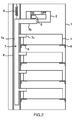
- FIG. 2 is a front view illustrating a configuration of the interlocking device for the battery unit board according to the first embodiment of the present invention
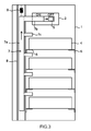
- FIG. 3 is a front view for describing an operation of the interlocking device for the battery unit board according to the first embodiment of the present invention.
- plural battery units 4 that are connected to a switch 2 in series with a connection conductor 3 are stored in a housing 1.
- the switch 2 is connected to an output side of the DC circuit formed by the battery units 4 for opening and closing an external circuit.
- Plural battery cells are connected in series in each of the battery units 4.
- the switch 2 is mounted at an upper side of the housing 1.
- An operation handle 5 that is movable in a horizontal direction for performing an open/close operation is provided to the switch 2.
- the battery units 4 are stacked in multiple stages in the vertical direction below the switch 2, and placed on a pair of L-shaped placing plates 6 provided on a side face. The battery units 4 can be drawn in the near direction of the sheet surface.
- An interlocking plate 7 is provided at the left side of the housing 1.
- the interlocking plate 7 is disposed in the vertical direction, and includes a base portion 7a that is movable on a guide 8 in the vertical direction, a horizontally arranged handle contact portion 7b that is consecutively provided at the upper part of the base portion 7a and that is in contact with the operation handle 5, and battery contact portions 7c that are provided downward from the middle part of the base portion 7a in multiple stages and that are in contact with the bottom surfaces of the battery units 4.
- a spring 9 that biases the interlocking plate 7 in the vertical direction is provided between the base portion 7a and the ceiling portion of the housing 1.
- the operation handle 5 when the operation handle 5 is moved to the right for opening the switch 2, the operation handle 5 is detached from the handle contact portion 7b.
- the base portion 7a can be moved upward with spring force of the spring 9.
- the battery contact portions 7c also move upward, and are detached from the bottom surfaces of the battery units 4.
- the movement of the interlocking plate 7 is restricted according to the position of the operation handle 5, and when the switch 2 is opened, the battery contact portion 7c that hinders the drawing direction of the battery unit 4 can be released. Accordingly, the battery unit 4 that needs to be exchanged can be removed, and a new battery unit can be connected. After the exchange, the interlocking plate 7 is moved downward, the lock pin is set, and then, the operation handle 5 is operated.
- the interlocking plate 7 is referred to as an interlocking mechanism that allows the movement of the battery unit 4 when the switch 2 is opened, and that inhibits the movement of the battery unit 4 when the switch 2 is closed.
- the interlocking plate 7 that can be moved when the operation handle 5 of the switch 2 is opened is provided. Therefore, the battery unit 4 can be removed, and can be connected with the DC circuit being shut down.
- the interlocking device also provides an interlocking with simple configuration.
- the movement of the battery unit 4 is restricted with a mechanical interlocking.
- a display device or an alarm device that receives an electric supply from the switch 2 can issue an alarm signal such as a flickering display or an alarm sound when the front plate or the like of the housing 1 is removed with the switch 2 being closed.
- the power source system has a simple circuit, since it is in interlocking with the switch 2.
- FIG. 4 is a front view illustrating an essential part in a configuration of an interlocking device for a battery unit board according to the second embodiment of the present invention.
- the different point between the second embodiment and the first embodiment is that the second embodiment provides an electric interlocking.
- the components similar to those in the first embodiment are identified by the same reference numerals, and the detailed description thereof will be skipped.
- the interlocking device includes an electromagnetic operation mechanism 11 having a locking rod 10 that moves in a horizontal direction.
- the electromagnetic operation mechanism 11 receives an electric supply from the switch 2 with a control line 12.
- the electromagnetic operation mechanism 11 operates, whereby the locking rod 10 is brought into contact with the bottom surface of the battery unit 4 to hinder the drawing direction.
- the switch 2 is opened, the power supply of the electromagnetic operation mechanism 11 is lost, and non-excitation state is generated. Therefore, the locking rod 10 moves backward, whereby the battery unit 4 can be removed.
- the locking rod 10 is referred to as an interlocking mechanism that allows the movement of the battery unit 4 when the switch 2 is opened, and that inhibits the movement of the battery unit 4 when the switch 2 is closed.
- the effect obtained by the first embodiment can also be obtained even by the electric interlocking.
- FIG. 5 is a backside view illustrating an essential part in a configuration of an interlocking device for a battery unit board according to the third embodiment of the present invention.
- the different point between the third embodiment and the second embodiment is that an electric interlocking is also provided to a terminal of the battery unit in the third embodiment.
- the components similar to those in the second embodiment are identified by the same reference numerals, and the detailed description thereof will be skipped.
- a terminal 13 of the battery unit 4 is provided on the back surface of the housing 1.
- An electromagnetic operation mechanism 11 having a shielding plate 14 that vertically moves is also provided.
- the terminal 13 is covered by the shielding plate 14 by the operation of the electromagnetic operation mechanism 11, when the switch 2 is closed.
- the electromagnetic operation mechanism 11 becomes a non-excitation state, whereby the terminal 13 is released.
- the effect obtained by the second embodiment can be obtained, and further, a connection operation can be carried out at the side of the terminal 13 of the battery unit 4, when the switch 2 is opened.
- predetermined battery units that are stacked in multiple stages can be removed, and connected with a simple configuration, when the switch is opened.
Landscapes
- Chemical & Material Sciences (AREA)
- Chemical Kinetics & Catalysis (AREA)
- Electrochemistry (AREA)
- General Chemical & Material Sciences (AREA)
- Engineering & Computer Science (AREA)
- Manufacturing & Machinery (AREA)
- Battery Mounting, Suspending (AREA)
- Secondary Cells (AREA)
Abstract
Description
- The present invention relates to an interlocking device for a battery unit board that stores a battery unit and includes a switch opening and closing a DC circuit.
- Conventionally, a switch that opens and closes a DC circuit is connected to a battery unit board storing a battery unit (battery module) in which plural battery cells are connected in series (for example, see Patent Document 1).
- For checking the battery unit board described above, a front plate or a side plate is removed to check discoloration or damage of the battery units that are stacked in multiple stages. For the battery unit that needs to be exchanged, a switch is opened, the battery unit is removed from a connection conductor, and the battery unit is exchanged. However, there may be a case in which the battery unit is removed without opening the switch. In view of this, an interlocking device between the switch and the battery unit with a simple configuration has been demanded.
- Patent Document 1: Japanese Patent Disclosure (Kokai)
P2009-104808 - A problem to be solved by the present invention is to provide an interlocking device for a battery unit board that can allow predetermined battery units, which are stacked in multiple stages, to be removed, when a switch is opened.
- In order to solve the above problem, an interlocking device for a battery unit board according to an embodiment includes: a housing; battery units that are stacked in multiple stages in the housing; a switch that is connected to a DC circuit to which the battery units are connected in series; and an interlocking mechanism that allows the movement of the battery units when the switch is opened, and that inhibits the movement of the battery units when the switch is closed.
- According to the interlocking device for the battery unit board of the present invention, the predetermined battery units that are stacked in the multiple stages can be removed, and connected with a simple configuration, when the switch is opened.
-
-
FIG. 1 is a diagram illustrating an electric circuit of a battery unit board according to a first embodiment of the present invention. -
FIG. 2 is a front view illustrating a configuration of an interlocking device for the battery unit board according to the first embodiment of the present invention. -
FIG. 3 is a front view for describing an operation of the interlocking device for the battery unit board according to the first embodiment of the present invention. -
FIG. 4 is a front view illustrating an essential part in a configuration of an interlocking device for the battery unit board according to a second embodiment of the present invention. -
FIG. 5 is a backside view illustrating an essential part of a configuration of an interlocking device for the battery unit board according to a third embodiment of the present invention. - Embodiments of the present invention will be described below with reference to the drawings.
- Firstly, an interlocking device for a battery unit board according to a first embodiment of the present invention will be described with reference to
FIGS. 1 to 3 .FIG. 1 is a diagram illustrating an electric circuit of a battery unit board according to the first embodiment of the present invention,FIG. 2 is a front view illustrating a configuration of the interlocking device for the battery unit board according to the first embodiment of the present invention, andFIG. 3 is a front view for describing an operation of the interlocking device for the battery unit board according to the first embodiment of the present invention. - As illustrated in
FIG. 1 ,plural battery units 4 that are connected to aswitch 2 in series with aconnection conductor 3 are stored in ahousing 1. Theswitch 2 is connected to an output side of the DC circuit formed by thebattery units 4 for opening and closing an external circuit. Plural battery cells are connected in series in each of thebattery units 4. - As illustrated in
FIG. 2 , theswitch 2 is mounted at an upper side of thehousing 1. Anoperation handle 5 that is movable in a horizontal direction for performing an open/close operation is provided to theswitch 2. Thebattery units 4 are stacked in multiple stages in the vertical direction below theswitch 2, and placed on a pair of L-shaped placing plates 6 provided on a side face. Thebattery units 4 can be drawn in the near direction of the sheet surface. - An interlocking
plate 7 is provided at the left side of thehousing 1. The interlockingplate 7 is disposed in the vertical direction, and includes abase portion 7a that is movable on aguide 8 in the vertical direction, a horizontally arrangedhandle contact portion 7b that is consecutively provided at the upper part of thebase portion 7a and that is in contact with theoperation handle 5, andbattery contact portions 7c that are provided downward from the middle part of thebase portion 7a in multiple stages and that are in contact with the bottom surfaces of thebattery units 4. Aspring 9 that biases the interlockingplate 7 in the vertical direction is provided between thebase portion 7a and the ceiling portion of thehousing 1. - Next, an operation of the interlocking
plate 7 will be described with reference toFIG. 3 . - As illustrated in
FIG. 3 , when theoperation handle 5 is moved to the right for opening theswitch 2, theoperation handle 5 is detached from thehandle contact portion 7b. When a lock pin that is not illustrated and that fixes the interlockingplate 7 to a fixing member of thehousing 1 is released, thebase portion 7a can be moved upward with spring force of thespring 9. Simultaneously, thebattery contact portions 7c also move upward, and are detached from the bottom surfaces of thebattery units 4. - With this configuration, the movement of the
interlocking plate 7 is restricted according to the position of theoperation handle 5, and when theswitch 2 is opened, thebattery contact portion 7c that hinders the drawing direction of thebattery unit 4 can be released. Accordingly, thebattery unit 4 that needs to be exchanged can be removed, and a new battery unit can be connected. After the exchange, theinterlocking plate 7 is moved downward, the lock pin is set, and then, theoperation handle 5 is operated. - The
interlocking plate 7 is referred to as an interlocking mechanism that allows the movement of thebattery unit 4 when theswitch 2 is opened, and that inhibits the movement of thebattery unit 4 when theswitch 2 is closed. - According to the interlocking device for a battery unit board according to the first embodiment, the
interlocking plate 7 that can be moved when theoperation handle 5 of theswitch 2 is opened is provided. Therefore, thebattery unit 4 can be removed, and can be connected with the DC circuit being shut down. The interlocking device also provides an interlocking with simple configuration. - In the above first embodiment, the movement of the
battery unit 4 is restricted with a mechanical interlocking. A display device or an alarm device that receives an electric supply from theswitch 2 can issue an alarm signal such as a flickering display or an alarm sound when the front plate or the like of thehousing 1 is removed with theswitch 2 being closed. The power source system has a simple circuit, since it is in interlocking with theswitch 2. - Next, an interlocking device for a battery unit board according to a second embodiment of the present invention will be described with reference to
FIG. 4. FIG. 4 is a front view illustrating an essential part in a configuration of an interlocking device for a battery unit board according to the second embodiment of the present invention. The different point between the second embodiment and the first embodiment is that the second embodiment provides an electric interlocking. InFIG. 4 , the components similar to those in the first embodiment are identified by the same reference numerals, and the detailed description thereof will be skipped. - As illustrated in
FIG. 4 , the interlocking device includes anelectromagnetic operation mechanism 11 having alocking rod 10 that moves in a horizontal direction. Theelectromagnetic operation mechanism 11 receives an electric supply from theswitch 2 with acontrol line 12. Thus, when theswitch 2 is closed, theelectromagnetic operation mechanism 11 operates, whereby thelocking rod 10 is brought into contact with the bottom surface of thebattery unit 4 to hinder the drawing direction. When theswitch 2 is opened, the power supply of theelectromagnetic operation mechanism 11 is lost, and non-excitation state is generated. Therefore, thelocking rod 10 moves backward, whereby thebattery unit 4 can be removed. - The
locking rod 10 is referred to as an interlocking mechanism that allows the movement of thebattery unit 4 when theswitch 2 is opened, and that inhibits the movement of thebattery unit 4 when theswitch 2 is closed. - According to the interlocking device for a battery unit board according to the above second embodiment, the effect obtained by the first embodiment can also be obtained even by the electric interlocking.
- Next, an interlocking device for a battery unit board according to a third embodiment of the present invention will be described with reference to
FIG. 5. FIG. 5 is a backside view illustrating an essential part in a configuration of an interlocking device for a battery unit board according to the third embodiment of the present invention. The different point between the third embodiment and the second embodiment is that an electric interlocking is also provided to a terminal of the battery unit in the third embodiment. InFIG. 5 , the components similar to those in the second embodiment are identified by the same reference numerals, and the detailed description thereof will be skipped. - As illustrated in
FIG. 5 , aterminal 13 of thebattery unit 4 is provided on the back surface of thehousing 1. Anelectromagnetic operation mechanism 11 having a shieldingplate 14 that vertically moves is also provided. The terminal 13 is covered by the shieldingplate 14 by the operation of theelectromagnetic operation mechanism 11, when theswitch 2 is closed. When theswitch 2 is opened, theelectromagnetic operation mechanism 11 becomes a non-excitation state, whereby the terminal 13 is released. - According to the interlocking device for a battery unit board according to the above third embodiment, the effect obtained by the second embodiment can be obtained, and further, a connection operation can be carried out at the side of the terminal 13 of the
battery unit 4, when theswitch 2 is opened. - According to the embodiments described above, predetermined battery units that are stacked in multiple stages can be removed, and connected with a simple configuration, when the switch is opened.
- While certain embodiments of the present invention have been described, these embodiments have been presented by way of example only, and are not intended to limit the scope of the inventions. Indeed, the novel embodiments described herein may be embodied in a variety of other forms; furthermore, various omissions, substitutions, and changes in the form of the embodiments described herein may be made without departing from the spirit of the inventions. The accompanying claims and their equivalents are intended to cover such forms or modifications as would fall within the scope and spirit of the inventions.
-
- 1
- HOUSING
- 2
- SWITCH
- 3
- CONNECTION CONDUCTOR
- 4
- BATTERY UNIT
- 5
- OPERATION HANDLE
- 6
- PLACING PLATE
- 7
- INTERLOCKING PLATE
- 7a
- BASE PORTION
- 7b
- HANDLE CONTACT PORTION
- 7c
- BATTERY CONTACT PORTION
- 8
- GUIDE
- 9
- SPRING
- 10
- LOCKING ROD
- 11
- ELECTROMAGNETIC OPERATION MECHANISM
- 12
- CONTROL LINE
- 13
- TERMINAL
- 14
- SHIELDING PLATE
Claims (6)
- An interlocking device for a battery unit board comprising:a housing;a battery unit that is arranged in the housing;a switch that is electrically connected to the battery unit; andan interlocking mechanism that allows the movement of the battery unit when the switch is opened, and that inhibits the battery unit from being drawn from the housing when the switch is closed.
- The interlocking device for a battery unit board according to claim 1, wherein
the interlocking mechanism includes an interlocking plate whose movement is inhibited according to a position of an operation handle of the switch, wherein
when the switch is closed, a battery contact portion of the interlocking plate is in contact with a bottom surface of the battery unit in a drawing direction, and
when the switch is opened, the battery contact portion is released from the bottom surface. - The interlocking device for a battery unit board according to claim 1, wherein
the interlocking mechanism includes an electromagnetic operation mechanism that receives an electric supply from the switch, and a locking rod that operates with the electromagnetic operation mechanism, wherein
when the switch is closed, the electromagnetic operation mechanism operates to bring the locking rod into contact with a bottom surface of the battery unit in a drawing direction, and
when the switch is opened, the electromagnetic operation mechanism becomes a non-excitation state, and the locking rod is released from the bottom surface. - The interlocking device for a battery unit board according to claim 1, wherein
the interlocking mechanism includes an electromagnetic operation mechanism that receives an electric supply from the switch, and a shielding plate that operates with the electromagnetic operation mechanism, wherein
when the switch is closed, the electromagnetic operation mechanism operates to cover a terminal of the battery unit by the shielding plate, and
when the switch is opened, the electromagnetic operation mechanism becomes a non-excitation state, and the shielding plate is released from the terminal. - The interlocking device for a battery unit board according to any one of claims 1 to 4, wherein
a device that receives an electric supply from the switch issues an alarm signal, when the housing is opened. - The interlocking device for a battery unit board according to any one of claims 1 to 5, wherein
the battery units are stacked in the housing in multiple stages, and the battery units are connected in series.
Applications Claiming Priority (2)
| Application Number | Priority Date | Filing Date | Title |
|---|---|---|---|
| JP2012078373A JP6118032B2 (en) | 2012-03-29 | 2012-03-29 | Battery unit panel interlock device |
| PCT/JP2012/008153 WO2013145058A1 (en) | 2012-03-29 | 2012-12-20 | Interlocking device for battery unit board |
Publications (2)
| Publication Number | Publication Date |
|---|---|
| EP2833470A1 true EP2833470A1 (en) | 2015-02-04 |
| EP2833470A4 EP2833470A4 (en) | 2015-11-11 |
Family
ID=49258428
Family Applications (1)
| Application Number | Title | Priority Date | Filing Date |
|---|---|---|---|
| EP12872718.7A Withdrawn EP2833470A4 (en) | 2012-03-29 | 2012-12-20 | Interlocking device for battery unit board |
Country Status (6)
| Country | Link |
|---|---|
| US (1) | US20150010796A1 (en) |
| EP (1) | EP2833470A4 (en) |
| JP (1) | JP6118032B2 (en) |
| KR (1) | KR20140137391A (en) |
| CN (1) | CN104221207A (en) |
| WO (1) | WO2013145058A1 (en) |
Families Citing this family (3)
| Publication number | Priority date | Publication date | Assignee | Title |
|---|---|---|---|---|
| JP6102541B2 (en) * | 2013-06-13 | 2017-03-29 | 住友電気工業株式会社 | Storage device and storage battery replacement method |
| CN114030383B (en) * | 2021-10-15 | 2024-04-05 | 智新控制系统有限公司 | High-voltage interlocking detection system and method |
| KR102713964B1 (en) * | 2023-06-14 | 2024-10-11 | 주식회사 엘지에너지솔루션 | Battery storage system and battery protecting unit |
Family Cites Families (9)
| Publication number | Priority date | Publication date | Assignee | Title |
|---|---|---|---|---|
| JPH01100999A (en) * | 1987-10-14 | 1989-04-19 | Matsushita Electric Ind Co Ltd | Radio communication equipment |
| JP2808284B2 (en) * | 1988-08-23 | 1998-10-08 | 旭光学工業株式会社 | Battery lid opening and closing device |
| JPH06338306A (en) * | 1993-05-27 | 1994-12-06 | Fujitsu Ltd | Battery driving equipment having lock mechanism |
| WO2000051194A1 (en) * | 1999-02-22 | 2000-08-31 | Fujitsu Limited | Battery extraction preventing device |
| JP4975260B2 (en) * | 2004-10-08 | 2012-07-11 | 本田技研工業株式会社 | Interlock structure of electrical box |
| CN100544070C (en) * | 2004-10-08 | 2009-09-23 | 本田技研工业株式会社 | Battery box structure, interlocking structure of electric box and electric box structure |
| JP2009104808A (en) | 2007-10-19 | 2009-05-14 | Toshiba Corp | Lead-acid battery device |
| JP2011076775A (en) * | 2009-09-29 | 2011-04-14 | Fujifilm Corp | Battery holding structure, and electronic equipment equipped with the same |
| US8323814B2 (en) * | 2010-03-31 | 2012-12-04 | Cooper Technologies Company | Battery safety interlock for intrinsically safe electronic devices |
-
2012
- 2012-03-29 JP JP2012078373A patent/JP6118032B2/en active Active
- 2012-12-20 EP EP12872718.7A patent/EP2833470A4/en not_active Withdrawn
- 2012-12-20 KR KR1020147026740A patent/KR20140137391A/en not_active Withdrawn
- 2012-12-20 CN CN201280072077.9A patent/CN104221207A/en active Pending
- 2012-12-20 WO PCT/JP2012/008153 patent/WO2013145058A1/en not_active Ceased
-
2014
- 2014-09-25 US US14/496,095 patent/US20150010796A1/en not_active Abandoned
Also Published As
| Publication number | Publication date |
|---|---|
| JP6118032B2 (en) | 2017-04-19 |
| WO2013145058A1 (en) | 2013-10-03 |
| CN104221207A (en) | 2014-12-17 |
| JP2013206880A (en) | 2013-10-07 |
| US20150010796A1 (en) | 2015-01-08 |
| KR20140137391A (en) | 2014-12-02 |
| EP2833470A4 (en) | 2015-11-11 |
Similar Documents
| Publication | Publication Date | Title |
|---|---|---|
| US10406919B2 (en) | Display audio device | |
| US10447016B2 (en) | Safety device for the locking and actuation of electrical connectors provided in extractable drawer for MCC cabinet | |
| JP6065980B2 (en) | Electric equipment with built-in cable duct | |
| MX2012001517A (en) | Motor control center and subunit therefor. | |
| EP2833470A1 (en) | Interlocking device for battery unit board | |
| US9831645B2 (en) | Spring loaded, bistable connect/disconnect for MCC unit | |
| US8274346B2 (en) | Electromagnetic contact device | |
| AU2014202307A1 (en) | Fixing of a battery with varying size in an electric box | |
| CN106652239B (en) | Intelligent card cabinet and card storing and taking method | |
| US6946602B1 (en) | Quadrifold housing assembly for electronics | |
| JP2013137925A (en) | Socket for electrical component | |
| CN203521989U (en) | Low-voltage switch cabinet | |
| JP6356863B1 (en) | Power board | |
| JP5836113B2 (en) | Socket for electrical parts | |
| TW201513776A (en) | Frame unit | |
| CN219893193U (en) | Star-angle conversion structure of contactor | |
| CN204481385U (en) | The electric relay protection cabinet moving back signal chart rack thrown by band protection pressing plate | |
| CN107947135A (en) | A kind of plug-in trigger circuit device | |
| CN102751115A (en) | Early warning switch and box body using same | |
| KR100954557B1 (en) | Multi switchboard with two-stage entry / exit structure | |
| CN203760890U (en) | Power distribution box and power distributor | |
| CN101238377B (en) | Functional unit for an electrical or electronic appliance | |
| CN103996557A (en) | Plug-in type button switch | |
| WO2021122609A1 (en) | Electric switch | |
| CN203386628U (en) | Air switch interlocking structure |
Legal Events
| Date | Code | Title | Description |
|---|---|---|---|
| PUAI | Public reference made under article 153(3) epc to a published international application that has entered the european phase |
Free format text: ORIGINAL CODE: 0009012 |
|
| 17P | Request for examination filed |
Effective date: 20140918 |
|
| AK | Designated contracting states |
Kind code of ref document: A1 Designated state(s): AL AT BE BG CH CY CZ DE DK EE ES FI FR GB GR HR HU IE IS IT LI LT LU LV MC MK MT NL NO PL PT RO RS SE SI SK SM TR |
|
| AX | Request for extension of the european patent |
Extension state: BA ME |
|
| DAX | Request for extension of the european patent (deleted) | ||
| RA4 | Supplementary search report drawn up and despatched (corrected) |
Effective date: 20151008 |
|
| RIC1 | Information provided on ipc code assigned before grant |
Ipc: H01M 10/42 20060101AFI20151002BHEP Ipc: H01M 2/10 20060101ALI20151002BHEP |
|
| STAA | Information on the status of an ep patent application or granted ep patent |
Free format text: STATUS: THE APPLICATION HAS BEEN WITHDRAWN |
|
| 18W | Application withdrawn |
Effective date: 20160119 |