EP2833320A1 - Biometric authentication device, biometric authentication method, and biometric authentication program - Google Patents
Biometric authentication device, biometric authentication method, and biometric authentication program Download PDFInfo
- Publication number
- EP2833320A1 EP2833320A1 EP12873357.3A EP12873357A EP2833320A1 EP 2833320 A1 EP2833320 A1 EP 2833320A1 EP 12873357 A EP12873357 A EP 12873357A EP 2833320 A1 EP2833320 A1 EP 2833320A1
- Authority
- EP
- European Patent Office
- Prior art keywords
- biometric
- authentication
- biometric sensor
- sensor
- process unit
- Prior art date
- Legal status (The legal status is an assumption and is not a legal conclusion. Google has not performed a legal analysis and makes no representation as to the accuracy of the status listed.)
- Granted
Links
Images








Classifications
-
- G—PHYSICS
- G06—COMPUTING OR CALCULATING; COUNTING
- G06V—IMAGE OR VIDEO RECOGNITION OR UNDERSTANDING
- G06V40/00—Recognition of biometric, human-related or animal-related patterns in image or video data
- G06V40/10—Human or animal bodies, e.g. vehicle occupants or pedestrians; Body parts, e.g. hands
- G06V40/12—Fingerprints or palmprints
-
- G—PHYSICS
- G06—COMPUTING OR CALCULATING; COUNTING
- G06V—IMAGE OR VIDEO RECOGNITION OR UNDERSTANDING
- G06V10/00—Arrangements for image or video recognition or understanding
- G06V10/98—Detection or correction of errors, e.g. by rescanning the pattern or by human intervention; Evaluation of the quality of the acquired patterns
- G06V10/993—Evaluation of the quality of the acquired pattern
-
- G—PHYSICS
- G06—COMPUTING OR CALCULATING; COUNTING
- G06V—IMAGE OR VIDEO RECOGNITION OR UNDERSTANDING
- G06V40/00—Recognition of biometric, human-related or animal-related patterns in image or video data
- G06V40/70—Multimodal biometrics, e.g. combining information from different biometric modalities
Definitions
- the present invention relates to a biometric authentication device, a biometric authentication method and a biometric authentication program.
- a biometric authentication is performed by comparing a comparison-use data obtained by a biometric sensor and an enrolled data enrolled in a database. Recently, the biometric authentication is diversified.
- Patent Documents 1 to 3 disclose a technology of the diversified biometric authentications.
- a biometric authentication device includes: a first biometric sensor that obtains biometric information of a user; a second biometric sensor that obtains biometric information of a user at a lower degree of reproducibility than the first biometric sensor; an authentication process unit that performs an authentication by comparing with use of the biometric information obtained by the first biometric sensor and the second biometric sensor, wherein the authentication process unit compares biometric information obtained by the second biometric sensor with use of biometric information obtained by the first biometric sensor of a case where a comparing between the biometric information obtained by the first biometric sensor and enrolled information is successful.
- a biometric authentication method disclosed in the specification includes: performing an authentication by comparing biometric information obtained by a first biometric sensor that obtains biometric information of a user and an enrolled information; and with use of the biometric information of a case where the comparing is successful, performing an authentication by comparing biometric information obtained by a second biometric sensor that obtains biometric information of a user at a lower degree of reproducibility than the first biometric sensor.
- a program disclosed in the specification is for causing a computer to execute a process including: performing an authentication by comparing biometric information obtained by a first biometric sensor that obtains biometric information of a user and an enrolled information; and with use of the biometric information of a case where the comparing is successful, performing an authentication by comparing biometric information obtained by a second biometric sensor that obtains biometric information of a user at a lower degree of reproducibility than the first biometric sensor.
- a biometric authentication device, a biometric authentication method and a biometric authentication program disclosed in the specification can suppress degradation of authentication accuracy when a plurality of biometric sensors are used.
- FIG. 1 is a drawing for describing the situation example where the following embodiments are applied.
- a sensor for administration of entering or leaving a room (type A sensor) and a sensor for administration of log-on of a PC in an office, administration of door lock or the like (type B sensor) are provided.
- a biometric authentication is performed by comparing biometric information obtained by a biometric sensor and enrolled information enrolled in an enrollment database.
- the administration of entering or leaving a room is a first stage of a security. Therefore, high accuracy authentication is required for the type A sensor. And so, a sensor that has high authentication accuracy and high resistance against outer light but is large and expensive is used as the type A sensor.
- a sensor used in each desktop PC or note PC in an office has a limit in size. The number of the PCs is large. Therefore, cost cut is required. And so, a small and inexpensive sensor is used as the type B sensor. In this case, authentication accuracy in the office is degraded. It is demanded that the authentication accuracy of the type B sensor is improved. And so, in the following embodiments, a description will be given of a biometric authentication device, a biometric authentication method and a biometric authentication program that are capable of suppressing degradation of authentication accuracy in a case where a plurality of sensors are used.
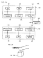
- FIG. 2A illustrates a block diagram for describing a hardware structure of a biometric authentication device 400 in accordance with a first embodiment.
- the biometric authentication device 400 has a structure in which a terminal 100, a terminal 200 and a storage device 300 are coupled with each other via a network.
- a communication network such as an intranet, a public line network or internet may be used as the network.
- the terminal 100 is a device to determine allowing of entering an office.
- the terminal 100 is a PC terminal provided in the office.
- the terminal 100 has a CPU 101, a RAM 102, a storage device 103, a first biometric sensor 104, a display device 105, a communication device 106 and so on. These components are coupled with each other via a bus or the like.
- the terminal 200 has a CPU 201, a RAM 202, a storage device 203, a second biometric sensor 204, a display device 205, a communication device 206 and so on. These components are coupled with each other via a bus or the like.
- the CPUs (Central Processing Unit) 101 and 201 are central processing units.
- the CPUs 101 and 201 include one or more core.
- the RAM (Random Access Memory) 102 is a volatile memory temporally storing a program executed by the CPU 101, a data processed by the CPU 101, and so on.
- the RAM 202 is a volatile memory temporally storing a program executed by the CPU 201, a data processed by the CPU 201, and so on.
- the storage devices 103 and 203 are nonvolatile memory devices.
- the storage devices 103 and 203 may be SSDs (Solid State Drive) such as ROMs (Read Only Memory) or flash memories, or hard disks driven by hard disk drives.
- the display device 105 is a device for showing a result of each process of the terminal 100.
- the display device 205 is a device for showing a result of each process of the terminal 200.
- the display devices 105 and 205 are liquid crystal displays or the like.
- the communication devices 106 and 206 are interfaces for transmitting and receiving a signal with an outer component.
- the first biometric sensor 104 and the second biometric sensor 204 are sensors to obtain biometric information of a user.
- the biometric information of a user is not limited, and is information of a biometric body such as a fingerprint, a vein, an iris, a voiceprint or a shape.
- a sensor to detect an image of a palm vein is used as the first biometric sensor 104 and the second biometric sensor 204, as an example.
- FIG. 2B illustrates a schematic view for describing the first biometric sensor 104 to detect a palm vein.
- the first biometric sensor 104 is an imaging device to take an image of a vein under a palm skin with use of a near-infrared ray having high permeability with respect to a human body.
- the first biometric sensor 104 has a CMOS (Complementary Metal Oxide Semiconductor) camera or the like.
- An illumination to radiate a light including a near-infrared ray may be provided.
- the second biometric sensor 204 has the same structure as the first biometric sensor 104.
- the first biometric sensor 104 has higher reproducibility than the second biometric sensor 204 with respect to obtaining biometric information of a user. That is, a similarity among biometric information obtained by the first biometric sensor 104 two or more times is higher than a similarity among biometric information obtained by the second biometric sensor 204 two or more times.
- the first biometric sensor 104 and the second biometric sensor 204 are sensors to obtain a biometric image
- the first biometric sensor 104 has a device structure to achieve higher image quality than the second biometric sensor 204.
- image quality satisfying the following requirements is referred to as high image quality.
- Image quality not satisfying the following requirements is referred to as low image quality.
- image quality having less noise may be referred to as high image quality.
- F value that is an index indicating brightness may be used as the performance of a lens.
- Image quality of which limb darkening is small may be referred to as high image quality. This is because when the limb darkening is small, feature of an edge of a taken image can be extracted stably. And, authentication accuracy is improved because cut-out process of a portion for authentication is stabilized.
- the cut-out process is, for example, a process of cutting out a palm region that is an authentication object from an image.
- the limb darkening is determined by characteristic of a lens, evenness of illuminations and so on.
- Image quality of which resolution is high may be referred to as high image quality. This is because when a resolution of an image is high, an image of a fine feature can be taken and the authentication accuracy is improved.
- Resolution of an image is determined by a performance of an imaging element (CMOS or CCD), a performance of transmission path (for example, forwarding performance of USB) and so on. With respect to the performance of transmission path, this is because when capacity of a transmission path is small, it is difficult to actually use the transmission path because a high resolution data generally has a large data capacity even if the high resolution data can be obtained with use of an imaging element.
- CMOS or CCD imaging element
- transmission path for example, forwarding performance of USB
- Image quality having high resolving power may be referred to as high image quality.
- the resolving power is an index indicating distinguishability of small information and is, for example, an index of determining whether a fine line pair is correctly identified as a line pair when an image of a white line and a black line is taken. In concrete, when the resolving power is low, the white and the black are mixed, and appear in gray.
- the resolving power is determined by a performance of a lens together with the resolution.
- the MTF Modulation Transfer Function
- the MTF Modulation Transfer Function
- a surface reflection component is a reflection component occurring at an interface between a palm and air.
- the surface reflection can be reduced when a polarization board is mounted.
- the surface reflection can be reduced by an arrangement of a light source and an illuminating method.
- the storage device 300 is a nonvolatile memory device.
- the storage device 300 may be an SSD (Solid State Drive) such as a ROM (Read Only Memory) or a flash memory, or a hard disk driven by a hard disk drive.
- a biometric authentication program is stored in the storage device 300.
- the biometric authentication program may be divided into and stored by the storage devices 103 and 203.
- the biometric authentication program stored in the storage device 300 is developed to the RAMs 102 and 202.
- the CPU 101 executes the biometric authentication program developed to the RAM 102.
- the CPU 201 executes the biometric authentication program developed to the RAM 202. Thus, each process of the terminal 100 is performed.
- FIG. 3A illustrates a block diagram of each function realized by the execution of the biometric authentication program.
- the terminal 100 acts as an overall control unit 11, an imaging process unit 12, an authentication process unit 13, a template obtain unit 14, a temporal template generation unit 15 and an image process unit 16.
- the terminal 200 acts as an overall control unit 21, an imaging process unit 22, an authentication process unit 23, a template obtain unit 24 and a template cash unit 25.
- the storage device 300 acts as an enrollment database 30.
- the overall control unit 11 controls the imaging process unit 12, the authentication process unit 13, the template obtain unit 14, the temporal template generation unit 15 and the image process unit 16.
- the imaging process unit 12 obtains a palm image from the first biometric sensor 104 in accordance with an instruction of the overall control unit 11.
- the authentication process unit 13 extracts palm vein information from the palm image obtained by the imaging process unit 12 as an authentication feature in accordance with an instruction of the overall control unit 11, and performs an authentication process.
- the template obtain unit 14 obtains an enrolled template (enrolled data) from the enrollment database 30 for authentication of the authentication process unit 13.
- the temporal template generation unit 15 generates a temporal template from the authentication feature extracted by the authentication process unit 13.
- the image process unit 16 processes the image obtained by the imaging process unit 12.
- the overall control unit 21 controls the imaging process unit 22, the authentication process unit 23, the template obtain unit 24 and the template cash unit 25.
- the imaging process unit 22 obtains a palm image from the second biometric sensor 204 in accordance with an instruction of the overall control unit 21.
- the authentication process unit 23 extracts palm vein information from the palm image obtained by the imaging process unit 22 as an authentication feature in accordance with an instruction of the overall control unit 21, and performs an authentication process.
- the template obtain unit 24 obtains an enrolled template (enrolled data) from the enrollment database 30 for authentication of the authentication process unit 23.
- the template cash unit 25 temporarily stores a temporal template generated by the temporal template generation unit 15.
- FIG. 3B illustrates a table example showing an enrolled template enrolled in the enrollment database 30.
- the enrolled template includes an authentication feature related to an ID of each user.
- the enrolled template may be enrolled in the enrollment database 30 in advance with use of the first biometric sensor 104. A description will be given of details of the authentication process.
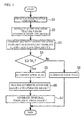
- FIG. 4 illustrates an example of a flowchart executed during the authentication process with use of the first biometric sensor 104.
- the authentication process is executed during entering an office.
- the imaging process unit 12 obtains an authentication-use palm image I from the first biometric sensor 104 (Step S1).
- the authentication process unit 13 extracts an authentication feature F from the palm image I (Step S2).
- the authentication process unit 13 compares between the authentication feature F and an enrolled template TR which the template obtain unit 14 obtains from the enrollment database 30, and calculates a similarity S of the both (Step S3).
- the authentication process unit 13 calculates a similarity between enrolled templates (TR1 to TRN) of each user and the authentication feature F.
- the authentication process unit 13 determines whether a similarity S of one of users is equal to or more than a threshold TH0 (Step S4). When it is determined as "Yes” in the Step S4, the authentication process unit 13 outputs a signal indicating that the authentication is successful (Step S5). Thus, for example, a door for entering the office is opened. Next, the image process unit 16 generates an image I' having lower image quality than the image I by processing the palm image I allowing the success of the authentication (Step S6).
- the image process unit 16 may add a noise to an image obtained by the first biometric sensor 104 in order to reduce a difference between image quality of the image obtained by the first biometric sensor 104 and image quality of an image obtained by the second biometric sensor 204.
- the image process unit 16 measures an amount ⁇ of a noise indicating a difference between the sensors in advance, and adds a random noise determined based on the ⁇ to pixels of the palm image I.
- the image process unit 16 obtains an image I' in accordance with the following formula (1).
- I'(x) is the image I' after the process.
- I(x) is the palm image I before the process.
- I ⁇ x I x + N x
- FIG. 5 illustrates another example of the generation of the image I' having low image quality.
- a sensor area is small. Therefore, there may be a case where a radiation area of a light source is limited. When the sensor area is small, it is difficult to evenly radiate a light to a subject such as a palm. In this case, when limb darkening is added to an image obtained by the first biometric sensor 104, a difference between image quality of the image obtained by the first biometric sensor 104 and image quality of an image obtained by the second biometric sensor 204 can be reduced. For example, with reference to FIG.
- the image process unit 16 obtains a limb darkening conversion curve indicating a difference between distribution of luminance values of the image obtained by the first biometric sensor 104 and distribution of luminance values of the image obtained by the second biometric sensor 204 in advance. Further, the image process unit 16 generates the image I' having low image quality by applying the limb darkening curve to the image obtained by the first biometric sensor 104. Thus, the difference between the image quality of the image obtained by the first biometric sensor 104 and the image quality of the image obtained by the second biometric sensor 204 is reduced.
- the image process unit 16 obtains the image I' in accordance with the following formula (2).
- I'(x) is the image I' after the process. I(x) is the palm image I before the process.
- FIG. 6 illustrates another example of the generation of the image I' having low image quality.
- an inexpensive sensor is used as the second biometric sensor 204
- the number of lenses the thickness of the lenses are limited.
- Optical characteristic is degraded according to a material of the lenses.
- a sharpness degree (frequency) of the image obtained by the second biometric sensor 204 is degraded.
- the sharpness degree can be expressed with use of MTF value.
- the MTF value is a value in which degradation degree of an original image caused by a lens is expressed by a frequency region.
- the image process unit 16 obtains a "frequency degradation curve" matching frequency characteristics of sensors in advance, and changes the frequency characteristics in accordance with the frequency degradation curve.
- the image process unit 16 obtains the image I' in accordance with the following formula (3).
- F'(f) is Fourier transform of the image I' after the process.
- F(f) is Fourier transform of the palm image I before the process.
- a(f) is the frequency degradation curve.
- F ⁇ f a f • F f
- a distortion of a lens may be used as an image process for reducing the difference between lenses.
- the image process unit 16 adds a lens distortion to the palm image I obtained by the first biometric sensor 104, the difference between the image quality of the image obtained by the first biometric sensor 104 and the image quality of the image obtained by the second biometric sensor 204 can be reduced.
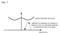
- FIG. 7 illustrates another example of the generation of the image I' having low image quality.
- a high frequency noise is added to a region of the palm image obtained by the second biometric sensor 204 in which luminance values are high
- the difference between the image quality of the image obtained by the first biometric sensor 104 and the image quality of the image obtained by the second biometric sensor 204 can be reduced.
- Surface reflection is likely to occur in a convex region of a palm with reference to FIG. 7 because an incident angle is equal to a reflection angle.
- an average luminance value is high. It is therefore possible to predict the occurrence of the surface reflection with use of the luminance value as a reference.
- a noise of high frequency occurs because of wrinkles of a surface. Therefore, the image process unit 16 may perform a process of adding a high frequency noise to the region.
- the authentication process unit 13 extracts an authentication feature from the image I', and the temporal template generation unit 15 transmits the authentication feature to the template cash unit 25 as a temporal template TI' (Step S7).
- the authentication process unit 13 outputs a signal indicating that the authentication is failed (Step S8). After the Step S7 or the Step S8, the flowchart of FIG. 4 is terminated.
- FIG. 8 illustrates an example of a flowchart executed during an authentication process with use of the second biometric sensor 204.
- the authentication process is performed after the authentication with use of the first biometric sensor 104 is successful, and is, for example, performed during a BIOS authentication at a PC starting, a log-on authentication of an OS, or the like after entering an office.
- the imaging process unit 22 obtains an authentication-use palm image I from the second biometric sensor 204 (Step S11).
- the authentication process unit 23 extracts an authentication feature F from the palm image I (Step S12).
- the authentication process unit 23 compares between the authentication feature F and an enrolled templates T R which the template obtain unit 24 obtains from the enrollment database 30, and calculates a similarity S of the both (Step S 13).
- the authentication process unit 23 determines whether the similarity S is equal to or more than a threshold TH 1 (Step S14). When it is determined as "No” in the Step S 14, the authentication process unit 23 determines whether the similarity S is equal to or more than a threshold TH 2 ( ⁇ TH 1 ) (Step S 15). When it is determined as "Yes” in the Step S 15, the template obtain unit 24 obtains a temporal template T I' from the template cash unit 5 (Step S16).
- the authentication process unit 23 compares the authentication feature F and the temporal template T I' and calculates a similarity S' of the both (Step S17).
- the authentication process unit 23 determines whether the similarity S' is equal to or more than a threshold TH 3 (Step S18).
- the authentication process unit 23 outputs a signal indicating that the authentication is successful (Step S 19).
- the authentication process unit 23 outputs a signal indicating that the authentication is failed (Step S20).
- biometric information allowing successful of an authentication obtained by the first biometric sensor 104 of which reproducibility is high during an authentication based on biometric information obtained by the second biometric sensor 204 of which reproducibility is low. Therefore, biometric information having high reliability can be used. Accordingly, it is possible to suppress degradation of authentication accuracy with use of the second biometric sensor 204. And, degradation of convenience may be suppressed. High reproducibility is not required for the second biometric sensor 204 because the biometric information having high reliability can be used. Therefore, an inexpensive device can be used as the second biometric sensor 204. And, the cost can be suppressed.
- a factor of a failure of an authentication by the second biometric sensor 204 it is possible to estimate a factor of a failure of an authentication by the second biometric sensor 204.
- a factor of the failure of authentication can be estimated.
- time passes from the enrollment of the enrolled template T R in the enrollment database 30 to an actual authentication process In this case, (1) changing of biometric body itself, (2) changing unique to a comparing such as changing of a posture or a noise, and so on are factors of the failure of authentication. Influence of a wound of a surface or the like may be a factor of (1).
- the factor of (1) is hardly included in a high image quality image obtained on the day. Therefore, it is possible to predict a factor of a failure of authentication by comparing a high image quality image obtained by the first biometric sensor 104 on the day (or in a very short time interval) and an image obtained by the second biometric sensor 204.
- FIG. 9 illustrates an example of a process flow for estimating a factor of a failure of authentication.
- the imaging process unit 22 obtains an authentication-use palm image I from the second biometric sensor 204 (Step S21).
- the authentication process unit 23 compares the authentication feature F extracted from the palm image I and an enrolled template T R which the template obtain unit 24 obtains from the enrollment database 30 and calculates a similarity S 0 of the both (Step S22).
- the authentication process unit 23 determines whether the similarity S 0 is equal to or more than the threshold TH 0 (Step S23). When it is determined as "Yes” in the Step S23, the authentication process unit 23 outputs a signal indicating that the authentication is successful (Step S24). When it is determined as "No” in the Step S23, the template obtain unit 24 obtains a temporal template TI' from the template cash unit 25 (Step S25).
- the authentication process unit 23 compares between the authentication feature F and the temporal template T I' and calculates a similarity S T of the both (Step S26).
- the authentication process unit 23 determines whether the similarity S T is equal to or more than a threshold TH T (Step S27).
- the authentication process unit 23 estimates that a changing of a biometric body is an error factor and makes the display device 205 show the estimation (Step S28).
- the authentication process unit 23 estimates that a posture of the biometric body or the like during the authentication is the failure of authentication and makes the display device 205 show the estimation (Step S29).
- a comparing between the authentication feature F and the temporal template T I' is performed.
- similarity of this case is high, it is estimated that a changing occurs in a biometric feature, because although similarity between the temporal template T I' and the authentication feature F is high, similarity between an enrolled template enrolled previously and the authentication feature F is low.
- a correct determination can be performed by performing an image process for reducing the difference between image qualities of sensors.
- the structure in which a temporal template is generated with respect to all users is described.
- the structure is not limited.
- the generation of the temporal templates may be valid or invalid with respect to each user.
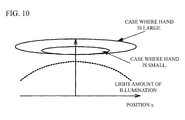
- the limb darkening has large influence on a person having a large hand but the limb darkening has little influence on a person having a small hand. Therefore, when the generation of the temporal template is suppressed with respect to the user having a small hand, the imaging process achieves an effect of reducing CPU burden, reducing power consumption and reducing storage capacity.
- Influence degree of surface reflection differs with respect to an individual. This is because a shape of a palm differs with respect to an individual although the surface reflection is largely subjected to influence of an incident angle and a reflection angle of a light. Therefore, there is a user that is largely subjected to influence of the surface reflection and a user that is not largely subjected to the influence of the surface reflection.
- a process of adding surface reflection is applied to a specific user who is largely subjected to the surface reflection, the above-mentioned effect is achieved.
- the surface reflection it is difficult to determine with or without applying during enrollment, being different from a size of a hand. This is because, the influence of the surface reflection depends on a holding condition of a palm and it is difficult to determine only from image data of few times during an enrolling. And so, with or without applying may be determined according to a history of the authentication result. That is, a rate of a failure of authentication for a given time or a given times may be searched. When the rate of the failure of authentication is more than a predetermined value, image quality of an image of a case where an authentication with use of the biometric sensor 104 is successful may be degraded and a temporal template may be generated.
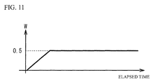
- a fusion score (total similarity) in which a similarity S R between an authentication feature F extracted from an image I obtained by the second biometric sensor 204 and an enrolled template T R and a similarity S T between the authentication feature F and the temporal template T I' are combined may be used.
- a total similarity S TOTAL may be calculated in accordance with the following formula (4).
- S TOTAL 1.0 - w ⁇ S R + wS T
- "w” is a coefficient indicating a weight of each similarity. Just after enrollment of an enrolled template T R , a difference between the enrolled template T R and the temporal template T I' is small. On the other hand, as time passes, the difference between the enrolled template T R and the temporal template T I' gets larger. Therefore, "w” may be small just after the enrollment, and “w” may be enlarged as time passes. In the example of FIG. 11 , an upper limit value (0.5) is set in the "w".
- the number of type of a biometric sensor having low reproducibility is not always one.
- a plurality of biometric sensors having low image quality are provided.
- a biometric sensor 204a and a biometric sensor 204b are provided.
- a plurality of factors are mixed as a degradation factor of image quality.
- reduction of MTF is a degradation factor of the biometric sensor 204a
- reduction of MTF and a noise are two degradation factors of the second biometric sensor 204b. This may occur when although the biometric sensors 204a and 204b use a common lens, the biometric sensors 204a and 204b have a different imaging element.
- temporal template T I' when the temporal template T I' is generated from an image obtained by the first biometric sensor 104, processes may be streamlined by sequentially applying the processes.
- a temporal template T1 in which a MTF degradation process is applied may be generated, and the temporal template T1 may be used in an authentication with use of the biometric sensor 204a.
- a temporal template T2 in which a noise adding process is applied to the temporal template T1 may be generated, and the temporal template T2 may be used in an authentication with use of the biometric sensor 204b. In this manner, it is possible to streamline the processes more than generating each image for each sensor.
- an authentication server may perform the authentication process.
- a high image quality sensor is used for entrance to a country
- a low image quality sensor is used for identity check after the entrance to the country.
- the authentication server solely performs the authentication process.
- FIG. 12 illustrates a block diagram for describing a hardware structure of a biometric authentication device 400a in accordance with a second embodiment.
- the biometric authentication device 400a has a structure in which a terminal 100a, a terminal 200a, the storage device 300 and a server 500 are coupled with each other via a network.
- the terminal 100a is, for example, a device performing an authentication of entrance to a country.
- the terminal 200a is, for example, a terminal used for identity check after entrance to the country.
- the server 500 is a sole authentication server that performs authentication processes.
- the terminal 100a has the CPU 101, the RAM 102, the storage device 103, the first biometric sensor 104, the display device 105, the communication device 106 and so on. These components are coupled with each other via a bus or the like.
- the terminal 200a has the CPU 201, the RAM 202, the storage device 203, the second biometric sensor 204, the display device 205, the communication device 206 and so on. These components are coupled with each other via a bus or the like.
- the server 500 has a CPU 501, a RAM 502, a storage device 503, a communication device 504 and so on. These components are coupled with each other via a bus or the like.
- the CPU 501 is a central processing unit.
- the RAM 502 is a volatile memory temporally storing a program executed by the CPU 501, a data processed by the CPU 501, and so on.
- the storage device 503 is a nonvolatile memory device.
- the communication devices 504 is an interface for transmitting and receiving a signal with an outer component.
- the storage device 300 is a nonvolatile memory device and stores the biometric authentication program.
- the biometric authentication program may be divided into and stored by the storage devices 103. 203 and 503.
- the biometric authentication program stored in the storage device 300 is developed to the RAMs 102. 202 and 502.
- the CPU 101 executes the biometric authentication program developed to the RAM 102.
- the CPU 201 executes the biometric authentication program developed to the RAM 202.
- the CPU 501 executes the biometric authentication program developed to the RAM 502. Thus, each process of the biometric authentication device 400a is performed.
- FIG. 13 illustrates a block diagram of each function realized by the execution of the biometric authentication program.
- the terminal 100a acts as the overall control unit 11, the imaging process unit 12, the authentication process unit 13, the temporal template generation unit 15 and the image process unit 16.
- the terminal 200a acts as the overall control unit 21, the imaging process unit 22 and the authentication process unit 23.
- the storage device 300 acts as the enrollment database 30.
- the server 500 acts as an overall control unit 31, an authentication process unit 32, a template obtain unit 33 and a template cash unit 34.
- the authentication process unit 13 extracts an authentication feature from a palm image obtained by the biometric sensor 104, and transmits the biometric authentication feature to the server 500 without performing an authentication process.
- the authentication process unit 23 extracts an authentication feature from a palm image obtained by the second biometric sensor 204 and transmits the authentication feature to the server 500 without performing an authentication process.
- the overall control unit 31 controls the authentication process unit 32, the template obtain unit 33 and the template cash unit 34.
- the authentication process unit 32 performs an authentication process with use of the authentication features transmitted from the authentication process unit 13 and the authentication process unit 23 in accordance with an instruction of the overall control unit 31.
- the template obtain unit 33 obtains a template from the enrollment database 30 for an authentication of the authentication process unit 32.
- the template cash unit 34 temporarily stores a template generated by the temporal template generation unit 15.
- FIG. 14 illustrates an example of a flowchart executed during an authentication process with use of the biometric sensor 104.
- the authentication process is performed during entrance to a country or the like.
- the imaging process unit 12 obtains an authentication-use palm image I from the biometric sensor 104 (Step S31).
- the authentication process unit 13 extracts an authentication feature F from the palm image I (Step S32).
- the authentication process unit 13 transmits the authentication feature F to the server 500 (Step S33).
- the authentication process unit 32 compares between the authentication feature F and an enrolled template T R which the template obtain unit 33 obtains from the enrollment database 30, and calculates a similarity S of the both (Step S34). Next, the authentication process unit 32 determines whether the similarity S is equal to or more than the threshold TH 0 (Step S35). When it is determined as "Yes” in the Step S35, the authentication process unit 32 outputs a signal indicating that the authentication is successful (Step S36). When it is determined as "No” in the Step S35, the authentication process unit 32 outputs a signal indicating that the authentication is failed (Step S37).
- the authentication process unit 13 receives the authentication result from the authentication process unit 32 (Step S38). The authentication process unit 13 determines whether the received authentication result indicates successful (Step S39). When it is determined as "Yes” in the Step S39, the authentication process unit 13 outputs a signal indicating that the authentication is successful (Step S40). Next, the image process unit 16 processes the palm image I and generates an image I' of which image quality is lower than the image I (Step S41). Next, the authentication process unit 13 extracts an authentication feature from the image I', and the temporal template generation unit 15 transmits the authentication feature to the server 500 as a temporal template T I' (Step S42). When it is determined as "No” in the Step S39, the authentication process unit 13 outputs a signal indicating that the authentication is failed (Step S43). After the Step S42 or the Step S43, the flowchart of FIG. 14 is terminated.
- FIG. 15 illustrates an example of a flowchart executed during an authentication process with use of the second biometric sensor 204.
- the authentication process is performed after the authentication process with use of the first biometric sensor 104 is successful, and is, for example, performed during an identity check after the entrance to the country.
- the imaging process unit 22 obtains an authentication-use palm image I from the second biometric sensor 204 (Step S51).
- the authentication process unit 23 extracts an authentication feature F from the palm image I (Step S52).
- the authentication process unit 23 transmits the authentication feature F to the server 500 (Step S53).
- the authentication process unit 23 receives an authentication result from the server 500 (Step S54).
- the authentication process unit 23 determines whether the received authentication result is successful (Step S55). When it is determined as “Yes” in the Step S25, the authentication process unit 23 outputs a signal indicating that the authentication is successful (Step S56). When it is determined as "No” in the Step S55, the authentication process unit 23 outputs a signal indicating that the authentication is failed (Step S57). After the Step S56 or the Step S57, the flowchart of FIG. 15 is terminated.
- FIG. 16 illustrates an example of a flowchart executed by the server 500 after the Step S53 of FIG. 15 .
- the authentication process unit 32 receives an authentication feature F from the authentication process unit 23 (Step S61).
- the authentication process unit 32 compares between the authentication feature F and an enrolled template T R which the template obtain unit 33 obtains from the enrollment database 30, and calculates a similarity of the both (Step S62).
- the authentication process unit 32 determines whether the similarity S is equal to or more than a threshold TH 1 (Step S63). When it is determined as "No” in the Step S63, the authentication process unit 32 determines whether the similarity S is equal to or more than a threshold TH 2 ( ⁇ TH 1 ) (Step S64). When it is determined as "Yes” in the Step S64, the template obtain unit 33 obtains a temporal template T I' from the template cash unit 34 (Step S65).
- the authentication process unit compares the authentication feature F and the temporal template T I' and calculates a similarity S' of the both (Step S66).
- the authentication process unit 32 determines whether the similarity S' is equal to or more than a threshold TH 3 (Step S67). When it is determined as "Yes” in the Step S67 or it is determined as “Yes” in the Step S64, the authentication process unit 32 returns a signal indicating that the authentication is successful to the terminal 200a (Step S68). When it is determined as "No” in the Step S64 or when it is determined as "No” in the Step S67, the authentication process unit 32 returns a signal indicating that the authentication is failed to the terminal 200a (Step S69). After the Step S19 or the Step S20, the execution of the flowchart of FIG. 15 is terminated.
- biometric information allowing successful of an authentication obtained by the first biometric sensor 104 of which reproducibility is high during an authentication based on biometric information obtained by the second biometric sensor 204 of which reproducibility is low. Therefore, biometric information having high reliability can be used. Accordingly, it is possible to suppress degradation of authentication accuracy with use of the second biometric sensor 204. And, degradation of convenience may be suppressed. High reproducibility is not required for the second biometric sensor 204 because the biometric information having high reliability can be used. Therefore, an inexpensive device can be used as the second biometric sensor 204. And, the cost can be suppressed.
Landscapes
- Engineering & Computer Science (AREA)
- Physics & Mathematics (AREA)
- General Physics & Mathematics (AREA)
- Multimedia (AREA)
- Theoretical Computer Science (AREA)
- Human Computer Interaction (AREA)
- Quality & Reliability (AREA)
- Collating Specific Patterns (AREA)
- Measurement Of The Respiration, Hearing Ability, Form, And Blood Characteristics Of Living Organisms (AREA)
Abstract
Description
- The present invention relates to a biometric authentication device, a biometric authentication method and a biometric authentication program.
- A biometric authentication is performed by comparing a comparison-use data obtained by a biometric sensor and an enrolled data enrolled in a database. Recently, the biometric authentication is diversified.
Patent Documents 1 to 3 disclose a technology of the diversified biometric authentications. -
- Patent Document 1: Japanese Laid-open Patent Publication No.
2001-14462 - Patent Document 2: Japanese Laid-open Patent Publication No.
2006-107340 - Patent Document 3: Japanese Laid-open Patent Publication No.
2009-169796 - However, with the technology of
Patent Documents 1 to 3, authentication accuracy may be degraded when a plurality of biometric sensors are used. - In view of the above described problem, it is an object to provide a biometric authentication device, a biometric authentication method and a biometric authentication program that can suppress authentication degradation when a plurality of biometric sensors are used.
- In order to achieve the above-mentioned object, a biometric authentication device disclosed in the specification includes: a first biometric sensor that obtains biometric information of a user; a second biometric sensor that obtains biometric information of a user at a lower degree of reproducibility than the first biometric sensor; an authentication process unit that performs an authentication by comparing with use of the biometric information obtained by the first biometric sensor and the second biometric sensor, wherein the authentication process unit compares biometric information obtained by the second biometric sensor with use of biometric information obtained by the first biometric sensor of a case where a comparing between the biometric information obtained by the first biometric sensor and enrolled information is successful.
- In order to achieve the above-mentioned object, a biometric authentication method disclosed in the specification includes: performing an authentication by comparing biometric information obtained by a first biometric sensor that obtains biometric information of a user and an enrolled information; and with use of the biometric information of a case where the comparing is successful, performing an authentication by comparing biometric information obtained by a second biometric sensor that obtains biometric information of a user at a lower degree of reproducibility than the first biometric sensor.
- In order to achieve the above-mentioned object, a program disclosed in the specification is for causing a computer to execute a process including: performing an authentication by comparing biometric information obtained by a first biometric sensor that obtains biometric information of a user and an enrolled information; and with use of the biometric information of a case where the comparing is successful, performing an authentication by comparing biometric information obtained by a second biometric sensor that obtains biometric information of a user at a lower degree of reproducibility than the first biometric sensor.
- A biometric authentication device, a biometric authentication method and a biometric authentication program disclosed in the specification can suppress degradation of authentication accuracy when a plurality of biometric sensors are used.
-
-
FIG. 1 is a drawing for describing a situation example where embodiments are applied; -
FIG. 2A illustrates a block diagram for describing a hardware structure of a biometric authentication device in accordance with a first embodiment; -
FIG. 2B illustrates a schematic view for describing an example of a biometric sensor to detect a palm vein; -
FIG. 3A illustrates a block diagram of each function realized by an execution of a biometric authentication program; -
FIG. 3B illustrates a table example showing an enrolled template enrolled in an enrollment database; -
FIG. 4 illustrates an example of a flowchart executed during an authentication process with use of at biometric sensor; -
FIG. 5 illustrates an example of generation of an image having low image quality. -
FIG. 6 illustrates another example of generation of an image having low image quality; -
FIG. 7 illustrates another example of generation of an image having low image quality; -
FIG. 8 illustrates an example of a flowchart executed during an authentication process with use of a biometric sensor; -
FIG. 9 illustrates an example of a process flow for estimating a factor of a failure of an authentication; -
FIG. 10 illustrates influence of hand size on limb darkening. -
FIG. 11 illustrates a fusion score; -
FIG. 12 illustrates a block diagram for describing a hardware structure of a biometric authentication device in accordance with a second embodiment; -
FIG. 13 illustrates a block diagram of each function realized by an execution of a biometric authentication program; -
FIG. 14 illustrates an example of a flowchart executed during an authentication process with use of a biometric sensor; -
FIG. 15 illustrates an example of a flowchart executed during an authentication process with use of a second biometric sensor; and -
FIG. 16 illustrates an example of a flowchart executed by a server after a Step S53 ofFIG. 15 . - A description will be given of a situation example where the following embodiments are applied, before describing the embodiments.
FIG. 1 is a drawing for describing the situation example where the following embodiments are applied. With reference toFIG. 1 , a sensor for administration of entering or leaving a room (type A sensor) and a sensor for administration of log-on of a PC in an office, administration of door lock or the like (type B sensor) are provided. A biometric authentication is performed by comparing biometric information obtained by a biometric sensor and enrolled information enrolled in an enrollment database. - The administration of entering or leaving a room is a first stage of a security. Therefore, high accuracy authentication is required for the type A sensor. And so, a sensor that has high authentication accuracy and high resistance against outer light but is large and expensive is used as the type A sensor. On the other hand, a sensor used in each desktop PC or note PC in an office has a limit in size. The number of the PCs is large. Therefore, cost cut is required. And so, a small and inexpensive sensor is used as the type B sensor. In this case, authentication accuracy in the office is degraded. It is demanded that the authentication accuracy of the type B sensor is improved. And so, in the following embodiments, a description will be given of a biometric authentication device, a biometric authentication method and a biometric authentication program that are capable of suppressing degradation of authentication accuracy in a case where a plurality of sensors are used.
-
FIG. 2A illustrates a block diagram for describing a hardware structure of abiometric authentication device 400 in accordance with a first embodiment. With reference toFIG. 2A , thebiometric authentication device 400 has a structure in which aterminal 100, aterminal 200 and astorage device 300 are coupled with each other via a network. A communication network such as an intranet, a public line network or internet may be used as the network. For example, theterminal 100 is a device to determine allowing of entering an office. Theterminal 100 is a PC terminal provided in the office. - The terminal 100 has a
CPU 101, aRAM 102, astorage device 103, a firstbiometric sensor 104, adisplay device 105, acommunication device 106 and so on. These components are coupled with each other via a bus or the like. The terminal 200 has aCPU 201, aRAM 202, astorage device 203, a secondbiometric sensor 204, adisplay device 205, acommunication device 206 and so on. These components are coupled with each other via a bus or the like. - The CPUs (Central Processing Unit) 101 and 201 are central processing units. The
CPUs CPU 101, a data processed by theCPU 101, and so on. TheRAM 202 is a volatile memory temporally storing a program executed by theCPU 201, a data processed by theCPU 201, and so on. - The
storage devices storage devices display device 105 is a device for showing a result of each process of the terminal 100. Thedisplay device 205 is a device for showing a result of each process of the terminal 200. Thedisplay devices communication devices - The first
biometric sensor 104 and the secondbiometric sensor 204 are sensors to obtain biometric information of a user. The biometric information of a user is not limited, and is information of a biometric body such as a fingerprint, a vein, an iris, a voiceprint or a shape. In the embodiment, a sensor to detect an image of a palm vein is used as the firstbiometric sensor 104 and the secondbiometric sensor 204, as an example.FIG. 2B illustrates a schematic view for describing the firstbiometric sensor 104 to detect a palm vein. - The first
biometric sensor 104 is an imaging device to take an image of a vein under a palm skin with use of a near-infrared ray having high permeability with respect to a human body. The firstbiometric sensor 104 has a CMOS (Complementary Metal Oxide Semiconductor) camera or the like. An illumination to radiate a light including a near-infrared ray may be provided. The secondbiometric sensor 204 has the same structure as the firstbiometric sensor 104. - The first
biometric sensor 104 has higher reproducibility than the secondbiometric sensor 204 with respect to obtaining biometric information of a user. That is, a similarity among biometric information obtained by the firstbiometric sensor 104 two or more times is higher than a similarity among biometric information obtained by the secondbiometric sensor 204 two or more times. When the firstbiometric sensor 104 and the secondbiometric sensor 204 are sensors to obtain a biometric image, the firstbiometric sensor 104 has a device structure to achieve higher image quality than the secondbiometric sensor 204. - A description will be given of high image quality and low image quality. In the embodiment, image quality satisfying the following requirements is referred to as high image quality. Image quality not satisfying the following requirements is referred to as low image quality. In concrete, image quality having less noise may be referred to as high image quality. When there is less noise, it is possible to stably extract an authentication feature and authentication accuracy gets higher. A noise of an image is determined by light amount of a light source or performance of a lens. For example, when the light amount is large, the noise decreases. F value that is an index indicating brightness may be used as the performance of a lens.
- Image quality of which limb darkening is small may be referred to as high image quality. This is because when the limb darkening is small, feature of an edge of a taken image can be extracted stably. And, authentication accuracy is improved because cut-out process of a portion for authentication is stabilized. The cut-out process is, for example, a process of cutting out a palm region that is an authentication object from an image. The limb darkening is determined by characteristic of a lens, evenness of illuminations and so on.
- Image quality of which resolution is high may be referred to as high image quality. This is because when a resolution of an image is high, an image of a fine feature can be taken and the authentication accuracy is improved. Resolution of an image is determined by a performance of an imaging element (CMOS or CCD), a performance of transmission path (for example, forwarding performance of USB) and so on. With respect to the performance of transmission path, this is because when capacity of a transmission path is small, it is difficult to actually use the transmission path because a high resolution data generally has a large data capacity even if the high resolution data can be obtained with use of an imaging element.
- Image quality having high resolving power may be referred to as high image quality. The resolving power is an index indicating distinguishability of small information and is, for example, an index of determining whether a fine line pair is correctly identified as a line pair when an image of a white line and a black line is taken. In concrete, when the resolving power is low, the white and the black are mixed, and appear in gray. The resolving power is determined by a performance of a lens together with the resolution. The MTF (Modulation Transfer Function) may be used as the index of the resolving power.
- Image quality having less surface reflection may be referred to as high image quality. This is because when an amount of the surface reflection is small, it is possible to clearly take an image of a vein image that is an inner feature and the authentication accuracy is improved. A surface reflection component is a reflection component occurring at an interface between a palm and air. The surface reflection can be reduced when a polarization board is mounted. The surface reflection can be reduced by an arrangement of a light source and an illuminating method.
- The
storage device 300 is a nonvolatile memory device. Thestorage device 300 may be an SSD (Solid State Drive) such as a ROM (Read Only Memory) or a flash memory, or a hard disk driven by a hard disk drive. A biometric authentication program is stored in thestorage device 300. The biometric authentication program may be divided into and stored by thestorage devices - Next, a description will be given of each process of the terminal 100. The biometric authentication program stored in the
storage device 300 is developed to theRAMs CPU 101 executes the biometric authentication program developed to theRAM 102. TheCPU 201 executes the biometric authentication program developed to theRAM 202. Thus, each process of the terminal 100 is performed. -
FIG. 3A illustrates a block diagram of each function realized by the execution of the biometric authentication program. With reference toFIG. 3A , by the execution of the biometric authentication program, the terminal 100 acts as anoverall control unit 11, animaging process unit 12, anauthentication process unit 13, a template obtainunit 14, a temporaltemplate generation unit 15 and animage process unit 16. By the execution of the biometric authentication program, the terminal 200 acts as anoverall control unit 21, animaging process unit 22, anauthentication process unit 23, a template obtainunit 24 and atemplate cash unit 25. And, by the execution of the biometric authentication program, thestorage device 300 acts as anenrollment database 30. - The
overall control unit 11 controls theimaging process unit 12, theauthentication process unit 13, the template obtainunit 14, the temporaltemplate generation unit 15 and theimage process unit 16. Theimaging process unit 12 obtains a palm image from the firstbiometric sensor 104 in accordance with an instruction of theoverall control unit 11. Theauthentication process unit 13 extracts palm vein information from the palm image obtained by theimaging process unit 12 as an authentication feature in accordance with an instruction of theoverall control unit 11, and performs an authentication process. The template obtainunit 14 obtains an enrolled template (enrolled data) from theenrollment database 30 for authentication of theauthentication process unit 13. The temporaltemplate generation unit 15 generates a temporal template from the authentication feature extracted by theauthentication process unit 13. Theimage process unit 16 processes the image obtained by theimaging process unit 12. - The
overall control unit 21 controls theimaging process unit 22, theauthentication process unit 23, the template obtainunit 24 and thetemplate cash unit 25. Theimaging process unit 22 obtains a palm image from the secondbiometric sensor 204 in accordance with an instruction of theoverall control unit 21. Theauthentication process unit 23 extracts palm vein information from the palm image obtained by theimaging process unit 22 as an authentication feature in accordance with an instruction of theoverall control unit 21, and performs an authentication process. The template obtainunit 24 obtains an enrolled template (enrolled data) from theenrollment database 30 for authentication of theauthentication process unit 23. Thetemplate cash unit 25 temporarily stores a temporal template generated by the temporaltemplate generation unit 15. -
FIG. 3B illustrates a table example showing an enrolled template enrolled in theenrollment database 30. With reference toFIG. 3B , the enrolled template includes an authentication feature related to an ID of each user. The enrolled template may be enrolled in theenrollment database 30 in advance with use of the firstbiometric sensor 104. A description will be given of details of the authentication process. -
FIG. 4 illustrates an example of a flowchart executed during the authentication process with use of the firstbiometric sensor 104. For example, the authentication process is executed during entering an office. Theimaging process unit 12 obtains an authentication-use palm image I from the first biometric sensor 104 (Step S1). Next, theauthentication process unit 13 extracts an authentication feature F from the palm image I (Step S2). Next, theauthentication process unit 13 compares between the authentication feature F and an enrolled template TR which the template obtainunit 14 obtains from theenrollment database 30, and calculates a similarity S of the both (Step S3). Theauthentication process unit 13 calculates a similarity between enrolled templates (TR1 to TRN) of each user and the authentication feature F. - Next, the
authentication process unit 13 determines whether a similarity S of one of users is equal to or more than a threshold TH0 (Step S4). When it is determined as "Yes" in the Step S4, theauthentication process unit 13 outputs a signal indicating that the authentication is successful (Step S5). Thus, for example, a door for entering the office is opened. Next, theimage process unit 16 generates an image I' having lower image quality than the image I by processing the palm image I allowing the success of the authentication (Step S6). - Here, a description will be given of an example of the generation of the image I' having low image quality. For example, when the second
biometric sensor 204 of which reproducibility is low is used, there may be case where a sufficient illumination amount is not achieved. For example, when the secondbiometric sensor 204 is built in the note PC, it is necessary to reduce light amount in view of power consumption. As a result of the reduction of the light amount, many noises are included in an image. There may be a case where an imaging element (CCD or CMOS) used for obtaining an image is downsized. When an area of the imaging element is small, a light amount per a unit area is reduced. This results in increase of the noise. A small imaging element is often used in a small and inexpensive sensor. As a result, the noise tends to increase. - When the noise is included in the image, extraction of a feature amount (a ridge line of a fingerprint or a vein pattern) is unstable. And so, the
image process unit 16 may add a noise to an image obtained by the firstbiometric sensor 104 in order to reduce a difference between image quality of the image obtained by the firstbiometric sensor 104 and image quality of an image obtained by the secondbiometric sensor 204. For example, theimage process unit 16 measures an amount σ of a noise indicating a difference between the sensors in advance, and adds a random noise determined based on the σ to pixels of the palm image I. In concrete, theimage process unit 16 obtains an image I' in accordance with the following formula (1). In the following formula (1), I'(x) is the image I' after the process. I(x) is the palm image I before the process. N(x) is a noise (average = 0).
-
FIG. 5 illustrates another example of the generation of the image I' having low image quality. For example, when a small sensor is used as the secondbiometric sensor 204, a sensor area is small. Therefore, there may be a case where a radiation area of a light source is limited. When the sensor area is small, it is difficult to evenly radiate a light to a subject such as a palm. In this case, when limb darkening is added to an image obtained by the firstbiometric sensor 104, a difference between image quality of the image obtained by the firstbiometric sensor 104 and image quality of an image obtained by the secondbiometric sensor 204 can be reduced. For example, with reference toFIG. 5 , theimage process unit 16 obtains a limb darkening conversion curve indicating a difference between distribution of luminance values of the image obtained by the firstbiometric sensor 104 and distribution of luminance values of the image obtained by the secondbiometric sensor 204 in advance. Further, theimage process unit 16 generates the image I' having low image quality by applying the limb darkening curve to the image obtained by the firstbiometric sensor 104. Thus, the difference between the image quality of the image obtained by the firstbiometric sensor 104 and the image quality of the image obtained by the secondbiometric sensor 204 is reduced. In concrete, theimage process unit 16 obtains the image I' in accordance with the following formula (2). In the following formula (2), I'(x) is the image I' after the process. I(x) is the palm image I before the process. a(x) is a limb darkening curve (a(0) = 1.0)
-
FIG. 6 illustrates another example of the generation of the image I' having low image quality. For example, when an inexpensive sensor is used as the secondbiometric sensor 204, the number of lenses, the thickness of the lenses are limited. Optical characteristic is degraded according to a material of the lenses. In this case, a sharpness degree (frequency) of the image obtained by the secondbiometric sensor 204 is degraded. The sharpness degree can be expressed with use of MTF value. The MTF value is a value in which degradation degree of an original image caused by a lens is expressed by a frequency region. In this case, when the frequency characteristic of the image obtained by the firstbiometric sensor 104 is degraded, the difference between the image quality of the image obtained by the firstbiometric sensor 104 and the image quality of the image obtained by the secondbiometric sensor 204 can be reduced. In concrete, with reference toFIG. 6 , theimage process unit 16 obtains a "frequency degradation curve" matching frequency characteristics of sensors in advance, and changes the frequency characteristics in accordance with the frequency degradation curve. In concrete, theimage process unit 16 obtains the image I' in accordance with the following formula (3). In the following formula (3), F'(f) is Fourier transform of the image I' after the process. F(f) is Fourier transform of the palm image I before the process. a(f) is the frequency degradation curve.
- A distortion of a lens may be used as an image process for reducing the difference between lenses. In this case, when the
image process unit 16 adds a lens distortion to the palm image I obtained by the firstbiometric sensor 104, the difference between the image quality of the image obtained by the firstbiometric sensor 104 and the image quality of the image obtained by the secondbiometric sensor 204 can be reduced. -
FIG. 7 illustrates another example of the generation of the image I' having low image quality. For example, when a high frequency noise is added to a region of the palm image obtained by the secondbiometric sensor 204 in which luminance values are high, the difference between the image quality of the image obtained by the firstbiometric sensor 104 and the image quality of the image obtained by the secondbiometric sensor 204 can be reduced. Surface reflection is likely to occur in a convex region of a palm with reference toFIG. 7 because an incident angle is equal to a reflection angle. In the region, an average luminance value is high. It is therefore possible to predict the occurrence of the surface reflection with use of the luminance value as a reference. In the region with the surface reflection, a noise of high frequency occurs because of wrinkles of a surface. Therefore, theimage process unit 16 may perform a process of adding a high frequency noise to the region. - With reference to
FIG. 4 again, theauthentication process unit 13 extracts an authentication feature from the image I', and the temporaltemplate generation unit 15 transmits the authentication feature to thetemplate cash unit 25 as a temporal template TI' (Step S7). When it is determined as "No" in the Step S4, theauthentication process unit 13 outputs a signal indicating that the authentication is failed (Step S8). After the Step S7 or the Step S8, the flowchart ofFIG. 4 is terminated. -
FIG. 8 illustrates an example of a flowchart executed during an authentication process with use of the secondbiometric sensor 204. The authentication process is performed after the authentication with use of the firstbiometric sensor 104 is successful, and is, for example, performed during a BIOS authentication at a PC starting, a log-on authentication of an OS, or the like after entering an office. Theimaging process unit 22 obtains an authentication-use palm image I from the second biometric sensor 204 (Step S11). Next, theauthentication process unit 23 extracts an authentication feature F from the palm image I (Step S12). Next, theauthentication process unit 23 compares between the authentication feature F and an enrolled templates TR which the template obtainunit 24 obtains from theenrollment database 30, and calculates a similarity S of the both (Step S 13). - Next, the
authentication process unit 23 determines whether the similarity S is equal to or more than a threshold TH1 (Step S14). When it is determined as "No" in theStep S 14, theauthentication process unit 23 determines whether the similarity S is equal to or more than a threshold TH2 (<TH1) (Step S 15). When it is determined as "Yes" in theStep S 15, the template obtainunit 24 obtains a temporal template TI' from the template cash unit 5 (Step S16). - Next, the
authentication process unit 23 compares the authentication feature F and the temporal template TI' and calculates a similarity S' of the both (Step S17). Next, theauthentication process unit 23 determines whether the similarity S' is equal to or more than a threshold TH3 (Step S18). When it is determined as "Yes" in the Step S18 or it is determined as "Yes" in the Step S14, theauthentication process unit 23 outputs a signal indicating that the authentication is successful (Step S 19). When it is determined as "No" in theStep S 18 or it is determined as "No" in theStep S 15, theauthentication process unit 23 outputs a signal indicating that the authentication is failed (Step S20). After theStep S 19 or the Step S20, the execution of the flowchart ofFIG. 8 is terminated. - In the embodiment, it is possible to use biometric information allowing successful of an authentication obtained by the first
biometric sensor 104 of which reproducibility is high during an authentication based on biometric information obtained by the secondbiometric sensor 204 of which reproducibility is low. Therefore, biometric information having high reliability can be used. Accordingly, it is possible to suppress degradation of authentication accuracy with use of the secondbiometric sensor 204. And, degradation of convenience may be suppressed. High reproducibility is not required for the secondbiometric sensor 204 because the biometric information having high reliability can be used. Therefore, an inexpensive device can be used as the secondbiometric sensor 204. And, the cost can be suppressed. - When a plurality of biometric sensors are provided, there may be a case where an enrolled templates is needed for each of the biometric sensors. This is because influence on the authentication accuracy is large because a sensor having low image quality is largely subjected to influence of a slight posture changing of a subject (palm or the like). In contrast, in the embodiment, it is possible to use a temporal template based on biometric information allowing successful of the authentication. Therefore, it is not necessary to individually make an enrolled template with respect to each biometric sensor. Accordingly, an amount of the enrolled templates can be reduced.
- In the embodiment, it is possible to estimate a factor of a failure of an authentication by the second
biometric sensor 204. In concrete, when an image having high image quality obtained by the firstbiometric sensor 104 is used, a factor of the failure of authentication can be estimated. First, there may be a case where time passes from the enrollment of the enrolled template TR in theenrollment database 30 to an actual authentication process. In this case, (1) changing of biometric body itself, (2) changing unique to a comparing such as changing of a posture or a noise, and so on are factors of the failure of authentication. Influence of a wound of a surface or the like may be a factor of (1). On the other hand, the factor of (1) is hardly included in a high image quality image obtained on the day. Therefore, it is possible to predict a factor of a failure of authentication by comparing a high image quality image obtained by the firstbiometric sensor 104 on the day (or in a very short time interval) and an image obtained by the secondbiometric sensor 204. -
FIG. 9 illustrates an example of a process flow for estimating a factor of a failure of authentication. With reference toFIG. 9 , theimaging process unit 22 obtains an authentication-use palm image I from the second biometric sensor 204 (Step S21). Next, theauthentication process unit 23 compares the authentication feature F extracted from the palm image I and an enrolled template TR which the template obtainunit 24 obtains from theenrollment database 30 and calculates a similarity S0 of the both (Step S22). - Next, the
authentication process unit 23 determines whether the similarity S0 is equal to or more than the threshold TH0 (Step S23). When it is determined as "Yes" in the Step S23, theauthentication process unit 23 outputs a signal indicating that the authentication is successful (Step S24). When it is determined as "No" in the Step S23, the template obtainunit 24 obtains a temporal template TI' from the template cash unit 25 (Step S25). - Next, the
authentication process unit 23 compares between the authentication feature F and the temporal template TI' and calculates a similarity ST of the both (Step S26). Next, theauthentication process unit 23 determines whether the similarity ST is equal to or more than a threshold THT (Step S27). When it is determined as "Yes" in the Step S27, theauthentication process unit 23 estimates that a changing of a biometric body is an error factor and makes thedisplay device 205 show the estimation (Step S28). When it is determined as "No" in the Step S27, theauthentication process unit 23 estimates that a posture of the biometric body or the like during the authentication is the failure of authentication and makes thedisplay device 205 show the estimation (Step S29). - In accordance with the flowchart of
FIG. 9 , when the authentication with use of the secondbiometric sensor 204 is failed, a comparing between the authentication feature F and the temporal template TI' is performed. When similarity of this case is high, it is estimated that a changing occurs in a biometric feature, because although similarity between the temporal template TI' and the authentication feature F is high, similarity between an enrolled template enrolled previously and the authentication feature F is low. In this case, a correct determination can be performed by performing an image process for reducing the difference between image qualities of sensors. - In the above-mentioned embodiments, the structure in which a temporal template is generated with respect to all users is described. However, the structure is not limited. For example, the generation of the temporal templates may be valid or invalid with respect to each user. For example, with reference to
FIG. 10 , the limb darkening has large influence on a person having a large hand but the limb darkening has little influence on a person having a small hand. Therefore, when the generation of the temporal template is suppressed with respect to the user having a small hand, the imaging process achieves an effect of reducing CPU burden, reducing power consumption and reducing storage capacity. - Influence degree of surface reflection differs with respect to an individual. This is because a shape of a palm differs with respect to an individual although the surface reflection is largely subjected to influence of an incident angle and a reflection angle of a light. Therefore, there is a user that is largely subjected to influence of the surface reflection and a user that is not largely subjected to the influence of the surface reflection. When a process of adding surface reflection is applied to a specific user who is largely subjected to the surface reflection, the above-mentioned effect is achieved.
- In the case of the surface reflection, it is difficult to determine with or without applying during enrollment, being different from a size of a hand. This is because, the influence of the surface reflection depends on a holding condition of a palm and it is difficult to determine only from image data of few times during an enrolling. And so, with or without applying may be determined according to a history of the authentication result. That is, a rate of a failure of authentication for a given time or a given times may be searched. When the rate of the failure of authentication is more than a predetermined value, image quality of an image of a case where an authentication with use of the
biometric sensor 104 is successful may be degraded and a temporal template may be generated. - In the above-mentioned embodiments, the cases in which an image that is obtained by the first
biometric sensor 104 and is processed is used for an authentication with use of the secondbiometric sensor 204 are descried. However, the embodiments are not limited. For example, a fusion score (total similarity) in which a similarity SR between an authentication feature F extracted from an image I obtained by the secondbiometric sensor 204 and an enrolled template TR and a similarity ST between the authentication feature F and the temporal template TI' are combined may be used. For example, a total similarity STOTAL may be calculated in accordance with the following formula (4).
- In the above formula (4), "w" is a coefficient indicating a weight of each similarity. Just after enrollment of an enrolled template TR, a difference between the enrolled template TR and the temporal template TI' is small. On the other hand, as time passes, the difference between the enrolled template TR and the temporal template TI' gets larger. Therefore, "w" may be small just after the enrollment, and "w" may be enlarged as time passes. In the example of
FIG. 11 , an upper limit value (0.5) is set in the "w". - The number of type of a biometric sensor having low reproducibility is not always one. For example, there may be a case where a plurality of biometric sensors having low image quality are provided. For example, it is assumed that a biometric sensor 204a and a biometric sensor 204b are provided. In this case, a plurality of factors are mixed as a degradation factor of image quality. For example, it is possible that reduction of MTF is a degradation factor of the biometric sensor 204a, and reduction of MTF and a noise are two degradation factors of the second biometric sensor 204b. This may occur when although the biometric sensors 204a and 204b use a common lens, the biometric sensors 204a and 204b have a different imaging element.
- In this case, when the temporal template TI' is generated from an image obtained by the first
biometric sensor 104, processes may be streamlined by sequentially applying the processes. In concrete, first, a temporal template T1 in which a MTF degradation process is applied may be generated, and the temporal template T1 may be used in an authentication with use of the biometric sensor 204a. Sequentially, a temporal template T2 in which a noise adding process is applied to the temporal template T1 may be generated, and the temporal template T2 may be used in an authentication with use of the biometric sensor 204b. In this manner, it is possible to streamline the processes more than generating each image for each sensor. - In the first embodiment, the case where each terminal performs an authentication process is described. However, an authentication server may perform the authentication process. For example, a high image quality sensor is used for entrance to a country, and a low image quality sensor is used for identity check after the entrance to the country. In this case, the authentication server solely performs the authentication process.
-
FIG. 12 illustrates a block diagram for describing a hardware structure of abiometric authentication device 400a in accordance with a second embodiment. With reference toFIG. 12 , thebiometric authentication device 400a has a structure in which aterminal 100a, a terminal 200a, thestorage device 300 and aserver 500 are coupled with each other via a network. The terminal 100a is, for example, a device performing an authentication of entrance to a country. The terminal 200a is, for example, a terminal used for identity check after entrance to the country. Theserver 500 is a sole authentication server that performs authentication processes. - The terminal 100a has the
CPU 101, theRAM 102, thestorage device 103, the firstbiometric sensor 104, thedisplay device 105, thecommunication device 106 and so on. These components are coupled with each other via a bus or the like. The terminal 200a has theCPU 201, theRAM 202, thestorage device 203, the secondbiometric sensor 204, thedisplay device 205, thecommunication device 206 and so on. These components are coupled with each other via a bus or the like. Theserver 500 has aCPU 501, aRAM 502, astorage device 503, acommunication device 504 and so on. These components are coupled with each other via a bus or the like. - The
CPU 501 is a central processing unit. TheRAM 502 is a volatile memory temporally storing a program executed by theCPU 501, a data processed by theCPU 501, and so on. Thestorage device 503 is a nonvolatile memory device. Thecommunication devices 504 is an interface for transmitting and receiving a signal with an outer component. Thestorage device 300 is a nonvolatile memory device and stores the biometric authentication program. The biometric authentication program may be divided into and stored by thestorage devices 103. 203 and 503. - Next, a description will be given of each process of the
biometric authentication device 400a. The biometric authentication program stored in thestorage device 300 is developed to theRAMs 102. 202 and 502. TheCPU 101 executes the biometric authentication program developed to theRAM 102. TheCPU 201 executes the biometric authentication program developed to theRAM 202. TheCPU 501 executes the biometric authentication program developed to theRAM 502. Thus, each process of thebiometric authentication device 400a is performed. -
FIG. 13 illustrates a block diagram of each function realized by the execution of the biometric authentication program. With reference toFIG. 13 , by the execution of the biometric authentication program, theterminal 100a acts as theoverall control unit 11, theimaging process unit 12, theauthentication process unit 13, the temporaltemplate generation unit 15 and theimage process unit 16. By the execution of the biometric authentication program, theterminal 200a acts as theoverall control unit 21, theimaging process unit 22 and theauthentication process unit 23. And, by the execution of the biometric authentication program, thestorage device 300 acts as theenrollment database 30. And, by the execution of the biometric authentication program, theserver 500 acts as anoverall control unit 31, anauthentication process unit 32, a template obtainunit 33 and atemplate cash unit 34. - In the embodiment, the
authentication process unit 13 extracts an authentication feature from a palm image obtained by thebiometric sensor 104, and transmits the biometric authentication feature to theserver 500 without performing an authentication process. Theauthentication process unit 23 extracts an authentication feature from a palm image obtained by the secondbiometric sensor 204 and transmits the authentication feature to theserver 500 without performing an authentication process. - The
overall control unit 31 controls theauthentication process unit 32, the template obtainunit 33 and thetemplate cash unit 34. Theauthentication process unit 32 performs an authentication process with use of the authentication features transmitted from theauthentication process unit 13 and theauthentication process unit 23 in accordance with an instruction of theoverall control unit 31. The template obtainunit 33 obtains a template from theenrollment database 30 for an authentication of theauthentication process unit 32. Thetemplate cash unit 34 temporarily stores a template generated by the temporaltemplate generation unit 15. -
FIG. 14 illustrates an example of a flowchart executed during an authentication process with use of thebiometric sensor 104. The authentication process is performed during entrance to a country or the like. Theimaging process unit 12 obtains an authentication-use palm image I from the biometric sensor 104 (Step S31). Next, theauthentication process unit 13 extracts an authentication feature F from the palm image I (Step S32). Next, theauthentication process unit 13 transmits the authentication feature F to the server 500 (Step S33). - Next, the
authentication process unit 32 compares between the authentication feature F and an enrolled template TR which the template obtainunit 33 obtains from theenrollment database 30, and calculates a similarity S of the both (Step S34). Next, theauthentication process unit 32 determines whether the similarity S is equal to or more than the threshold TH0 (Step S35). When it is determined as "Yes" in the Step S35, theauthentication process unit 32 outputs a signal indicating that the authentication is successful (Step S36). When it is determined as "No" in the Step S35, theauthentication process unit 32 outputs a signal indicating that the authentication is failed (Step S37). - The
authentication process unit 13 receives the authentication result from the authentication process unit 32 (Step S38). Theauthentication process unit 13 determines whether the received authentication result indicates successful (Step S39). When it is determined as "Yes" in the Step S39, theauthentication process unit 13 outputs a signal indicating that the authentication is successful (Step S40). Next, theimage process unit 16 processes the palm image I and generates an image I' of which image quality is lower than the image I (Step S41). Next, theauthentication process unit 13 extracts an authentication feature from the image I', and the temporaltemplate generation unit 15 transmits the authentication feature to theserver 500 as a temporal template TI' (Step S42). When it is determined as "No" in the Step S39, theauthentication process unit 13 outputs a signal indicating that the authentication is failed (Step S43). After the Step S42 or the Step S43, the flowchart ofFIG. 14 is terminated. -
FIG. 15 illustrates an example of a flowchart executed during an authentication process with use of the secondbiometric sensor 204. The authentication process is performed after the authentication process with use of the firstbiometric sensor 104 is successful, and is, for example, performed during an identity check after the entrance to the country. Theimaging process unit 22 obtains an authentication-use palm image I from the second biometric sensor 204 (Step S51). Next, theauthentication process unit 23 extracts an authentication feature F from the palm image I (Step S52). Next, theauthentication process unit 23 transmits the authentication feature F to the server 500 (Step S53). Next, theauthentication process unit 23 receives an authentication result from the server 500 (Step S54). - Next, the
authentication process unit 23 determines whether the received authentication result is successful (Step S55). When it is determined as "Yes" in the Step S25, theauthentication process unit 23 outputs a signal indicating that the authentication is successful (Step S56). When it is determined as "No" in the Step S55, theauthentication process unit 23 outputs a signal indicating that the authentication is failed (Step S57). After the Step S56 or the Step S57, the flowchart ofFIG. 15 is terminated. -
FIG. 16 illustrates an example of a flowchart executed by theserver 500 after the Step S53 ofFIG. 15 . With reference toFIG. 16 , theauthentication process unit 32 receives an authentication feature F from the authentication process unit 23 (Step S61). Next, theauthentication process unit 32 compares between the authentication feature F and an enrolled template TR which the template obtainunit 33 obtains from theenrollment database 30, and calculates a similarity of the both (Step S62). - Next, the
authentication process unit 32 determines whether the similarity S is equal to or more than a threshold TH1 (Step S63). When it is determined as "No" in the Step S63, theauthentication process unit 32 determines whether the similarity S is equal to or more than a threshold TH2 (<TH1) (Step S64). When it is determined as "Yes" in the Step S64, the template obtainunit 33 obtains a temporal template TI' from the template cash unit 34 (Step S65). - Next, the authentication process unit compares the authentication feature F and the temporal template TI' and calculates a similarity S' of the both (Step S66). Next, the
authentication process unit 32 determines whether the similarity S' is equal to or more than a threshold TH3 (Step S67). When it is determined as "Yes" in the Step S67 or it is determined as "Yes" in the Step S64, theauthentication process unit 32 returns a signal indicating that the authentication is successful to the terminal 200a (Step S68). When it is determined as "No" in the Step S64 or when it is determined as "No" in the Step S67, theauthentication process unit 32 returns a signal indicating that the authentication is failed to the terminal 200a (Step S69). After the Step S19 or the Step S20, the execution of the flowchart ofFIG. 15 is terminated. - In the embodiment, it is possible to use biometric information allowing successful of an authentication obtained by the first
biometric sensor 104 of which reproducibility is high during an authentication based on biometric information obtained by the secondbiometric sensor 204 of which reproducibility is low. Therefore, biometric information having high reliability can be used. Accordingly, it is possible to suppress degradation of authentication accuracy with use of the secondbiometric sensor 204. And, degradation of convenience may be suppressed. High reproducibility is not required for the secondbiometric sensor 204 because the biometric information having high reliability can be used. Therefore, an inexpensive device can be used as the secondbiometric sensor 204. And, the cost can be suppressed. - Preferred embodiments of the present invention have been described in detail. The present invention is not limited to the specific embodiments but may be varied or changed within the scope of the claimed invention.
-
- 11
- overall control unit
- 12
- imaging process unit
- 13
- authentication process unit
- 14
- template obtain unit
- 15
- temporal template generation unit
- 16
- image process unit
- 21
- overall control unit
- 22
- imaging process unit
- 23
- authentication process unit
- 24
- template obtain unit
- 25
- template cash unit
- 30
- enrollment database
- 100
- terminal
- 104
- first biometric sensor
- 200
- terminal
- 204
- second biometric sensor
Claims (7)
- A biometric authentication device characterized by comprising:a first biometric sensor that obtains biometric information of a user;a second biometric sensor that obtains biometric information of a user at a lower degree of reproducibility than the first biometric sensor;an authentication process unit that performs an authentication by comparing with use of the biometric information obtained by the first biometric sensor and the second biometric sensor,wherein the authentication process unit compares biometric information obtained by the second biometric sensor with use of biometric information obtained by the first biometric sensor of a case where a comparing between the biometric information obtained by the first biometric sensor and enrolled information is successful.
- The biometric authentication device as claimed in claim 1 characterized by further comprising:a process unit that processes the biometric information obtained by the first biometric sensor of the case where the comparing between the biometric information and the enrolled information is successful,characterized in that the authentication process unit performs an authentication by comparing a processed biometric information processed by the process unit and the biometric information obtained by the second biometric sensor.
- The biometric authentication device as claimed in claim 2, characterized in that the authentication process unit performs an authentication by comparing the processed biometric information and the biometric information obtained by the second biometric sensor when the comparing between the biometric information obtained by the second biometric sensor and the enrolled information is failed.
- The biometric authentication device as claimed in claim 2 or 3, characterized in that:the first biometric sensor and the second biometric sensor are sensors that obtain a biometric image; andthe process unit performs a process of lowering image quality of the biometric image obtained by the first biometric sensor.
- The biometric authentication device as claimed in any of claims 1 to 4, characterized in that the authentication process unit reflects a result of the comparing between the biometric information obtained by the second biometric sensor and the enrolled information to the comparing between the biometric information obtained by the second biometric sensor and the biometric information obtained by the first biometric sensor of the case where the comparing between the biometric information obtained by the first biometric sensor and the enrolled information is successful.
- A biometric authentication method characterized by comprising:performing an authentication by comparing biometric information obtained by a first biometric sensor that obtains biometric information of a user and an enrolled information; andwith use of the biometric information of a case where the comparing is successful, performing an authentication by comparing biometric information obtained by a second biometric sensor that obtains biometric information of a user at a lower degree of reproducibility than the first biometric sensor.
- A biometric authentication program for causing a computer to execute a process, the process comprising:performing an authentication by comparing biometric information obtained by a first biometric sensor that obtains biometric information of a user and an enrolled information; andwith use of the biometric information of a case where the comparing is successful, performing an authentication by comparing biometric information obtained by a second biometric sensor that obtains biometric information of a user at a lower degree of reproducibility than the first biometric sensor.
Applications Claiming Priority (1)
| Application Number | Priority Date | Filing Date | Title |
|---|---|---|---|
| PCT/JP2012/058169 WO2013145166A1 (en) | 2012-03-28 | 2012-03-28 | Biometric authentication device, biometric authentication method, and biometric authentication program |
Publications (3)
| Publication Number | Publication Date |
|---|---|
| EP2833320A1 true EP2833320A1 (en) | 2015-02-04 |
| EP2833320A4 EP2833320A4 (en) | 2015-06-24 |
| EP2833320B1 EP2833320B1 (en) | 2018-04-18 |
Family
ID=49258532
Family Applications (1)
| Application Number | Title | Priority Date | Filing Date |
|---|---|---|---|
| EP12873357.3A Not-in-force EP2833320B1 (en) | 2012-03-28 | 2012-03-28 | Biometric authentication device, biometric authentication method, and biometric authentication program |
Country Status (6)
| Country | Link |
|---|---|
| US (1) | US9208391B2 (en) |
| EP (1) | EP2833320B1 (en) |
| JP (1) | JP5850138B2 (en) |
| KR (1) | KR101620774B1 (en) |
| CN (1) | CN104221052B (en) |
| WO (1) | WO2013145166A1 (en) |
Families Citing this family (9)
| Publication number | Priority date | Publication date | Assignee | Title |
|---|---|---|---|---|
| US9197637B2 (en) * | 2011-07-08 | 2015-11-24 | Research Foundation Of The City University Of New York | Method of comparing private data without revealing the data |
| CH707230B1 (en) * | 2012-11-20 | 2016-02-29 | Frank Türen Ag | Door system with contactless access control and contactless door operation. |
| US9684778B2 (en) * | 2013-12-28 | 2017-06-20 | Intel Corporation | Extending user authentication across a trust group of smart devices |
| JP6531395B2 (en) * | 2015-01-08 | 2019-06-19 | 富士通株式会社 | Three-dimensional shape measuring device, three-dimensional shape measuring method, and program |
| US10740335B1 (en) | 2016-01-15 | 2020-08-11 | Accenture Global Solutions Limited | Biometric data combination engine |
| JP6717068B2 (en) * | 2016-06-13 | 2020-07-01 | コニカミノルタ株式会社 | Information processing terminal, information processing system, program, and control method |
| US11275820B2 (en) * | 2019-03-08 | 2022-03-15 | Master Lock Company Llc | Locking device biometric access |
| US11495041B2 (en) * | 2019-03-29 | 2022-11-08 | Jumio Corporation | Biometric identification using composite hand images |
| EP4495810A1 (en) * | 2023-07-21 | 2025-01-22 | Thales Dis France Sas | Biometric enrollment apparatus |
Family Cites Families (14)
| Publication number | Priority date | Publication date | Assignee | Title |
|---|---|---|---|---|
| JP2002514098A (en) | 1996-08-25 | 2002-05-14 | センサー インコーポレイテッド | Device for iris acquisition image |
| JP2001014462A (en) * | 1999-07-02 | 2001-01-19 | Mitsubishi Electric Corp | Fingerprint matching system |
| JP3679953B2 (en) | 1999-09-14 | 2005-08-03 | 富士通株式会社 | Personal authentication system using biometric information |
| JP3877959B2 (en) | 2000-12-28 | 2007-02-07 | 花王株式会社 | Skin color measuring device and skin image processing device |
| JP2004021491A (en) * | 2002-06-14 | 2004-01-22 | Canon Inc | Biometric pattern authentication device, biometric pattern authentication method, and program describing this method |
| US20080177994A1 (en) * | 2003-01-12 | 2008-07-24 | Yaron Mayer | System and method for improving the efficiency, comfort, and/or reliability in Operating Systems, such as for example Windows |
| JP4340618B2 (en) | 2004-10-08 | 2009-10-07 | 富士通株式会社 | Biometric information authentication apparatus and method, biometric information authentication program, and computer-readable recording medium recording the biometric information authentication program |
| JP2006202212A (en) * | 2005-01-24 | 2006-08-03 | Konica Minolta Business Technologies Inc | Personal authentication device, information processing apparatus and personal authentication system |
| JP4929804B2 (en) * | 2006-04-10 | 2012-05-09 | 富士通株式会社 | Authentication method, authentication apparatus, and authentication program |
| US8953849B2 (en) * | 2007-04-19 | 2015-02-10 | Eyelock, Inc. | Method and system for biometric recognition |
| JP5094440B2 (en) | 2008-01-18 | 2012-12-12 | 日立オムロンターミナルソリューションズ株式会社 | System management device and security system |
| EP2444933B1 (en) * | 2009-06-17 | 2019-07-10 | Fujitsu Limited | Biometric authentication device, biometric authentication method and computer program for biometric authentication |
| JP5422326B2 (en) * | 2009-09-30 | 2014-02-19 | 株式会社日立製作所 | Biometric authentication device |
| JP5810581B2 (en) * | 2011-03-29 | 2015-11-11 | 富士通株式会社 | Biological information processing apparatus, biological information processing method, and biological information processing program |
-
2012
- 2012-03-28 EP EP12873357.3A patent/EP2833320B1/en not_active Not-in-force
- 2012-03-28 WO PCT/JP2012/058169 patent/WO2013145166A1/en not_active Ceased
- 2012-03-28 JP JP2014507134A patent/JP5850138B2/en not_active Expired - Fee Related
- 2012-03-28 KR KR1020147026224A patent/KR101620774B1/en not_active Expired - Fee Related
- 2012-03-28 CN CN201280071769.1A patent/CN104221052B/en not_active Expired - Fee Related
-
2014
- 2014-09-24 US US14/494,944 patent/US9208391B2/en active Active
Also Published As
| Publication number | Publication date |
|---|---|
| JP5850138B2 (en) | 2016-02-03 |
| EP2833320B1 (en) | 2018-04-18 |
| KR20140138185A (en) | 2014-12-03 |
| WO2013145166A1 (en) | 2013-10-03 |
| EP2833320A4 (en) | 2015-06-24 |
| US9208391B2 (en) | 2015-12-08 |
| CN104221052B (en) | 2017-05-10 |
| CN104221052A (en) | 2014-12-17 |
| US20150010217A1 (en) | 2015-01-08 |
| JPWO2013145166A1 (en) | 2015-08-03 |
| KR101620774B1 (en) | 2016-05-12 |
Similar Documents
| Publication | Publication Date | Title |
|---|---|---|
| EP2833320A1 (en) | Biometric authentication device, biometric authentication method, and biometric authentication program | |
| US20190354788A1 (en) | Biometric enrollment systems and methods | |
| CA2600388C (en) | Multimodal biometric analysis | |
| US7505613B2 (en) | System for and method of securing fingerprint biometric systems against fake-finger spoofing | |
| JP4196973B2 (en) | Personal authentication apparatus and method | |
| US8219571B2 (en) | Object verification apparatus and method | |
| US8275174B2 (en) | Vein pattern management system, vein pattern registration apparatus, vein pattern authentication apparatus, vein pattern registration method, vein pattern authentication method, program, and vein data configuration | |
| US10325139B2 (en) | Fingerprint authentication with parallel processing | |
| CN102567665A (en) | Controlled access for functions of wireless device | |
| US9292752B2 (en) | Image processing device and image processing method | |
| EP2530620B1 (en) | Biometric information process device, biometric information process method, and computer readable medium | |
| JP2023150898A (en) | Authentication system and authentication method | |
| JP7269897B2 (en) | Data registration device, biometric authentication device, and data registration program | |
| US8270681B2 (en) | Vein pattern management system, vein pattern registration apparatus, vein pattern authentication apparatus, vein pattern registration method, vein pattern authentication method, program, and vein data configuration | |
| JP6495153B2 (en) | Identity determination system and identity determination method | |
| US8320639B2 (en) | Vein pattern management system, vein pattern registration apparatus, vein pattern authentication apparatus, vein pattern registration method, vein pattern authentication method, program, and vein data configuration | |
| EP3639197B1 (en) | Template matching of a biometric object | |
| US20260057053A1 (en) | Information processing device, authentication method, and storage medium | |
| JP2011086202A (en) | Collation device, collation method and collation program | |
| Czajka et al. | Secure Biometric Verification Station Based on Iris Recognition | |
| WO2023084667A1 (en) | Authentication device, engine generation device, authentication method, engine generation method, and recording medium | |
| Sakhare et al. | M-banking verification using OTP and biometrics | |
| Czajka et al. | Iris recognition with compact zero-crossing-based coding |
Legal Events
| Date | Code | Title | Description |
|---|---|---|---|
| PUAI | Public reference made under article 153(3) epc to a published international application that has entered the european phase |
Free format text: ORIGINAL CODE: 0009012 |
|
| 17P | Request for examination filed |
Effective date: 20140917 |
|
| AK | Designated contracting states |
Kind code of ref document: A1 Designated state(s): AL AT BE BG CH CY CZ DE DK EE ES FI FR GB GR HR HU IE IS IT LI LT LU LV MC MK MT NL NO PL PT RO RS SE SI SK SM TR |
|
| AX | Request for extension of the european patent |
Extension state: BA ME |
|
| REG | Reference to a national code |
Ref country code: DE Ref legal event code: R079 Ref document number: 602012045478 Country of ref document: DE Free format text: PREVIOUS MAIN CLASS: G06T0007000000 Ipc: G06K0009000000 |
|
| RA4 | Supplementary search report drawn up and despatched (corrected) |
Effective date: 20150527 |
|
| RIC1 | Information provided on ipc code assigned before grant |
Ipc: G06K 9/00 20060101AFI20150520BHEP Ipc: G06K 9/03 20060101ALI20150520BHEP |
|
| DAX | Request for extension of the european patent (deleted) | ||
| 17Q | First examination report despatched |
Effective date: 20160517 |
|
| STAA | Information on the status of an ep patent application or granted ep patent |
Free format text: STATUS: EXAMINATION IS IN PROGRESS |
|
| GRAP | Despatch of communication of intention to grant a patent |
Free format text: ORIGINAL CODE: EPIDOSNIGR1 |
|
| STAA | Information on the status of an ep patent application or granted ep patent |
Free format text: STATUS: GRANT OF PATENT IS INTENDED |
|
| INTG | Intention to grant announced |
Effective date: 20180109 |
|
| GRAS | Grant fee paid |
Free format text: ORIGINAL CODE: EPIDOSNIGR3 |
|
| GRAJ | Information related to disapproval of communication of intention to grant by the applicant or resumption of examination proceedings by the epo deleted |
Free format text: ORIGINAL CODE: EPIDOSDIGR1 |
|
| GRAL | Information related to payment of fee for publishing/printing deleted |
Free format text: ORIGINAL CODE: EPIDOSDIGR3 |
|
| STAA | Information on the status of an ep patent application or granted ep patent |
Free format text: STATUS: EXAMINATION IS IN PROGRESS |
|
| GRAR | Information related to intention to grant a patent recorded |
Free format text: ORIGINAL CODE: EPIDOSNIGR71 |
|
| STAA | Information on the status of an ep patent application or granted ep patent |
Free format text: STATUS: GRANT OF PATENT IS INTENDED |
|
| GRAA | (expected) grant |
Free format text: ORIGINAL CODE: 0009210 |
|
| STAA | Information on the status of an ep patent application or granted ep patent |
Free format text: STATUS: THE PATENT HAS BEEN GRANTED |
|
| INTC | Intention to grant announced (deleted) | ||
| AK | Designated contracting states |
Kind code of ref document: B1 Designated state(s): AL AT BE BG CH CY CZ DE DK EE ES FI FR GB GR HR HU IE IS IT LI LT LU LV MC MK MT NL NO PL PT RO RS SE SI SK SM TR |
|
| INTG | Intention to grant announced |
Effective date: 20180309 |
|
| REG | Reference to a national code |
Ref country code: GB Ref legal event code: FG4D |
|
| REG | Reference to a national code |
Ref country code: CH Ref legal event code: EP |
|
| REG | Reference to a national code |
Ref country code: AT Ref legal event code: REF Ref document number: 991226 Country of ref document: AT Kind code of ref document: T Effective date: 20180515 |
|
| REG | Reference to a national code |
Ref country code: IE Ref legal event code: FG4D |
|
| REG | Reference to a national code |
Ref country code: DE Ref legal event code: R096 Ref document number: 602012045478 Country of ref document: DE |
|
| REG | Reference to a national code |
Ref country code: NL Ref legal event code: MP Effective date: 20180418 |
|
| REG | Reference to a national code |
Ref country code: LT Ref legal event code: MG4D |
|
| PG25 | Lapsed in a contracting state [announced via postgrant information from national office to epo] |
Ref country code: NL Free format text: LAPSE BECAUSE OF FAILURE TO SUBMIT A TRANSLATION OF THE DESCRIPTION OR TO PAY THE FEE WITHIN THE PRESCRIBED TIME-LIMIT Effective date: 20180418 |
|
| PG25 | Lapsed in a contracting state [announced via postgrant information from national office to epo] |
Ref country code: SE Free format text: LAPSE BECAUSE OF FAILURE TO SUBMIT A TRANSLATION OF THE DESCRIPTION OR TO PAY THE FEE WITHIN THE PRESCRIBED TIME-LIMIT Effective date: 20180418 Ref country code: PL Free format text: LAPSE BECAUSE OF FAILURE TO SUBMIT A TRANSLATION OF THE DESCRIPTION OR TO PAY THE FEE WITHIN THE PRESCRIBED TIME-LIMIT Effective date: 20180418 Ref country code: LT Free format text: LAPSE BECAUSE OF FAILURE TO SUBMIT A TRANSLATION OF THE DESCRIPTION OR TO PAY THE FEE WITHIN THE PRESCRIBED TIME-LIMIT Effective date: 20180418 Ref country code: ES Free format text: LAPSE BECAUSE OF FAILURE TO SUBMIT A TRANSLATION OF THE DESCRIPTION OR TO PAY THE FEE WITHIN THE PRESCRIBED TIME-LIMIT Effective date: 20180418 Ref country code: BG Free format text: LAPSE BECAUSE OF FAILURE TO SUBMIT A TRANSLATION OF THE DESCRIPTION OR TO PAY THE FEE WITHIN THE PRESCRIBED TIME-LIMIT Effective date: 20180718 Ref country code: AL Free format text: LAPSE BECAUSE OF FAILURE TO SUBMIT A TRANSLATION OF THE DESCRIPTION OR TO PAY THE FEE WITHIN THE PRESCRIBED TIME-LIMIT Effective date: 20180418 Ref country code: NO Free format text: LAPSE BECAUSE OF FAILURE TO SUBMIT A TRANSLATION OF THE DESCRIPTION OR TO PAY THE FEE WITHIN THE PRESCRIBED TIME-LIMIT Effective date: 20180718 Ref country code: FI Free format text: LAPSE BECAUSE OF FAILURE TO SUBMIT A TRANSLATION OF THE DESCRIPTION OR TO PAY THE FEE WITHIN THE PRESCRIBED TIME-LIMIT Effective date: 20180418 |
|
| PG25 | Lapsed in a contracting state [announced via postgrant information from national office to epo] |
Ref country code: GR Free format text: LAPSE BECAUSE OF FAILURE TO SUBMIT A TRANSLATION OF THE DESCRIPTION OR TO PAY THE FEE WITHIN THE PRESCRIBED TIME-LIMIT Effective date: 20180719 Ref country code: LV Free format text: LAPSE BECAUSE OF FAILURE TO SUBMIT A TRANSLATION OF THE DESCRIPTION OR TO PAY THE FEE WITHIN THE PRESCRIBED TIME-LIMIT Effective date: 20180418 Ref country code: RS Free format text: LAPSE BECAUSE OF FAILURE TO SUBMIT A TRANSLATION OF THE DESCRIPTION OR TO PAY THE FEE WITHIN THE PRESCRIBED TIME-LIMIT Effective date: 20180418 Ref country code: HR Free format text: LAPSE BECAUSE OF FAILURE TO SUBMIT A TRANSLATION OF THE DESCRIPTION OR TO PAY THE FEE WITHIN THE PRESCRIBED TIME-LIMIT Effective date: 20180418 |
|
| REG | Reference to a national code |
Ref country code: AT Ref legal event code: MK05 Ref document number: 991226 Country of ref document: AT Kind code of ref document: T Effective date: 20180418 |
|
| PG25 | Lapsed in a contracting state [announced via postgrant information from national office to epo] |
Ref country code: PT Free format text: LAPSE BECAUSE OF FAILURE TO SUBMIT A TRANSLATION OF THE DESCRIPTION OR TO PAY THE FEE WITHIN THE PRESCRIBED TIME-LIMIT Effective date: 20180820 |
|
| REG | Reference to a national code |
Ref country code: DE Ref legal event code: R097 Ref document number: 602012045478 Country of ref document: DE |
|
| PG25 | Lapsed in a contracting state [announced via postgrant information from national office to epo] |
Ref country code: CZ Free format text: LAPSE BECAUSE OF FAILURE TO SUBMIT A TRANSLATION OF THE DESCRIPTION OR TO PAY THE FEE WITHIN THE PRESCRIBED TIME-LIMIT Effective date: 20180418 Ref country code: RO Free format text: LAPSE BECAUSE OF FAILURE TO SUBMIT A TRANSLATION OF THE DESCRIPTION OR TO PAY THE FEE WITHIN THE PRESCRIBED TIME-LIMIT Effective date: 20180418 Ref country code: SK Free format text: LAPSE BECAUSE OF FAILURE TO SUBMIT A TRANSLATION OF THE DESCRIPTION OR TO PAY THE FEE WITHIN THE PRESCRIBED TIME-LIMIT Effective date: 20180418 Ref country code: DK Free format text: LAPSE BECAUSE OF FAILURE TO SUBMIT A TRANSLATION OF THE DESCRIPTION OR TO PAY THE FEE WITHIN THE PRESCRIBED TIME-LIMIT Effective date: 20180418 Ref country code: AT Free format text: LAPSE BECAUSE OF FAILURE TO SUBMIT A TRANSLATION OF THE DESCRIPTION OR TO PAY THE FEE WITHIN THE PRESCRIBED TIME-LIMIT Effective date: 20180418 Ref country code: EE Free format text: LAPSE BECAUSE OF FAILURE TO SUBMIT A TRANSLATION OF THE DESCRIPTION OR TO PAY THE FEE WITHIN THE PRESCRIBED TIME-LIMIT Effective date: 20180418 |
|
| PLBE | No opposition filed within time limit |
Free format text: ORIGINAL CODE: 0009261 |
|
| STAA | Information on the status of an ep patent application or granted ep patent |
Free format text: STATUS: NO OPPOSITION FILED WITHIN TIME LIMIT |
|
| PG25 | Lapsed in a contracting state [announced via postgrant information from national office to epo] |
Ref country code: IT Free format text: LAPSE BECAUSE OF FAILURE TO SUBMIT A TRANSLATION OF THE DESCRIPTION OR TO PAY THE FEE WITHIN THE PRESCRIBED TIME-LIMIT Effective date: 20180418 Ref country code: SM Free format text: LAPSE BECAUSE OF FAILURE TO SUBMIT A TRANSLATION OF THE DESCRIPTION OR TO PAY THE FEE WITHIN THE PRESCRIBED TIME-LIMIT Effective date: 20180418 |
|
| 26N | No opposition filed |
Effective date: 20190121 |
|
| PG25 | Lapsed in a contracting state [announced via postgrant information from national office to epo] |
Ref country code: SI Free format text: LAPSE BECAUSE OF FAILURE TO SUBMIT A TRANSLATION OF THE DESCRIPTION OR TO PAY THE FEE WITHIN THE PRESCRIBED TIME-LIMIT Effective date: 20180418 |
|
| PG25 | Lapsed in a contracting state [announced via postgrant information from national office to epo] |
Ref country code: MC Free format text: LAPSE BECAUSE OF FAILURE TO SUBMIT A TRANSLATION OF THE DESCRIPTION OR TO PAY THE FEE WITHIN THE PRESCRIBED TIME-LIMIT Effective date: 20180418 |
|
| REG | Reference to a national code |
Ref country code: CH Ref legal event code: PL |
|
| PG25 | Lapsed in a contracting state [announced via postgrant information from national office to epo] |
Ref country code: LU Free format text: LAPSE BECAUSE OF NON-PAYMENT OF DUE FEES Effective date: 20190328 |
|
| REG | Reference to a national code |
Ref country code: BE Ref legal event code: MM Effective date: 20190331 |
|
| PG25 | Lapsed in a contracting state [announced via postgrant information from national office to epo] |
Ref country code: IE Free format text: LAPSE BECAUSE OF NON-PAYMENT OF DUE FEES Effective date: 20190328 Ref country code: LI Free format text: LAPSE BECAUSE OF NON-PAYMENT OF DUE FEES Effective date: 20190331 Ref country code: CH Free format text: LAPSE BECAUSE OF NON-PAYMENT OF DUE FEES Effective date: 20190331 |
|
| PG25 | Lapsed in a contracting state [announced via postgrant information from national office to epo] |
Ref country code: BE Free format text: LAPSE BECAUSE OF NON-PAYMENT OF DUE FEES Effective date: 20190331 |
|
| PG25 | Lapsed in a contracting state [announced via postgrant information from national office to epo] |
Ref country code: TR Free format text: LAPSE BECAUSE OF FAILURE TO SUBMIT A TRANSLATION OF THE DESCRIPTION OR TO PAY THE FEE WITHIN THE PRESCRIBED TIME-LIMIT Effective date: 20180418 |
|
| PG25 | Lapsed in a contracting state [announced via postgrant information from national office to epo] |
Ref country code: MT Free format text: LAPSE BECAUSE OF NON-PAYMENT OF DUE FEES Effective date: 20190328 |
|
| PG25 | Lapsed in a contracting state [announced via postgrant information from national office to epo] |
Ref country code: CY Free format text: LAPSE BECAUSE OF FAILURE TO SUBMIT A TRANSLATION OF THE DESCRIPTION OR TO PAY THE FEE WITHIN THE PRESCRIBED TIME-LIMIT Effective date: 20180418 |
|
| PG25 | Lapsed in a contracting state [announced via postgrant information from national office to epo] |
Ref country code: IS Free format text: LAPSE BECAUSE OF FAILURE TO SUBMIT A TRANSLATION OF THE DESCRIPTION OR TO PAY THE FEE WITHIN THE PRESCRIBED TIME-LIMIT Effective date: 20180818 |
|
| PG25 | Lapsed in a contracting state [announced via postgrant information from national office to epo] |
Ref country code: HU Free format text: LAPSE BECAUSE OF FAILURE TO SUBMIT A TRANSLATION OF THE DESCRIPTION OR TO PAY THE FEE WITHIN THE PRESCRIBED TIME-LIMIT; INVALID AB INITIO Effective date: 20120328 |
|
| REG | Reference to a national code |
Ref country code: DE Ref legal event code: R079 Ref document number: 602012045478 Country of ref document: DE Free format text: PREVIOUS MAIN CLASS: G06K0009000000 Ipc: G06V0010000000 |
|
| PG25 | Lapsed in a contracting state [announced via postgrant information from national office to epo] |
Ref country code: MK Free format text: LAPSE BECAUSE OF FAILURE TO SUBMIT A TRANSLATION OF THE DESCRIPTION OR TO PAY THE FEE WITHIN THE PRESCRIBED TIME-LIMIT Effective date: 20180418 |
|
| PGFP | Annual fee paid to national office [announced via postgrant information from national office to epo] |
Ref country code: FR Payment date: 20230208 Year of fee payment: 12 |
|
| PGFP | Annual fee paid to national office [announced via postgrant information from national office to epo] |
Ref country code: GB Payment date: 20230202 Year of fee payment: 12 Ref country code: DE Payment date: 20230131 Year of fee payment: 12 |
|
| REG | Reference to a national code |
Ref country code: DE Ref legal event code: R119 Ref document number: 602012045478 Country of ref document: DE |
|
| GBPC | Gb: european patent ceased through non-payment of renewal fee |
Effective date: 20240328 |
|
| PG25 | Lapsed in a contracting state [announced via postgrant information from national office to epo] |
Ref country code: DE Free format text: LAPSE BECAUSE OF NON-PAYMENT OF DUE FEES Effective date: 20241001 |
|
| PG25 | Lapsed in a contracting state [announced via postgrant information from national office to epo] |
Ref country code: GB Free format text: LAPSE BECAUSE OF NON-PAYMENT OF DUE FEES Effective date: 20240328 |
|
| PG25 | Lapsed in a contracting state [announced via postgrant information from national office to epo] |
Ref country code: FR Free format text: LAPSE BECAUSE OF NON-PAYMENT OF DUE FEES Effective date: 20240331 |
|
| PG25 | Lapsed in a contracting state [announced via postgrant information from national office to epo] |
Ref country code: GB Free format text: LAPSE BECAUSE OF NON-PAYMENT OF DUE FEES Effective date: 20240328 Ref country code: FR Free format text: LAPSE BECAUSE OF NON-PAYMENT OF DUE FEES Effective date: 20240331 Ref country code: DE Free format text: LAPSE BECAUSE OF NON-PAYMENT OF DUE FEES Effective date: 20241001 |