EP2833319A1 - Biometric authentication device, biometric authentication method, and biometric authentication computer program - Google Patents
Biometric authentication device, biometric authentication method, and biometric authentication computer program Download PDFInfo
- Publication number
- EP2833319A1 EP2833319A1 EP12872969.6A EP12872969A EP2833319A1 EP 2833319 A1 EP2833319 A1 EP 2833319A1 EP 12872969 A EP12872969 A EP 12872969A EP 2833319 A1 EP2833319 A1 EP 2833319A1
- Authority
- EP
- European Patent Office
- Prior art keywords
- hand
- biometric
- posture
- user
- fingers
- Prior art date
- Legal status (The legal status is an assumption and is not a legal conclusion. Google has not performed a legal analysis and makes no representation as to the accuracy of the status listed.)
- Granted
Links
Images





Classifications
-
- G—PHYSICS
- G06—COMPUTING OR CALCULATING; COUNTING
- G06V—IMAGE OR VIDEO RECOGNITION OR UNDERSTANDING
- G06V40/00—Recognition of biometric, human-related or animal-related patterns in image or video data
- G06V40/10—Human or animal bodies, e.g. vehicle occupants or pedestrians; Body parts, e.g. hands
- G06V40/107—Static hand or arm
- G06V40/11—Hand-related biometrics; Hand pose recognition
-
- G—PHYSICS
- G06—COMPUTING OR CALCULATING; COUNTING
- G06V—IMAGE OR VIDEO RECOGNITION OR UNDERSTANDING
- G06V40/00—Recognition of biometric, human-related or animal-related patterns in image or video data
- G06V40/10—Human or animal bodies, e.g. vehicle occupants or pedestrians; Body parts, e.g. hands
-
- G—PHYSICS
- G06—COMPUTING OR CALCULATING; COUNTING
- G06V—IMAGE OR VIDEO RECOGNITION OR UNDERSTANDING
- G06V40/00—Recognition of biometric, human-related or animal-related patterns in image or video data
- G06V40/10—Human or animal bodies, e.g. vehicle occupants or pedestrians; Body parts, e.g. hands
- G06V40/14—Vascular patterns
- G06V40/145—Sensors therefor
-
- G—PHYSICS
- G06—COMPUTING OR CALCULATING; COUNTING
- G06V—IMAGE OR VIDEO RECOGNITION OR UNDERSTANDING
- G06V40/00—Recognition of biometric, human-related or animal-related patterns in image or video data
- G06V40/10—Human or animal bodies, e.g. vehicle occupants or pedestrians; Body parts, e.g. hands
- G06V40/107—Static hand or arm
- G06V40/117—Biometrics derived from hands
-
- G—PHYSICS
- G06—COMPUTING OR CALCULATING; COUNTING
- G06V—IMAGE OR VIDEO RECOGNITION OR UNDERSTANDING
- G06V40/00—Recognition of biometric, human-related or animal-related patterns in image or video data
- G06V40/10—Human or animal bodies, e.g. vehicle occupants or pedestrians; Body parts, e.g. hands
- G06V40/14—Vascular patterns
Definitions
- the present invention relates to a biometric authentication apparatus, a biometric authentication method, and a computer program for biometric authentication that use an image capturing biometric information of, for example, a hand during biometric authentication.
- Biometric authentication techniques for judging whether or not to authenticate an individual using biometric information such as a fingerprint or a hand vein pattern.
- Biometric authentication techniques are widely used, from large-scale systems with a number of registered users, such as access control systems, border control systems, or national identification number systems, to apparatuses used by specific individuals, such as computers or mobile terminals.
- a biometric authentication apparatus acquires a biometric image representing the vein pattern as an input biometric image. Then, the biometric authentication apparatus matches the input biometric information that is the vein pattern of a user represented in the input biometric image with registered biometric information that is a hand vein pattern represented in a biometric image of a registered user registered in advance. The biometric authentication apparatus authenticates the user as the registered user having proper authority when it judges that the input biometric information matches with the registered biometric information based on a result of the matching process. Additionally, the biometric authentication apparatus allows the user to use an apparatus incorporating the biometric authentication apparatus or another apparatus connected with the biometric authentication apparatus.
- a posture of a body part including the biometric information is preferably the same as a posture of the body part when matching biometric information of the user and biometric information of a registered user is performed (hereinafter referred to simply as “at the time of matching”).
- the use of the same posture at the time of matching and at the time of registration increases a degree of similarity between a shape of biometric information captured in a biometric image obtained at the time of registration and a shape of biometric information captured in a biometric image obtained at the time of matching. As a result, a genuine acceptance rate is improved.
- the posture of the body part including biometric information at the time of registration sometimes differs from the posture of the body part at the time of matching. Accordingly, the shape of biometric information captured in a biometric image obtained at the time of registration does not completely match with the shape of biometric information captured in a biometric image obtained at the time of matching.
- Patent Literature 1 discloses a palm-shape authentication method for matching a palm-shape image and a registered palm-shape image by detecting a rotation angle of a hand from palm-shape image data and correcting a positional deviation from a rotation angle of a registered hand in a registered palm-shape image registered in advance by detecting a palm-shape of a user.
- Patent Literature 2 discloses a biometric authentication apparatus that performs authentication by comparing at least a vein pattern image of a subject and a template of the subject based on evaluation results on a relative position between a skin surface pattern image of the subject and the template thereof.
- Patent Literature 1 or 2 assumes that the entire biometric information captured in one of biometric images similarly rotates or moves relative to biometric information captured in the other one thereof.
- the biometric information in the one of the biometric images can entirely positionally deviate from the biometric information in the other one thereof, as well as can be locally deformed thereagainst.
- partial deformation may occur in the biometric information of the hand depending on the posture of a finger or fingers.
- biometric authentication apparatus that can suppress reduction in authentication accuracy even when local deformation is included in biometric information of a hand captured in a biometric image at the time of matching against biometric information of the hand captured in a biometric image taken at the time of registration.
- a biometric authentication apparatus includes a storage unit which stores first shape data representing a shape of biometric information of a hand of a registered user in a state in which fingers of the hand take a first posture, a first index representing the first posture, second shape data representing a shape of biometric information of the hand of the registered user in a state in which the fingers of the hand take a second posture, and a second index representing the second posture; a biometric information acquisition unit which generates a biometric image representing biometric information of a hand of a user; a posture specification unit which calculates a third index representing a third posture of fingers of the hand of the user captured in the biometric image from the biometric image; a biometric information extraction unit which generates third shape data representing a shape of the biometric information of the hand of the user captured in the biometric image based on the biometric image; a correction unit which obtains corrected shape data by correcting the first shape data or the second shape data so as to cancel a shape difference of the
- a biometric authentication apparatus disclosed in the present specification can suppress reduction in authentication accuracy even when local deformation is included in biometric information of a hand captured in a biometric image at the time of matching against biometric information of the hand captured in a biometric image at the time of registration.
- the biometric authentication apparatus uses, in biometric authentication, a biometric image capturing a hand vein pattern that is an example of biometric information of a hand of a user.
- the biometric authentication apparatus acquires a biometric image representing a hand vein pattern in a state with fingers of the user open and a biometric image representing a hand vein pattern in a state with the fingers thereof closed at the time of registration in order to correct partial deformation of a vein pattern occurring near roots of the fingers due to a difference in the degree of openness of the fingers.
- the biometric authentication apparatus registers an angle of each of the fingers and a vein position near the root of corresponding finger together with data representing a shape of the vein pattern.
- the biometric authentication apparatus obtains an angle of each finger from a biometric image acquired at the time of matching and corrects the vein position near the each finger in the data representing the shape of the registered vein pattern according to a difference between the angle obtained above and the angle of the each finger in each of the two biometric images obtained at the time of the registration. Then, the biometric authentication apparatus matches data representing a shape of the vein pattern with the corrected vein position and data representing a shape of a vein pattern obtained from the biometric image acquired at the time of the matching. In this way, the biometric authentication apparatus suppresses reduction in the genuine acceptance rate due to local deformation in the vein pattern caused by the difference between the finger posture at the time of registration and that at the time of matching.
- the hand vein pattern may be a vein pattern of either the palm or the back of the hand.
- matching process is used to refer to process for calculating an index representing a degree of difference or a degree of similarity between the biometric information of a user and the biometric information of a registered user.
- biometric authentication process is used to refer not only to matching process but also to entire authentication process including process for determining whether or not to authenticate a user by using indexes obtained by the matching process.
- FIG. 1 depicts a schematic structural diagram of a biometric authentication apparatus.
- a biometric authentication apparatus 1 includes a display unit 2, an input unit 3, a biometric information acquisition unit 4, a storage unit 5, a storage medium access device 5, and a processing unit 7.
- the display unit 2, the input unit 3, and the biometric information acquisition unit 4 may be provided independently of a housing that houses the storage unit 5, the storage medium access device 6, and the processing unit 7.
- the biometric authentication apparatus 1 executes biometric authentication process by using a biometric image representing a hand vein pattern of a user generated by the biometric information acquisition unit 4 to match the vein pattern against a vein pattern of a registered user. Then, when the biometric authentication apparatus 1 authenticates the user as any one of registered users as a result of the biometric authentication, the user is allowed to use an apparatus incorporating the biometric authentication apparatus 1. Alternatively, the biometric authentication apparatus 1 transmits a signal indicating the acceptance of the user to another apparatus (not depicted) to allow the user to use the other apparatus.
- the display unit 2 includes a display device, for example, such as a liquid crystal display or an organic electroluminescence display.
- the display unit 2 displays a message indicating a result of biometric authentication process executed by the processing unit 7, various kinds of application-related information, and the like.
- the input unit 3 includes a user interface, for example, such as a keyboard, a mouse, or a touch pad. Then, user identification information such as a user name, a command, or data input by a user through the input unit 3 is sent to the processing unit 7. However, when the user does not have to input information other than biometric information into the biometric authentication apparatus 1, the input unit 3 may be omitted.
- a user interface for example, such as a keyboard, a mouse, or a touch pad.
- the biometric information acquisition unit 4 includes a vein sensor for generating a biometric image capturing a hand vein pattern of a user.
- the vein sensor includes, for example, a housing that allows the user to place his or her hand thereon, an infrared ray emitting diode arranged in the housing, an area sensor, and an image-forming optical system.
- the infrared ray emitting diode applies light to the hand placed on the housing.
- the image-forming optical system forms a vein pattern image of the hand applied light from the infrared ray emitting diode on the area sensor.
- the area sensor includes two-dimensionally arranged solid state image sensing devices sensitive to infrared ray.
- Each of the solid state sensing devices outputs a signal in accordance with the intensity of infrared ray, thereby generating a biometric image capturing the hand vein pattern image.
- Each pixel of the biometric image has a value, for example, in a range of from 0 to 255. The higher the luminance of the pixel, the larger the value of the pixel. In the present embodiment, a region capturing veins and a region not capturing the hand on the biometric image are dark, whereas a region of the hand without the veins is bright.
- the biometric image is generated in such a manner that tips of the fingers are positioned on an upper end of the biometric image and parts of the fingers on a wrist side are positioned on a lower end thereof.
- biometric information acquisition unit 4 Every time the biometric information acquisition unit 4 generates a biometric image, the biometric image is sent to the processing unit 7.
- the storage unit 5 includes at least any one of, for example, a semiconductor memory, a magnetic disc device, or an optical disc device.
- the storage unit 5 then stores an application program used in the biometric authentication apparatus 1, a user name of at least one registered user, a user identification number thereof, personal setting information thereof, various kinds of data, and the like.
- the storage unit 5 stores a program for executing biometric authentication process.
- the storage unit 5 stores data relating to a hand vein pattern that is registered biometric information of the registered user together with identification information of the registered user, such as the user name of the registered user and a password thereof.
- data relating to the registered biometric information includes, for example, images representing vein pattern shapes and the angle of each finger obtained from biometric images having hand vein patterns captured in the fingers-open state and the fingers-closed state.
- the storage medium access device 6 is a device that gains access to the storage medium 8, for example, such as a magnetic disc, a semiconductor memory card, or an optical storage medium.
- the storage medium access device 6 reads, for example, a computer program for biometric authentication stored in the storage medium 8 and executed in the processing unit 7 and sends to the processing unit 7 or causes the storage unit 5 to store the program.
- the processing unit 7 includes one or more processors and peripheral circuits thereof. Then, the processing unit 7 executes biometric authentication process or registration process using biometric images acquired from the biometric information acquisition unit 4.
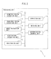
- FIG. 2 is a functional block diagram of the processing unit 7.
- the processing unit 7 includes a biometric region extraction unit 11, an invariable region extraction unit 12, an angle calculation unit 13, a vein pattern extraction unit 14, a registration unit 15, a correction unit 16, a matching unit 17, and an authentication judgment unit 18.
- Each of the units included in the processing unit 7 is a functional module incorporated by the computer program executed on the one or more processors included in the processing unit 7.
- each of the units included in the processing unit 7 may be incorporated as a firmware in the biometric authentication apparatus 1.
- the biometric region extraction unit 11, the invariable region extraction unit 12, the angle calculation unit 13, and the vein pattern extraction unit 14 are used in both of biometric authentication process and registration process. Additionally, the registration unit 15 is used in registration process. On the other hand, the correction unit 16, the matching unit 17, and the authentication judgment unit 18 are used in biometric authentication process.
- Registration process is a process that generates data relating to registered biometric information from a biometric image capturing a hand vein pattern of a registered user, i.e., the registered biometric information, and then causes the storage unit 5 to store the data together with identification information such as a user name of a registered user.
- the data relating to registered biometric information include data obtained from a biometric image of a vein pattern taken with the fingers open and data obtained from a biometric image of a vein pattern taken with the fingers closed. Since the same process is performed on both of the biometric images, the following will describe a process on one of the biometric images, unless otherwise necessary.
- the fingers-open state compared to the fingers-closed state, at least one pair of adjacent two fingers has a relatively large inter-finger open angle.
- the biometric region extraction unit 11 detects, from a biometric image, pixels capturing a part of the hand of the user that have a higher luminance value than a predetermined threshold value.
- the biometric region extraction unit 11 executes labeling process on the detected pixels to extract a biometric region that is a region of the biometric image in which the hand has been partially or entirely captured.
- the predetermined threshold value can be defined, for example, as a value obtained by adding an offset value corresponding to a fluctuation range of luminance values of background pixels capturing nothing to a minimum value of luminance values of respective pixels of the biometric image.
- the biometric region extraction unit 11 generates, as information representing the biometric region, for example, a binary image having the same size as that of the biometric image. Next, the biometric region extraction unit 11 sets the values of pixels included in the biometric region of the binary image to '1' and sets the values of the background pixels to '0'. Then, the biometric region extraction unit 11 sends the information representing the biometric region to the invariable region extraction unit 12, the angle calculation unit 13, and the vein pattern extraction unit 14.
- the invariable region extraction unit 12 extracts an invariable region from the biometric region.
- the invariable region is a region in which a vein pattern included in the invariable region is not deformed regardless of the finger postures.
- Figure 3A is a view depicting an example of a hand vein pattern in a biometric image with fingers open
- Figure 3B is a view depicting an example of a hand vein pattern in a biometric image with the fingers closed
- Figure 3C is a view in which the vein pattern depicted in Figure 3A and the vein pattern depicted in Figure 3B has been superimposed on each other.
- the positions of veins do not vary even when the fingers are moved, so that the region of the vein pattern 301 substantially matches with that of the vein pattern 302.
- the region 303 is an invariable region.
- the invariable region extraction unit 12 obtains a positional deviation amount when the best matching between the two biometric images, for example, by performing a pattern matching while shifting a relative position of the biometric image corresponding to the fingers-closed state with respect to the biometric image corresponding to the fingers-open state.
- the invariable region extraction unit 12 may obtain the positional deviation amount by performing a pattern matching between parts of the respective biometric images including a center of the biometric region. Then, the invariable region extraction unit 12 moves at least one of the two biometric images so as to cancel the positional deviation amount and causes the vein patterns captured in the two biometric images to match with each other as much as possible.
- the invariable region extraction unit 12 divides one of the two biometric images into a plurality of partial regions in the state in which the positions of the vein patterns of the two biometric images are matched with each other.
- a size of each partial region is set, for example, to be smaller than sizes of parts in which the positions of the veins vary depending on the angles of the fingers.
- the invariable region extraction unit 12 obtains a normalized cross correlation value between each partial region including a part of the biometric region and a partial region at a position corresponding thereto in the other biometric image and extracts partial regions having a normalized cross correlation value not less than a predetermined threshold value, as invariable region candidates.
- the predetermined threshold value is set to a lower limit value of the normalized cross correlation value, at which the images of objects captured in two respective partial regions can be regarded as matching with each other, for example, a value of from 0.8 to 0.9.
- the invariable region extraction unit 12 executes labeling process on the invariable region candidates to connect with each other invariable region candidates that are adjacent to each other. Next, the invariable region extraction unit 12 designates the largest among the groups of the connected invariable region candidates as an invariable region.
- a plurality of reference hand model images may be prepared in advance that represent a positional relationship between the outline of a hand and an invariable region, and the reference model images may be stored in the storage unit 5.
- the invariable region extraction unit 12 executes a pattern matching between a biometric image and each of the plurality of reference model images to select a reference model image most closely matching with the biometric image. Then, the invariable region extraction unit 12 may cause the outline of the hand in the selected reference model image to match with the outline of the hand in the biometric image to designate, in this state, a region of the biometric image overlapping with the invariable region set in the reference model image, as an invariable region of the biometric region.
- the invariable region extraction unit 12 sets up a reference coordinate system used as a reference for obtaining the angle of each finger with reference to the invariable region. For example, when the two biometric images are positionally matched with each other as described above, the center of each biometric image is set as an origin of the reference coordinate system in the positionally matched state. Then, the invariable region extraction unit 12 sets up an axis x of the reference coordinate system to be parallel to a horizontal direction of the one of the two biometric images that has not been moved and sets up an axis y of the reference coordinate system to be parallel to a vertical direction of the one of the biometric images.
- the axes x and y of the reference coordinates are set to be directed in directions in which the axes are rotated counterclockwise by the angle ⁇ from the horizontal direction and the vertical direction, respectively, of the image that has been moved.
- the center of each biometric image is set as the origin of the reference coordinate system.
- the axes x and y of the reference coordinate system are also set to be directed in the directions in which the axes are rotated counterclockwise by the angle ⁇ from the horizontal direction and the vertical direction, respectively, of the image.
- the invariable region extraction unit 12 generates, for example, a binary image having the same size as that of the biometric image. Then, the biometric region extraction unit 11 sets the values of pixels included in the invariable region of the binary image to '1' and the values of the other pixels to '0'.
- the invariable region extraction unit 12 sends the information representing the invariable region of each biometric image and the coordinates of the origin and the directions of the coordinate axes in the reference coordinate system set up in the biometric image to the angle calculation unit 13, the vein pattern extraction unit 14, and the registration unit 15.
- the angle calculation unit 13 is an example of a posture specification unit and obtains the angle of each finger captured in the biometric image representing the vein pattern in the fingers-closed state as an example of a first index representing the posture of the fingers. In addition, the angle calculation unit 13 obtains the angle of each finger captured in the biometric image representing the vein pattern in the fingers-open state as an example of a second index representing the posture of the fingers. To obtain them, first, the angle calculation unit 13 obtains a centerline along a longitudinal direction of each finger in the biometric image. Then, the angle calculation unit 13 scans horizontally sequentially from the upper end of the biometric image to detect contour pixels positioned in the contour of the finger that are adjacent to a background region within the biometric region.
- the angle calculation unit 13 extracts the contour pixels as the contour of the finger on the scanning line when the number of pixels of the biometric region sandwiched between adjacent contour pixels corresponds to a lateral width of the finger. Then, the angle calculation unit 13 obtains the contour of each finger by connecting contour pixels adjacent in a substantially vertical direction.
- the angle calculation unit 13 may detect the region capturing the individual fingers in the biometric image by using any of other various techniques for detecting a region capturing fingers in an image.
- the angle calculation unit 13 obtains, in each finger, the coordinates of middle points between left-end contour pixels of the finger and right-end contour pixels thereof at two points with different heights in the axis y direction of the reference coordinate system. Then, the angle calculation unit 13 defines a line connecting the two middle points as the centerline of the finger.
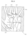
- Figure 4 is a view depicting an example of the angle of each finger.
- each of the axes x and y represents the coordinate axis of the reference coordinate system.
- the angle calculation unit 13 calculates angles ⁇ 1 to ⁇ 5 of respective fingers by regarding angles formed by centerlines 401 to 405 of the respective fingers and the axis x as the angles of the respective fingers.
- the angle calculation unit 13 sends the angles of the respective fingers in each biometric image to the vein pattern extraction unit 14 and the registration unit 15.
- the vein pattern extraction unit 14 is an example of a biometric information extraction unit and extracts the hand vein pattern from the biometric region in the biometric image. To do this, the vein pattern extraction unit 14 binarizes respective pixels in the biometric region into vein pixels capturing the veins and having a pixel value below a predetermined threshold value and the other pixels having a pixel value not less than the predetermined threshold value.
- the predetermined threshold value is set to, for example, a mean value of the values of the pixels in the biometric region.
- the vein pattern extraction unit 14 performs thinning process on the vein pixels of the biometric image extracted by the binarization to generate a vein pattern image in which individual veins are represented by a line having a single-pixel width.
- the vein pattern image is an example of shape data representing a shape of biometric information of a hand.
- the vein pattern extraction unit 14 compares the vein pattern image with the invariable region to specify pixels deviating from the invariable region and capturing veins nearer to the fingers than the invariable region. A part of the veins captured in the specified pixels changes positions thereof depending on the postures of the fingers.
- the specified pixels are hereinafter referred to as variable vein pixels, for convenience.
- the vein pattern extraction unit 14 obtains position specifying information of each variable vein pixel, which is used to find a pair of variable vein pixels capturing the same parts of the veins in the two biometric images when performing vein pattern correction at the time of matching.
- the vein pattern extraction unit 14 detects, along a vein captured in the each variable vein pixel, a pixel at which the vein reaches a boundary of the invariable region as an invariable boundary pixel, and obtains coordinates of the pixel in the reference coordinate system.
- the vein pattern extraction unit 14 detects an invariable boundary pixel corresponding to each variable vein pixel and counts the number of pixels from the variable vein pixel to the invariable boundary pixel along the vein. Then, the vein pattern extraction unit 14 relates the coordinates of the corresponding invariable boundary pixel and the number of pixels from the invariable boundary pixel as position specifying information to each variable vein pixel.
- the vein pattern extraction unit 14 specifies a centerline closest to each variable vein pixel among the centerlines of the respective fingers and relates an identification number of a finger corresponding to the closest centerline to the relevant variable vein pixel.
- the identification number of the finger is also an example of the position specifying information.
- the vein pattern extraction unit 14 sends the vein pattern images and each variable vein pixel and its position specifying information to the registration unit 15.
- the registration unit 15 Upon execution of registration process, the registration unit 15 stores the identification information of the user input through the input unit 3 together with the invariable region representing information, the vein pattern images, the each variable vein pixel and its position specifying information, and the angles of the respective fingers in the storage unit 5. In this way, the user is registered as a registered user allowed use of an apparatus incorporating the biometric authentication apparatus 1.
- FIG. 5 is an operational flowchart of registration process executed by the processing unit 7.
- the processing unit 7 receives the two biometric images representing the vein patterns of the hand of the user captured in the fingers-open state and in the fingers-closed state from the biometric information acquisition unit 4. Then, the biometric region extraction unit 11 of the processing unit 7 extracts a biometric region from each of the biometric images (step S101).
- the invariable region extraction unit 12 of the processing unit 7 extracts, from the biometric region of the each biometric image, an invariable region that is a region where positions of the veins do not vary even when the angles of the fingers vary (step S102). In addition, the invariable region extraction unit 12 sets up a reference coordinate system based on the invariable region in the each biometric image (step S103).
- the angle calculation unit 13 of the processing unit 7 calculates an angle of each finger according to the reference coordinate system in the each biometric image (step S104).
- the vein pattern extraction unit 14 of the processing unit 7 extracts the vein pattern from the each biometric image and performs binarization and thinning process to generate a vein pattern image corresponding to the fingers-open state and a vein pattern image corresponding to the fingers-closed state (step S105).
- the vein pattern extraction unit 14 obtains position specifying information of each of variable vein pixels positioned between the each finger and the invariable region (step S106).
- the registration unit 15 of the processing unit 7 stores the identification information of the user obtained from the input unit 3 together with the invariable region representing information corresponding to the fingers-closed state and the fingers-open state, the vein pattern images, the each variable vein pixel and its position specifying information, and the angles of the respective fingers in the storage unit 5 (step S107). Then, the processing unit 7 ends the registration process.
- the biometric authentication process may be executed according to either a so-called 1:1 authentication system in which a registered user as an object for matching is identified by obtaining the identification information of a registered user through the input unit 3 or a so-called 1:N authentication system in which a registered user as an object for matching is not identified.
- the processes of the biometric region extraction unit 11, the invariable region extraction unit 12, the angle calculation unit 13, and the vein pattern extraction unit 14 are performed on an input biometric image generated at the time of execution of the biometric authentication process. Then, the angles of respective fingers are calculated and a vein pattern image is generated.
- the biometric authentication apparatus 1 Upon execution of the biometric authentication process, the biometric authentication apparatus 1 generates only one input biometric image.
- the invariable region extraction unit 12 specifies an invariable region by a pattern matching between the input biometric image and the reference model image.
- the invariable region extraction unit 12 may specify an invariable region in the input biometric image by a pattern matching between a registered biometric image in either the fingers-closed state or the fingers-open state specified according to the identification information of a user input through the input unit 3 and the input biometric image.
- the correction unit 16 obtains, as a position correction coefficient for each finger, a ratio of a difference between the angle of the finger obtained from the input biometric image and the angle of the finger in the fingers-closed state or the fingers-open state to a difference between the angle of the finger in the fingers-closed state and the angle thereof in the fingers-open state. Then, the correction unit 16 corrects the vein pattern in the fingers-closed state or the vein pattern in the fingers-open state so as to cancel a difference in the shape between the vein patterns due to the difference of the angles of the fingers according to the position correction coefficients.
- ⁇ represents an angle of a finger of interest with respect to the axis x of the reference coordinate system in the input biometric image
- ⁇ c and ⁇ o represent an angle of the finger of interest with respect to the axis x of the reference coordinate system on the biometric image in the fingers-closed state and on the biometric image in the fingers-open state, respectively.
- the correction unit 16 sets, for each finger, an internally dividing point related to the finger between the pairs of variable vein pixels capturing the same venous portion in the biometric image in the fingers-closed state and in the biometric image in the fingers-open state, to a positionally corrected pixel capturing the same venous portion.
- vc(x, y) represents a position of the variable vein pixel in the vein pattern image with the fingers closed; and "vo(x,y)” represents a position of the variable vein pixel in the vein pattern image with the fingers open, in which the same portion as a part of the veins captured in the vc(x, y) is captured.
- the correction unit 16 specifies a pair of variable vein pixels capturing the same venous portion according to the following procedures.
- the correction unit 16 detects a pair of an invariable boundary pixel in the vein pattern image with the fingers closed and an invariable boundary pixel in the vein pattern image with the fingers open, whose coordinates in the reference coordinate system are the same as or substantially the same as those of the former pixel. It is presumed that the same venous portion is captured in the two invariable boundary pixels. Accordingly, the correction unit 16 determines two variable vein pixels each connected to one of the invariable boundary pixels along the vein and have an equal distance along the vein from one thereof in each vein pattern image as a pair of variable vein pixels capturing the same venous portion.
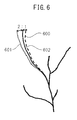
- Figure 6 is a view depicting an example of a vein pattern positionally corrected from a vein pattern of the fingers-open state and a vein pattern of the fingers-closed state.
- a vein pattern 600 is a vein pattern near an index finger extracted from a biometric image taken in a fingers-closed state; and a vein pattern 601 is a vein pattern near the index finger extracted from a biometric image taken in a fingers-open state.
- an angle of the index finger with respect to the axis x of the reference coordinate system in the fingers-closed state is set to 90 degrees
- an angle of the index finger with respect to the axis x of the reference coordinate system in the fingers-open state is set to 120 degrees.
- the positionally corrected vein pattern 602 is in a position internally dividing the distance between the vein pattern 600 and the vein pattern 601 into 1:2.
- the correction unit 16 sends the corrected vein pattern image representing a vein pattern positionally corrected based on the two vein pattern images of a registered user together with identification information of the registered user to the matching unit 17.
- the correction unit 16 performs the above process on all registered users to generate a corrected vein pattern image of each registered user and sends the corrected vein pattern image and identification information of the registered user to the matching unit 17.
- the matching unit 17 matches the input vein pattern image generated from the input biometric image and the corrected vein pattern image to calculate a degree of similarity between the vein pattern depicted in the input vein pattern image and the corrected vein pattern depicted in the corrected vein pattern image.
- the matching unit 17 may calculate the degree of similarity by performing a pattern matching between the input vein pattern image and the corrected vein pattern image.
- the matching unit 17 obtains normalized cross correlation values while changing a relative position of the input vein pattern image with respect to the corrected vein pattern image and calculates a maximum value of the normalized cross correlation values as a similarity value.
- the matching unit 17 may extract feature points such as venous bifurcations or endings from each of the input vein pattern image and the corrected vein pattern image and may calculate a degree of matching between the feature points as the degree of similarity.
- the matching unit 17 scans on each of the input vein pattern image and the corrected vein pattern image by using a plurality of templates corresponding to either venous bifurcations or venous endings. Then, the matching unit 17 detects, as feature points, positions of those points in the vein pattern images matching with any of the templates.
- the matching unit 17 obtains the number of feature points matching between feature points detected from the input vein pattern image and those detected from the corrected vein pattern image. Then, the matching unit 17 can calculate the degree of similarity by dividing the number of the matching feature points by the number of the feature points detected from the input vein pattern image.
- the matching unit 17 sends the degree of similarity together with the identification information of the registered user to the authentication judgment unit 18.
- the matching unit 17 executes the above process on each registered user to obtain the degree of similarity in the each registered user. Then, the matching unit 17 selects a registered user having a maximum degree of similarity.
- the matching unit 17 sends a maximum value of the degree of similarity and identification information of the registered user corresponding to the maximum value to the authentication judgment unit 18.
- the authentication judgment unit 18 compares the degree of similarity with an authentication judgment threshold value to judge whether or not to authenticate the user as the registered user. For example, the authentication judgment unit 18 judges that the vein pattern of the user captured in the input biometric image matches with the vein pattern of the registered user when the degree of similarity is not less than the authentication judgment value. Then, the authentication judgment unit 18 authenticates the user as the registered user. The authentication judgment unit 18 notifies the authentication result to the processing unit 7 after authentication of the user. Then, the processing unit 7 allows the authenticated user to use an apparatus incorporating the biometric authentication apparatus 1 or an apparatus connected with the biometric authentication apparatus 1.
- the authentication judgment unit 18 does not authenticate the user and notifies the processing unit 7 that the user has not been authenticated. In this case, the processing unit 7 refuses to allow the user to use an apparatus incorporating the biometric authentication apparatus 1 or an apparatus connected therewith. Additionally, the processing unit 7 may allow the display unit 2 to display a message indicating the authentication failure.
- the authentication judgment threshold value is preferably set to a value allowing the authentication judgment unit 18 to succeed in authentication only when the registered user himself or herself is the user.
- the authentication judgment threshold value is preferably set to a value allowing the authentication judgment unit 18 to fail in authentication when someone else different from the registered user is the user.
- the authentication judgment threshold value may be a value obtained by adding a value obtained by multiplying a difference between a possible maximum value and a possible minimum value of the degree of similarity by 0.7 to the minimum value of the degree of similarity.
- FIG. 7 is an operational flowchart of biometric authentication process executed by the processing unit 7.
- the biometric region extraction unit 11 of the processing unit 7 extracts a biometric region from the input biometric image (step S201).
- the invariable region extraction unit 12 of the processing unit 7 extracts an invariable region that is a region in which venous positions are invariable even when the angles of fingers vary, from the biometric region in the input biometric image (step S202). Then, the invariable region extraction unit 12 sets up a reference coordinate system with reference to the invariable region in the input biometric image (step S203).
- the angle calculation unit 13 of the processing unit 7 calculates an angle of each finger according to the reference coordinate system in the input biometric image (step S204). Then the angle calculation unit 13 notifies the angle of each finger to the correction unit 16 of the processing unit 7.
- the vein pattern extraction unit 14 of the processing unit 7 extracts the vein pattern from the input biometric image and performs binarization and thinning process to generate an input vein pattern image representing the shape of the hand vein pattern of the user (step S205). Then, the vein pattern extraction unit 14 sends the input vein pattern image to the matching unit 17 of the processing unit 7.
- the correction unit 16 calculates, as a position correction ratio for each finger, an internal division of an angle of the each finger between the fingers-closed state and the fingers-open state according to the angle of the finger in a biometric image obtained at the time of biometric authentication (step S206). Then, the correction unit 16 corrects the positions of the corresponding variable vein pixels in the vein pattern image with the fingers closed and the vein pattern image with the fingers open to generate a corrected vein pattern image (step S207). Then, the correction unit 16 sends the corrected vein pattern image to the matching unit 17.
- the matching unit 17 calculates a degree of similarity between the vein pattern in the input vein pattern image and the vein pattern in the corrected vein pattern image (step S208). Next, the matching unit 17 sends the identification information of a registered user together with the degree of similarity to the authentication judgment unit 18 of the processing unit 7. When the identification number of the user is not available, the matching unit 17 obtains a maximum value of the degree of similarity obtained regarding each registered user. Then, the matching unit 17 sends, together with the maximum value, the identification information of a registered user corresponding to the maximum value to the authentication judgment unit 18.
- the authentication judgment unit 18 judges whether the degree of similarity is not less than the authentication judgment threshold value (step S209).
- step S209 - Yes the authentication judgment unit 18 authenticates the user as the registered user (step S210).
- step S209 - No when the degree of the similarity is below the authentication judgment threshold value (step S209 - No), the authentication judgment unit 18 does not authenticate the user (step S211).
- the processing unit 7 ends the biometric authentication process.
- the biometric authentication apparatus obtains in advance an index representing the posture of fingers from each of two biometric images taken in the states in which the postures of the fingers affecting the shape of biometric information of a hand are different from each other. Additionally, the biometric authentication apparatus obtains an index representing the posture of fingers from an input biometric image acquired at the time of matching. Then, based on the index at the time of the matching and the indexes at the time of the registration, the biometric authentication apparatus reshapes data representing the shape of the biometric information at the time of registration so as to cancel a difference in the shape between the pieces of the biometric information due to a difference between the finger posture at the time of registration and that at the time of biometric authentication.
- the biometric authentication apparatus executes matching process using the reshaped biometric information. Therefore, the biometric authentication apparatus can suppress reduction in accuracy of genuine identity authentication even when local deformation due to the posture of fingers is included in hand biometric information captured in a biometric image at the time of matching against hand biometric information captured in a biometric image at the time of registration.
- the biometric authentication apparatus may use, as an index representing the posture of fingers, a distance between the roots of adjacent fingers instead of the angles of fingers.
- Figure 8 is a functional block diagram of a processing unit according to the modified example.
- a processing unit 71 includes a biometric region extraction unit 11, an invariable region extraction unit 12, an inter-finger distance calculation unit 19, a vein pattern extraction unit 14, a registration unit 15, a correction unit 16, a matching unit 17, and an authentication judgment unit 18.
- the respective constituent elements included in the processing unit 71 are given the same reference numerals as those of the corresponding constituent elements of the processing unit 7 depicted in Figure 2 .
- the processing unit 71 depicted in Figure 8 is different from the processing unit 7 depicted in Figure 2 in terms of including the inter-finger distance calculation unit 19 instead of the angle calculation unit 13. Thus, a description below will be given of the inter-finger distance calculation unit 19 and portions relevant thereto.
- the inter-finger distance calculation unit 19 is another example of the posture specification unit.
- the inter-finger distance calculation unit 19 calculates a distance between the roots of two fingers adjacent to each other in a biometric image representing a vein pattern in the fingers-closed state and a distance between the roots of two fingers adjacent to each other in a biometric image representing a vein pattern in the fingers-open state, as indexes representing the respective postures of the fingers.
- the inter-finger distance calculation unit 19 sequentially tracks contour pixels representing the contour of each finger in order from an upper side to a lower side of the biometric image to obtain the coordinates of connecting points at which contour pixels of the adjacent fingers are connected to each other, in the axis y direction of the reference coordinate system.
- the inter-finger distance calculation unit 19 designates, of the left and right connecting points of a finger of interest, a connecting point closer to the upper end of the biometric image as a connecting point corresponding to the root of the finger.
- the inter-finger distance calculation unit 19 designates the detected connecting points as those corresponding to the roots of the thumb and the little finger.
- the inter-finger distance calculation unit 19 designates, for each finger, an intersection point of a perpendicular line drawn down from the connecting point of the finger to the centerline thereof and the centerline as a root position of the finger. Then, the inter-finger distance calculation unit 19 calculates a distance between the root positions of the adjacent fingers as an inter-finger distance.
- the modified example also, at the time of registration, there are obtained a biometric image of a hand vein pattern in the fingers-open state and a biometric image of a hand vein pattern in the fingers-closed state. Then, inter-finger distances in each of the biometric images are calculated. The inter-finger distances are stored together with the vein pattern images, variable vein pixels, position specifying information, and the like in the storage unit.
- the inter-finger distance calculation unit 19 calculates a distance between the root positions of adjacent fingers from an input biometric image. Then, the correction unit 16 calculates position correction coefficients rc and ro using the inter-finger distance instead of the angles of the fingers in the equation (1).
- the correction unit 16 uses position correction coefficients calculated based on the inter-finger distance of two fingers of interest to correct the positions of variable vein pixels positioned between the respective centerlines of the two fingers.
- shape data representing the shape of biometric information of a hand may include the coordinates of feature points such as venous bifurcations and endings.
- the vein pattern extraction unit may extract the feature points by performing a template matching between a vein pattern image and a template representing bifurcations or endings at the time of matching and at the time of registration, as described in relation to the matching unit.
- the correction unit selects a second feature point closest to a first feature point outside the invariable region in the vein pattern image with the fingers closed, among feature points outside the invariable region in the vein pattern image with the fingers open in the reference coordinate system. Then, the correction unit applies the equation (2) using coordinates of the first feature point as vc(x, y) and coordinates of the second feature point as vc(x, y), thereby correcting the positions of the feature points.
- biometric information of a hand to be used by the present embodiment or the modified examples is not limited to a hand vein pattern.
- a palm print may be used as the biometric information of a hand.
- biometric authentication apparatus and the biometric authentication method disclosed in the present specification are applicable to various apparatuses or systems that execute biometric authentication process between biometric information of a user and pre-registered biometric information to allow the user to perform an operation.
- Figure 9 is a schematic structural diagram of an example of a computer system that incorporates the biometric authentication apparatus according to any one of the respective embodiments or the modified examples thereof.
- a computer system 100 includes at least one terminal 110 and a server 120.
- the terminal 110 and the server 120 are connected through a wired or wireless communication network 130.
- constituent elements included in the computer system 100 in Figure 9 constituent elements corresponding to any of those included in the biometric authentication apparatus 1 depicted in Figure 1 are given the same reference numerals as those of the constituent elements in the biometric authentication apparatus 1.
- the terminal 100 is, for example, a mobile terminal such as a mobile phone or a tablet terminal, or a fixed terminal, and includes a display unit 2, an input unit 3, and a biometric information acquisition unit 4.
- the terminal 110 further includes a storage unit 21, an image acquisition control unit 22, and an interface unit 23.
- the storage unit 21 includes, for example, a semiconductor memory circuit to temporarily store a biometric image generated by the biometric information acquisition unit 4.
- the image acquisition control unit 22 includes one or more processors and peripheral circuits thereof to control each unit of the terminal 110 and execute various programs operated on the terminal 110.
- the image acquisition control unit 22 transmits biometric images capturing hand vein patterns generated by the biometric information acquisition unit 4 to the server 120 through the interface unit 23 including an interface circuit for connecting the terminal 110 with the communication network 130.
- the image acquisition control unit 22 may also transmit user identification information input through the input unit 3 to the server 120.
- the server 120 includes a storage unit 5, a processing unit 7, and an interface unit 24 including an interface circuit for connecting the server 120 with the communication network 130.
- the processing unit 7 of the server 120 executes biometric authentication process by implementing each function of the processing unit according to any one of the above embodiments or the modified examples thereof using the biometric images received through the interface unit 24. Then, the server 120 returns a judgment result on success or failure in authentication to the terminal 110 through the interface unit 24.
- the image acquisition control unit 22 may execute the processes of the biometric region extraction unit, the invariable region extraction unit, the angle calculation unit or the inter-finger distance calculation unit, and the vein pattern extraction unit among the functions of the processing unit according to any one of the embodiments or the modified examples.
- data relating to biometric information extracted from the biometric image of a user and identification information of the user may be transmitted from the terminal 110 to the server 120.
- the processing unit 7 of the server 120 executes only the processes of the matching unit, the authentication judgment unit, and the registration unit among the functions of the processing unit according to the respective embodiments. This reduces load on the server 120, so that the computer system 100 can reduce a waiting time of the user even when a plurality of biometric authentication processes are simultaneously executed.
- a computer program including commands that cause a computer to execute the functions of the processing unit according to each of the above embodiments may be provided in a form stored on a recorded medium such as a magnetic recording medium, an optical recording medium, or a nonvolatile semiconductor memory.
Landscapes
- Engineering & Computer Science (AREA)
- Human Computer Interaction (AREA)
- Physics & Mathematics (AREA)
- General Physics & Mathematics (AREA)
- Multimedia (AREA)
- Theoretical Computer Science (AREA)
- Health & Medical Sciences (AREA)
- General Health & Medical Sciences (AREA)
- Vascular Medicine (AREA)
- Collating Specific Patterns (AREA)
- Measurement Of The Respiration, Hearing Ability, Form, And Blood Characteristics Of Living Organisms (AREA)
Abstract
Description
- The present invention relates to a biometric authentication apparatus, a biometric authentication method, and a computer program for biometric authentication that use an image capturing biometric information of, for example, a hand during biometric authentication.
- Recent years have seen development of biometric authentication techniques for judging whether or not to authenticate an individual using biometric information such as a fingerprint or a hand vein pattern. Biometric authentication techniques are widely used, from large-scale systems with a number of registered users, such as access control systems, border control systems, or national identification number systems, to apparatuses used by specific individuals, such as computers or mobile terminals.
- For example, in order to use a hand vein pattern as biometric information, a biometric authentication apparatus acquires a biometric image representing the vein pattern as an input biometric image. Then, the biometric authentication apparatus matches the input biometric information that is the vein pattern of a user represented in the input biometric image with registered biometric information that is a hand vein pattern represented in a biometric image of a registered user registered in advance. The biometric authentication apparatus authenticates the user as the registered user having proper authority when it judges that the input biometric information matches with the registered biometric information based on a result of the matching process. Additionally, the biometric authentication apparatus allows the user to use an apparatus incorporating the biometric authentication apparatus or another apparatus connected with the biometric authentication apparatus.
- When a user registers biometric information in the biometric authentication apparatus (hereinafter referred to simply as "at the time of registration"), a posture of a body part including the biometric information is preferably the same as a posture of the body part when matching biometric information of the user and biometric information of a registered user is performed (hereinafter referred to simply as "at the time of matching"). The use of the same posture at the time of matching and at the time of registration increases a degree of similarity between a shape of biometric information captured in a biometric image obtained at the time of registration and a shape of biometric information captured in a biometric image obtained at the time of matching. As a result, a genuine acceptance rate is improved. However, practically, even when the registered user himself or herself requests authentication as a user, the posture of the body part including biometric information at the time of registration sometimes differs from the posture of the body part at the time of matching. Accordingly, the shape of biometric information captured in a biometric image obtained at the time of registration does not completely match with the shape of biometric information captured in a biometric image obtained at the time of matching.
- Thus, techniques have been proposed for performing matching process by correcting or considering a difference between the shape of biometric information in an image at the time of registration and the shape of biometric information in an image at the time of matching due to a difference in posture (for example, see
Patent Literature 1 or 2). - For example,
Patent Literature 1 discloses a palm-shape authentication method for matching a palm-shape image and a registered palm-shape image by detecting a rotation angle of a hand from palm-shape image data and correcting a positional deviation from a rotation angle of a registered hand in a registered palm-shape image registered in advance by detecting a palm-shape of a user. - In addition,
Patent Literature 2 discloses a biometric authentication apparatus that performs authentication by comparing at least a vein pattern image of a subject and a template of the subject based on evaluation results on a relative position between a skin surface pattern image of the subject and the template thereof. -
- Patent Literature 1: Japanese Laid-open Patent Publication No.
2002-117405 - Patent Literature 2: Japanese Laid-open Patent Publication No.
2010-15365 - The technique disclosed in
Patent Literature - Therefore, it is an object of the present invention to provide a biometric authentication apparatus that can suppress reduction in authentication accuracy even when local deformation is included in biometric information of a hand captured in a biometric image at the time of matching against biometric information of the hand captured in a biometric image taken at the time of registration.
- According to one embodiment, a biometric authentication apparatus is provided. The biometric authentication apparatus includes a storage unit which stores first shape data representing a shape of biometric information of a hand of a registered user in a state in which fingers of the hand take a first posture, a first index representing the first posture, second shape data representing a shape of biometric information of the hand of the registered user in a state in which the fingers of the hand take a second posture, and a second index representing the second posture; a biometric information acquisition unit which generates a biometric image representing biometric information of a hand of a user; a posture specification unit which calculates a third index representing a third posture of fingers of the hand of the user captured in the biometric image from the biometric image; a biometric information extraction unit which generates third shape data representing a shape of the biometric information of the hand of the user captured in the biometric image based on the biometric image; a correction unit which obtains corrected shape data by correcting the first shape data or the second shape data so as to cancel a shape difference of the biometric information due to a difference between the third posture and the first posture or the second posture according to a ratio of a difference between the third index and the first index or the second index to a difference between the first index and the second index; and a matching unit which matches the third shape data and the corrected shape data to obtain a degree of similarity between the biometric information of the hand of the user and the biometric information of the hand of the registered user.
- The object and advantages of the invention will be accomplished and attained by means of the elements and combinations particularly pointed out in the claims.
- It is to be understood that both the foregoing general description and the following detailed description are exemplary and explanatory but not restrictive of the invention, as claimed.
- A biometric authentication apparatus disclosed in the present specification can suppress reduction in authentication accuracy even when local deformation is included in biometric information of a hand captured in a biometric image at the time of matching against biometric information of the hand captured in a biometric image at the time of registration.
-
-
Figure 1 is a schematic structural diagram of a biometric authentication apparatus. -
Figure 2 is a functional block diagram of a processing unit according to one embodiment. -
Figure 3A is a view depicting an example of a hand vein pattern in a biometric image with fingers open;Figure 3B is a view depicting an example of a hand vein pattern in a biometric image with the fingers closed; andFigure 3C is a view obtained as a result of superimposition of the vein pattern ofFigure 3A and the vein pattern ofFigure 3B . -
Figure 4 is a view depicting an example of an angle of each finger. -
Figure 5 is a diagram depicting an operational flowchart of registration process. -
Figure 6 is a view depicting an example of a vein pattern positionally corrected from a vein pattern of a fingers-open state and a vein pattern of a fingers-closed state according to an angle of the finger. -
Figure 7 is a diagram depicting an operational flowchart of biometric authentication process. -
Figure 8 is a functional block diagram of a processing unit according to a modified example. -
Figure 9 is a schematic structural diagram of a computer system incorporating a biometric authentication apparatus according to one embodiment or a modified example thereof. - Hereinafter, a description will be given of a biometric authentication apparatus according to one embodiment of the invention with reference to the drawings.
- The biometric authentication apparatus uses, in biometric authentication, a biometric image capturing a hand vein pattern that is an example of biometric information of a hand of a user. The biometric authentication apparatus acquires a biometric image representing a hand vein pattern in a state with fingers of the user open and a biometric image representing a hand vein pattern in a state with the fingers thereof closed at the time of registration in order to correct partial deformation of a vein pattern occurring near roots of the fingers due to a difference in the degree of openness of the fingers. Then, for each of the two biometric images, the biometric authentication apparatus registers an angle of each of the fingers and a vein position near the root of corresponding finger together with data representing a shape of the vein pattern. In addition, the biometric authentication apparatus obtains an angle of each finger from a biometric image acquired at the time of matching and corrects the vein position near the each finger in the data representing the shape of the registered vein pattern according to a difference between the angle obtained above and the angle of the each finger in each of the two biometric images obtained at the time of the registration. Then, the biometric authentication apparatus matches data representing a shape of the vein pattern with the corrected vein position and data representing a shape of a vein pattern obtained from the biometric image acquired at the time of the matching. In this way, the biometric authentication apparatus suppresses reduction in the genuine acceptance rate due to local deformation in the vein pattern caused by the difference between the finger posture at the time of registration and that at the time of matching. The hand vein pattern may be a vein pattern of either the palm or the back of the hand.
- In the present specification, the term "matching process" is used to refer to process for calculating an index representing a degree of difference or a degree of similarity between the biometric information of a user and the biometric information of a registered user. Additionally, the term "biometric authentication process" is used to refer not only to matching process but also to entire authentication process including process for determining whether or not to authenticate a user by using indexes obtained by the matching process.
-
Figure 1 depicts a schematic structural diagram of a biometric authentication apparatus. As depicted inFigure 1 , abiometric authentication apparatus 1 includes adisplay unit 2, aninput unit 3, a biometricinformation acquisition unit 4, astorage unit 5, a storagemedium access device 5, and aprocessing unit 7. Thedisplay unit 2, theinput unit 3, and the biometricinformation acquisition unit 4 may be provided independently of a housing that houses thestorage unit 5, the storagemedium access device 6, and theprocessing unit 7. - The
biometric authentication apparatus 1 executes biometric authentication process by using a biometric image representing a hand vein pattern of a user generated by the biometricinformation acquisition unit 4 to match the vein pattern against a vein pattern of a registered user. Then, when thebiometric authentication apparatus 1 authenticates the user as any one of registered users as a result of the biometric authentication, the user is allowed to use an apparatus incorporating thebiometric authentication apparatus 1. Alternatively, thebiometric authentication apparatus 1 transmits a signal indicating the acceptance of the user to another apparatus (not depicted) to allow the user to use the other apparatus. - The
display unit 2 includes a display device, for example, such as a liquid crystal display or an organic electroluminescence display. Thedisplay unit 2 displays a message indicating a result of biometric authentication process executed by theprocessing unit 7, various kinds of application-related information, and the like. - The
input unit 3 includes a user interface, for example, such as a keyboard, a mouse, or a touch pad. Then, user identification information such as a user name, a command, or data input by a user through theinput unit 3 is sent to theprocessing unit 7. However, when the user does not have to input information other than biometric information into thebiometric authentication apparatus 1, theinput unit 3 may be omitted. - The biometric
information acquisition unit 4 includes a vein sensor for generating a biometric image capturing a hand vein pattern of a user. The vein sensor includes, for example, a housing that allows the user to place his or her hand thereon, an infrared ray emitting diode arranged in the housing, an area sensor, and an image-forming optical system. The infrared ray emitting diode applies light to the hand placed on the housing. The image-forming optical system forms a vein pattern image of the hand applied light from the infrared ray emitting diode on the area sensor. The area sensor includes two-dimensionally arranged solid state image sensing devices sensitive to infrared ray. Each of the solid state sensing devices outputs a signal in accordance with the intensity of infrared ray, thereby generating a biometric image capturing the hand vein pattern image. Each pixel of the biometric image has a value, for example, in a range of from 0 to 255. The higher the luminance of the pixel, the larger the value of the pixel. In the present embodiment, a region capturing veins and a region not capturing the hand on the biometric image are dark, whereas a region of the hand without the veins is bright. - In the present embodiment, the biometric image is generated in such a manner that tips of the fingers are positioned on an upper end of the biometric image and parts of the fingers on a wrist side are positioned on a lower end thereof.
- Every time the biometric
information acquisition unit 4 generates a biometric image, the biometric image is sent to theprocessing unit 7. - The
storage unit 5 includes at least any one of, for example, a semiconductor memory, a magnetic disc device, or an optical disc device. Thestorage unit 5 then stores an application program used in thebiometric authentication apparatus 1, a user name of at least one registered user, a user identification number thereof, personal setting information thereof, various kinds of data, and the like. In addition, thestorage unit 5 stores a program for executing biometric authentication process. Furthermore, for each registered user, thestorage unit 5 stores data relating to a hand vein pattern that is registered biometric information of the registered user together with identification information of the registered user, such as the user name of the registered user and a password thereof. In the present embodiment, data relating to the registered biometric information includes, for example, images representing vein pattern shapes and the angle of each finger obtained from biometric images having hand vein patterns captured in the fingers-open state and the fingers-closed state. - The storage
medium access device 6 is a device that gains access to thestorage medium 8, for example, such as a magnetic disc, a semiconductor memory card, or an optical storage medium. The storagemedium access device 6 reads, for example, a computer program for biometric authentication stored in thestorage medium 8 and executed in theprocessing unit 7 and sends to theprocessing unit 7 or causes thestorage unit 5 to store the program. - The
processing unit 7 includes one or more processors and peripheral circuits thereof. Then, theprocessing unit 7 executes biometric authentication process or registration process using biometric images acquired from the biometricinformation acquisition unit 4. -
Figure 2 is a functional block diagram of theprocessing unit 7. As depicted inFigure 2 , theprocessing unit 7 includes a biometricregion extraction unit 11, an invariableregion extraction unit 12, anangle calculation unit 13, a veinpattern extraction unit 14, aregistration unit 15, acorrection unit 16, amatching unit 17, and anauthentication judgment unit 18. Each of the units included in theprocessing unit 7 is a functional module incorporated by the computer program executed on the one or more processors included in theprocessing unit 7. Alternatively, each of the units included in theprocessing unit 7 may be incorporated as a firmware in thebiometric authentication apparatus 1. - The biometric
region extraction unit 11, the invariableregion extraction unit 12, theangle calculation unit 13, and the veinpattern extraction unit 14 are used in both of biometric authentication process and registration process. Additionally, theregistration unit 15 is used in registration process. On the other hand, thecorrection unit 16, the matchingunit 17, and theauthentication judgment unit 18 are used in biometric authentication process. - Hereinafter, first, a registration process executed by the
processing unit 7 will be described, and then followed by a description of biometric authentication process. - Registration process is a process that generates data relating to registered biometric information from a biometric image capturing a hand vein pattern of a registered user, i.e., the registered biometric information, and then causes the
storage unit 5 to store the data together with identification information such as a user name of a registered user. In the present embodiment, as described above, the data relating to registered biometric information include data obtained from a biometric image of a vein pattern taken with the fingers open and data obtained from a biometric image of a vein pattern taken with the fingers closed. Since the same process is performed on both of the biometric images, the following will describe a process on one of the biometric images, unless otherwise necessary. In the fingers-open state compared to the fingers-closed state, at least one pair of adjacent two fingers has a relatively large inter-finger open angle. - The biometric
region extraction unit 11 detects, from a biometric image, pixels capturing a part of the hand of the user that have a higher luminance value than a predetermined threshold value. The biometricregion extraction unit 11 executes labeling process on the detected pixels to extract a biometric region that is a region of the biometric image in which the hand has been partially or entirely captured. The predetermined threshold value can be defined, for example, as a value obtained by adding an offset value corresponding to a fluctuation range of luminance values of background pixels capturing nothing to a minimum value of luminance values of respective pixels of the biometric image. - The biometric
region extraction unit 11 generates, as information representing the biometric region, for example, a binary image having the same size as that of the biometric image. Next, the biometricregion extraction unit 11 sets the values of pixels included in the biometric region of the binary image to '1' and sets the values of the background pixels to '0'. Then, the biometricregion extraction unit 11 sends the information representing the biometric region to the invariableregion extraction unit 12, theangle calculation unit 13, and the veinpattern extraction unit 14. - The invariable
region extraction unit 12 extracts an invariable region from the biometric region. The invariable region is a region in which a vein pattern included in the invariable region is not deformed regardless of the finger postures. -
Figure 3A is a view depicting an example of a hand vein pattern in a biometric image with fingers open;Figure 3B is a view depicting an example of a hand vein pattern in a biometric image with the fingers closed; andFigure 3C is a view in which the vein pattern depicted inFigure 3A and the vein pattern depicted inFigure 3B has been superimposed on each other. - Near the root of a finger, the position of a vein connected to the finger varies depending on the angle of the finger. Accordingly, comparison of a
vein pattern 301 captured in animage 300 depicted inFigure 3A with avein pattern 302 captured in animage 310 depicted inFigure 3B indicates that there is a difference in parts near the roots of the fingers between the vein patterns. This is obvious, for example, by referring toFigure 3C . - On the other hand, in a
region 303 depicted inFigure 3C , the positions of veins do not vary even when the fingers are moved, so that the region of thevein pattern 301 substantially matches with that of thevein pattern 302. Thus, theregion 303 is an invariable region. - The invariable
region extraction unit 12 obtains a positional deviation amount when the best matching between the two biometric images, for example, by performing a pattern matching while shifting a relative position of the biometric image corresponding to the fingers-closed state with respect to the biometric image corresponding to the fingers-open state. The invariableregion extraction unit 12 may obtain the positional deviation amount by performing a pattern matching between parts of the respective biometric images including a center of the biometric region. Then, the invariableregion extraction unit 12 moves at least one of the two biometric images so as to cancel the positional deviation amount and causes the vein patterns captured in the two biometric images to match with each other as much as possible. - The invariable
region extraction unit 12 divides one of the two biometric images into a plurality of partial regions in the state in which the positions of the vein patterns of the two biometric images are matched with each other. A size of each partial region is set, for example, to be smaller than sizes of parts in which the positions of the veins vary depending on the angles of the fingers. Then, the invariableregion extraction unit 12 obtains a normalized cross correlation value between each partial region including a part of the biometric region and a partial region at a position corresponding thereto in the other biometric image and extracts partial regions having a normalized cross correlation value not less than a predetermined threshold value, as invariable region candidates. The predetermined threshold value is set to a lower limit value of the normalized cross correlation value, at which the images of objects captured in two respective partial regions can be regarded as matching with each other, for example, a value of from 0.8 to 0.9. - The invariable
region extraction unit 12 executes labeling process on the invariable region candidates to connect with each other invariable region candidates that are adjacent to each other. Next, the invariableregion extraction unit 12 designates the largest among the groups of the connected invariable region candidates as an invariable region. - Alternatively, a plurality of reference hand model images may be prepared in advance that represent a positional relationship between the outline of a hand and an invariable region, and the reference model images may be stored in the
storage unit 5. In this case, the invariableregion extraction unit 12 executes a pattern matching between a biometric image and each of the plurality of reference model images to select a reference model image most closely matching with the biometric image. Then, the invariableregion extraction unit 12 may cause the outline of the hand in the selected reference model image to match with the outline of the hand in the biometric image to designate, in this state, a region of the biometric image overlapping with the invariable region set in the reference model image, as an invariable region of the biometric region. - Next, the invariable
region extraction unit 12 sets up a reference coordinate system used as a reference for obtaining the angle of each finger with reference to the invariable region. For example, when the two biometric images are positionally matched with each other as described above, the center of each biometric image is set as an origin of the reference coordinate system in the positionally matched state. Then, the invariableregion extraction unit 12 sets up an axis x of the reference coordinate system to be parallel to a horizontal direction of the one of the two biometric images that has not been moved and sets up an axis y of the reference coordinate system to be parallel to a vertical direction of the one of the biometric images. Accordingly, for example, when the other one of the biometric images that has been moved is rotated clockwise by an angle θ, the axes x and y of the reference coordinates are set to be directed in directions in which the axes are rotated counterclockwise by the angle θ from the horizontal direction and the vertical direction, respectively, of the image that has been moved. - In addition, even when the invariable region of each of the biometric images is set up based on the reference model image, the center of each biometric image is set as the origin of the reference coordinate system. Additionally, when the biometric image is rotated clockwise by the angle θ with respect to the reference model image, the axes x and y of the reference coordinate system are also set to be directed in the directions in which the axes are rotated counterclockwise by the angle θ from the horizontal direction and the vertical direction, respectively, of the image.
- Furthermore, as information representing the invariable region of each biometric image, the invariable
region extraction unit 12 generates, for example, a binary image having the same size as that of the biometric image. Then, the biometricregion extraction unit 11 sets the values of pixels included in the invariable region of the binary image to '1' and the values of the other pixels to '0'. - The invariable
region extraction unit 12 sends the information representing the invariable region of each biometric image and the coordinates of the origin and the directions of the coordinate axes in the reference coordinate system set up in the biometric image to theangle calculation unit 13, the veinpattern extraction unit 14, and theregistration unit 15. - The
angle calculation unit 13 is an example of a posture specification unit and obtains the angle of each finger captured in the biometric image representing the vein pattern in the fingers-closed state as an example of a first index representing the posture of the fingers. In addition, theangle calculation unit 13 obtains the angle of each finger captured in the biometric image representing the vein pattern in the fingers-open state as an example of a second index representing the posture of the fingers. To obtain them, first, theangle calculation unit 13 obtains a centerline along a longitudinal direction of each finger in the biometric image. Then, theangle calculation unit 13 scans horizontally sequentially from the upper end of the biometric image to detect contour pixels positioned in the contour of the finger that are adjacent to a background region within the biometric region. Next, theangle calculation unit 13 extracts the contour pixels as the contour of the finger on the scanning line when the number of pixels of the biometric region sandwiched between adjacent contour pixels corresponds to a lateral width of the finger. Then, theangle calculation unit 13 obtains the contour of each finger by connecting contour pixels adjacent in a substantially vertical direction. - The
angle calculation unit 13 may detect the region capturing the individual fingers in the biometric image by using any of other various techniques for detecting a region capturing fingers in an image. - The
angle calculation unit 13 obtains, in each finger, the coordinates of middle points between left-end contour pixels of the finger and right-end contour pixels thereof at two points with different heights in the axis y direction of the reference coordinate system. Then, theangle calculation unit 13 defines a line connecting the two middle points as the centerline of the finger. -
Figure 4 is a view depicting an example of the angle of each finger. In abiometric image 400 depicted inFigure 4 , each of the axes x and y represents the coordinate axis of the reference coordinate system. Then, theangle calculation unit 13 calculates angles φ1 to φ5 of respective fingers by regarding angles formed bycenterlines 401 to 405 of the respective fingers and the axis x as the angles of the respective fingers. For example, an angle φ1 of the thumb is an angle formed by thecenterline 401 of the thumb and the axis x, and in this example, φ1 = 120°. - The
angle calculation unit 13 sends the angles of the respective fingers in each biometric image to the veinpattern extraction unit 14 and theregistration unit 15. - The vein
pattern extraction unit 14 is an example of a biometric information extraction unit and extracts the hand vein pattern from the biometric region in the biometric image. To do this, the veinpattern extraction unit 14 binarizes respective pixels in the biometric region into vein pixels capturing the veins and having a pixel value below a predetermined threshold value and the other pixels having a pixel value not less than the predetermined threshold value. The predetermined threshold value is set to, for example, a mean value of the values of the pixels in the biometric region. - The vein
pattern extraction unit 14 performs thinning process on the vein pixels of the biometric image extracted by the binarization to generate a vein pattern image in which individual veins are represented by a line having a single-pixel width. The vein pattern image is an example of shape data representing a shape of biometric information of a hand. - Furthermore, the vein
pattern extraction unit 14 compares the vein pattern image with the invariable region to specify pixels deviating from the invariable region and capturing veins nearer to the fingers than the invariable region. A part of the veins captured in the specified pixels changes positions thereof depending on the postures of the fingers. Thus, the specified pixels are hereinafter referred to as variable vein pixels, for convenience. - The vein
pattern extraction unit 14 obtains position specifying information of each variable vein pixel, which is used to find a pair of variable vein pixels capturing the same parts of the veins in the two biometric images when performing vein pattern correction at the time of matching. Thus, regarding each of the variable vein pixels, the veinpattern extraction unit 14 detects, along a vein captured in the each variable vein pixel, a pixel at which the vein reaches a boundary of the invariable region as an invariable boundary pixel, and obtains coordinates of the pixel in the reference coordinate system. The veinpattern extraction unit 14 detects an invariable boundary pixel corresponding to each variable vein pixel and counts the number of pixels from the variable vein pixel to the invariable boundary pixel along the vein. Then, the veinpattern extraction unit 14 relates the coordinates of the corresponding invariable boundary pixel and the number of pixels from the invariable boundary pixel as position specifying information to each variable vein pixel. - Furthermore, a part of the vein captured in each variable vein pixel is expected to shift depending on an angle of a finger closest to a part thereof. Thus, the vein
pattern extraction unit 14 specifies a centerline closest to each variable vein pixel among the centerlines of the respective fingers and relates an identification number of a finger corresponding to the closest centerline to the relevant variable vein pixel. The identification number of the finger is also an example of the position specifying information. - The vein
pattern extraction unit 14 sends the vein pattern images and each variable vein pixel and its position specifying information to theregistration unit 15. - Upon execution of registration process, the
registration unit 15 stores the identification information of the user input through theinput unit 3 together with the invariable region representing information, the vein pattern images, the each variable vein pixel and its position specifying information, and the angles of the respective fingers in thestorage unit 5. In this way, the user is registered as a registered user allowed use of an apparatus incorporating thebiometric authentication apparatus 1. -
Figure 5 is an operational flowchart of registration process executed by theprocessing unit 7. - The
processing unit 7 receives the two biometric images representing the vein patterns of the hand of the user captured in the fingers-open state and in the fingers-closed state from the biometricinformation acquisition unit 4. Then, the biometricregion extraction unit 11 of theprocessing unit 7 extracts a biometric region from each of the biometric images (step S101). The invariableregion extraction unit 12 of theprocessing unit 7 extracts, from the biometric region of the each biometric image, an invariable region that is a region where positions of the veins do not vary even when the angles of the fingers vary (step S102). In addition, the invariableregion extraction unit 12 sets up a reference coordinate system based on the invariable region in the each biometric image (step S103). - The
angle calculation unit 13 of theprocessing unit 7 calculates an angle of each finger according to the reference coordinate system in the each biometric image (step S104). In addition, the veinpattern extraction unit 14 of theprocessing unit 7 extracts the vein pattern from the each biometric image and performs binarization and thinning process to generate a vein pattern image corresponding to the fingers-open state and a vein pattern image corresponding to the fingers-closed state (step S105). Furthermore, the veinpattern extraction unit 14 obtains position specifying information of each of variable vein pixels positioned between the each finger and the invariable region (step S106). Theregistration unit 15 of theprocessing unit 7 stores the identification information of the user obtained from theinput unit 3 together with the invariable region representing information corresponding to the fingers-closed state and the fingers-open state, the vein pattern images, the each variable vein pixel and its position specifying information, and the angles of the respective fingers in the storage unit 5 (step S107). Then, theprocessing unit 7 ends the registration process. - Next, a description will be given of biometric authentication process. In the present embodiment, the biometric authentication process may be executed according to either a so-called 1:1 authentication system in which a registered user as an object for matching is identified by obtaining the identification information of a registered user through the
input unit 3 or a so-called 1:N authentication system in which a registered user as an object for matching is not identified. - Upon execution of biometric authentication process also, as in the registration, the processes of the biometric
region extraction unit 11, the invariableregion extraction unit 12, theangle calculation unit 13, and the veinpattern extraction unit 14 are performed on an input biometric image generated at the time of execution of the biometric authentication process. Then, the angles of respective fingers are calculated and a vein pattern image is generated. Upon execution of the biometric authentication process, thebiometric authentication apparatus 1 generates only one input biometric image. Thus, the invariableregion extraction unit 12 specifies an invariable region by a pattern matching between the input biometric image and the reference model image. Alternatively, the invariableregion extraction unit 12 may specify an invariable region in the input biometric image by a pattern matching between a registered biometric image in either the fingers-closed state or the fingers-open state specified according to the identification information of a user input through theinput unit 3 and the input biometric image. - The
correction unit 16 obtains, as a position correction coefficient for each finger, a ratio of a difference between the angle of the finger obtained from the input biometric image and the angle of the finger in the fingers-closed state or the fingers-open state to a difference between the angle of the finger in the fingers-closed state and the angle thereof in the fingers-open state. Then, thecorrection unit 16 corrects the vein pattern in the fingers-closed state or the vein pattern in the fingers-open state so as to cancel a difference in the shape between the vein patterns due to the difference of the angles of the fingers according to the position correction coefficients. - Therefore, the
correction unit 16 calculates, for each finger, a position correction coefficient rc for the vein pattern image in the fingers-closed state and a position correction coefficient ro for the vein pattern image in the fingers-open state according to the following equation:
- In the equation, φ represents an angle of a finger of interest with respect to the axis x of the reference coordinate system in the input biometric image; and φc and φo represent an angle of the finger of interest with respect to the axis x of the reference coordinate system on the biometric image in the fingers-closed state and on the biometric image in the fingers-open state, respectively.
- The
correction unit 16 sets, for each finger, an internally dividing point related to the finger between the pairs of variable vein pixels capturing the same venous portion in the biometric image in the fingers-closed state and in the biometric image in the fingers-open state, to a positionally corrected pixel capturing the same venous portion. The internally dividing point dp(x, y) is calculated using the position correction coefficients rc and ro according to the following equation:
- "vc(x, y)" represents a position of the variable vein pixel in the vein pattern image with the fingers closed; and "vo(x,y)" represents a position of the variable vein pixel in the vein pattern image with the fingers open, in which the same portion as a part of the veins captured in the vc(x, y) is captured. The
correction unit 16 specifies a pair of variable vein pixels capturing the same venous portion according to the following procedures. - First, the
correction unit 16 detects a pair of an invariable boundary pixel in the vein pattern image with the fingers closed and an invariable boundary pixel in the vein pattern image with the fingers open, whose coordinates in the reference coordinate system are the same as or substantially the same as those of the former pixel. It is presumed that the same venous portion is captured in the two invariable boundary pixels. Accordingly, thecorrection unit 16 determines two variable vein pixels each connected to one of the invariable boundary pixels along the vein and have an equal distance along the vein from one thereof in each vein pattern image as a pair of variable vein pixels capturing the same venous portion. -
Figure 6 is a view depicting an example of a vein pattern positionally corrected from a vein pattern of the fingers-open state and a vein pattern of the fingers-closed state. InFigure 6 , avein pattern 600 is a vein pattern near an index finger extracted from a biometric image taken in a fingers-closed state; and avein pattern 601 is a vein pattern near the index finger extracted from a biometric image taken in a fingers-open state. In addition, for example, an angle of the index finger with respect to the axis x of the reference coordinate system in the fingers-closed state is set to 90 degrees, and an angle of the index finger with respect to the axis x of the reference coordinate system in the fingers-open state is set to 120 degrees. In this case, when the angle of an index finger with respect to the axis x of the reference coordinate system obtained from an input biometric image is 100 degrees, the respective position correction coefficients rc and ro are 2/3 and 1/3, from the equation (1). Therefore, as depicted inFigure 6 , the positionally correctedvein pattern 602 is in a position internally dividing the distance between thevein pattern 600 and thevein pattern 601 into 1:2. - The
correction unit 16 sends the corrected vein pattern image representing a vein pattern positionally corrected based on the two vein pattern images of a registered user together with identification information of the registered user to thematching unit 17. - In addition, when the 1:N authentication system is employed, the
correction unit 16 performs the above process on all registered users to generate a corrected vein pattern image of each registered user and sends the corrected vein pattern image and identification information of the registered user to thematching unit 17. - The matching
unit 17 matches the input vein pattern image generated from the input biometric image and the corrected vein pattern image to calculate a degree of similarity between the vein pattern depicted in the input vein pattern image and the corrected vein pattern depicted in the corrected vein pattern image. - For example, the matching
unit 17 may calculate the degree of similarity by performing a pattern matching between the input vein pattern image and the corrected vein pattern image. In this case, the matchingunit 17 obtains normalized cross correlation values while changing a relative position of the input vein pattern image with respect to the corrected vein pattern image and calculates a maximum value of the normalized cross correlation values as a similarity value. - Alternatively, the matching
unit 17 may extract feature points such as venous bifurcations or endings from each of the input vein pattern image and the corrected vein pattern image and may calculate a degree of matching between the feature points as the degree of similarity. - In this case, the matching
unit 17 scans on each of the input vein pattern image and the corrected vein pattern image by using a plurality of templates corresponding to either venous bifurcations or venous endings. Then, the matchingunit 17 detects, as feature points, positions of those points in the vein pattern images matching with any of the templates. - The matching
unit 17 obtains the number of feature points matching between feature points detected from the input vein pattern image and those detected from the corrected vein pattern image. Then, the matchingunit 17 can calculate the degree of similarity by dividing the number of the matching feature points by the number of the feature points detected from the input vein pattern image. - The matching
unit 17 sends the degree of similarity together with the identification information of the registered user to theauthentication judgment unit 18. - When the identification information of a user is not input, the matching
unit 17 executes the above process on each registered user to obtain the degree of similarity in the each registered user. Then, the matchingunit 17 selects a registered user having a maximum degree of similarity. - Next, the matching
unit 17 sends a maximum value of the degree of similarity and identification information of the registered user corresponding to the maximum value to theauthentication judgment unit 18. - The
authentication judgment unit 18 compares the degree of similarity with an authentication judgment threshold value to judge whether or not to authenticate the user as the registered user. For example, theauthentication judgment unit 18 judges that the vein pattern of the user captured in the input biometric image matches with the vein pattern of the registered user when the degree of similarity is not less than the authentication judgment value. Then, theauthentication judgment unit 18 authenticates the user as the registered user. Theauthentication judgment unit 18 notifies the authentication result to theprocessing unit 7 after authentication of the user. Then, theprocessing unit 7 allows the authenticated user to use an apparatus incorporating thebiometric authentication apparatus 1 or an apparatus connected with thebiometric authentication apparatus 1. - On the other hand, when the degree of similarity is below the authentication judgment threshold value, the
authentication judgment unit 18 does not authenticate the user and notifies theprocessing unit 7 that the user has not been authenticated. In this case, theprocessing unit 7 refuses to allow the user to use an apparatus incorporating thebiometric authentication apparatus 1 or an apparatus connected therewith. Additionally, theprocessing unit 7 may allow thedisplay unit 2 to display a message indicating the authentication failure. - The authentication judgment threshold value is preferably set to a value allowing the
authentication judgment unit 18 to succeed in authentication only when the registered user himself or herself is the user. In addition, the authentication judgment threshold value is preferably set to a value allowing theauthentication judgment unit 18 to fail in authentication when someone else different from the registered user is the user. For example, the authentication judgment threshold value may be a value obtained by adding a value obtained by multiplying a difference between a possible maximum value and a possible minimum value of the degree of similarity by 0.7 to the minimum value of the degree of similarity. -
Figure 7 is an operational flowchart of biometric authentication process executed by theprocessing unit 7. - When the
processing unit 7 receives an input biometric image representing a hand vein pattern of a user from the biometricinformation acquisition unit 4, the biometricregion extraction unit 11 of theprocessing unit 7 extracts a biometric region from the input biometric image (step S201). The invariableregion extraction unit 12 of theprocessing unit 7 extracts an invariable region that is a region in which venous positions are invariable even when the angles of fingers vary, from the biometric region in the input biometric image (step S202). Then, the invariableregion extraction unit 12 sets up a reference coordinate system with reference to the invariable region in the input biometric image (step S203). - In addition, the
angle calculation unit 13 of theprocessing unit 7 calculates an angle of each finger according to the reference coordinate system in the input biometric image (step S204). Then theangle calculation unit 13 notifies the angle of each finger to thecorrection unit 16 of theprocessing unit 7. In addition, the veinpattern extraction unit 14 of theprocessing unit 7 extracts the vein pattern from the input biometric image and performs binarization and thinning process to generate an input vein pattern image representing the shape of the hand vein pattern of the user (step S205). Then, the veinpattern extraction unit 14 sends the input vein pattern image to thematching unit 17 of theprocessing unit 7. - The
correction unit 16 calculates, as a position correction ratio for each finger, an internal division of an angle of the each finger between the fingers-closed state and the fingers-open state according to the angle of the finger in a biometric image obtained at the time of biometric authentication (step S206). Then, thecorrection unit 16 corrects the positions of the corresponding variable vein pixels in the vein pattern image with the fingers closed and the vein pattern image with the fingers open to generate a corrected vein pattern image (step S207). Then, thecorrection unit 16 sends the corrected vein pattern image to thematching unit 17. - The matching
unit 17 calculates a degree of similarity between the vein pattern in the input vein pattern image and the vein pattern in the corrected vein pattern image (step S208). Next, the matchingunit 17 sends the identification information of a registered user together with the degree of similarity to theauthentication judgment unit 18 of theprocessing unit 7. When the identification number of the user is not available, the matchingunit 17 obtains a maximum value of the degree of similarity obtained regarding each registered user. Then, the matchingunit 17 sends, together with the maximum value, the identification information of a registered user corresponding to the maximum value to theauthentication judgment unit 18. - The
authentication judgment unit 18 judges whether the degree of similarity is not less than the authentication judgment threshold value (step S209). - When the degree of similarity is not less than the authentication judgment threshold value (step S209 - Yes), the
authentication judgment unit 18 authenticates the user as the registered user (step S210). - On the other hand, when the degree of the similarity is below the authentication judgment threshold value (step S209 - No), the
authentication judgment unit 18 does not authenticate the user (step S211). - After the step S210 or S211, the
processing unit 7 ends the biometric authentication process. - As have been described above, at the time of registration, the biometric authentication apparatus obtains in advance an index representing the posture of fingers from each of two biometric images taken in the states in which the postures of the fingers affecting the shape of biometric information of a hand are different from each other. Additionally, the biometric authentication apparatus obtains an index representing the posture of fingers from an input biometric image acquired at the time of matching. Then, based on the index at the time of the matching and the indexes at the time of the registration, the biometric authentication apparatus reshapes data representing the shape of the biometric information at the time of registration so as to cancel a difference in the shape between the pieces of the biometric information due to a difference between the finger posture at the time of registration and that at the time of biometric authentication. Next, the biometric authentication apparatus executes matching process using the reshaped biometric information. Therefore, the biometric authentication apparatus can suppress reduction in accuracy of genuine identity authentication even when local deformation due to the posture of fingers is included in hand biometric information captured in a biometric image at the time of matching against hand biometric information captured in a biometric image at the time of registration.
- According to a modified example, the biometric authentication apparatus may use, as an index representing the posture of fingers, a distance between the roots of adjacent fingers instead of the angles of fingers.
Figure 8 is a functional block diagram of a processing unit according to the modified example. Aprocessing unit 71 includes a biometricregion extraction unit 11, an invariableregion extraction unit 12, an inter-fingerdistance calculation unit 19, a veinpattern extraction unit 14, aregistration unit 15, acorrection unit 16, amatching unit 17, and anauthentication judgment unit 18. InFigure 8 , the respective constituent elements included in theprocessing unit 71 are given the same reference numerals as those of the corresponding constituent elements of theprocessing unit 7 depicted inFigure 2 . - The
processing unit 71 depicted inFigure 8 is different from theprocessing unit 7 depicted inFigure 2 in terms of including the inter-fingerdistance calculation unit 19 instead of theangle calculation unit 13. Thus, a description below will be given of the inter-fingerdistance calculation unit 19 and portions relevant thereto. - The inter-finger
distance calculation unit 19 is another example of the posture specification unit. The inter-fingerdistance calculation unit 19 calculates a distance between the roots of two fingers adjacent to each other in a biometric image representing a vein pattern in the fingers-closed state and a distance between the roots of two fingers adjacent to each other in a biometric image representing a vein pattern in the fingers-open state, as indexes representing the respective postures of the fingers. To do this, for example, the inter-fingerdistance calculation unit 19 sequentially tracks contour pixels representing the contour of each finger in order from an upper side to a lower side of the biometric image to obtain the coordinates of connecting points at which contour pixels of the adjacent fingers are connected to each other, in the axis y direction of the reference coordinate system. Next, the inter-fingerdistance calculation unit 19 designates, of the left and right connecting points of a finger of interest, a connecting point closer to the upper end of the biometric image as a connecting point corresponding to the root of the finger. However, regarding the thumb and the little finger, only one-side connecting points are detected. Accordingly, the inter-fingerdistance calculation unit 19 designates the detected connecting points as those corresponding to the roots of the thumb and the little finger. - The inter-finger
distance calculation unit 19 designates, for each finger, an intersection point of a perpendicular line drawn down from the connecting point of the finger to the centerline thereof and the centerline as a root position of the finger. Then, the inter-fingerdistance calculation unit 19 calculates a distance between the root positions of the adjacent fingers as an inter-finger distance. - In the modified example also, at the time of registration, there are obtained a biometric image of a hand vein pattern in the fingers-open state and a biometric image of a hand vein pattern in the fingers-closed state. Then, inter-finger distances in each of the biometric images are calculated. The inter-finger distances are stored together with the vein pattern images, variable vein pixels, position specifying information, and the like in the storage unit.
- Similarly upon execution of biometric authentication process, the inter-finger
distance calculation unit 19 calculates a distance between the root positions of adjacent fingers from an input biometric image. Then, thecorrection unit 16 calculates position correction coefficients rc and ro using the inter-finger distance instead of the angles of the fingers in the equation (1). - However, in this case, the
correction unit 16 uses position correction coefficients calculated based on the inter-finger distance of two fingers of interest to correct the positions of variable vein pixels positioned between the respective centerlines of the two fingers. - Furthermore, according to another modified example, shape data representing the shape of biometric information of a hand may include the coordinates of feature points such as venous bifurcations and endings. In this case, the vein pattern extraction unit may extract the feature points by performing a template matching between a vein pattern image and a template representing bifurcations or endings at the time of matching and at the time of registration, as described in relation to the matching unit.
- In addition, the correction unit selects a second feature point closest to a first feature point outside the invariable region in the vein pattern image with the fingers closed, among feature points outside the invariable region in the vein pattern image with the fingers open in the reference coordinate system. Then, the correction unit applies the equation (2) using coordinates of the first feature point as vc(x, y) and coordinates of the second feature point as vc(x, y), thereby correcting the positions of the feature points.
- In addition, biometric information of a hand to be used by the present embodiment or the modified examples is not limited to a hand vein pattern. For example, a palm print may be used as the biometric information of a hand.
- Furthermore, the biometric authentication apparatus and the biometric authentication method disclosed in the present specification are applicable to various apparatuses or systems that execute biometric authentication process between biometric information of a user and pre-registered biometric information to allow the user to perform an operation.
-
Figure 9 is a schematic structural diagram of an example of a computer system that incorporates the biometric authentication apparatus according to any one of the respective embodiments or the modified examples thereof. - For example, a
computer system 100 includes at least oneterminal 110 and aserver 120. In addition, the terminal 110 and theserver 120 are connected through a wired orwireless communication network 130. Of constituent elements included in thecomputer system 100 inFigure 9 , constituent elements corresponding to any of those included in thebiometric authentication apparatus 1 depicted inFigure 1 are given the same reference numerals as those of the constituent elements in thebiometric authentication apparatus 1. - In this system, the terminal 100 is, for example, a mobile terminal such as a mobile phone or a tablet terminal, or a fixed terminal, and includes a
display unit 2, aninput unit 3, and a biometricinformation acquisition unit 4. The terminal 110 further includes astorage unit 21, an imageacquisition control unit 22, and aninterface unit 23. - The
storage unit 21 includes, for example, a semiconductor memory circuit to temporarily store a biometric image generated by the biometricinformation acquisition unit 4. In addition, the imageacquisition control unit 22 includes one or more processors and peripheral circuits thereof to control each unit of the terminal 110 and execute various programs operated on theterminal 110. In addition, the imageacquisition control unit 22 transmits biometric images capturing hand vein patterns generated by the biometricinformation acquisition unit 4 to theserver 120 through theinterface unit 23 including an interface circuit for connecting the terminal 110 with thecommunication network 130. Furthermore, the imageacquisition control unit 22 may also transmit user identification information input through theinput unit 3 to theserver 120. - The
server 120 includes astorage unit 5, aprocessing unit 7, and aninterface unit 24 including an interface circuit for connecting theserver 120 with thecommunication network 130. Theprocessing unit 7 of theserver 120 executes biometric authentication process by implementing each function of the processing unit according to any one of the above embodiments or the modified examples thereof using the biometric images received through theinterface unit 24. Then, theserver 120 returns a judgment result on success or failure in authentication to the terminal 110 through theinterface unit 24. - Alternatively, the image
acquisition control unit 22 may execute the processes of the biometric region extraction unit, the invariable region extraction unit, the angle calculation unit or the inter-finger distance calculation unit, and the vein pattern extraction unit among the functions of the processing unit according to any one of the embodiments or the modified examples. In this case, data relating to biometric information extracted from the biometric image of a user and identification information of the user may be transmitted from the terminal 110 to theserver 120. On the other hand, theprocessing unit 7 of theserver 120 executes only the processes of the matching unit, the authentication judgment unit, and the registration unit among the functions of the processing unit according to the respective embodiments. This reduces load on theserver 120, so that thecomputer system 100 can reduce a waiting time of the user even when a plurality of biometric authentication processes are simultaneously executed. - In addition, a computer program including commands that cause a computer to execute the functions of the processing unit according to each of the above embodiments may be provided in a form stored on a recorded medium such as a magnetic recording medium, an optical recording medium, or a nonvolatile semiconductor memory.
- All examples and conditional language recited herein are intended for pedagogical purposes to aid the reader in understanding the invention and the concepts contributed the inventor to furthering the art, and are to be construed as being without limitation to such specifically recited examples and conditions, nor does the organization of such examples in the specification relate to a showing of the superiority and inferiority of the invention. Although the embodiments of the present inventions have been described in detail, it is to be understood that the various changes, substitutions, and alterations could be made hereto without departing from the spirit and scope of the invention.
-
- 1
- Biometric authentication apparatus
- 2
- Display unit
- 3
- Input unit
- 4
- Biometric information acquisition unit
- 5
- Storage unit
- 6
- Storage medium access device
- 7, 71
- Processing unit
- 8
- Storage medium
- 11
- Biometric region extraction unit
- 12
- Invariable region extraction unit
- 13
- Angle calculation unit
- 14
- Vein pattern extraction unit
- 15
- Registration unit
- 16
- Correction unit
- 17
- Matching unit
- 18
- Authentication judgment unit
- 19
- Inter-finger distance calculation unit
- 100
- Computer system
- 110
- Terminal
- 120
- Server
- 130
- Communication network
- 21
- Storage unit
- 22
- Image acquiring control unit
- 23, 24
- Interface unit
Claims (16)
- A biometric authentication apparatus comprising:a storage unit which stores first shape data representing a shape of biometric information of a hand of a registered user in a state in which fingers of the hand take a first posture, a first index representing the first posture, second shape data representing a shape of biometric information of the hand of the registered user in a state in which the fingers of the hand take a second posture, and a second index representing the second posture;a biometric information acquisition unit which generates a biometric image representing biometric information of a hand of a user;a posture specification unit which calculates a third index representing a third posture of fingers of the hand of the user captured in the biometric image from the biometric image;a biometric information extraction unit which generates third shape data representing a shape of the biometric information of the hand of the user captured in the biometric image based on the biometric image;a correction unit which obtains corrected shape data by correcting the first shape data or the second shape data to cancel a shape difference of the biometric information due to a difference between the third posture and the first posture or the second posture according to a ratio of a difference between the third index and the first index or the second index to a difference between the first index and the second index; anda matching unit which matches the third shape data and the corrected shape data.
- The biometric authentication apparatus according to claim 1, wherein each of the first index and the second index represents an angle of at least a first finger of the registered user with respect to a predetermined direction, and the third index represents an angle of the first finger of the user with respect to the predetermined direction.
- The biometric authentication apparatus according to claim 2, wherein an open angle between adjacent two fingers of the registered user in the first posture differs from an open angle between the two fingers in the second posture.
- The biometric authentication apparatus according to claim 1, wherein each of the first index and the second index represents a distance between adjacent roots of the first finger and a second finger of the registered user, and the third index represents a distance between the roots of the first finger and the second finger of the user.
- The biometric authentication apparatus according to any one of claims 1 to 4, wherein
each of the biometric information of the hand of the registered user and the biometric information of the hand of the user is a hand vein pattern, the first shape data is a first image representing a vein pattern of the hand of the registered user in the first posture, and the second shape data is a second image representing a vein pattern of the hand of the registered user in the second posture,
the storage unit further stores an invariable region obtained by excluding a part in which a shape of the vein pattern of the hand of the registered user in the state in which the fingers of the hand take the first posture does not match with a shape of the vein pattern of the hand of the registered user in the state in which the fingers of the hand take the second posture from a region capturing the hand of the registered user in each of the first and the second images, and
the correction unit obtains the corrected shape data by setting an internally dividing point determined according to the ratio between a first pixel distant by a predetermined number of pixels along any of veins in the first image from a first point as an intersection of the vein and a boundary of the invariable region and a second pixel distant by the predetermined number of pixels along the vein from the first point in the second image, to a position of the vein. - A biometric authentication method comprising:generating a biometric image representing biometric information of a hand of a user;calculating, from the biometric image, a first index representing a first posture of fingers of the hand of the user captured in the biometric image;generating first shape data representing a shape of the biometric information of the hand of the user captured in the biometric image based on the biometric image;obtaining corrected shape data by correcting, according to a ratio of a difference between the first index and a second index representing a second posture of fingers of a hand of a registered user or a third index representing a third posture of the fingers of the hand of the registered user to a difference between the second index and the third index, second shape data representing a shape of biometric information of the hand of the registered user in a state in which the fingers of the hand of the registered user take the second posture or third shape data representing a shape of biometric information of the hand of the registered user in a state in which the fingers of the hand of the registered user take the third posture to cancel a shape difference of the biometric information due to a difference between the first posture and the second posture or the third posture; andmatching the first shape data and the corrected shape data.
- The biometric authentication method according to claim 6, wherein each of the second index and the third index represents an angle of at least a first finger of the registered user with respect to a predetermined direction, and the first index represents an angle of the first finger of the user with respect to the predetermined direction.
- The biometric authentication method according to claim 7, wherein an open angle between adjacent two fingers of the registered user in the second posture differs from an open angle between the two fingers in the third posture.
- The biometric authentication method according to claim 6, wherein each of the second index and the third index represents a distance between adjacent roots of the first finger and a second finger of the registered user, and the first index represents a distance between roots of the first finger and the second finger of the user.
- The biometric authentication method according to any one of claims 6 to 9, wherein
each of the biometric information of the hand of the registered user and the biometric information of the hand of the user is a hand vein pattern, the second shape data is a first image representing a vein pattern of the hand of the registered user in the second posture, and the third shape data is a second image representing a vein pattern of the hand of the registered user in the third posture, and
the obtaining corrected shape data obtains the corrected shape data by setting an internally dividing point determined according to the ratio between a first pixel distant by a predetermined number of pixels along any of veins in the first image from a first point at which a boundary of an invariable region obtained by excluding a part in which a shape of the vein pattern of the hand of the registered user in the state in which the finger of the hand takes the second posture does not match with a shape of the vein pattern of the hand of the registered user in the state in which the fingers of the hand take the third posture from a region capturing the hand of the registered user in each of the first and the second images intersects with the vein and a second pixel distant by the predetermined number of pixels along the vein from the first point in the second image to a position of the vein. - A computer program for biometric authentication that causes a computer to execute a process comprising:calculating, from a biometric image representing biometric of a hand of a user, a first index representing a first posture of fingers of the hand of the user captured in the biometric image;generating first shape data representing a shape of the biometric information of the hand of the user captured in the biometric image based on the biometric image;obtaining corrected shape data by correcting, according to a ratio of a difference between the first index and a second index representing a second posture of fingers of a hand of a registered user or a third index representing a third posture of the fingers of the hand of the registered user to a difference between the second index and the third index, second shape data representing a shape of biometric information of the hand of the registered user in a state in which the fingers of the hand of the registered user take the second posture or third shape data representing a shape of biometric information of the hand of the registered user in a state in which the fingers of the hand of the registered user take the third posture to cancel a shape difference of the biometric information due to a difference between the first posture and the second posture or the third posture; andmatching the first shape data and the corrected shape data.
- The computer program for biometric authentication according to claim 11, wherein each of the second index and the third index represents an angle of at least a first finger of the registered user with respect to a predetermined direction, and the first index represents an angle of the first finger of the user with respect to the predetermined direction.
- The computer program for biometric authentication according to claim 12, wherein an open angle between adjacent two fingers of the registered user in the second posture differs from an open angle between the two fingers in the third posture.
- The computer program for biometric authentication according to claim 11, wherein each of the second index and the third index represents a distance between adjacent roots of the first finger and a second finger of the registered user, and the first index represents a distance between roots of the first finger and the second finger of the user.
- The computer program for biometric authentication according to any one of claims 11 to 14, wherein
each of the biometric information of the hand of the registered user and the biometric information of the hand of the user is a hand vein pattern, the second shape data is a first image representing a vein pattern of the hand of the registered user in the second posture, and the third shape data is a second image representing a vein pattern of the hand of the registered user in the third posture, and
the obtaining corrected shape data obtains the corrected shape data by setting an internally dividing point determined according to the ratio between a first pixel distant by a predetermined number of pixels along any of veins in the first image from a first point at which a boundary of an invariable region obtained by excluding a part in which a shape of the vein pattern of the hand of the registered user in the state in which the fingers of the hand take the second posture does not match with a shape of the vein pattern of the hand of the registered user in the state in which the fingers of the hand take the third posture from a region capturing the hand of the registered user in each of the first and the second images intersects with the vein and a second pixel distant by the predetermined number of pixels along the vein from the first point in the second image to a position of the vein. - A biometric information registration apparatus comprising:an input unit which acquires identification information of a user;a biometric information acquisition unit which generates a first biometric image representing biometric information of a hand of the user in a state in which fingers of the hand of the user take a first posture and a second biometric image representing biometric information of the hand of the user in a state in which the fingers of the hand of the user take a second posture;an invariable region extraction unit which obtains an invariable region by excluding a part in which a shape of the biometric information of the hand of the user in the state in which the fingers of the hand take the first posture does not match with a shape of the biometric information of the hand of the user in the state in which the fingers of the hand take the second posture from a region capturing the hand in each of the first and the second biometric images;a posture specification unit which calculates a first index representing the first posture and a second index representing the second posture from each of the first and the second biometric images;a biometric information extraction unit which generates first shape data representing a shape of the biometric information of the hand of the user captured in the first biometric image and second shape data representing a shape of the biometric information of the hand of the user captured in the second biometric image; anda registration unit which stores the invariable region, the first and the second indexes, and the first and the second shape data together with identification information of the user into a storage unit.
Applications Claiming Priority (1)
| Application Number | Priority Date | Filing Date | Title |
|---|---|---|---|
| PCT/JP2012/058650 WO2013145280A1 (en) | 2012-03-30 | 2012-03-30 | Biometric authentication device, biometric authentication method, and biometric authentication computer program |
Publications (3)
| Publication Number | Publication Date |
|---|---|
| EP2833319A1 true EP2833319A1 (en) | 2015-02-04 |
| EP2833319A4 EP2833319A4 (en) | 2015-06-24 |
| EP2833319B1 EP2833319B1 (en) | 2018-06-06 |
Family
ID=49258643
Family Applications (1)
| Application Number | Title | Priority Date | Filing Date |
|---|---|---|---|
| EP12872969.6A Not-in-force EP2833319B1 (en) | 2012-03-30 | 2012-03-30 | Biometric authentication device, biometric authentication method, and biometric authentication computer program |
Country Status (6)
| Country | Link |
|---|---|
| US (1) | US9305209B2 (en) |
| EP (1) | EP2833319B1 (en) |
| JP (1) | JP5930023B2 (en) |
| KR (1) | KR101603469B1 (en) |
| CN (1) | CN104246824B (en) |
| WO (1) | WO2013145280A1 (en) |
Families Citing this family (15)
| Publication number | Priority date | Publication date | Assignee | Title |
|---|---|---|---|---|
| US9646147B2 (en) * | 2014-09-26 | 2017-05-09 | The United States Of America As Represented By The Secretary Of The Navy | Method and apparatus of three-type or form authentication with ergonomic positioning |
| JP6556847B2 (en) * | 2014-12-31 | 2019-08-07 | エスゼット ディージェイアイ テクノロジー カンパニー リミテッドSz Dji Technology Co.,Ltd | Moving object and antenna automatic alignment method thereof |
| JP6531395B2 (en) * | 2015-01-08 | 2019-06-19 | 富士通株式会社 | Three-dimensional shape measuring device, three-dimensional shape measuring method, and program |
| JP6589309B2 (en) * | 2015-03-16 | 2019-10-16 | 富士通株式会社 | Terminal device, biometric authentication program, and biometric authentication method |
| US10055661B2 (en) * | 2015-03-24 | 2018-08-21 | Intel Corporation | Skin texture-based authentication |
| JP6439634B2 (en) * | 2015-09-04 | 2018-12-19 | 富士通株式会社 | Biometric authentication device, biometric authentication method, and biometric authentication program |
| KR102536252B1 (en) * | 2016-03-25 | 2023-05-25 | 삼성디스플레이 주식회사 | Display apparatus and Method of manufacturing the same |
| CN106650703A (en) * | 2017-01-06 | 2017-05-10 | 厦门中控生物识别信息技术有限公司 | Palm anti-counterfeiting method and apparatus |
| KR102331464B1 (en) * | 2017-04-18 | 2021-11-29 | 삼성전자주식회사 | Method for acquiring biometric information using a biometric information sensing area formed in a display area and electronic device supporting the same |
| WO2021015723A1 (en) * | 2019-07-19 | 2021-01-28 | Hewlett-Packard Development Company, L.P. | Biometric input device |
| TW202236123A (en) * | 2020-12-17 | 2022-09-16 | 日商Jvc建伍股份有限公司 | Biometric authentication through vascular studies |
| US11711440B2 (en) * | 2021-01-06 | 2023-07-25 | Shopify Inc. | Code monitoring to recommend alternative tracking applications |
| CN112926516B (en) * | 2021-03-26 | 2022-06-14 | 长春工业大学 | Robust finger vein image region-of-interest extraction method |
| US11823488B1 (en) * | 2021-03-29 | 2023-11-21 | Amazon Technologies, Inc. | System for training embedding network |
| JP7783726B2 (en) * | 2021-11-22 | 2025-12-10 | シャープ株式会社 | Biological information measuring device, biological information measuring method, and biological information measuring program |
Family Cites Families (15)
| Publication number | Priority date | Publication date | Assignee | Title |
|---|---|---|---|---|
| JP3660864B2 (en) | 2000-10-05 | 2005-06-15 | 日本電信電話株式会社 | Palm authentication method |
| US8190239B2 (en) * | 2002-09-03 | 2012-05-29 | Fujitsu Limited | Individual identification device |
| JP4601380B2 (en) * | 2004-10-08 | 2010-12-22 | 富士通株式会社 | Biometric authentication system registration method, biometric authentication system and program thereof |
| JP4675660B2 (en) * | 2005-03-29 | 2011-04-27 | 富士通株式会社 | Multiple simultaneous biometrics authentication device |
| JP4680158B2 (en) * | 2006-09-13 | 2011-05-11 | 株式会社日立製作所 | Biometric authentication device |
| JP4862644B2 (en) * | 2006-12-15 | 2012-01-25 | ソニー株式会社 | Registration apparatus, registration method, and program |
| JP5151396B2 (en) * | 2007-10-29 | 2013-02-27 | 株式会社日立製作所 | Finger vein authentication device |
| JP2010015365A (en) | 2008-07-03 | 2010-01-21 | Hitachi Maxell Ltd | Biometrics device and biometrics method |
| JP5271669B2 (en) * | 2008-10-31 | 2013-08-21 | 株式会社日立製作所 | Biometric authentication method and system |
| JP5098973B2 (en) * | 2008-11-27 | 2012-12-12 | 富士通株式会社 | Biometric authentication device, biometric authentication method, and biometric authentication program |
| JP5439809B2 (en) * | 2008-12-25 | 2014-03-12 | 富士通株式会社 | Biometric authentication device |
| WO2011030441A1 (en) * | 2009-09-11 | 2011-03-17 | 富士通株式会社 | Biometric authentication device, biometric authentication system, and biometric authentication method |
| WO2012029150A1 (en) * | 2010-09-01 | 2012-03-08 | 富士通株式会社 | Biometric authentication system, biometric authentication method and program |
| JP2012098988A (en) * | 2010-11-04 | 2012-05-24 | Sony Corp | Image processing apparatus and method, and program |
| JP5708662B2 (en) * | 2010-12-28 | 2015-04-30 | 富士通株式会社 | Biometric authentication device, biometric authentication method, and biometric authentication program |
-
2012
- 2012-03-30 CN CN201280071889.1A patent/CN104246824B/en not_active Expired - Fee Related
- 2012-03-30 KR KR1020147027430A patent/KR101603469B1/en not_active Expired - Fee Related
- 2012-03-30 JP JP2014507241A patent/JP5930023B2/en not_active Expired - Fee Related
- 2012-03-30 WO PCT/JP2012/058650 patent/WO2013145280A1/en not_active Ceased
- 2012-03-30 EP EP12872969.6A patent/EP2833319B1/en not_active Not-in-force
-
2014
- 2014-09-24 US US14/495,222 patent/US9305209B2/en active Active
Also Published As
| Publication number | Publication date |
|---|---|
| KR101603469B1 (en) | 2016-03-14 |
| US9305209B2 (en) | 2016-04-05 |
| US20150010215A1 (en) | 2015-01-08 |
| KR20140131984A (en) | 2014-11-14 |
| CN104246824B (en) | 2017-05-10 |
| WO2013145280A1 (en) | 2013-10-03 |
| JP5930023B2 (en) | 2016-06-08 |
| JPWO2013145280A1 (en) | 2015-08-03 |
| EP2833319B1 (en) | 2018-06-06 |
| CN104246824A (en) | 2014-12-24 |
| EP2833319A4 (en) | 2015-06-24 |
Similar Documents
| Publication | Publication Date | Title |
|---|---|---|
| US9305209B2 (en) | Biometric authentication apparatus, biometric authentication method, and computer program for biometric authentication | |
| US9076026B2 (en) | Biometric information processing apparatus and biometric information processing method | |
| US8824746B2 (en) | Biometric information processing device, biometric-information processing method, and computer-readable storage medium | |
| US8649570B2 (en) | Biometric information processing apparatus, biometric information processing method, and biometric information processing computer program | |
| US8565494B2 (en) | Biometric authentication device, biometric authentication method, and computer program for biometric authentication | |
| US8661516B2 (en) | Biometric authentication device and biometric authentication method | |
| US10019618B2 (en) | Biometric information correcting apparatus and biometric information correcting method | |
| KR20060047184A (en) | A computer-readable recording medium recording a biometric information input device, a biometric authentication device, a biometric information processing method, and a biometric information processing program. | |
| JP5915336B2 (en) | Biometric authentication apparatus, biometric authentication method, and biometric authentication computer program | |
| US10438078B2 (en) | Image processing device, image processing method and computer-readable non-transitory medium | |
| EP2530620B1 (en) | Biometric information process device, biometric information process method, and computer readable medium | |
| US9483683B2 (en) | Alignment apparatus, alignment method, and alignment computer program | |
| US10528805B2 (en) | Biometric authentication apparatus, biometric authentication method, and computer-readable storage medium | |
| JP5509769B2 (en) | Biometric authentication device and biometric authentication method |
Legal Events
| Date | Code | Title | Description |
|---|---|---|---|
| PUAI | Public reference made under article 153(3) epc to a published international application that has entered the european phase |
Free format text: ORIGINAL CODE: 0009012 |
|
| 17P | Request for examination filed |
Effective date: 20140916 |
|
| AK | Designated contracting states |
Kind code of ref document: A1 Designated state(s): AL AT BE BG CH CY CZ DE DK EE ES FI FR GB GR HR HU IE IS IT LI LT LU LV MC MK MT NL NO PL PT RO RS SE SI SK SM TR |
|
| AX | Request for extension of the european patent |
Extension state: BA ME |
|
| RA4 | Supplementary search report drawn up and despatched (corrected) |
Effective date: 20150527 |
|
| RIC1 | Information provided on ipc code assigned before grant |
Ipc: G06T 7/00 20060101AFI20150520BHEP Ipc: G06K 9/00 20060101ALI20150520BHEP |
|
| DAX | Request for extension of the european patent (deleted) | ||
| 17Q | First examination report despatched |
Effective date: 20160511 |
|
| STAA | Information on the status of an ep patent application or granted ep patent |
Free format text: STATUS: EXAMINATION IS IN PROGRESS |
|
| GRAP | Despatch of communication of intention to grant a patent |
Free format text: ORIGINAL CODE: EPIDOSNIGR1 |
|
| STAA | Information on the status of an ep patent application or granted ep patent |
Free format text: STATUS: GRANT OF PATENT IS INTENDED |
|
| INTG | Intention to grant announced |
Effective date: 20180125 |
|
| GRAS | Grant fee paid |
Free format text: ORIGINAL CODE: EPIDOSNIGR3 |
|
| GRAA | (expected) grant |
Free format text: ORIGINAL CODE: 0009210 |
|
| STAA | Information on the status of an ep patent application or granted ep patent |
Free format text: STATUS: THE PATENT HAS BEEN GRANTED |
|
| AK | Designated contracting states |
Kind code of ref document: B1 Designated state(s): AL AT BE BG CH CY CZ DE DK EE ES FI FR GB GR HR HU IE IS IT LI LT LU LV MC MK MT NL NO PL PT RO RS SE SI SK SM TR |
|
| REG | Reference to a national code |
Ref country code: GB Ref legal event code: FG4D |
|
| REG | Reference to a national code |
Ref country code: CH Ref legal event code: EP Ref country code: AT Ref legal event code: REF Ref document number: 1006894 Country of ref document: AT Kind code of ref document: T Effective date: 20180615 |
|
| REG | Reference to a national code |
Ref country code: IE Ref legal event code: FG4D |
|
| REG | Reference to a national code |
Ref country code: DE Ref legal event code: R096 Ref document number: 602012047303 Country of ref document: DE |
|
| REG | Reference to a national code |
Ref country code: NL Ref legal event code: MP Effective date: 20180606 |
|
| REG | Reference to a national code |
Ref country code: LT Ref legal event code: MG4D |
|
| PG25 | Lapsed in a contracting state [announced via postgrant information from national office to epo] |
Ref country code: LT Free format text: LAPSE BECAUSE OF FAILURE TO SUBMIT A TRANSLATION OF THE DESCRIPTION OR TO PAY THE FEE WITHIN THE PRESCRIBED TIME-LIMIT Effective date: 20180606 Ref country code: CY Free format text: LAPSE BECAUSE OF FAILURE TO SUBMIT A TRANSLATION OF THE DESCRIPTION OR TO PAY THE FEE WITHIN THE PRESCRIBED TIME-LIMIT Effective date: 20180606 Ref country code: NO Free format text: LAPSE BECAUSE OF FAILURE TO SUBMIT A TRANSLATION OF THE DESCRIPTION OR TO PAY THE FEE WITHIN THE PRESCRIBED TIME-LIMIT Effective date: 20180906 Ref country code: FI Free format text: LAPSE BECAUSE OF FAILURE TO SUBMIT A TRANSLATION OF THE DESCRIPTION OR TO PAY THE FEE WITHIN THE PRESCRIBED TIME-LIMIT Effective date: 20180606 Ref country code: SE Free format text: LAPSE BECAUSE OF FAILURE TO SUBMIT A TRANSLATION OF THE DESCRIPTION OR TO PAY THE FEE WITHIN THE PRESCRIBED TIME-LIMIT Effective date: 20180606 Ref country code: BG Free format text: LAPSE BECAUSE OF FAILURE TO SUBMIT A TRANSLATION OF THE DESCRIPTION OR TO PAY THE FEE WITHIN THE PRESCRIBED TIME-LIMIT Effective date: 20180906 Ref country code: ES Free format text: LAPSE BECAUSE OF FAILURE TO SUBMIT A TRANSLATION OF THE DESCRIPTION OR TO PAY THE FEE WITHIN THE PRESCRIBED TIME-LIMIT Effective date: 20180606 |
|
| PG25 | Lapsed in a contracting state [announced via postgrant information from national office to epo] |
Ref country code: HR Free format text: LAPSE BECAUSE OF FAILURE TO SUBMIT A TRANSLATION OF THE DESCRIPTION OR TO PAY THE FEE WITHIN THE PRESCRIBED TIME-LIMIT Effective date: 20180606 Ref country code: RS Free format text: LAPSE BECAUSE OF FAILURE TO SUBMIT A TRANSLATION OF THE DESCRIPTION OR TO PAY THE FEE WITHIN THE PRESCRIBED TIME-LIMIT Effective date: 20180606 Ref country code: GR Free format text: LAPSE BECAUSE OF FAILURE TO SUBMIT A TRANSLATION OF THE DESCRIPTION OR TO PAY THE FEE WITHIN THE PRESCRIBED TIME-LIMIT Effective date: 20180907 Ref country code: LV Free format text: LAPSE BECAUSE OF FAILURE TO SUBMIT A TRANSLATION OF THE DESCRIPTION OR TO PAY THE FEE WITHIN THE PRESCRIBED TIME-LIMIT Effective date: 20180606 |
|
| REG | Reference to a national code |
Ref country code: AT Ref legal event code: MK05 Ref document number: 1006894 Country of ref document: AT Kind code of ref document: T Effective date: 20180606 |
|
| PG25 | Lapsed in a contracting state [announced via postgrant information from national office to epo] |
Ref country code: NL Free format text: LAPSE BECAUSE OF FAILURE TO SUBMIT A TRANSLATION OF THE DESCRIPTION OR TO PAY THE FEE WITHIN THE PRESCRIBED TIME-LIMIT Effective date: 20180606 |
|
| PG25 | Lapsed in a contracting state [announced via postgrant information from national office to epo] |
Ref country code: IS Free format text: LAPSE BECAUSE OF FAILURE TO SUBMIT A TRANSLATION OF THE DESCRIPTION OR TO PAY THE FEE WITHIN THE PRESCRIBED TIME-LIMIT Effective date: 20181006 Ref country code: CZ Free format text: LAPSE BECAUSE OF FAILURE TO SUBMIT A TRANSLATION OF THE DESCRIPTION OR TO PAY THE FEE WITHIN THE PRESCRIBED TIME-LIMIT Effective date: 20180606 Ref country code: AT Free format text: LAPSE BECAUSE OF FAILURE TO SUBMIT A TRANSLATION OF THE DESCRIPTION OR TO PAY THE FEE WITHIN THE PRESCRIBED TIME-LIMIT Effective date: 20180606 Ref country code: EE Free format text: LAPSE BECAUSE OF FAILURE TO SUBMIT A TRANSLATION OF THE DESCRIPTION OR TO PAY THE FEE WITHIN THE PRESCRIBED TIME-LIMIT Effective date: 20180606 Ref country code: SK Free format text: LAPSE BECAUSE OF FAILURE TO SUBMIT A TRANSLATION OF THE DESCRIPTION OR TO PAY THE FEE WITHIN THE PRESCRIBED TIME-LIMIT Effective date: 20180606 Ref country code: RO Free format text: LAPSE BECAUSE OF FAILURE TO SUBMIT A TRANSLATION OF THE DESCRIPTION OR TO PAY THE FEE WITHIN THE PRESCRIBED TIME-LIMIT Effective date: 20180606 Ref country code: PL Free format text: LAPSE BECAUSE OF FAILURE TO SUBMIT A TRANSLATION OF THE DESCRIPTION OR TO PAY THE FEE WITHIN THE PRESCRIBED TIME-LIMIT Effective date: 20180606 |
|
| PG25 | Lapsed in a contracting state [announced via postgrant information from national office to epo] |
Ref country code: IT Free format text: LAPSE BECAUSE OF FAILURE TO SUBMIT A TRANSLATION OF THE DESCRIPTION OR TO PAY THE FEE WITHIN THE PRESCRIBED TIME-LIMIT Effective date: 20180606 Ref country code: SM Free format text: LAPSE BECAUSE OF FAILURE TO SUBMIT A TRANSLATION OF THE DESCRIPTION OR TO PAY THE FEE WITHIN THE PRESCRIBED TIME-LIMIT Effective date: 20180606 |
|
| REG | Reference to a national code |
Ref country code: DE Ref legal event code: R097 Ref document number: 602012047303 Country of ref document: DE |
|
| PLBE | No opposition filed within time limit |
Free format text: ORIGINAL CODE: 0009261 |
|
| STAA | Information on the status of an ep patent application or granted ep patent |
Free format text: STATUS: NO OPPOSITION FILED WITHIN TIME LIMIT |
|
| 26N | No opposition filed |
Effective date: 20190307 |
|
| PG25 | Lapsed in a contracting state [announced via postgrant information from national office to epo] |
Ref country code: SI Free format text: LAPSE BECAUSE OF FAILURE TO SUBMIT A TRANSLATION OF THE DESCRIPTION OR TO PAY THE FEE WITHIN THE PRESCRIBED TIME-LIMIT Effective date: 20180606 Ref country code: DK Free format text: LAPSE BECAUSE OF FAILURE TO SUBMIT A TRANSLATION OF THE DESCRIPTION OR TO PAY THE FEE WITHIN THE PRESCRIBED TIME-LIMIT Effective date: 20180606 |
|
| PG25 | Lapsed in a contracting state [announced via postgrant information from national office to epo] |
Ref country code: MC Free format text: LAPSE BECAUSE OF FAILURE TO SUBMIT A TRANSLATION OF THE DESCRIPTION OR TO PAY THE FEE WITHIN THE PRESCRIBED TIME-LIMIT Effective date: 20180606 |
|
| REG | Reference to a national code |
Ref country code: CH Ref legal event code: PL |
|
| PG25 | Lapsed in a contracting state [announced via postgrant information from national office to epo] |
Ref country code: AL Free format text: LAPSE BECAUSE OF FAILURE TO SUBMIT A TRANSLATION OF THE DESCRIPTION OR TO PAY THE FEE WITHIN THE PRESCRIBED TIME-LIMIT Effective date: 20180606 Ref country code: LU Free format text: LAPSE BECAUSE OF NON-PAYMENT OF DUE FEES Effective date: 20190330 |
|
| REG | Reference to a national code |
Ref country code: BE Ref legal event code: MM Effective date: 20190331 |
|
| PG25 | Lapsed in a contracting state [announced via postgrant information from national office to epo] |
Ref country code: CH Free format text: LAPSE BECAUSE OF NON-PAYMENT OF DUE FEES Effective date: 20190331 Ref country code: LI Free format text: LAPSE BECAUSE OF NON-PAYMENT OF DUE FEES Effective date: 20190331 Ref country code: IE Free format text: LAPSE BECAUSE OF NON-PAYMENT OF DUE FEES Effective date: 20190330 |
|
| PG25 | Lapsed in a contracting state [announced via postgrant information from national office to epo] |
Ref country code: BE Free format text: LAPSE BECAUSE OF NON-PAYMENT OF DUE FEES Effective date: 20190331 |
|
| PG25 | Lapsed in a contracting state [announced via postgrant information from national office to epo] |
Ref country code: TR Free format text: LAPSE BECAUSE OF FAILURE TO SUBMIT A TRANSLATION OF THE DESCRIPTION OR TO PAY THE FEE WITHIN THE PRESCRIBED TIME-LIMIT Effective date: 20180606 |
|
| PG25 | Lapsed in a contracting state [announced via postgrant information from national office to epo] |
Ref country code: MT Free format text: LAPSE BECAUSE OF NON-PAYMENT OF DUE FEES Effective date: 20190330 Ref country code: PT Free format text: LAPSE BECAUSE OF FAILURE TO SUBMIT A TRANSLATION OF THE DESCRIPTION OR TO PAY THE FEE WITHIN THE PRESCRIBED TIME-LIMIT Effective date: 20181008 |
|
| PG25 | Lapsed in a contracting state [announced via postgrant information from national office to epo] |
Ref country code: HU Free format text: LAPSE BECAUSE OF FAILURE TO SUBMIT A TRANSLATION OF THE DESCRIPTION OR TO PAY THE FEE WITHIN THE PRESCRIBED TIME-LIMIT; INVALID AB INITIO Effective date: 20120330 |
|
| PG25 | Lapsed in a contracting state [announced via postgrant information from national office to epo] |
Ref country code: MK Free format text: LAPSE BECAUSE OF FAILURE TO SUBMIT A TRANSLATION OF THE DESCRIPTION OR TO PAY THE FEE WITHIN THE PRESCRIBED TIME-LIMIT Effective date: 20180606 |
|
| PGFP | Annual fee paid to national office [announced via postgrant information from national office to epo] |
Ref country code: FR Payment date: 20230208 Year of fee payment: 12 |
|
| PGFP | Annual fee paid to national office [announced via postgrant information from national office to epo] |
Ref country code: GB Payment date: 20230209 Year of fee payment: 12 Ref country code: DE Payment date: 20230131 Year of fee payment: 12 |
|
| REG | Reference to a national code |
Ref country code: DE Ref legal event code: R119 Ref document number: 602012047303 Country of ref document: DE |
|
| GBPC | Gb: european patent ceased through non-payment of renewal fee |
Effective date: 20240330 |
|
| PG25 | Lapsed in a contracting state [announced via postgrant information from national office to epo] |
Ref country code: DE Free format text: LAPSE BECAUSE OF NON-PAYMENT OF DUE FEES Effective date: 20241001 |
|
| PG25 | Lapsed in a contracting state [announced via postgrant information from national office to epo] |
Ref country code: GB Free format text: LAPSE BECAUSE OF NON-PAYMENT OF DUE FEES Effective date: 20240330 |
|
| PG25 | Lapsed in a contracting state [announced via postgrant information from national office to epo] |
Ref country code: FR Free format text: LAPSE BECAUSE OF NON-PAYMENT OF DUE FEES Effective date: 20240331 |
|
| PG25 | Lapsed in a contracting state [announced via postgrant information from national office to epo] |
Ref country code: GB Free format text: LAPSE BECAUSE OF NON-PAYMENT OF DUE FEES Effective date: 20240330 Ref country code: FR Free format text: LAPSE BECAUSE OF NON-PAYMENT OF DUE FEES Effective date: 20240331 Ref country code: DE Free format text: LAPSE BECAUSE OF NON-PAYMENT OF DUE FEES Effective date: 20241001 |