EP2833044A1 - Hydraulic hose guide - Google Patents
Hydraulic hose guide Download PDFInfo
- Publication number
- EP2833044A1 EP2833044A1 EP14170817.2A EP14170817A EP2833044A1 EP 2833044 A1 EP2833044 A1 EP 2833044A1 EP 14170817 A EP14170817 A EP 14170817A EP 2833044 A1 EP2833044 A1 EP 2833044A1
- Authority
- EP
- European Patent Office
- Prior art keywords
- hose
- piece
- stage
- fitting
- guide
- Prior art date
- Legal status (The legal status is an assumption and is not a legal conclusion. Google has not performed a legal analysis and makes no representation as to the accuracy of the status listed.)
- Granted
Links
Images

Classifications
-
- F—MECHANICAL ENGINEERING; LIGHTING; HEATING; WEAPONS; BLASTING
- F16—ENGINEERING ELEMENTS AND UNITS; GENERAL MEASURES FOR PRODUCING AND MAINTAINING EFFECTIVE FUNCTIONING OF MACHINES OR INSTALLATIONS; THERMAL INSULATION IN GENERAL
- F16L—PIPES; JOINTS OR FITTINGS FOR PIPES; SUPPORTS FOR PIPES, CABLES OR PROTECTIVE TUBING; MEANS FOR THERMAL INSULATION IN GENERAL
- F16L35/00—Special arrangements used in connection with end fittings of hoses, e.g. safety or protecting devices
-
- F—MECHANICAL ENGINEERING; LIGHTING; HEATING; WEAPONS; BLASTING
- F16—ENGINEERING ELEMENTS AND UNITS; GENERAL MEASURES FOR PRODUCING AND MAINTAINING EFFECTIVE FUNCTIONING OF MACHINES OR INSTALLATIONS; THERMAL INSULATION IN GENERAL
- F16L—PIPES; JOINTS OR FITTINGS FOR PIPES; SUPPORTS FOR PIPES, CABLES OR PROTECTIVE TUBING; MEANS FOR THERMAL INSULATION IN GENERAL
- F16L57/00—Protection of pipes or objects of similar shape against external or internal damage or wear
- F16L57/005—Protection of pipes or objects of similar shape against external or internal damage or wear specially adapted for the ends of pipes
Definitions
- the present disclosure relates to hydraulic hoses, and more particularly, to hydraulic hose fittings.
- Hydraulic hoses have many applications. Hydraulic hoses may transmit hydraulic fluid under pressure to cause hydraulic machinery to perform work. Hydraulic hoses may be used instead of rigid pipes or tubes where flexibility is required or beneficial.
- the hydraulic hoses may have steel fittings swaged on the ends. The weakest part of the hydraulic hose may be at the connection between the hose and the steel fittings. In response to the hydraulic hose bending within a specified distance of the fittings, or bending at a radius less than a minimum bend radius, the hose may rupture or leak, causing the hydraulic system to fail.
- a hose guide may comprise a straight section and a bell section.
- the straight section may comprise a plurality of hose fitting stages. Each hose fitting stage may have a different diameter.
- the bell section may comprise a curved inner profile. The curved inner profile may correspond to a minimum bend radius of a hose.
- the hose guide may further comprise a straight hose stage which prevents the hose from bending.
- a hose guide may comprise a first piece coupled to a second piece.
- the first piece and the second piece may define an inner cavity.
- the inner cavity may comprise a hose fitting stage, a straight hose stage, and a bell stage.
- a diameter of the bell stage may increase as a distance from the hose fitting stage increases.
- a hose attachment system may include a hose with a minimum bend radius, a fitting coupled to the hose, and a hose guide.
- the hose guide may comprise a hose fitting stage located around the fitting, a straight hose stage which prevents the hose from bending, and a bell stage.
- the bell stage may have an inner profile with a radius greater than or equal to the minimum bend radius of the hose.
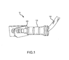
- Hose attachment system 10 may comprise hose guide 100.
- Hose guide 100 may be coupled to hose 110.
- Hose 110 is coupled to hose fittings 120.
- hose 110 may be a hydraulic hose.
- Manufacturer specifications for hose 110 may recommend that hose 110 not substantially bend within a defined distance of hose fittings 120.
- specifications may recommend that hose 110 remains substantially straight within one diameter of hose fittings 120. In other words, if hose 110 has a diameter of one inch, hose 110 must remain substantially straight within one inch of hose fittings 120.
- hose 110 must remain substantially straight within one-half of the diameter of hose 110, or within two diameters of hose 110. In various embodiments, hose 110 may be defined as substantially straight if hose 110 bends less than one degree, or less than five degrees.
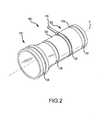
- Hose guide 100 may comprise a straight section 102 and a bell section 104.
- Straight section 102 may be configured to keep a hose 110 substantially straight within straight section 102.
- a radially outer outside diameter of outer surface 106 of hose guide 100 measured at straight section 102 may be of constant and/or substantially constant radius as one travels axially along axis A in straight section 102.
- a radially outer outside diameter of outer surface 106 of hose guide 100 measured at bell section 104 may be of varying and/or variable radius as one travels axially along axis A in bell section 104.
- Bell section 104 may be configured to allow hose 110 to bend within the interior space of bell section 104.
- an outside diameter of hose guide 100 measured at bell section 104 may be larger than an outside diameter of hose guide 100 measured at straight section 102.
- the outside diameter measured at bell section 104 may be substantially the same as the outside diameter measured at straight section 102, or the outside diameter measured at bell section 104 may be less than the outside diameter measured at straight section 102.
- the outside diameter measured at bell section 104 may vary as one travels axially along axis A in bell section 104. In various embodiments, the outside diameter at bell section 104 is larger than the outside diameter at straight section 102.
- Hose guide 100 may further comprise one or more grooves 108 in an outer surface 106 of hose guide 100.
- Grooves 108 may be located in straight section 102, bell section 104, or in both straight section 102 and bell section 104.
- Fastening devices 113 such as wire ties or hose clamps, may be secured in grooves 108 in order to secure multiple pieces of hose guide 100 together.
- Groove walls 109 may prevent translational movement of fastening devices 113 when in place.
- hose guide 100 may comprise plastic.
- Hose guide 100 may be formed in a mold, such as an injection mold.
- hose guide 100 may comprise any material capable of preventing hose 110 from bending, such as steel, aluminum, carbon composites, copper, rubber, etc.
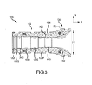
- Hose guide 100 may comprise a plurality of hose fitting stages 130A, 130B, 130C, 130D, 130E, and 130F. Hose fitting stages 130A, 130B, 130C, 130D, 130E, and 130F may each have a different radially inner inside diameter. However, in various embodiments, two or more hose fitting stages 130A, 130B, 130C, 130D, 130E, and 130F may comprise substantially the same diameter.
- hose fitting stages 130A, 130B, 130C, 130D, 130E, and 130F may vary based on the intended hose and fittings to be used with hose guide 100.
- hose guide 100 may comprise one hose fitting stage.
- hose guide may comprise two, three, four, five, six, or more hose fitting stages.
- Hose guide 100 may further comprise straight hose stage 140 directly coupled to bell section 104 and axially located between bell section 104 and hose fitting stage 130F.
- straight hose stage 140 hose guide 100 may prevent bending of hose 110 axially located within straight hose stage 140.
- a length of straight hose stage 140 may be selected based on specifications for hose 110 describing a minimum distance from the hose fittings that hose 110 must remain substantially straight. For example, specifications may recommend that hose 110 remain substantially straight within one inch of hose fittings 120.
- straight hose stage 140 may be at least one inch long in such embodiments.
- a diameter of straight hose stage 140 may be substantially equal to a diameter of hose 110.
- the diameter of straight hose stage 140 may be slightly greater than the diameter of hose 110, such as 1-2% greater or 5-10% greater, in order to ensure that hose guide 100 may fit around hose 110.
- An interior surface 142 of straight hose stage 140 may contact hose 110 to prevent hose 110 from bending when positioned in straight hose stage 140.
- Hose guide 100 may further comprise bell stage 150.
- bell stage 150 an inside diameter D1 of hose guide 100 may increase with an increase in the x-direction away from straight section 102.
- a profile of bell stage 150 may be curved with a radius R. Radius R may correspond to a minimum bend radius for hose 110. Thus, bell stage 150 may allow hose 110 to bend, but may prevent hose 110 from bending at a radius less than radius R.
- hose guide 100 may comprise a two-piece construction. However, in various embodiments, hose guide 100 may comprise a single piece, or three or more pieces. In various embodiments, hose guide 100 may comprise a single piece which may be formed around a hose at the time that fittings are attached to the hose.
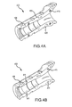
- First piece 400 may comprise alignment pegs 410. Alignment pegs 410 may extend from mating surfaces 420 of first piece 400. Alignment pegs 410 may be configured to align with alignment holes 411 on second piece 450.
- Alignment pegs 410 may be inserted into alignment holes 411, thus aligning first piece 400 with second piece 450.
- Fasteners may be placed in grooves 108 to secure first piece 400 to second piece 450.
- first piece 400 may be secured to second piece 450 using screws, bolts, snaps, clips, an adhesive, or any other method for coupling first piece 400 to second piece 450.
- First piece 400 and second piece 450 may be coupled together around hose 110 and hose fittings 120.
- First piece 400 and second piece 450 may mate together to form an inner cavity.
- the inner cavity may comprise hose fitting stages 130A through 130F, straight hose stage 140, and bell stage 150 as described with reference to FIG. 3 .
- First piece 500 may comprise bell section 502, and straight section 504.
- First piece 500 may further comprise hose fitting stages 530A, 530B, 530C, and 530D.
- first piece 500 comprises four hose fitting stages.
- first piece 500 may comprise any number of hose fitting stages.
- First piece 500 may further comprise straight hose stage 540 directly coupled to bell section 502 and axially located between bell section 502 and hose fitting stage 530D.
- Hose 510 may comprise free section 512, constrained section 514, and fittings 516A, 516B, 516C, 516D, 516E, 516F, and 516G.
- Free section 512 may be permitted to bend within bell section 502.
- bell section 502 may prevent free section 512 from bending at a radius less than a radius R2 of bell section 502.
- Straight section 504 may prevent constrained section 514 from substantially bending.
- straight section 504 may prevent damage to hose 510 at constrained section 514, where hose 510 may be susceptible to damage from bending.
- Hose fittings 516A, 516B, 516C, 516D, 516E, 516F, and 516G may comprise any type of hose fittings which may be attached to a hose.
- hose fittings 516A, 516B, 516C, 516D, 516E, 516F, and 516G may be swaged onto hose 510.
- hose fittings 516A, 516B, 516C, 516D, 516E, 516F, and 516G may be located within first piece 500, and at least one of hose fittings 516A, 516B, 516C, 516D, 516E, 516F, and 516G may be located axially exterior of first piece 500.
- Hose fitting 516A may be located in hose fitting stage 530A
- hose fitting 516B may be located in hose fitting stage 530B
- hose fitting 516C may be located in hose fitting stages 530C and 530D.
- Hose fitting stages 530A, 530B, 530C, and 530D may be designed such that first piece 500 may accommodate a plurality of hose fitting types.
- different diameters of the various hose fitting stages 530A, 530B, 530C, and 530D may prevent translational movement along axis B of hose 510 within first piece 500.
- hose fitting stages 530A and 530C may have a diameter less than hose fitting stage 530B and hose fitting 516B.
- hose fitting stages 530A and 530C may contact hose fitting 516B and prevent translational movement of hose 510 within first piece 500.
- Hose guide 600 may comprise first piece 620 and second piece 630.
- An interior section 640 may be similar to that of hose guide 100, as described with reference to FIG. 3 .
- bolt lugs 610 may be coupled to first piece 620 and second piece 630.
- bolt lugs 610 may be integrally formed with first piece 620 and second piece 630.
- bolt lug mating surfaces 614 may be flush with first piece mating surfaces 624.
- first piece 620 may further comprise alignment holes 650, which may align with corresponding alignment pegs on second piece 630 in order to assist with aligning first piece 620 and second piece 630.
- bolt lugs 610 may define bolt holes 612.
- a fastening device such as a bolt 660 may be inserted through a bolt hole 612 on first piece 620 and through a corresponding bolt hole 612 on second piece 630.
- first piece 620 and second piece 630 may be coupled around a hose using bolts.
- additional fastening devices such as zip ties or wires may be used to couple first piece 620 to second piece 630.
- references to "various embodiments”, “one embodiment”, “an embodiment”, “an example embodiment”, etc. indicate that the embodiment described may include a particular feature, structure, or characteristic, but every embodiment may not necessarily include the particular feature, structure, or characteristic. Moreover, such phrases are not necessarily referring to the same embodiment. Further, when a particular feature, structure, or characteristic is described in connection with an embodiment, it is submitted that it is within the knowledge of one skilled in the art to affect such feature, structure, or characteristic in connection with other embodiments whether or not explicitly described. After reading the description, it will be apparent to one skilled in the relevant art(s) how to implement the disclosure in alternative embodiments.
Landscapes
- Engineering & Computer Science (AREA)
- General Engineering & Computer Science (AREA)
- Mechanical Engineering (AREA)
- Supports For Pipes And Cables (AREA)
Abstract
Description
- The present disclosure relates to hydraulic hoses, and more particularly, to hydraulic hose fittings.
- Hydraulic hoses have many applications. Hydraulic hoses may transmit hydraulic fluid under pressure to cause hydraulic machinery to perform work. Hydraulic hoses may be used instead of rigid pipes or tubes where flexibility is required or beneficial. The hydraulic hoses may have steel fittings swaged on the ends. The weakest part of the hydraulic hose may be at the connection between the hose and the steel fittings. In response to the hydraulic hose bending within a specified distance of the fittings, or bending at a radius less than a minimum bend radius, the hose may rupture or leak, causing the hydraulic system to fail.
- In various embodiments, a hose guide may comprise a straight section and a bell section. The straight section may comprise a plurality of hose fitting stages. Each hose fitting stage may have a different diameter. The bell section may comprise a curved inner profile. The curved inner profile may correspond to a minimum bend radius of a hose. The hose guide may further comprise a straight hose stage which prevents the hose from bending.
- In various embodiments, a hose guide may comprise a first piece coupled to a second piece. The first piece and the second piece may define an inner cavity. The inner cavity may comprise a hose fitting stage, a straight hose stage, and a bell stage. A diameter of the bell stage may increase as a distance from the hose fitting stage increases.
- In various embodiments, a hose attachment system may include a hose with a minimum bend radius, a fitting coupled to the hose, and a hose guide. The hose guide may comprise a hose fitting stage located around the fitting, a straight hose stage which prevents the hose from bending, and a bell stage. The bell stage may have an inner profile with a radius greater than or equal to the minimum bend radius of the hose.
- The subject matter of the present disclosure is particularly pointed out and distinctly claimed in the concluding portion of the specification. A more complete understanding of the present disclosure, however, may best be obtained by referring to the detailed description and claims when considered in connection with the drawing figures, wherein like numerals denote like elements.
-
FIG. 1 illustrates, in accordance with various embodiments, a hose attachment system; -
FIG. 2 illustrates, in accordance with various embodiments, a perspective view of a hose guide; -
FIG. 3 illustrates, in accordance with various embodiments, a side view of a first piece of a hose guide; -
FIGs. 4A-4B illustrate, in accordance with various embodiments, a perspective view of a first piece and a second piece of a hose guide; -
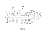
FIG. 5 illustrates a hose in a piece of a hose guide; and -
FIG. 6 illustrates, in accordance with various embodiments, a perspective view of a first piece and a second piece of a hose guide with bolt lugs. - The detailed description of exemplary embodiments herein makes reference to the accompanying drawings, which show exemplary embodiments by way of illustration and their best mode. While these exemplary embodiments are described in sufficient detail to enable those skilled in the art to practice the inventions, it should be understood that other embodiments may be realized and that logical, chemical and mechanical changes may be made without departing from the scope of the inventions. Thus, the detailed description herein is presented for purposes of illustration only and not of limitation. For example, the steps recited in any of the method or process descriptions may be executed in any order and are not necessarily limited to the order presented. Furthermore, any reference to singular includes plural embodiments, and any reference to more than one component or step may include a singular embodiment or step. Also, any reference to attached, fixed, connected or the like may include permanent, removable, temporary, partial, full and/or any other possible attachment option. Additionally, any reference to without contact (or similar phrases) may also include reduced contact or minimal contact.
- Referring to
FIG. 1 , ahose attachment system 10 is illustrated according to various embodiments.Hose attachment system 10 may comprisehose guide 100.Hose guide 100 may be coupled tohose 110.Hose 110 is coupled tohose fittings 120. In various embodiments,hose 110 may be a hydraulic hose. Manufacturer specifications forhose 110 may recommend thathose 110 not substantially bend within a defined distance ofhose fittings 120. For example, in various embodiments, specifications may recommend thathose 110 remains substantially straight within one diameter ofhose fittings 120. In other words, ifhose 110 has a diameter of one inch,hose 110 must remain substantially straight within one inch ofhose fittings 120. In various embodiments,hose 110 must remain substantially straight within one-half of the diameter ofhose 110, or within two diameters ofhose 110. In various embodiments,hose 110 may be defined as substantially straight ifhose 110 bends less than one degree, or less than five degrees. - Referring to
FIG. 2 , a perspective view of ahose guide 100 is illustrated according to various embodiments.Hose guide 100 may comprise astraight section 102 and abell section 104.Straight section 102 may be configured to keep ahose 110 substantially straight withinstraight section 102. In various embodiments, a radially outer outside diameter ofouter surface 106 ofhose guide 100 measured atstraight section 102 may be of constant and/or substantially constant radius as one travels axially along axis A instraight section 102. In various embodiments, a radially outer outside diameter ofouter surface 106 ofhose guide 100 measured atbell section 104 may be of varying and/or variable radius as one travels axially along axis A inbell section 104.Bell section 104 may be configured to allowhose 110 to bend within the interior space ofbell section 104. As illustrated, an outside diameter ofhose guide 100 measured atbell section 104 may be larger than an outside diameter ofhose guide 100 measured atstraight section 102. However, in various embodiments, the outside diameter measured atbell section 104 may be substantially the same as the outside diameter measured atstraight section 102, or the outside diameter measured atbell section 104 may be less than the outside diameter measured atstraight section 102. The outside diameter measured atbell section 104 may vary as one travels axially along axis A inbell section 104. In various embodiments, the outside diameter atbell section 104 is larger than the outside diameter atstraight section 102. -
Hose guide 100 may further comprise one ormore grooves 108 in anouter surface 106 ofhose guide 100.Grooves 108 may be located instraight section 102,bell section 104, or in bothstraight section 102 andbell section 104. Fasteningdevices 113, such as wire ties or hose clamps, may be secured ingrooves 108 in order to secure multiple pieces ofhose guide 100 together.Groove walls 109 may prevent translational movement of fasteningdevices 113 when in place. - In various embodiments,
hose guide 100 may comprise plastic.Hose guide 100 may be formed in a mold, such as an injection mold. However,hose guide 100 may comprise any material capable of preventinghose 110 from bending, such as steel, aluminum, carbon composites, copper, rubber, etc. - Referring to
FIG. 3 , a side view of afirst piece 300 ofhose guide 100 is illustrated according to various embodiments.First piece 300 comprisesstraight section 102,bell section 104, andgrooves 108.Hose guide 100 may comprise a plurality of hosefitting stages fitting stages fitting stages hose guide 100. For example, in various embodiments,hose guide 100 may comprise one hose fitting stage. However, in various embodiments, hose guide may comprise two, three, four, five, six, or more hose fitting stages. -
Hose guide 100 may further comprisestraight hose stage 140 directly coupled tobell section 104 and axially located betweenbell section 104 and hosefitting stage 130F. Instraight hose stage 140,hose guide 100 may prevent bending ofhose 110 axially located withinstraight hose stage 140. A length ofstraight hose stage 140 may be selected based on specifications forhose 110 describing a minimum distance from the hose fittings thathose 110 must remain substantially straight. For example, specifications may recommend thathose 110 remain substantially straight within one inch ofhose fittings 120. Thus,straight hose stage 140 may be at least one inch long in such embodiments. In various embodiments, a diameter ofstraight hose stage 140 may be substantially equal to a diameter ofhose 110. The diameter ofstraight hose stage 140 may be slightly greater than the diameter ofhose 110, such as 1-2% greater or 5-10% greater, in order to ensure thathose guide 100 may fit aroundhose 110. Aninterior surface 142 ofstraight hose stage 140 may contacthose 110 to preventhose 110 from bending when positioned instraight hose stage 140. -
Hose guide 100 may further comprisebell stage 150. Inbell stage 150, an inside diameter D1 ofhose guide 100 may increase with an increase in the x-direction away fromstraight section 102. A profile ofbell stage 150 may be curved with a radius R. Radius R may correspond to a minimum bend radius forhose 110. Thus,bell stage 150 may allowhose 110 to bend, but may preventhose 110 from bending at a radius less than radius R. - Referring to
FIGs. 4A and 4B , afirst piece 400 andsecond piece 450 ofhose guide 100 is illustrated according to various embodiments. In various embodiments,hose guide 100 may comprise a two-piece construction. However, in various embodiments,hose guide 100 may comprise a single piece, or three or more pieces. In various embodiments,hose guide 100 may comprise a single piece which may be formed around a hose at the time that fittings are attached to the hose.First piece 400 may comprise alignment pegs 410. Alignment pegs 410 may extend frommating surfaces 420 offirst piece 400. Alignment pegs 410 may be configured to align withalignment holes 411 onsecond piece 450. Alignment pegs 410 may be inserted intoalignment holes 411, thus aligningfirst piece 400 withsecond piece 450. Fasteners may be placed ingrooves 108 to securefirst piece 400 tosecond piece 450. However, in various embodiments,first piece 400 may be secured tosecond piece 450 using screws, bolts, snaps, clips, an adhesive, or any other method for couplingfirst piece 400 tosecond piece 450.First piece 400 andsecond piece 450 may be coupled together aroundhose 110 andhose fittings 120.First piece 400 andsecond piece 450 may mate together to form an inner cavity. The inner cavity may comprise hosefitting stages 130A through 130F,straight hose stage 140, andbell stage 150 as described with reference toFIG. 3 . - Referring to
FIG. 5 , ahose 510 is illustrated located within afirst piece 500 of a hose guide.First piece 500 may comprisebell section 502, andstraight section 504.First piece 500 may further comprise hosefitting stages first piece 500 comprises four hose fitting stages. However, as previously described, in various embodimentsfirst piece 500 may comprise any number of hose fitting stages.First piece 500 may further comprisestraight hose stage 540 directly coupled tobell section 502 and axially located betweenbell section 502 and hosefitting stage 530D. -
Hose 510 may comprisefree section 512, constrainedsection 514, andfittings Free section 512 may be permitted to bend withinbell section 502. However,bell section 502 may preventfree section 512 from bending at a radius less than a radius R2 ofbell section 502.Straight section 504 may preventconstrained section 514 from substantially bending. Thus,straight section 504 may prevent damage tohose 510 atconstrained section 514, wherehose 510 may be susceptible to damage from bending.Hose fittings hose fittings hose 510. In various embodiments, at least one ofhose fittings first piece 500, and at least one ofhose fittings first piece 500. Hose fitting 516A may be located in hosefitting stage 530A, hose fitting 516B may be located in hosefitting stage 530B, and hose fitting 516C may be located in hosefitting stages first piece 500 may accommodate a plurality of hose fitting types. In various embodiments, different diameters of the various hosefitting stages hose 510 withinfirst piece 500. For example, hosefitting stages fitting stage 530B and hose fitting 516B. Thus, hosefitting stages hose 510 withinfirst piece 500. - Referring to
FIG. 6 , a perspective view of ahose guide 600 with fastening members such as bolt lugs 610 is illustrated according to various embodiments.Hose guide 600 may comprisefirst piece 620 andsecond piece 630. Aninterior section 640 may be similar to that ofhose guide 100, as described with reference toFIG. 3 . In various embodiments, bolt lugs 610 may be coupled tofirst piece 620 andsecond piece 630. In various embodiments, bolt lugs 610 may be integrally formed withfirst piece 620 andsecond piece 630. In various embodiments, bolt lug mating surfaces 614 may be flush with first piece mating surfaces 624. In various embodiments,first piece 620 may further comprisealignment holes 650, which may align with corresponding alignment pegs onsecond piece 630 in order to assist with aligningfirst piece 620 andsecond piece 630. - In various embodiments, bolt lugs 610 may define bolt holes 612. A fastening device such as a
bolt 660 may be inserted through abolt hole 612 onfirst piece 620 and through acorresponding bolt hole 612 onsecond piece 630. Thus,first piece 620 andsecond piece 630 may be coupled around a hose using bolts. In various embodiments, additional fastening devices, such as zip ties or wires may be used to couplefirst piece 620 tosecond piece 630. - Benefits, other advantages, and solutions to problems have been described herein with regard to specific embodiments. Furthermore, the connecting lines shown in the various figures contained herein are intended to represent exemplary functional relationships and/or physical couplings between the various elements. It should be noted that many alternative or additional functional relationships or physical connections may be present in a practical system. However, the benefits, advantages, solutions to problems, and any elements that may cause any benefit, advantage, or solution to occur or become more pronounced are not to be construed as critical, required, or essential features or elements of the inventions. The scope of the inventions is accordingly to be limited by nothing other than the appended claims, in which reference to an element in the singular is not intended to mean "one and only one" unless explicitly so stated, but rather "one or more." Moreover, where a phrase similar to "at least one of A, B, or C" is used in the claims, it is intended that the phrase be interpreted to mean that A alone may be present in an embodiment, B alone may be present in an embodiment, C alone may be present in an embodiment, or that any combination of the elements A, B and C may be present in a single embodiment; for example, A and B, A and C, B and C, or A and B and C.
- Systems, methods and apparatus are provided herein. In the detailed description herein, references to "various embodiments", "one embodiment", "an embodiment", "an example embodiment", etc., indicate that the embodiment described may include a particular feature, structure, or characteristic, but every embodiment may not necessarily include the particular feature, structure, or characteristic. Moreover, such phrases are not necessarily referring to the same embodiment. Further, when a particular feature, structure, or characteristic is described in connection with an embodiment, it is submitted that it is within the knowledge of one skilled in the art to affect such feature, structure, or characteristic in connection with other embodiments whether or not explicitly described. After reading the description, it will be apparent to one skilled in the relevant art(s) how to implement the disclosure in alternative embodiments.
- Furthermore, no element, component, or method step in the present disclosure is intended to be dedicated to the public regardless of whether the element, component, or method step is explicitly recited in the claims. No claim element herein is to be construed under the provisions of 35 U.S.C. 112, sixth paragraph, unless the element is expressly recited using the phrase "means for." As used herein, the terms "comprises", "comprising", or any other variation thereof, are intended to cover a non-exclusive inclusion, such that a process, method, article, or apparatus that comprises a list of elements does not include only those elements but may include other elements not expressly listed or inherent to such process, method, article, or apparatus.
Claims (15)
- A hose guide (100) comprising:a straight section (102;504) comprising at least one hose fitting stage (130A-130F;530A-530D); anda bell section (104;502) directly coupled to and axially aligned with the straight section (102;504), the bell section (104;502) comprising a curved inner profile, wherein the straight section (102;504) is configured to prevent a hose (110) from bending within the straight section (102;504).
- The hose guide of claim 1, wherein the at least one hose fitting stage (130A-130F;530A-530D) comprises a plurality of hose fitting stages (130A-130F;530A-530D).
- The hose guide of claim 2, wherein an inside diameter of a first hose fitting stage of the plurality of hose fitting stages (130A-130F;530A-530D) is greater than an inside diameter of a second hose fitting stage of the plurality of hose fitting stages (130A-130F;530A-530D).
- The hose guide of claim 1, 2 or 3, further comprising one or more grooves (108) in an outer surface of the hose guide (100).
- The hose guide of claim 4, further comprising one or more fasteners located in the one or more grooves (108).
- The hose guide of any preceding claim, wherein the hose guide (100) comprises a first piece (400;620) including a first fastening member (410;610), and a second piece (450;630) including a second fastening member (411;610), and wherein the first piece (400;620) and the second piece (450;630) are configured to be coupled together with a fastening device (113;612;660) coupling the first and second fastening members (410;411;610).
- The hose guide of any of claims 1 to 5, further comprising a first piece (400;620) and a second piece (450;630), wherein one or more fasteners (113;612;660) couple the first piece (400;620) to the second piece (450;630), and, wherein, optionally the first piece (400;620) comprises an alignment peg (410); and, wherein, further optionally, the alignment peg (410) is located within an alignment hole (411) in the second piece (450;630).
- The hose guide of any preceding claim, wherein the curved inner profile corresponds to a minimum bend radius of a hose (110).
- The hose guide of any preceding claim, wherein an outside diameter of the bell section (104;502) is greater than an outside diameter of the straight section (102;504).
- A hose guide (100) comprising:a first piece (400;620); anda second piece (450;630) coupled to the first piece (400;620), wherein the first piece (400;620) and the second piece (450;630) form an inner cavity comprising at least one hose fitting stage (130A-130F;530A-530D), a straight hose stage (140;540), and a bell stage (150).
- The hose guide of claim 10, wherein an inside diameter of the bell stage (150) increases as a distance from the at least one hose fitting stage (130A-130F;530A-530D) increases.
- The hose guide of claim 10 or 11, further comprising a fastener (113) located in a groove (108) in the first piece (400;620) and the second piece (450;630); and/or wherein the first piece (400;620) comprises an alignment peg (410) located within an alignment hole (411) in the second piece (450;630); and/or wherein a radius of an inner profile of the bell stage (150) is configured to protect a free portion of a hose (110) from bending at a radius less than a radius of the bell stage (150).
- The hose guide of any of claims 10 to 12, wherein the at least one hose fitting stage (130A-130F;530A-530D) further comprises a plurality of hose fitting stages (130A-130F;530A-530D), wherein each hose fitting stage (130A-130F;530A-530D) in the plurality of hose fitting stages (130A-130F;530A-530D) comprises a different diameter.
- A hose attachment system comprising:a hose (110) with a minimum bend radius;a fitting (120) coupled to the hose (110); anda hose guide (100) comprising:a hose fitting stage (130A-130F;530A-530D) located around the fitting (120);a straight hose stage (140;540) configured to prevent the hose (110) from bending; anda bell stage (150) comprising an inner profile with a radius greater than or equal to the minimum bend radius.
- The hose attachment system of claim 14, further comprising a fastener (113) located in a groove (108) in an outer surface of the hose guide (100); and/or wherein the hose guide (100) comprises a first piece (400;620) and a second piece (450;630) coupled around the hose (110) and the fitting (120).
Applications Claiming Priority (1)
| Application Number | Priority Date | Filing Date | Title |
|---|---|---|---|
| US13/957,368 US9651181B2 (en) | 2013-08-01 | 2013-08-01 | Hydraulic hose guide |
Publications (2)
| Publication Number | Publication Date |
|---|---|
| EP2833044A1 true EP2833044A1 (en) | 2015-02-04 |
| EP2833044B1 EP2833044B1 (en) | 2018-12-26 |
Family
ID=50842152
Family Applications (1)
| Application Number | Title | Priority Date | Filing Date |
|---|---|---|---|
| EP14170817.2A Active EP2833044B1 (en) | 2013-08-01 | 2014-06-02 | Hydraulic hose guide |
Country Status (2)
| Country | Link |
|---|---|
| US (1) | US9651181B2 (en) |
| EP (1) | EP2833044B1 (en) |
Cited By (1)
| Publication number | Priority date | Publication date | Assignee | Title |
|---|---|---|---|---|
| USD940974S1 (en) * | 2018-05-31 | 2022-01-11 | Camco Manufacturing, Llc | Swivel stick adapter |
Families Citing this family (8)
| Publication number | Priority date | Publication date | Assignee | Title |
|---|---|---|---|---|
| WO2017086943A1 (en) * | 2015-11-18 | 2017-05-26 | Halliburton Energy Services, Inc. | Segmented bend-limiter for slickline rope sockets and cable-heads |
| JP6416743B2 (en) * | 2015-12-11 | 2018-10-31 | 日本フルハーフ株式会社 | Hydraulic hose connection structure |
| GB2550933B (en) * | 2016-06-01 | 2019-01-16 | Taylor Kerr Couplings Ltd | Self-aligning pipe coupling |
| CN106151771B (en) * | 2016-07-04 | 2018-04-03 | 燕山大学 | A kind of corrugated flexible metal tube pipe end protector |
| AU201713590S (en) * | 2016-12-16 | 2017-06-26 | Rehau Ag & Co | Component for fluid distribution equipment |
| US10662948B2 (en) * | 2017-06-13 | 2020-05-26 | HELLA GmbH & Co. KGaA | Expansion chamber for a brake boost vacuum pump |
| US10837158B2 (en) * | 2018-02-07 | 2020-11-17 | Manitou Equipment America, Llc | Loader, operator seat assembly with integrated, non-electronic hydraulic pilot valves |
| US12562558B2 (en) * | 2024-01-25 | 2026-02-24 | Panduit Corp. | Segmented bend restrictor system with full disassembly capability |
Citations (4)
| Publication number | Priority date | Publication date | Assignee | Title |
|---|---|---|---|---|
| US1844023A (en) * | 1929-01-02 | 1932-02-09 | Cash A W Co | Hose clamp |
| US2295830A (en) * | 1940-11-26 | 1942-09-15 | Scovill Manufacturing Co | Hose coupling |
| GB643615A (en) * | 1948-05-05 | 1950-09-20 | Weeks & Son Ltd W | Improvements in hose clamps |
| DE3619233A1 (en) * | 1985-06-11 | 1986-12-11 | Luisa Polaveno Brescia Epis | Covering device for connections, in particular of heating radiators and the like |
Family Cites Families (4)
| Publication number | Priority date | Publication date | Assignee | Title |
|---|---|---|---|---|
| US1970050A (en) * | 1932-09-03 | 1934-08-14 | Ferdinand A Mathey | Hose coupling |
| US5853200A (en) * | 1996-04-15 | 1998-12-29 | Gary A. Zieres | Hose coupling boot |
| GB9703144D0 (en) * | 1997-02-14 | 1997-04-02 | Tyrer Andrew C R | Bend stiffeners |
| US9163463B2 (en) * | 2011-06-01 | 2015-10-20 | Deep Down, Inc. | Bend limiting stiffener and related methods |
-
2013
- 2013-08-01 US US13/957,368 patent/US9651181B2/en active Active
-
2014
- 2014-06-02 EP EP14170817.2A patent/EP2833044B1/en active Active
Patent Citations (4)
| Publication number | Priority date | Publication date | Assignee | Title |
|---|---|---|---|---|
| US1844023A (en) * | 1929-01-02 | 1932-02-09 | Cash A W Co | Hose clamp |
| US2295830A (en) * | 1940-11-26 | 1942-09-15 | Scovill Manufacturing Co | Hose coupling |
| GB643615A (en) * | 1948-05-05 | 1950-09-20 | Weeks & Son Ltd W | Improvements in hose clamps |
| DE3619233A1 (en) * | 1985-06-11 | 1986-12-11 | Luisa Polaveno Brescia Epis | Covering device for connections, in particular of heating radiators and the like |
Cited By (1)
| Publication number | Priority date | Publication date | Assignee | Title |
|---|---|---|---|---|
| USD940974S1 (en) * | 2018-05-31 | 2022-01-11 | Camco Manufacturing, Llc | Swivel stick adapter |
Also Published As
| Publication number | Publication date |
|---|---|
| US20150035271A1 (en) | 2015-02-05 |
| EP2833044B1 (en) | 2018-12-26 |
| US9651181B2 (en) | 2017-05-16 |
Similar Documents
| Publication | Publication Date | Title |
|---|---|---|
| EP2833044B1 (en) | Hydraulic hose guide | |
| CN102762907B (en) | Couplings with angularly oriented key surfaces | |
| EP2923134B1 (en) | Sealing system | |
| CN105518366B (en) | Quick lock tube securement system | |
| SE443436B (en) | fluid connector | |
| CN108139002B (en) | Connection clamping device | |
| KR101408807B1 (en) | Bellows for vacuum piping, and combined structure of bellows and pipe | |
| US20120217743A1 (en) | Pipe coupling assembly with sleeve locking tabs and associated methods | |
| US20190063644A1 (en) | Lock band and method of manufacturing | |
| CN104662352B (en) | Ear clip | |
| AU2009221456B2 (en) | Connecting piece for a clamping connector | |
| GB2544075A (en) | Improvements relating to bend restrictors | |
| US20170107770A1 (en) | Interface | |
| EP3306165B1 (en) | Threaded retainer | |
| EP3440392B1 (en) | Guide apparatus | |
| CA3037479C (en) | Clip-based non-metallic fittings for attachment of flexible metallic conduit | |
| KR20110011340U (en) | Connecting Clamp for Preventing Separation of Hose Connection Part | |
| US11939822B2 (en) | Control line protector assembly | |
| JP5400367B2 (en) | Electric fusion joint | |
| CN103133802A (en) | Anti-rotation cable restraint for connecting flexible ducts | |
| US20230344207A1 (en) | Conduit fitting | |
| CN109716607B (en) | Pin-based non-metallic fittings for attachment of flexible metal conduits | |
| US20050212294A1 (en) | Toggle locked coupling | |
| CN216132826U (en) | Test fixture | |
| JP5841496B2 (en) | Sheath tube reinforcing member and lotus tube |
Legal Events
| Date | Code | Title | Description |
|---|---|---|---|
| 17P | Request for examination filed |
Effective date: 20140602 |
|
| AK | Designated contracting states |
Kind code of ref document: A1 Designated state(s): AL AT BE BG CH CY CZ DE DK EE ES FI FR GB GR HR HU IE IS IT LI LT LU LV MC MK MT NL NO PL PT RO RS SE SI SK SM TR |
|
| AX | Request for extension of the european patent |
Extension state: BA ME |
|
| PUAI | Public reference made under article 153(3) epc to a published international application that has entered the european phase |
Free format text: ORIGINAL CODE: 0009012 |
|
| R17P | Request for examination filed (corrected) |
Effective date: 20150803 |
|
| RBV | Designated contracting states (corrected) |
Designated state(s): AL AT BE BG CH CY CZ DE DK EE ES FI FR GB GR HR HU IE IS IT LI LT LU LV MC MK MT NL NO PL PT RO RS SE SI SK SM TR |
|
| STAA | Information on the status of an ep patent application or granted ep patent |
Free format text: STATUS: EXAMINATION IS IN PROGRESS |
|
| 17Q | First examination report despatched |
Effective date: 20171013 |
|
| GRAP | Despatch of communication of intention to grant a patent |
Free format text: ORIGINAL CODE: EPIDOSNIGR1 |
|
| STAA | Information on the status of an ep patent application or granted ep patent |
Free format text: STATUS: GRANT OF PATENT IS INTENDED |
|
| INTG | Intention to grant announced |
Effective date: 20180720 |
|
| GRAS | Grant fee paid |
Free format text: ORIGINAL CODE: EPIDOSNIGR3 |
|
| GRAA | (expected) grant |
Free format text: ORIGINAL CODE: 0009210 |
|
| STAA | Information on the status of an ep patent application or granted ep patent |
Free format text: STATUS: THE PATENT HAS BEEN GRANTED |
|
| AK | Designated contracting states |
Kind code of ref document: B1 Designated state(s): AL AT BE BG CH CY CZ DE DK EE ES FI FR GB GR HR HU IE IS IT LI LT LU LV MC MK MT NL NO PL PT RO RS SE SI SK SM TR |
|
| REG | Reference to a national code |
Ref country code: GB Ref legal event code: FG4D |
|
| REG | Reference to a national code |
Ref country code: CH Ref legal event code: EP |
|
| REG | Reference to a national code |
Ref country code: AT Ref legal event code: REF Ref document number: 1081885 Country of ref document: AT Kind code of ref document: T Effective date: 20190115 |
|
| REG | Reference to a national code |
Ref country code: DE Ref legal event code: R096 Ref document number: 602014038494 Country of ref document: DE |
|
| REG | Reference to a national code |
Ref country code: IE Ref legal event code: FG4D |
|
| PG25 | Lapsed in a contracting state [announced via postgrant information from national office to epo] |
Ref country code: FI Free format text: LAPSE BECAUSE OF FAILURE TO SUBMIT A TRANSLATION OF THE DESCRIPTION OR TO PAY THE FEE WITHIN THE PRESCRIBED TIME-LIMIT Effective date: 20181226 Ref country code: NO Free format text: LAPSE BECAUSE OF FAILURE TO SUBMIT A TRANSLATION OF THE DESCRIPTION OR TO PAY THE FEE WITHIN THE PRESCRIBED TIME-LIMIT Effective date: 20190326 Ref country code: HR Free format text: LAPSE BECAUSE OF FAILURE TO SUBMIT A TRANSLATION OF THE DESCRIPTION OR TO PAY THE FEE WITHIN THE PRESCRIBED TIME-LIMIT Effective date: 20181226 Ref country code: LT Free format text: LAPSE BECAUSE OF FAILURE TO SUBMIT A TRANSLATION OF THE DESCRIPTION OR TO PAY THE FEE WITHIN THE PRESCRIBED TIME-LIMIT Effective date: 20181226 Ref country code: BG Free format text: LAPSE BECAUSE OF FAILURE TO SUBMIT A TRANSLATION OF THE DESCRIPTION OR TO PAY THE FEE WITHIN THE PRESCRIBED TIME-LIMIT Effective date: 20190326 Ref country code: LV Free format text: LAPSE BECAUSE OF FAILURE TO SUBMIT A TRANSLATION OF THE DESCRIPTION OR TO PAY THE FEE WITHIN THE PRESCRIBED TIME-LIMIT Effective date: 20181226 |
|
| REG | Reference to a national code |
Ref country code: NL Ref legal event code: MP Effective date: 20181226 |
|
| REG | Reference to a national code |
Ref country code: LT Ref legal event code: MG4D |
|
| PG25 | Lapsed in a contracting state [announced via postgrant information from national office to epo] |
Ref country code: AL Free format text: LAPSE BECAUSE OF FAILURE TO SUBMIT A TRANSLATION OF THE DESCRIPTION OR TO PAY THE FEE WITHIN THE PRESCRIBED TIME-LIMIT Effective date: 20181226 Ref country code: SE Free format text: LAPSE BECAUSE OF FAILURE TO SUBMIT A TRANSLATION OF THE DESCRIPTION OR TO PAY THE FEE WITHIN THE PRESCRIBED TIME-LIMIT Effective date: 20181226 Ref country code: RS Free format text: LAPSE BECAUSE OF FAILURE TO SUBMIT A TRANSLATION OF THE DESCRIPTION OR TO PAY THE FEE WITHIN THE PRESCRIBED TIME-LIMIT Effective date: 20181226 Ref country code: GR Free format text: LAPSE BECAUSE OF FAILURE TO SUBMIT A TRANSLATION OF THE DESCRIPTION OR TO PAY THE FEE WITHIN THE PRESCRIBED TIME-LIMIT Effective date: 20190327 |
|
| REG | Reference to a national code |
Ref country code: AT Ref legal event code: MK05 Ref document number: 1081885 Country of ref document: AT Kind code of ref document: T Effective date: 20181226 |
|
| PG25 | Lapsed in a contracting state [announced via postgrant information from national office to epo] |
Ref country code: NL Free format text: LAPSE BECAUSE OF FAILURE TO SUBMIT A TRANSLATION OF THE DESCRIPTION OR TO PAY THE FEE WITHIN THE PRESCRIBED TIME-LIMIT Effective date: 20181226 |
|
| PG25 | Lapsed in a contracting state [announced via postgrant information from national office to epo] |
Ref country code: CZ Free format text: LAPSE BECAUSE OF FAILURE TO SUBMIT A TRANSLATION OF THE DESCRIPTION OR TO PAY THE FEE WITHIN THE PRESCRIBED TIME-LIMIT Effective date: 20181226 Ref country code: IT Free format text: LAPSE BECAUSE OF FAILURE TO SUBMIT A TRANSLATION OF THE DESCRIPTION OR TO PAY THE FEE WITHIN THE PRESCRIBED TIME-LIMIT Effective date: 20181226 Ref country code: PL Free format text: LAPSE BECAUSE OF FAILURE TO SUBMIT A TRANSLATION OF THE DESCRIPTION OR TO PAY THE FEE WITHIN THE PRESCRIBED TIME-LIMIT Effective date: 20181226 Ref country code: ES Free format text: LAPSE BECAUSE OF FAILURE TO SUBMIT A TRANSLATION OF THE DESCRIPTION OR TO PAY THE FEE WITHIN THE PRESCRIBED TIME-LIMIT Effective date: 20181226 Ref country code: PT Free format text: LAPSE BECAUSE OF FAILURE TO SUBMIT A TRANSLATION OF THE DESCRIPTION OR TO PAY THE FEE WITHIN THE PRESCRIBED TIME-LIMIT Effective date: 20190426 |
|
| PG25 | Lapsed in a contracting state [announced via postgrant information from national office to epo] |
Ref country code: EE Free format text: LAPSE BECAUSE OF FAILURE TO SUBMIT A TRANSLATION OF THE DESCRIPTION OR TO PAY THE FEE WITHIN THE PRESCRIBED TIME-LIMIT Effective date: 20181226 Ref country code: SM Free format text: LAPSE BECAUSE OF FAILURE TO SUBMIT A TRANSLATION OF THE DESCRIPTION OR TO PAY THE FEE WITHIN THE PRESCRIBED TIME-LIMIT Effective date: 20181226 Ref country code: IS Free format text: LAPSE BECAUSE OF FAILURE TO SUBMIT A TRANSLATION OF THE DESCRIPTION OR TO PAY THE FEE WITHIN THE PRESCRIBED TIME-LIMIT Effective date: 20190426 Ref country code: RO Free format text: LAPSE BECAUSE OF FAILURE TO SUBMIT A TRANSLATION OF THE DESCRIPTION OR TO PAY THE FEE WITHIN THE PRESCRIBED TIME-LIMIT Effective date: 20181226 Ref country code: SK Free format text: LAPSE BECAUSE OF FAILURE TO SUBMIT A TRANSLATION OF THE DESCRIPTION OR TO PAY THE FEE WITHIN THE PRESCRIBED TIME-LIMIT Effective date: 20181226 |
|
| REG | Reference to a national code |
Ref country code: DE Ref legal event code: R097 Ref document number: 602014038494 Country of ref document: DE |
|
| PG25 | Lapsed in a contracting state [announced via postgrant information from national office to epo] |
Ref country code: AT Free format text: LAPSE BECAUSE OF FAILURE TO SUBMIT A TRANSLATION OF THE DESCRIPTION OR TO PAY THE FEE WITHIN THE PRESCRIBED TIME-LIMIT Effective date: 20181226 Ref country code: DK Free format text: LAPSE BECAUSE OF FAILURE TO SUBMIT A TRANSLATION OF THE DESCRIPTION OR TO PAY THE FEE WITHIN THE PRESCRIBED TIME-LIMIT Effective date: 20181226 |
|
| PLBE | No opposition filed within time limit |
Free format text: ORIGINAL CODE: 0009261 |
|
| STAA | Information on the status of an ep patent application or granted ep patent |
Free format text: STATUS: NO OPPOSITION FILED WITHIN TIME LIMIT |
|
| 26N | No opposition filed |
Effective date: 20190927 |
|
| REG | Reference to a national code |
Ref country code: DE Ref legal event code: R119 Ref document number: 602014038494 Country of ref document: DE |
|
| PG25 | Lapsed in a contracting state [announced via postgrant information from national office to epo] |
Ref country code: MC Free format text: LAPSE BECAUSE OF FAILURE TO SUBMIT A TRANSLATION OF THE DESCRIPTION OR TO PAY THE FEE WITHIN THE PRESCRIBED TIME-LIMIT Effective date: 20181226 |
|
| REG | Reference to a national code |
Ref country code: CH Ref legal event code: PL |
|
| PG25 | Lapsed in a contracting state [announced via postgrant information from national office to epo] |
Ref country code: SI Free format text: LAPSE BECAUSE OF FAILURE TO SUBMIT A TRANSLATION OF THE DESCRIPTION OR TO PAY THE FEE WITHIN THE PRESCRIBED TIME-LIMIT Effective date: 20181226 |
|
| REG | Reference to a national code |
Ref country code: BE Ref legal event code: MM Effective date: 20190630 |
|
| PG25 | Lapsed in a contracting state [announced via postgrant information from national office to epo] |
Ref country code: TR Free format text: LAPSE BECAUSE OF FAILURE TO SUBMIT A TRANSLATION OF THE DESCRIPTION OR TO PAY THE FEE WITHIN THE PRESCRIBED TIME-LIMIT Effective date: 20181226 |
|
| PG25 | Lapsed in a contracting state [announced via postgrant information from national office to epo] |
Ref country code: IE Free format text: LAPSE BECAUSE OF NON-PAYMENT OF DUE FEES Effective date: 20190602 Ref country code: DE Free format text: LAPSE BECAUSE OF NON-PAYMENT OF DUE FEES Effective date: 20200101 |
|
| PG25 | Lapsed in a contracting state [announced via postgrant information from national office to epo] |
Ref country code: LU Free format text: LAPSE BECAUSE OF NON-PAYMENT OF DUE FEES Effective date: 20190602 Ref country code: CH Free format text: LAPSE BECAUSE OF NON-PAYMENT OF DUE FEES Effective date: 20190630 Ref country code: BE Free format text: LAPSE BECAUSE OF NON-PAYMENT OF DUE FEES Effective date: 20190630 Ref country code: LI Free format text: LAPSE BECAUSE OF NON-PAYMENT OF DUE FEES Effective date: 20190630 |
|
| PG25 | Lapsed in a contracting state [announced via postgrant information from national office to epo] |
Ref country code: CY Free format text: LAPSE BECAUSE OF FAILURE TO SUBMIT A TRANSLATION OF THE DESCRIPTION OR TO PAY THE FEE WITHIN THE PRESCRIBED TIME-LIMIT Effective date: 20181226 |
|
| PG25 | Lapsed in a contracting state [announced via postgrant information from national office to epo] |
Ref country code: MT Free format text: LAPSE BECAUSE OF FAILURE TO SUBMIT A TRANSLATION OF THE DESCRIPTION OR TO PAY THE FEE WITHIN THE PRESCRIBED TIME-LIMIT Effective date: 20181226 Ref country code: HU Free format text: LAPSE BECAUSE OF FAILURE TO SUBMIT A TRANSLATION OF THE DESCRIPTION OR TO PAY THE FEE WITHIN THE PRESCRIBED TIME-LIMIT; INVALID AB INITIO Effective date: 20140602 |
|
| PG25 | Lapsed in a contracting state [announced via postgrant information from national office to epo] |
Ref country code: MK Free format text: LAPSE BECAUSE OF FAILURE TO SUBMIT A TRANSLATION OF THE DESCRIPTION OR TO PAY THE FEE WITHIN THE PRESCRIBED TIME-LIMIT Effective date: 20181226 |
|
| P01 | Opt-out of the competence of the unified patent court (upc) registered |
Effective date: 20230522 |
|
| PGFP | Annual fee paid to national office [announced via postgrant information from national office to epo] |
Ref country code: GB Payment date: 20250520 Year of fee payment: 12 |
|
| PGFP | Annual fee paid to national office [announced via postgrant information from national office to epo] |
Ref country code: FR Payment date: 20250520 Year of fee payment: 12 |