EP2833003A1 - Boom drive device - Google Patents
Boom drive device Download PDFInfo
- Publication number
- EP2833003A1 EP2833003A1 EP13767782.9A EP13767782A EP2833003A1 EP 2833003 A1 EP2833003 A1 EP 2833003A1 EP 13767782 A EP13767782 A EP 13767782A EP 2833003 A1 EP2833003 A1 EP 2833003A1
- Authority
- EP
- European Patent Office
- Prior art keywords
- boom
- valve
- regenerative
- passage
- change
- Prior art date
- Legal status (The legal status is an assumption and is not a legal conclusion. Google has not performed a legal analysis and makes no representation as to the accuracy of the status listed.)
- Granted
Links
Images


Classifications
-
- F—MECHANICAL ENGINEERING; LIGHTING; HEATING; WEAPONS; BLASTING
- F15—FLUID-PRESSURE ACTUATORS; HYDRAULICS OR PNEUMATICS IN GENERAL
- F15B—SYSTEMS ACTING BY MEANS OF FLUIDS IN GENERAL; FLUID-PRESSURE ACTUATORS, e.g. SERVOMOTORS; DETAILS OF FLUID-PRESSURE SYSTEMS, NOT OTHERWISE PROVIDED FOR
- F15B15/00—Fluid-actuated devices for displacing a member from one position to another; Gearing associated therewith
- F15B15/20—Other details, e.g. assembly with regulating devices
-
- E—FIXED CONSTRUCTIONS
- E02—HYDRAULIC ENGINEERING; FOUNDATIONS; SOIL SHIFTING
- E02F—DREDGING; SOIL-SHIFTING
- E02F9/00—Component parts of dredgers or soil-shifting machines, not restricted to one of the kinds covered by groups E02F3/00 - E02F7/00
- E02F9/20—Drives; Control devices
- E02F9/22—Hydraulic or pneumatic drives
-
- E—FIXED CONSTRUCTIONS
- E02—HYDRAULIC ENGINEERING; FOUNDATIONS; SOIL SHIFTING
- E02F—DREDGING; SOIL-SHIFTING
- E02F9/00—Component parts of dredgers or soil-shifting machines, not restricted to one of the kinds covered by groups E02F3/00 - E02F7/00
- E02F9/20—Drives; Control devices
- E02F9/2058—Electric or electro-mechanical or mechanical control devices of vehicle sub-units
- E02F9/2062—Control of propulsion units
- E02F9/2075—Control of propulsion units of the hybrid type
-
- E—FIXED CONSTRUCTIONS
- E02—HYDRAULIC ENGINEERING; FOUNDATIONS; SOIL SHIFTING
- E02F—DREDGING; SOIL-SHIFTING
- E02F9/00—Component parts of dredgers or soil-shifting machines, not restricted to one of the kinds covered by groups E02F3/00 - E02F7/00
- E02F9/20—Drives; Control devices
- E02F9/22—Hydraulic or pneumatic drives
- E02F9/2203—Arrangements for controlling the attitude of actuators, e.g. speed, floating function
- E02F9/2207—Arrangements for controlling the attitude of actuators, e.g. speed, floating function for reducing or compensating oscillations
-
- E—FIXED CONSTRUCTIONS
- E02—HYDRAULIC ENGINEERING; FOUNDATIONS; SOIL SHIFTING
- E02F—DREDGING; SOIL-SHIFTING
- E02F9/00—Component parts of dredgers or soil-shifting machines, not restricted to one of the kinds covered by groups E02F3/00 - E02F7/00
- E02F9/20—Drives; Control devices
- E02F9/22—Hydraulic or pneumatic drives
- E02F9/2217—Hydraulic or pneumatic drives with energy recovery arrangements, e.g. using accumulators, flywheels
-
- E—FIXED CONSTRUCTIONS
- E02—HYDRAULIC ENGINEERING; FOUNDATIONS; SOIL SHIFTING
- E02F—DREDGING; SOIL-SHIFTING
- E02F9/00—Component parts of dredgers or soil-shifting machines, not restricted to one of the kinds covered by groups E02F3/00 - E02F7/00
- E02F9/20—Drives; Control devices
- E02F9/22—Hydraulic or pneumatic drives
- E02F9/2278—Hydraulic circuits
- E02F9/2282—Systems using center bypass type changeover valves
-
- E—FIXED CONSTRUCTIONS
- E02—HYDRAULIC ENGINEERING; FOUNDATIONS; SOIL SHIFTING
- E02F—DREDGING; SOIL-SHIFTING
- E02F9/00—Component parts of dredgers or soil-shifting machines, not restricted to one of the kinds covered by groups E02F3/00 - E02F7/00
- E02F9/20—Drives; Control devices
- E02F9/22—Hydraulic or pneumatic drives
- E02F9/2278—Hydraulic circuits
- E02F9/2292—Systems with two or more pumps
-
- E—FIXED CONSTRUCTIONS
- E02—HYDRAULIC ENGINEERING; FOUNDATIONS; SOIL SHIFTING
- E02F—DREDGING; SOIL-SHIFTING
- E02F9/00—Component parts of dredgers or soil-shifting machines, not restricted to one of the kinds covered by groups E02F3/00 - E02F7/00
- E02F9/20—Drives; Control devices
- E02F9/22—Hydraulic or pneumatic drives
- E02F9/2278—Hydraulic circuits
- E02F9/2296—Systems with a variable displacement pump
-
- F—MECHANICAL ENGINEERING; LIGHTING; HEATING; WEAPONS; BLASTING
- F04—POSITIVE - DISPLACEMENT MACHINES FOR LIQUIDS; PUMPS FOR LIQUIDS OR ELASTIC FLUIDS
- F04B—POSITIVE-DISPLACEMENT MACHINES FOR LIQUIDS; PUMPS
- F04B7/00—Piston machines or pumps characterised by having positively-driven valving
- F04B7/02—Piston machines or pumps characterised by having positively-driven valving the valving being fluid-actuated
-
- F—MECHANICAL ENGINEERING; LIGHTING; HEATING; WEAPONS; BLASTING
- F15—FLUID-PRESSURE ACTUATORS; HYDRAULICS OR PNEUMATICS IN GENERAL
- F15B—SYSTEMS ACTING BY MEANS OF FLUIDS IN GENERAL; FLUID-PRESSURE ACTUATORS, e.g. SERVOMOTORS; DETAILS OF FLUID-PRESSURE SYSTEMS, NOT OTHERWISE PROVIDED FOR
- F15B21/00—Common features of fluid actuator systems; Fluid-pressure actuator systems or details thereof, not covered by any other group of this subclass
- F15B21/14—Energy-recuperation means
-
- F—MECHANICAL ENGINEERING; LIGHTING; HEATING; WEAPONS; BLASTING
- F15—FLUID-PRESSURE ACTUATORS; HYDRAULICS OR PNEUMATICS IN GENERAL
- F15B—SYSTEMS ACTING BY MEANS OF FLUIDS IN GENERAL; FLUID-PRESSURE ACTUATORS, e.g. SERVOMOTORS; DETAILS OF FLUID-PRESSURE SYSTEMS, NOT OTHERWISE PROVIDED FOR
- F15B2211/00—Circuits for servomotor systems
- F15B2211/30—Directional control
- F15B2211/305—Directional control characterised by the type of valves
- F15B2211/3056—Assemblies of multiple valves
- F15B2211/30565—Assemblies of multiple valves having multiple valves for a single output member, e.g. for creating higher valve function by use of multiple valves like two 2/2-valves replacing a 5/3-valve
-
- F—MECHANICAL ENGINEERING; LIGHTING; HEATING; WEAPONS; BLASTING
- F15—FLUID-PRESSURE ACTUATORS; HYDRAULICS OR PNEUMATICS IN GENERAL
- F15B—SYSTEMS ACTING BY MEANS OF FLUIDS IN GENERAL; FLUID-PRESSURE ACTUATORS, e.g. SERVOMOTORS; DETAILS OF FLUID-PRESSURE SYSTEMS, NOT OTHERWISE PROVIDED FOR
- F15B2211/00—Circuits for servomotor systems
- F15B2211/30—Directional control
- F15B2211/305—Directional control characterised by the type of valves
- F15B2211/3056—Assemblies of multiple valves
- F15B2211/30565—Assemblies of multiple valves having multiple valves for a single output member, e.g. for creating higher valve function by use of multiple valves like two 2/2-valves replacing a 5/3-valve
- F15B2211/3058—Assemblies of multiple valves having multiple valves for a single output member, e.g. for creating higher valve function by use of multiple valves like two 2/2-valves replacing a 5/3-valve having additional valves for interconnecting the fluid chambers of a double-acting actuator, e.g. for regeneration mode or for floating mode
-
- F—MECHANICAL ENGINEERING; LIGHTING; HEATING; WEAPONS; BLASTING
- F15—FLUID-PRESSURE ACTUATORS; HYDRAULICS OR PNEUMATICS IN GENERAL
- F15B—SYSTEMS ACTING BY MEANS OF FLUIDS IN GENERAL; FLUID-PRESSURE ACTUATORS, e.g. SERVOMOTORS; DETAILS OF FLUID-PRESSURE SYSTEMS, NOT OTHERWISE PROVIDED FOR
- F15B2211/00—Circuits for servomotor systems
- F15B2211/30—Directional control
- F15B2211/315—Directional control characterised by the connections of the valve or valves in the circuit
- F15B2211/31552—Directional control characterised by the connections of the valve or valves in the circuit being connected to an output member and a return line
- F15B2211/31558—Directional control characterised by the connections of the valve or valves in the circuit being connected to an output member and a return line having a single output member
-
- F—MECHANICAL ENGINEERING; LIGHTING; HEATING; WEAPONS; BLASTING
- F15—FLUID-PRESSURE ACTUATORS; HYDRAULICS OR PNEUMATICS IN GENERAL
- F15B—SYSTEMS ACTING BY MEANS OF FLUIDS IN GENERAL; FLUID-PRESSURE ACTUATORS, e.g. SERVOMOTORS; DETAILS OF FLUID-PRESSURE SYSTEMS, NOT OTHERWISE PROVIDED FOR
- F15B2211/00—Circuits for servomotor systems
- F15B2211/60—Circuit components or control therefor
- F15B2211/63—Electronic controllers
- F15B2211/6303—Electronic controllers using input signals
- F15B2211/634—Electronic controllers using input signals representing a state of a valve
-
- F—MECHANICAL ENGINEERING; LIGHTING; HEATING; WEAPONS; BLASTING
- F15—FLUID-PRESSURE ACTUATORS; HYDRAULICS OR PNEUMATICS IN GENERAL
- F15B—SYSTEMS ACTING BY MEANS OF FLUIDS IN GENERAL; FLUID-PRESSURE ACTUATORS, e.g. SERVOMOTORS; DETAILS OF FLUID-PRESSURE SYSTEMS, NOT OTHERWISE PROVIDED FOR
- F15B2211/00—Circuits for servomotor systems
- F15B2211/60—Circuit components or control therefor
- F15B2211/665—Methods of control using electronic components
-
- F—MECHANICAL ENGINEERING; LIGHTING; HEATING; WEAPONS; BLASTING
- F15—FLUID-PRESSURE ACTUATORS; HYDRAULICS OR PNEUMATICS IN GENERAL
- F15B—SYSTEMS ACTING BY MEANS OF FLUIDS IN GENERAL; FLUID-PRESSURE ACTUATORS, e.g. SERVOMOTORS; DETAILS OF FLUID-PRESSURE SYSTEMS, NOT OTHERWISE PROVIDED FOR
- F15B2211/00—Circuits for servomotor systems
- F15B2211/70—Output members, e.g. hydraulic motors or cylinders or control therefor
- F15B2211/705—Output members, e.g. hydraulic motors or cylinders or control therefor characterised by the type of output members or actuators
- F15B2211/7051—Linear output members
- F15B2211/7053—Double-acting output members
-
- F—MECHANICAL ENGINEERING; LIGHTING; HEATING; WEAPONS; BLASTING
- F15—FLUID-PRESSURE ACTUATORS; HYDRAULICS OR PNEUMATICS IN GENERAL
- F15B—SYSTEMS ACTING BY MEANS OF FLUIDS IN GENERAL; FLUID-PRESSURE ACTUATORS, e.g. SERVOMOTORS; DETAILS OF FLUID-PRESSURE SYSTEMS, NOT OTHERWISE PROVIDED FOR
- F15B2211/00—Circuits for servomotor systems
- F15B2211/80—Other types of control related to particular problems or conditions
- F15B2211/86—Control during or prevention of abnormal conditions
- F15B2211/8606—Control during or prevention of abnormal conditions the abnormal condition being a shock
-
- F—MECHANICAL ENGINEERING; LIGHTING; HEATING; WEAPONS; BLASTING
- F15—FLUID-PRESSURE ACTUATORS; HYDRAULICS OR PNEUMATICS IN GENERAL
- F15B—SYSTEMS ACTING BY MEANS OF FLUIDS IN GENERAL; FLUID-PRESSURE ACTUATORS, e.g. SERVOMOTORS; DETAILS OF FLUID-PRESSURE SYSTEMS, NOT OTHERWISE PROVIDED FOR
- F15B2211/00—Circuits for servomotor systems
- F15B2211/80—Other types of control related to particular problems or conditions
- F15B2211/88—Control measures for saving energy
Definitions
- This invention relates to control of a boom driving device that performs regenerative power generation using a fluid returning from a boom cylinder used to rotate the boom upward and downward.
- a boom type construction machine comprises a boom cylinder that rotates a boom upward and downward.
- JP 2011-179541A published by the Japan Patent Office proposes a regenerative generator driven by a rotational torque of a hydraulic motor that rotates by a fluid returning from the boom cylinder when the boom is descended.
- the boom cylinder comprises a rod-side chamber delimited by a piston on one side thereof in a cylinder and a piston-side chamber delimited by the piston on another side thereof in the cylinder.
- a hydraulic fluid is selectively supplied to one of the rod-side chamber and the piston-side chamber via a change-over valve that switches depending on an operating direction of the boom cylinder.
- the change-over valve also connects one of the rod-side chamber and the piston-side chamber to a tank.
- This regenerative generator comprises a piston-side chamber that discharges the hydraulic fluid in response to contraction of the boom cylinder.
- a regenerative control spool valve is disposed in a passage connecting the piston-side chamber and the change-over valve. A part of the returning fluid is supplied to the hydraulic motor via the regenerative control spool valve for regenerative power generation.
- the regenerative control spool valve has an operative position for cutting off connection between the piston-side chamber and the regenerative hydraulic motor and an operative position for supplying a part of the returning fluid to the regenerative hydraulic motor.
- the regenerative control spool valve controls a regenerative flow rate depending on a displacement position of a spool in the course of the position switching by continuously changing a flow cross-sectional area of the regenerative passage between the regenerative control spool valve and the regenerative hydraulic motor.
- a part of the returning fluid discharged from the piston-side chamber of the boom cylinder is supplied to the hydraulic motor via a regenerative spool valve, and the remaining fluid returns to the tank via the change-over valve.
- a sum of the regenerative flow rate and the recirculation flow rate corresponds to a total flow rate of the returning fluid from the boom cylinder.
- a contraction speed of the boom cylinder is determined based on a total flow rate of the returning fluid.
- the total amount of the returning fluid is determined based on a control position of the change-over valve.
- a predetermined start torque is necessary. In other words, the hydraulic motor does not start immediately to rotate when the regenerative flow is supplied to the regenerative hydraulic motor.
- a delay is slightly generated until the hydraulic motor actually starts to rotate after the regenerative control spool valve is operated to start to supply the fluid to the regenerative passage.
- This delay generates a temporary change in the flow rate of the regenerative passage.
- a total amount of the returning fluid discharged from the piston-side chamber of the boom cylinder experiences an instantaneous change and a shock may thereby be generated.
- a change in the flow rate of the returning fluid generated when starting the hydraulic motor may affect the descending speed of the boom. This change may make an operator feel a discomfort.
- the discomfort of the operator becomes significant, particularly, when the descending speed of the boom is controlled within a narrow range.
- this invention provides a boom driving device, comprising a boom cylinder that elongates to rotate a boom upward in response to a supply of working fluid to a working chamber and contracts to rotate the boom downward in response to discharge of the working fluid from the working chamber, a boom change-over valve that displaces between a pump position connecting the working chamber to a pump and a tank position connecting the working chamber to a tank while increasing a connecting cross-sectional area between the working chamber and the tank when displacing towards the tank position, a power generator, a regenerative passage that is branched off at a position upstream of the boom change-over valve from a passage connecting the working chamber to the tank and supplies a part of the working fluid discharged from the working chamber to drive the generator to rotate, and a regenerative control valve that opens and closes the regenerative passage.
- the boom driving device further comprises a sensor that detects a displacement position of the boom control valve, and a programmable controller programmed to open the regenerative control valve when a displacement position of the boom control valve has exceeded a predetermined position in a course of displacement towards the tank position.
- a boom driving device of a construction machine comprises a first main pump MP1 of a variable capacity type, a second main pump MP2 of a variable capacity type, and an auxiliary pump AP of a variable capacity type.
- a discharge port of the first main pump MP1 is connected to a first circuit through a first change-over valve V1.
- a discharge port of the second main pump MP2 is connected to a second circuit through a second change-over valve V2.
- a discharge port of the auxiliary pump AP is combined with the discharge port of the first main pump MP1 through the first change-over valve V1. All of the first and second main pumps MP1 and MP2 and the auxiliary pump AP comprise a pump capable of pressurizing and supplying a hydraulic fluid.
- valves operated in response to energy supplied from the outside such as an electromagnetic valve operated in response to magnetic excitation of a solenoid and a pilot valve operated in response to a pilot pressure
- OFF-position a valve operation position with no external energy supply
- ON-position a valve operation position with external energy supply
- the first change-over valve V1 is a 4-port 2-position spool type change-over valve.
- an end of the spool is provided with a pilot chamber, and another end of the spool is supported by a spring.
- the first change-over valve V1 is maintained in an OFF-position as illustrated in the figure by virtue of a biasing force of the spring while the pilot pressure is not supplied to the pilot chamber.
- the first change-over valve V1 in the OFF-position supplies a discharged fluid of the first main pump MP1 to the first circuit and causes a fluid discharged from the variable capacity type auxiliary pump AP to adjoin the discharge port of the first main pump MP1 through a check valve.
- the second change-over valve V2 is a 6-port 3-position spool type change-over valve.
- pilot chambers are provided on both sides of the spool, and the spool is supported by a centering spring.
- the second change-over valve V2 is typically maintained in an OFF-position as illustrated in the figure by virtue of an elastic force of the centering spring.
- the second change-over valve V2 supplies a discharged fluid of the second main pump MP2 to the second circuit, and causes the discharged fluid of the auxiliary pump AP to adjoin the discharge port of the second main pump MP2.
- both a flow of the discharged fluid of the auxiliary pump AP to the discharge port of the second main pump MP2 and a flow of the discharged fluid of the second main pump MP2 to the second circuit are disconnected.
- the discharged fluid from the second main pump MP2 is supplied to a hydraulic motor M that drives the auxiliary pump AP.
- a flow of the discharged fluid from the second main pump MP2 to the hydraulic motor M is disconnected.
- the pilot chamber of the first change-over valve V1 receives a pilot pressure from the pilot pressure source PP through an electromagnetic valve 1.
- the electromagnetic valve 1 is switched to an ON-position in which the pilot chamber is disconnected from the pilot pressure source PP by not exciting the solenoid.
- the discharged fluid of the pilot pressure source PP is supplied to the pilot chamber by exciting the solenoid.
- One of the pilot chambers of the second change-over valve V2 is connected to the pilot pressure source PP through an electromagnetic valve 2a.
- the other pilot chamber of the second change-over valve V2 is connected to the pilot pressure source PP through an electromagnetic valve 2b.
- both electromagnetic valves 2a and 2b in which the solenoid is not excited, disconnect the pilot chamber from the pilot pressure source PP.
- the discharged fluid of the pilot pressure source PP is supplied to the pilot chamber by exciting the solenoid.
- the solenoids of the electromagnetic valves 1, 2a, and 2b are connected to a controller C.
- the controller C is constituted by a microcomputer comprising a central processing unit (CPU), a read-only memory (ROM), a random access memory (RAM), and an input/output interface (I/O interface).
- the controller C may also constituted by a plurality of microcomputers.
- the controller C excites or does not excite the solenoids of the electromagnetic valves 1, 2a, and 2b in response to input signals from an operator of the construction machine.
- the first and second main pumps MP1 and MP2 are driven to rotate by an engine E comprising a rotational speed sensor not shown in the figure.
- the engine E is provided with a generator 3 that generates electric power using a surplus torque.
- the first circuit connected to the first main pump MP1 is provided with a change-over valve 4 for controlling a swivel motor, a change-over valve 5 for controlling an arm cylinder, a boom 2-speed change-over valve 6 for controlling a boom cylinder BC, a change-over valve 7 for controlling a preliminary attachment, and a change-over valve 8 for controlling a left travel motor, according to an order from the upstream side.
- the change-over valves 4 to 8 are connected to the first main pump MP1 through a neutral passage 9, a parallel passage 10, and the first change-over valve V1.
- a pilot pressure control orifice 11 for generating a pilot pressure is provided in the downstream of the left travel motor change-over valve 8 provided in the neutral passage 9.
- the orifice 11 generates a high pilot pressure in the upstream side when the flow rate is high.
- the orifice 11 generates a low pilot pressure in the upstream side when the flow rate is low.
- the orifice 11 generates the pilot pressure depending on a control position of the change-over valves 4 to 8 located in the upstream side.
- a pilot passage 12 is connected to the neutral passage 9 between the orifice 11 and the change-over valve 8.
- the pilot passage 12 is connected to a regulator 14 via an electromagnetic change-over valve 13.
- the regulator 14 controls a tilt angle of the first main pump MP1.
- the electromagnetic change-over valve 13 is a valve for supplying a pilot pressure to the regulator 14.
- the electromagnetic change-over valve 13 selects one of the pilot passage 12 and the pilot pressure source PP as a source of the pilot pressure depending on a position thereof and connects the selected one to the regulator 14.
- the pressure of the pilot passage 12 is supplied to the regulator 14 as a pilot pressure.
- the electromagnetic change-over valve 13 is switched to an ON-position to supply the pressure of the pilot pressure source PP to the regulator 14 as a pilot pressure.
- the solenoid of the electromagnetic change-over valve 13 is connected to the controller C.
- the controller C performs control such that the excitation current is supplied to the electromagnetic change-over valve 13 to switch the electromagnetic change-over valve 13 to the ON-position. Meanwhile, unless no signal is input from an operator, the controller C performs control such that the solenoid is not excited, and the electromagnetic change-over valve 13 is maintained in the OFF-position.
- the regulator 14 controls the tilt angle of the first main pump MP1 in inversely proportional to the pilot pressure of the pilot passage 12 to set a discharge amount of the hydraulic fluid per rotation of the first main pump MP1.
- the electromagnetic change-over valve 13 reduces the discharge amount of the first main pump MP1, compared to other cases. Such a condition may be satisfied, for example, when a warm-up operation is performed. It is preferable to reduce an energy loss during the warm-up operation.
- the second circuit connected to the second main pump MP2 is provided with, sequentially from the upstream side, a change-over valve 15 for controlling a right travel motor, a change-over valve 16 for controlling a bucket cylinder, a boom control valve 17 for controlling a boom cylinder BC, and an arm 2-speed change-over valve 18 for controlling an arm cylinder.
- the change-over valves 15 to 18 are connected to the second main pump MP2 through a neutral passage 19 and the second change-over valve V2.
- the change-over valve 16 and the boom control valve 17 are connected to the second main pump MP2 also through the parallel passage 20 and the second change-over valve V2.
- a pilot pressure control orifice 21 is provided in the downstream side of the change-over valve 18 of the neutral passage 19.
- the orifice 21 supplies a pressure of the upstream side to a regulator 23 of the second main pump MP2 through a pilot passage 22 as a pilot pressure.
- the regulator 23 controls the tilt angle of the second main pump MP2 in inverse proportion to the pilot pressure to set the discharge amount of the hydraulic fluid per rotation of the second main pump MP2.
- the boom control valve 17 is a 6-port 3-position spool type change-over valve.
- the input ports of the boom control valve 17 comprise a port connected to the neutral passage 19, a port connected to the parallel passage 20, and a port connected to a tank.
- the output ports of the boom control valve 17 comprise a pair of actuator ports and a port connected to the downstream side of the neutral passage 19.
- One of the actuator ports is connected to a piston-side chamber 25 of the boom cylinder BC through a passage 24.
- the other actuator port is connected to a rod-side chamber 30 of the boom cylinder BC through a passage 29.
- the boom control valve 17 is maintained in one of three positions including a neutral position, a descending position, and an ascending position.
- the position of the boom control valve 17 is selected based on a control from the operator of the construction machine.
- the boom control valve 17 supplies the fluid discharged from the second main pump MP2 to the downstream side of the neutral passage 19 and disconnects the pair of the actuator ports.
- both the rod-side chamber 30 and the piston-side chamber 25 of the boom cylinder BC are tightly closed so that the boom is maintained in a current angle position.
- the boom control valve 17 supplies the fluid discharged to the neutral passage 19 from the second main pump MP2 to the rod-side chamber 30 and returns the hydraulic fluid of the piston-side chamber 25 to the tank through the bleed path 17a.
- the boom cylinder BC descends the boom.
- the boom control valve 17 supplies the fluid discharged to the neutral passage 19 from the second main pump MP2 to the piston-side chamber 25 and returns the fluid discharged from the rod-side chamber 30 to the tank.
- the boom cylinder BC raises the boom.
- the passage 24 connecting one of the actuator ports of the boom control valve 17 and the piston-side chamber 25 is provided with a regenerative control spool valve 26.
- the regenerative control spool valve 26 has a pilot chamber 26a facing an end of a spool and a spring 26b elastically supporting another end of the spool.
- the regenerative control spool valve 26 maintains an OFF-position illustrated in the figure by virtue of an elastic force of the spring 26b when the pilot pressure is not supplied to the pilot chamber 26a.
- the regenerative control spool valve 26 is switched to an ON-position located on the right side of the OFF-position in the figure.
- the regenerative control spool valve 26 has a bleed path 26c that connects the upstream side and the downstream side of the passages 24 and a path 26d that connects the piston-side chamber 25 of the boom cylinder BC to the hydraulic motor M through a regenerative passage 27.
- the regenerative control spool valve 26 opens the bleed path 26c to connect the piston-side chamber 25 and one of the actuator ports of the boom control valve 17 and closes the path 26d to disconnect the piston-side chamber 25 and the regenerative passage 27.
- the regenerative control spool valve 26 closes the bleed path 26c and opens the path 26d.
- the piston-side chamber 25 and one of the actuator ports of the boom control valve 17 are disconnected, and the piston-side chamber 25 and the regenerative passage 27 are connected.
- the regenerative control spool valve 26 not only selects one of the pair of the positions alternatively but also maintains both the passage 24 and the regenerative passage 27 in a partial communication state and controls the opening areas thereof depending on the pilot pressure of the pilot chamber 26a.
- the regenerative passage 27 is provided with a check valve 28 that allows a flow of the hydraulic fluid directed to the hydraulic motor M from the path 26d and blocks a reversal flow.
- the passage 24 communicating with the piston-side chamber 25 of the boom cylinder BC and the passage 29 communicating with the rod-side chamber 30 of the boom cylinder BC are connected to each other through a recirculating passage 31 provided with a recirculating flow control valve 32.
- the recirculating flow control valve 32 is a spool valve including a pilot chamber 32a facing an end of a spool and a spring 32b elastically supporting another end of the spool.
- the recirculating flow control valve 32 has a recirculating path 32c communicating with the recirculating passage 31.
- the recirculating flow control valve 32 serves as a variable orifice that closes the recirculating path 32c in an OFF-position and opens the recirculating path 32c depending on a pilot pressure in an ON-position, thereby controlling a flow rate of the recirculating passage 31.
- the recirculating passage 31 is provided with a check valve 33 that allows a flow of the hydraulic fluid from the piston-side chamber 25 to the passage 29 and blocks a reversal flow.
- the pilot pressure source PP is connected to the pilot chamber 26a of the regenerative control spool valve 26 and the pilot chamber 32a of the recirculating flow control valve 32 through a proportional electromagnetic valve 34.
- the proportional electromagnetic valve 34 comprises a solenoid 34a and a spring 34b that elastically supports a valve main body.
- the solenoid 34a is excited by an excitation current supplied from the controller C and drives the valve main body against the spring 34b.
- the proportional electromagnetic valve 34 maintains an OFF-position illustrated in the figure by virtue of an elastic force of the spring 34b when the solenoid 34a is not excited.
- the proportional electromagnetic valve 34 is switched to an ON-position to connect the pilot chambers 26a and 32a to the pilot pressure source PP at an opening area corresponding to the excitation current. In this manner, the pilot pressures in the pilot chambers 26a and 32a are controlled depending on the excitation current supplied from the controller C to the proportional electromagnetic valve 34.
- the elastic force of the spring 32b of the recirculating flow control valve 32 is set to be higher than the elastic force of the spring 26b of the regenerative control spool valve 26.
- a timing that the recirculating flow control valve 32 opens the recirculating path 32c is set to be delayed from a timing that the regenerative control spool valve 26 is set to the ON-position.
- the hydraulic motor M connected to the regenerative control spool valve 26 is combined with a motor/generator 35 serving as an electric motor and a generator and rotating together with the auxiliary pump AP in synchronization about an identical axis.
- the motor/generator 35 is driven to rotate by the hydraulic motor M to serve as a generator.
- the electric power generated by the motor/generator 35 is charged in a battery 37 via an inverter 36.
- the battery 37 is connected to the controller C, and the controller C receives a signal indicating an electric charge amount of the battery 37.
- the battery 37 is provided with a battery charger 38.
- the battery charger 38 charges the battery 37 using the electric power generated by the generator 3.
- a power source 39 of other systems, such as a general home use power source, may also be used to charge the battery charger 38.
- the hydraulic motor M is a variable capacity type and comprises a regulator 40 for controlling a tilt angle.
- the regulator 40 changes the tilt angle of the hydraulic motor M in response to the signal from the controller C.
- the auxiliary pump AP is also a variable capacity type and has a regulator 41 for controlling a tilt angle.
- the regulator 41 changes the tilt angle of the auxiliary pump AP in response to the signal from the controller C.
- the auxiliary pump AP may operate as a pump by driving the auxiliary pump AP to rotate using a part of the output torque of the motor/generator 35.
- the hydraulic fluid is supplied from the first and second main pumps MP1 and MP2 to the first and second circuits, respectively.
- the discharged fluid joins the discharged fluids of the first and second main pumps MP1 and MP2 and is supplied to the first and second circuits.
- the hydraulic motor M preferably reduces a rotational resistance by minimizing the tilt angle to minimize a loss in the output power of the motor/generator 35 serving as an electrical motor.
- the auxiliary pump AP may also be operated using the rotational power of the hydraulic motor M.
- the boom driving device further comprises a pressure sensor 42 that detects a pressure supplied to the regulator 14 of the first main pump MP1 and a pressure sensor 43 that detects a pressure supplied to the regulator 23 of the second main pump MP2.
- the detection data of the pressure sensors 42 and 43 are input to the controller C as signals.
- the controller C controls the tilt angle of the auxiliary pump AP in response to the pressure signals input from the pressure sensors 42 and 43.
- a relationship between the input signals of the pressure sensors 42 and 43 and the tilt angle of the auxiliary pump AP is set in advance such that an assistant output power can be obtained most efficiently.
- the first change-over valve V1 is switched to the ON-position on the right side of the OFF-position in the figure, only the fluid discharged from the first main pump MP1 is supplied to the first circuit.
- the second change-over valve V2 is switched to the first ON-position on the right side of the OFF-position in the figure, only the fluid discharged from the second main pump MP2 is supplied to the second circuit.
- the fluid discharged from the second main pump MP2 is supplied to the hydraulic motor M. Therefore, if the controller C switches the second change-over valve V2 to the second ON-position using the electromagnetic valve 2b when the actuator connected to the second circuit is not actuated, the hydraulic motor M is driven to rotate such that the motor/generator 35 serves as a generator. The electric power generated by the motor/generator 35 is charged in the battery 37 via the inverter 36.
- the tilt angle of the auxiliary pump AP be maintained at minimum in order to improve the electric power generation efficiency.
- the controller C has a function of detecting an electric charge amount of the battery 37 and controlling a rotation speed of the hydraulic motor M depending on the electric charge amount.
- the hydraulic motor M may be driven to rotate using the returning fluid discharged from the piston-side chamber 25 when the boom cylinder BC operates to descend the boom.
- the boom control valve 17 in the descending position controls the opening area of the bleed path 17a in response to a control amount directed by the operator.
- the opening area of the bleed path 17a of the boom control valve 17 is controlled such that the returning fluid returns from the piston-side chamber 25 of the contracting boom cylinder BC to the tank at a rate corresponding to a descending speed of the boom intended by the operator.
- the controller C excites the solenoid 34a to switch the proportional electromagnetic valve 34 to the ON-position.
- the proportional electromagnetic valve 34 opens, the pilot pressure from the pilot pressure source PP is introduced into the pilot chamber 26a of the regenerative control spool valve 26 and the pilot chamber 32a of the recirculating flow control valve 32.
- the elastic force of the spring 26b of the regenerative control spool valve 26 is smaller than the elastic force of the spring 32b of the recirculating flow control valve 32. Accordingly, the regenerative control spool valve 26 is first switched to the ON-position in response to the pilot pressure from the pilot pressure source PP. In this case, the switching level of the regenerative control spool valve 26 is proportional to the pilot pressure.
- the opening area of the bleed path 26c of the regenerative control spool valve 26 decreases, and the opening area of the path 26d increases. That is, while the passage 24 is narrowed, the flow rate of the returning fluid of the regenerative passage 27 to the hydraulic motor M increases.
- the timing that the controller C switches the proportional electromagnetic valve 34 to open the path 26d of the regenerative control spool valve 26 is controlled based on a stroke of the spool of the boom control valve 17 as described below.
- the controller C starts switching from the OFF-position to the ON-position of the regenerative control spool valve 26 after the stroke of the boom control valve 17 reaches a predetermined amount, and the bleed path 17a reaches a predetermined opening area.
- the boom control valve 17 comprises a stroke sensor 50 that electrically detects a stroke position of the spool, so that the detected stroke position is input into the controller C as a signal.
- the stroke sensor 50 may be a sensor capable of directly detecting a specific stroke position of the spool such as a limit switch or a sensor capable of indirectly detecting a stroke position on the basis of a duration of operation, a control position of a control lever, or the like.
- the controller C performs control such that the opening area of the bleed path 26c of the regenerative control spool valve 26 decreases to a predetermined level, and the path 26d starts to be opened, when the boom control valve 17 is switched and manipulated by the operator from the point N corresponding to the neutral position, and the opening area of the bleed path 17a reaches a predetermined level corresponding to the point b as the stroke reaches the point b.
- the controller C controls the proportional electromagnetic valve 34 such that the path 26d of the regenerative control spool valve 26 starts to open as the stroke of the boom control valve 17 reaches the point b.
- the returning fluid from the piston-side chamber 25 of the boom cylinder BC is divided into a hydraulic fluid returning to the passage 24 via the bleed path 26c and a hydraulic fluid supplied to the hydraulic motor M via the path 26d depending on the displacement position of the regenerative control spool valve 26.
- a section between the point N and the point b is a dead zone of the spool control of the regenerative control spool valve 26.
- the section after the point b is a controllable zone. Therefore, an inclination of the opening area against the stroke changes at the point b.
- the opening area of the bleed path 17a of the boom control valve 17 When the stroke of the spool is insignificant, and the opening area of the bleed path 17a of the boom control valve 17 is smaller than the opening area of the bleed path 26c, the opening area of the bleed path 17a dominantly affects the returning flow rate of the passage 24.
- the stroke of the spool increases and the opening area of the bleed path 26c of the regenerative control spool valve 26 becomes smaller than the opening area of the bleed path 17a, the opening area of the bleed path 26c dominantly affects the returning flow rate of the passage 24.
- the controller C controls the loads of the hydraulic motor M and the auxiliary pump AP by controlling the tilt angle of the hydraulic motor M and the auxiliary pump AP in order to maintain a desired descending speed of the boom.
- the controller C performs control such that the returning fluid is introduced into the regenerative passage 27 after a total amount of the returning fluid from the boom cylinder BC increases to a certain level.
- This determination can be performed by determining as to whether or not the opening area of the bleed path 17a has reached a predetermined area from the stroke position of the boom control valve 17. Therefore, it is possible to suppress an influence on a boom descending speed that a shock generated by starting the hydraulic motor M may exert. As a result, it is possible to alleviate a discomfort that the operator may feel when starting the hydraulic motor M.
- the returning fluid of the piston-side chamber 25 is supplied to the rod-side chamber 30 in order to prevent a negative pressure in the rod-side chamber 30 that may generate an abnormal noise.
- the opening area of the recirculating path 32c and the timing that the recirculating flow control valve 32 is switched to the ON-position depend on the opening area of the proportional electromagnetic valve 34, the elastic force of the spring 32b, and the like. They are set in advance based on properties required to the boom cylinder BC.
- the regenerative control spool valve 26 When the regenerative control spool valve 26 is in a full stroke state toward the ON-position, the bleed path 26c is blocked, and the passage 24 connected to the boom control valve 17 is disconnected from the piston-side chamber 25.
- the regenerative control spool valve 26 may be configured such that the passage 24 communicates with the piston-side chamber 25 with a minimum opening area when the regenerative control spool valve 26 is in the full stroke state toward the ON-position.
- the opening area of the passage 24 decreases, the opening area of the path 26d increases. Therefore, the flow rate of the returning fluid introduced into the regenerative passage 27 increases similarly.
- the minimum opening area described above refers to the smallest opening area that the path 26d experiences in the course of the spool stroke of the regenerative control spool valve 26 between the OFF-position and the full stroke state.
- This embodiment is different from the first embodiment in that a proportional electromagnetic pressure reducing valve 44 is provided instead of the proportional electromagnetic valve 34.
- the other components are identical to those of the first embodiment. With respect to the components that have the same construction as those of the first embodiment are given identical component numbers, and their description is herein omitted.
- the proportional electromagnetic pressure reducing valve 44 comprises a solenoid 44a and a spring 44b.
- the spring 44b exerts an elastic force to bias the valve main body toward an OFF-position.
- the solenoid 44a drives the valve main body toward an ON-position against the spring 44b in response to the excitation current from the controller C.
- the proportional electromagnetic pressure reducing valve 44 supplies the pilot pressure from the pilot pressure source PP to the pilot chamber 26a of the regenerative control spool valve 26 and the pilot chamber 32a of the recirculating flow control valve 32. Meanwhile, in the OFF-position, the pilot pressures of the pilot chambers 26a and 32a are released to the tank.
- the controller C detects that the bleed path 17a connecting the passage 24 and the tank has a predetermined opening area from the stroke position of the boom control valve 17. Then, the controller C switches the regenerative control spool valve 26 to guide the returning fluid from the piston-side chamber 25 to the regenerative passage 27 through the bleed path 26c.
- the proportional electromagnetic pressure reducing valve 44 can perform a wide range of control for the pilot pressure supplied to the pilot chambers 26a and 32a by switching between the pilot pressure source PP and the tank. It is therefore possible to perform proportional control for the regenerative control spool valve 26 across a wide range.
- the pilot pressure guided to the pilot chamber 32a of the recirculating flow control valve 32 is supplied, not from the pilot pressure source PP through the proportional electromagnetic pressure reducing valve 44, but from a change-over valve provided in the boom control valve 17.
- the change-over valve is switched as the boom control valve 17 is switched to the descending position, so that the pilot pressure of the pilot pressure source PP is supplied to the pilot chamber 32a of the recirculating flow control valve 32.
- the controller C controls the timing that the returning fluid is guided to the regenerative passage 27 by controlling the regenerative control spool valve 26.
- the controller C detects that the opening area of the bleed path 17a serving as a passage for connecting the tank and the passage 24 connected to the piston-side chamber 25 has reached a predetermined area from the stroke position of the boom control valve 17. The controller C then controls the regenerative control spool valve 26 such that the returning fluid is introduced into the regenerative passage 27.
- the switching timing of the recirculating flow control valve 32 is determined on the basis of a control amount of the boom control valve 17.
- the controller C is not involved in the switching timing determination of the recirculating flow control valve 32.
- the switching of the recirculating flow control valve 32 is not synchronized with the switching of the regenerative control spool valve 26.
- a proportional electromagnetic pressure reducing valve 46 which is different from the proportional electromagnetic pressure reducing valve 44, is provided between the pilot pressure source PP and the pilot chamber 32a of the recirculating flow control valve 32. Since the other components are identical to those of the second embodiment, they are given identical component numbers, and their description is herein omitted.
- the proportional electromagnetic pressure reducing valve 46 comprises a spring 46b and a solenoid 46a connected to the controller C. While the solenoid 46a is not excited, the proportional electromagnetic pressure reducing valve 46 is maintained in an OFF-position by virtue of the spring 46b. In the OFF-position, the proportional electromagnetic pressure reducing valve 46 releases the pilot chamber 32a to the tank. As the solenoid 46a is excited, the proportional electromagnetic pressure reducing valve 46 is switched to an ON-position against the spring 46b. In the ON-position, the proportional electromagnetic pressure reducing valve 46 connects the pilot chamber 32a to the pilot pressure source PP.
- the controller C first detects from the stroke position of the boom control valve 17 that the opening area of the bleed path 17a serving as a passage connecting the piston-side chamber 25 and the tank via the passages 24 has reached a predetermined area. The controller C then controls the regenerative control spool valve 26 such that the returning fluid is introduced into the regenerative passage 27.
- this embodiment also, it is possible to individually control the pilot pressure of the recirculating flow control valve 32 and the pilot pressure of the regenerative control spool valve 26. For this reason, it is possible to control the regenerative control spool valve 26 without being influenced by the flow rate introduced into the regenerative passage 31. Therefore, it is possible to easily control the descending speed of the boom cylinder BC. In addition, it is possible to improve freedom in control of the recirculating flow control valve 32 and the regenerative control spool valve 26.
- This invention preferably applies to a boom driving device of a construction machine.
Landscapes
- Engineering & Computer Science (AREA)
- General Engineering & Computer Science (AREA)
- Mining & Mineral Resources (AREA)
- Civil Engineering (AREA)
- Structural Engineering (AREA)
- Mechanical Engineering (AREA)
- Physics & Mathematics (AREA)
- Fluid Mechanics (AREA)
- Chemical & Material Sciences (AREA)
- Analytical Chemistry (AREA)
- Fluid-Pressure Circuits (AREA)
- Operation Control Of Excavators (AREA)
Abstract
Description
- This invention relates to control of a boom driving device that performs regenerative power generation using a fluid returning from a boom cylinder used to rotate the boom upward and downward.
- In general, a boom type construction machine comprises a boom cylinder that rotates a boom upward and downward.
JP 2011-179541A - The boom cylinder comprises a rod-side chamber delimited by a piston on one side thereof in a cylinder and a piston-side chamber delimited by the piston on another side thereof in the cylinder. A hydraulic fluid is selectively supplied to one of the rod-side chamber and the piston-side chamber via a change-over valve that switches depending on an operating direction of the boom cylinder. The change-over valve also connects one of the rod-side chamber and the piston-side chamber to a tank.
- This regenerative generator comprises a piston-side chamber that discharges the hydraulic fluid in response to contraction of the boom cylinder. A regenerative control spool valve is disposed in a passage connecting the piston-side chamber and the change-over valve. A part of the returning fluid is supplied to the hydraulic motor via the regenerative control spool valve for regenerative power generation.
- The regenerative control spool valve has an operative position for cutting off connection between the piston-side chamber and the regenerative hydraulic motor and an operative position for supplying a part of the returning fluid to the regenerative hydraulic motor. In addition, the regenerative control spool valve controls a regenerative flow rate depending on a displacement position of a spool in the course of the position switching by continuously changing a flow cross-sectional area of the regenerative passage between the regenerative control spool valve and the regenerative hydraulic motor.
- According to the aforementioned configuration, a part of the returning fluid discharged from the piston-side chamber of the boom cylinder is supplied to the hydraulic motor via a regenerative spool valve, and the remaining fluid returns to the tank via the change-over valve.
- In other words, a sum of the regenerative flow rate and the recirculation flow rate corresponds to a total flow rate of the returning fluid from the boom cylinder. A contraction speed of the boom cylinder is determined based on a total flow rate of the returning fluid. The total amount of the returning fluid is determined based on a control position of the change-over valve.
- In order to allow the regenerative hydraulic motor connected to the regenerative passage to start to rotate from a stationary state, a predetermined start torque is necessary. In other words, the hydraulic motor does not start immediately to rotate when the regenerative flow is supplied to the regenerative hydraulic motor.
- Accordingly, a delay is slightly generated until the hydraulic motor actually starts to rotate after the regenerative control spool valve is operated to start to supply the fluid to the regenerative passage. This delay generates a temporary change in the flow rate of the regenerative passage. As a result, a total amount of the returning fluid discharged from the piston-side chamber of the boom cylinder experiences an instantaneous change and a shock may thereby be generated.
- A change in the flow rate of the returning fluid generated when starting the hydraulic motor may affect the descending speed of the boom. This change may make an operator feel a discomfort.
- The discomfort of the operator becomes significant, particularly, when the descending speed of the boom is controlled within a narrow range.
- This is because when the boom control valve is controlled while a returning flow rate is low, a ratio of the flow rate changed by starting the hydraulic motor with respect to a total returning flow rate increases. On the contrary, when the descending speed of the boom is high, a returning flow rate discharged from the piston-side chamber is naturally high, and a ratio of the flow rate changed by starting the hydraulic motor is relatively insignificant. In such a situation, it is unlikely that the operator feels a discomfort.
- It is therefore an object of this invention to alleviate a discomfort of the operator when the returning fluid from the boom cylinder is used as regenerative energy.
- In order to achieve the above object, this invention provides a boom driving device, comprising a boom cylinder that elongates to rotate a boom upward in response to a supply of working fluid to a working chamber and contracts to rotate the boom downward in response to discharge of the working fluid from the working chamber, a boom change-over valve that displaces between a pump position connecting the working chamber to a pump and a tank position connecting the working chamber to a tank while increasing a connecting cross-sectional area between the working chamber and the tank when displacing towards the tank position, a power generator, a regenerative passage that is branched off at a position upstream of the boom change-over valve from a passage connecting the working chamber to the tank and supplies a part of the working fluid discharged from the working chamber to drive the generator to rotate, and a regenerative control valve that opens and closes the regenerative passage.
- The boom driving device further comprises a sensor that detects a displacement position of the boom control valve, and a programmable controller programmed to open the regenerative control valve when a displacement position of the boom control valve has exceeded a predetermined position in a course of displacement towards the tank position.
- The details as well as other features and advantages of this invention are set forth in the remainder of the specification and are shown in the accompanying drawings.
-
-
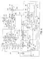
FIG. 1 is a hydraulic circuit diagram of a boom driving device according to a first embodiment of this invention; -
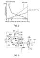
FIG. 2 is a diagram illustrating a switching timing of a regenerative control spool valve according to the first embodiment of this invention; -
FIG. 3 is a hydraulic circuit diagram of a boom driving device according to a second embodiment of this invention; -
FIG. 4 is a hydraulic circuit diagram of a boom driving device according to a third embodiment of this invention; and -
FIG. 5 is a hydraulic circuit diagram of a boom driving device according to a fourth embodiment of this invention. - Referring to
FIG. 1 of the drawings, a boom driving device of a construction machine according to this invention comprises a first main pump MP1 of a variable capacity type, a second main pump MP2 of a variable capacity type, and an auxiliary pump AP of a variable capacity type. A discharge port of the first main pump MP1 is connected to a first circuit through a first change-over valve V1. A discharge port of the second main pump MP2 is connected to a second circuit through a second change-over valve V2. A discharge port of the auxiliary pump AP is combined with the discharge port of the first main pump MP1 through the first change-over valve V1. All of the first and second main pumps MP1 and MP2 and the auxiliary pump AP comprise a pump capable of pressurizing and supplying a hydraulic fluid. - In the following description, with regard to valves operated in response to energy supplied from the outside, such as an electromagnetic valve operated in response to magnetic excitation of a solenoid and a pilot valve operated in response to a pilot pressure, a valve operation position with no external energy supply will be referred to as an OFF-position, and a valve operation position with external energy supply will be referred to as an ON-position. When there is a plurality of the ON-positions, they may be referred to as a first ON-position, a second ON-position, and so on.
- The first change-over valve V1 is a 4-port 2-position spool type change-over valve. In the first change-over valve V1, an end of the spool is provided with a pilot chamber, and another end of the spool is supported by a spring. The first change-over valve V1 is maintained in an OFF-position as illustrated in the figure by virtue of a biasing force of the spring while the pilot pressure is not supplied to the pilot chamber.
- The first change-over valve V1 in the OFF-position supplies a discharged fluid of the first main pump MP1 to the first circuit and causes a fluid discharged from the variable capacity type auxiliary pump AP to adjoin the discharge port of the first main pump MP1 through a check valve.
- As the first change-over valve V1 is switched to the ON-position located on the right side of the OFF-position in the figure by virtue of a pilot pressure in the pilot chamber, connection of a discharge port of the auxiliary pump AP to the discharge port of the first main pump MP1 is blocked while the fluid discharged from the first main pump MP1 is still supplied to the first circuit.
- The second change-over valve V2 is a 6-port 3-position spool type change-over valve. In the second change-over valve V2, pilot chambers are provided on both sides of the spool, and the spool is supported by a centering spring. The second change-over valve V2 is typically maintained in an OFF-position as illustrated in the figure by virtue of an elastic force of the centering spring.
- In the OFF-position, the second change-over valve V2 supplies a discharged fluid of the second main pump MP2 to the second circuit, and causes the discharged fluid of the auxiliary pump AP to adjoin the discharge port of the second main pump MP2.
- As the second change-over valve V2 is switched to a first ON-position located on the right side of the OFF-position in the figure by virtue of a pilot pressure of a pilot chamber on the right side, a flow of the discharged fluid from the auxiliary pump AP to the discharge port of the second main pump MP2 is disconnected while the discharged fluid of the second main pump MP2 is still supplied to the second circuit.
- As the second change-over valve V2 is switched to a second ON-position on the left side of the OFF-position in the figure by virtue of a pilot pressure of another pilot chamber on the left side, both a flow of the discharged fluid of the auxiliary pump AP to the discharge port of the second main pump MP2 and a flow of the discharged fluid of the second main pump MP2 to the second circuit are disconnected. In the second ON-position, the discharged fluid from the second main pump MP2 is supplied to a hydraulic motor M that drives the auxiliary pump AP. In addition, in the OFF-position and the first ON-position, a flow of the discharged fluid from the second main pump MP2 to the hydraulic motor M is disconnected.
- The pilot chamber of the first change-over valve V1 receives a pilot pressure from the pilot pressure source PP through an
electromagnetic valve 1. In the OFF-position illustrated in the figure, theelectromagnetic valve 1 is switched to an ON-position in which the pilot chamber is disconnected from the pilot pressure source PP by not exciting the solenoid. The discharged fluid of the pilot pressure source PP is supplied to the pilot chamber by exciting the solenoid. - One of the pilot chambers of the second change-over valve V2 is connected to the pilot pressure source PP through an
electromagnetic valve 2a. The other pilot chamber of the second change-over valve V2 is connected to the pilot pressure source PP through anelectromagnetic valve 2b. In the OFF-position illustrated in the figure, bothelectromagnetic valves - The solenoids of the
electromagnetic valves - The controller C is constituted by a microcomputer comprising a central processing unit (CPU), a read-only memory (ROM), a random access memory (RAM), and an input/output interface (I/O interface). The controller C may also constituted by a plurality of microcomputers.
- The controller C excites or does not excite the solenoids of the
electromagnetic valves - The first and second main pumps MP1 and MP2 are driven to rotate by an engine E comprising a rotational speed sensor not shown in the figure. The engine E is provided with a
generator 3 that generates electric power using a surplus torque. - The first circuit connected to the first main pump MP1 is provided with a change-over valve 4 for controlling a swivel motor, a change-over
valve 5 for controlling an arm cylinder, a boom 2-speed change-overvalve 6 for controlling a boom cylinder BC, a change-over valve 7 for controlling a preliminary attachment, and a change-overvalve 8 for controlling a left travel motor, according to an order from the upstream side. - The change-over valves 4 to 8 are connected to the first main pump MP1 through a
neutral passage 9, aparallel passage 10, and the first change-over valve V1. - A pilot
pressure control orifice 11 for generating a pilot pressure is provided in the downstream of the left travel motor change-overvalve 8 provided in theneutral passage 9. Theorifice 11 generates a high pilot pressure in the upstream side when the flow rate is high. Theorifice 11 generates a low pilot pressure in the upstream side when the flow rate is low. In other words, theorifice 11 generates the pilot pressure depending on a control position of the change-over valves 4 to 8 located in the upstream side. - A
pilot passage 12 is connected to theneutral passage 9 between theorifice 11 and the change-overvalve 8. Thepilot passage 12 is connected to aregulator 14 via an electromagnetic change-overvalve 13. Theregulator 14 controls a tilt angle of the first main pump MP1. - The electromagnetic change-over
valve 13 is a valve for supplying a pilot pressure to theregulator 14. The electromagnetic change-overvalve 13 selects one of thepilot passage 12 and the pilot pressure source PP as a source of the pilot pressure depending on a position thereof and connects the selected one to theregulator 14. In an OFF-position illustrated in the figure, the pressure of thepilot passage 12 is supplied to theregulator 14 as a pilot pressure. As an excitation current is supplied, the electromagnetic change-overvalve 13 is switched to an ON-position to supply the pressure of the pilot pressure source PP to theregulator 14 as a pilot pressure. - The solenoid of the electromagnetic change-over
valve 13 is connected to the controller C. As the operator of the construction machine inputs a signal, the controller C performs control such that the excitation current is supplied to the electromagnetic change-overvalve 13 to switch the electromagnetic change-overvalve 13 to the ON-position. Meanwhile, unless no signal is input from an operator, the controller C performs control such that the solenoid is not excited, and the electromagnetic change-overvalve 13 is maintained in the OFF-position. - The
regulator 14 controls the tilt angle of the first main pump MP1 in inversely proportional to the pilot pressure of thepilot passage 12 to set a discharge amount of the hydraulic fluid per rotation of the first main pump MP1. - When all of the change-over valves 4 to 8 are maintained in the OFF-position, that is, when the swivel motor, the arm cylinder, the boom cylinder BC, the preliminary attachment, and the left travel motor are not operated, the electromagnetic change-over
valve 13 reduces the discharge amount of the first main pump MP1, compared to other cases. Such a condition may be satisfied, for example, when a warm-up operation is performed. It is preferable to reduce an energy loss during the warm-up operation. - The second circuit connected to the second main pump MP2 is provided with, sequentially from the upstream side, a change-over
valve 15 for controlling a right travel motor, a change-overvalve 16 for controlling a bucket cylinder, aboom control valve 17 for controlling a boom cylinder BC, and an arm 2-speed change-overvalve 18 for controlling an arm cylinder. - The change-over
valves 15 to 18 are connected to the second main pump MP2 through aneutral passage 19 and the second change-over valve V2. The change-overvalve 16 and theboom control valve 17 are connected to the second main pump MP2 also through theparallel passage 20 and the second change-over valve V2. - A pilot
pressure control orifice 21 is provided in the downstream side of the change-overvalve 18 of theneutral passage 19. Theorifice 21 supplies a pressure of the upstream side to aregulator 23 of the second main pump MP2 through apilot passage 22 as a pilot pressure. Theregulator 23 controls the tilt angle of the second main pump MP2 in inverse proportion to the pilot pressure to set the discharge amount of the hydraulic fluid per rotation of the second main pump MP2. - The
boom control valve 17 is a 6-port 3-position spool type change-over valve. The input ports of theboom control valve 17 comprise a port connected to theneutral passage 19, a port connected to theparallel passage 20, and a port connected to a tank. In addition, the output ports of theboom control valve 17 comprise a pair of actuator ports and a port connected to the downstream side of theneutral passage 19. One of the actuator ports is connected to a piston-side chamber 25 of the boom cylinder BC through apassage 24. The other actuator port is connected to a rod-side chamber 30 of the boom cylinder BC through apassage 29. - The
boom control valve 17 is maintained in one of three positions including a neutral position, a descending position, and an ascending position. The position of theboom control valve 17 is selected based on a control from the operator of the construction machine. - In the neutral position, the
boom control valve 17 supplies the fluid discharged from the second main pump MP2 to the downstream side of theneutral passage 19 and disconnects the pair of the actuator ports. In this state, both the rod-side chamber 30 and the piston-side chamber 25 of the boom cylinder BC are tightly closed so that the boom is maintained in a current angle position. - In the descending position on the left side of the neutral position in the figure, the
boom control valve 17 supplies the fluid discharged to theneutral passage 19 from the second main pump MP2 to the rod-side chamber 30 and returns the hydraulic fluid of the piston-side chamber 25 to the tank through thebleed path 17a. As a result, the boom cylinder BC descends the boom. - In the ascending position on the right side of the neutral position in the figure, the
boom control valve 17 supplies the fluid discharged to theneutral passage 19 from the second main pump MP2 to the piston-side chamber 25 and returns the fluid discharged from the rod-side chamber 30 to the tank. As a result, the boom cylinder BC raises the boom. - The
passage 24 connecting one of the actuator ports of theboom control valve 17 and the piston-side chamber 25 is provided with a regenerativecontrol spool valve 26. The regenerativecontrol spool valve 26 has apilot chamber 26a facing an end of a spool and aspring 26b elastically supporting another end of the spool. - The regenerative
control spool valve 26 maintains an OFF-position illustrated in the figure by virtue of an elastic force of thespring 26b when the pilot pressure is not supplied to thepilot chamber 26a. When the pilot pressure is supplied to thepilot chamber 26a, the regenerativecontrol spool valve 26 is switched to an ON-position located on the right side of the OFF-position in the figure. - The regenerative
control spool valve 26 has ableed path 26c that connects the upstream side and the downstream side of thepassages 24 and apath 26d that connects the piston-side chamber 25 of the boom cylinder BC to the hydraulic motor M through aregenerative passage 27. - In the OFF-position illustrated in the figure, the regenerative
control spool valve 26 opens thebleed path 26c to connect the piston-side chamber 25 and one of the actuator ports of theboom control valve 17 and closes thepath 26d to disconnect the piston-side chamber 25 and theregenerative passage 27. - In the ON-position on the right side of the OFF-position in the figure, the regenerative
control spool valve 26 closes thebleed path 26c and opens thepath 26d. As a result, the piston-side chamber 25 and one of the actuator ports of theboom control valve 17 are disconnected, and the piston-side chamber 25 and theregenerative passage 27 are connected. - The regenerative
control spool valve 26 not only selects one of the pair of the positions alternatively but also maintains both thepassage 24 and theregenerative passage 27 in a partial communication state and controls the opening areas thereof depending on the pilot pressure of thepilot chamber 26a. - The
regenerative passage 27 is provided with acheck valve 28 that allows a flow of the hydraulic fluid directed to the hydraulic motor M from thepath 26d and blocks a reversal flow. - The
passage 24 communicating with the piston-side chamber 25 of the boom cylinder BC and thepassage 29 communicating with the rod-side chamber 30 of the boom cylinder BC are connected to each other through arecirculating passage 31 provided with a recirculatingflow control valve 32. The recirculatingflow control valve 32 is a spool valve including apilot chamber 32a facing an end of a spool and aspring 32b elastically supporting another end of the spool. - The recirculating
flow control valve 32 has arecirculating path 32c communicating with therecirculating passage 31. The recirculatingflow control valve 32 serves as a variable orifice that closes therecirculating path 32c in an OFF-position and opens therecirculating path 32c depending on a pilot pressure in an ON-position, thereby controlling a flow rate of therecirculating passage 31. - The
recirculating passage 31 is provided with acheck valve 33 that allows a flow of the hydraulic fluid from the piston-side chamber 25 to thepassage 29 and blocks a reversal flow. - The pilot pressure source PP is connected to the
pilot chamber 26a of the regenerativecontrol spool valve 26 and thepilot chamber 32a of the recirculatingflow control valve 32 through a proportionalelectromagnetic valve 34. The proportionalelectromagnetic valve 34 comprises asolenoid 34a and aspring 34b that elastically supports a valve main body. Thesolenoid 34a is excited by an excitation current supplied from the controller C and drives the valve main body against thespring 34b. - The proportional
electromagnetic valve 34 maintains an OFF-position illustrated in the figure by virtue of an elastic force of thespring 34b when thesolenoid 34a is not excited. As the excitation current is supplied from the controller C to thesolenoid 34a, the proportionalelectromagnetic valve 34 is switched to an ON-position to connect thepilot chambers pilot chambers electromagnetic valve 34. - However, the elastic force of the
spring 32b of the recirculatingflow control valve 32 is set to be higher than the elastic force of thespring 26b of the regenerativecontrol spool valve 26. Under the same pilot pressure, a timing that the recirculatingflow control valve 32 opens therecirculating path 32c is set to be delayed from a timing that the regenerativecontrol spool valve 26 is set to the ON-position. - The hydraulic motor M connected to the regenerative
control spool valve 26 is combined with a motor/generator 35 serving as an electric motor and a generator and rotating together with the auxiliary pump AP in synchronization about an identical axis. The motor/generator 35 is driven to rotate by the hydraulic motor M to serve as a generator. The electric power generated by the motor/generator 35 is charged in abattery 37 via aninverter 36. Thebattery 37 is connected to the controller C, and the controller C receives a signal indicating an electric charge amount of thebattery 37. - The
battery 37 is provided with abattery charger 38. Thebattery charger 38 charges thebattery 37 using the electric power generated by thegenerator 3. Apower source 39 of other systems, such as a general home use power source, may also be used to charge thebattery charger 38. - The hydraulic motor M is a variable capacity type and comprises a
regulator 40 for controlling a tilt angle. Theregulator 40 changes the tilt angle of the hydraulic motor M in response to the signal from the controller C. - The auxiliary pump AP is also a variable capacity type and has a
regulator 41 for controlling a tilt angle. Theregulator 41 changes the tilt angle of the auxiliary pump AP in response to the signal from the controller C. - According to the configuration described above, when the hydraulic motor M drives the motor/
generator 35 to rotate, it is possible to prevent a driving load of the auxiliary pump AP from being applied to the hydraulic motor M by minimizing the tilt angle of the auxiliary pump AP. When the motor/generator 35 serves as an electric motor, the auxiliary pump AP may operate as a pump by driving the auxiliary pump AP to rotate using a part of the output torque of the motor/generator 35. - In the boom driving device configured as described above, when the engine E is driven in a state where the
electromagnetic valves - If the auxiliary pump AP operates simultaneously to discharge hydraulic fluid, the discharged fluid joins the discharged fluids of the first and second main pumps MP1 and MP2 and is supplied to the first and second circuits.
- In order to operate the auxiliary pump AP, it is necessary to drive the motor/
generator 35 as an electric motor using the electric power of thebattery 37 and rotate the auxiliary pump AP using a rotational torque thereof. In this case, the hydraulic motor M preferably reduces a rotational resistance by minimizing the tilt angle to minimize a loss in the output power of the motor/generator 35 serving as an electrical motor. The auxiliary pump AP may also be operated using the rotational power of the hydraulic motor M. - The boom driving device further comprises a
pressure sensor 42 that detects a pressure supplied to theregulator 14 of the first main pump MP1 and apressure sensor 43 that detects a pressure supplied to theregulator 23 of the second main pump MP2. The detection data of thepressure sensors - The controller C controls the tilt angle of the auxiliary pump AP in response to the pressure signals input from the
pressure sensors pressure sensors - Meanwhile, as the first change-over valve V1 is switched to the ON-position on the right side of the OFF-position in the figure, only the fluid discharged from the first main pump MP1 is supplied to the first circuit. As the second change-over valve V2 is switched to the first ON-position on the right side of the OFF-position in the figure, only the fluid discharged from the second main pump MP2 is supplied to the second circuit.
- As the second change-over valve V2 is switched to the second ON-position on the left side of the OFF-position in the figure, the fluid discharged from the second main pump MP2 is supplied to the hydraulic motor M. Therefore, if the controller C switches the second change-over valve V2 to the second ON-position using the
electromagnetic valve 2b when the actuator connected to the second circuit is not actuated, the hydraulic motor M is driven to rotate such that the motor/generator 35 serves as a generator. The electric power generated by the motor/generator 35 is charged in thebattery 37 via theinverter 36. - When the hydraulic motor M drives the motor/
generator 35 to rotate, it is preferable that the tilt angle of the auxiliary pump AP be maintained at minimum in order to improve the electric power generation efficiency. - The controller C has a function of detecting an electric charge amount of the
battery 37 and controlling a rotation speed of the hydraulic motor M depending on the electric charge amount. - Meanwhile, the hydraulic motor M may be driven to rotate using the returning fluid discharged from the piston-
side chamber 25 when the boom cylinder BC operates to descend the boom. - When the boom cylinder BC contracts, the
boom control valve 17 in the descending position controls the opening area of thebleed path 17a in response to a control amount directed by the operator. In other words, the opening area of thebleed path 17a of theboom control valve 17 is controlled such that the returning fluid returns from the piston-side chamber 25 of the contracting boom cylinder BC to the tank at a rate corresponding to a descending speed of the boom intended by the operator. - When the boom cylinder BC contracts, the controller C excites the
solenoid 34a to switch the proportionalelectromagnetic valve 34 to the ON-position. As the proportionalelectromagnetic valve 34 opens, the pilot pressure from the pilot pressure source PP is introduced into thepilot chamber 26a of the regenerativecontrol spool valve 26 and thepilot chamber 32a of the recirculatingflow control valve 32. - However, as descried above, the elastic force of the
spring 26b of the regenerativecontrol spool valve 26 is smaller than the elastic force of thespring 32b of the recirculatingflow control valve 32. Accordingly, the regenerativecontrol spool valve 26 is first switched to the ON-position in response to the pilot pressure from the pilot pressure source PP. In this case, the switching level of the regenerativecontrol spool valve 26 is proportional to the pilot pressure. - As the pilot pressure is introduced into the
pilot chamber 26a of the regenerativecontrol spool valve 26, the opening area of thebleed path 26c of the regenerativecontrol spool valve 26 decreases, and the opening area of thepath 26d increases. That is, while thepassage 24 is narrowed, the flow rate of the returning fluid of theregenerative passage 27 to the hydraulic motor M increases. - The timing that the controller C switches the proportional
electromagnetic valve 34 to open thepath 26d of the regenerativecontrol spool valve 26 is controlled based on a stroke of the spool of theboom control valve 17 as described below. - The controller C starts switching from the OFF-position to the ON-position of the regenerative
control spool valve 26 after the stroke of theboom control valve 17 reaches a predetermined amount, and thebleed path 17a reaches a predetermined opening area. - In order to implement this control, the
boom control valve 17 comprises astroke sensor 50 that electrically detects a stroke position of the spool, so that the detected stroke position is input into the controller C as a signal. - The
stroke sensor 50 may be a sensor capable of directly detecting a specific stroke position of the spool such as a limit switch or a sensor capable of indirectly detecting a stroke position on the basis of a duration of operation, a control position of a control lever, or the like. - Referring to
FIG. 2 , the controller C performs control such that the opening area of thebleed path 26c of the regenerativecontrol spool valve 26 decreases to a predetermined level, and thepath 26d starts to be opened, when theboom control valve 17 is switched and manipulated by the operator from the point N corresponding to the neutral position, and the opening area of thebleed path 17a reaches a predetermined level corresponding to the point b as the stroke reaches the point b. In other words, the controller C controls the proportionalelectromagnetic valve 34 such that thepath 26d of the regenerativecontrol spool valve 26 starts to open as the stroke of theboom control valve 17 reaches the point b. - As a result, as the pilot pressure is introduced into the
pilot chamber 26a, and the regenerativecontrol spool valve 26 displaces toward the ON-position, the returning fluid from the piston-side chamber 25 of the boom cylinder BC is divided into a hydraulic fluid returning to thepassage 24 via thebleed path 26c and a hydraulic fluid supplied to the hydraulic motor M via thepath 26d depending on the displacement position of the regenerativecontrol spool valve 26. - In
FIG. 2 , a section between the point N and the point b is a dead zone of the spool control of the regenerativecontrol spool valve 26. The section after the point b is a controllable zone. Therefore, an inclination of the opening area against the stroke changes at the point b. - When the stroke of the spool is insignificant, and the opening area of the
bleed path 17a of theboom control valve 17 is smaller than the opening area of thebleed path 26c, the opening area of thebleed path 17a dominantly affects the returning flow rate of thepassage 24. When the stroke of the spool increases and the opening area of thebleed path 26c of the regenerativecontrol spool valve 26 becomes smaller than the opening area of thebleed path 17a, the opening area of thebleed path 26c dominantly affects the returning flow rate of thepassage 24. - The controller C controls the loads of the hydraulic motor M and the auxiliary pump AP by controlling the tilt angle of the hydraulic motor M and the auxiliary pump AP in order to maintain a desired descending speed of the boom.
- When the regenerative
control spool valve 26 operates, and the returning fluid is introduced into theregenerative passage 27 in order to start to rotate the hydraulic motor M in an inoperative state, a slight shock may be generated. - The controller C performs control such that the returning fluid is introduced into the
regenerative passage 27 after a total amount of the returning fluid from the boom cylinder BC increases to a certain level. This determination can be performed by determining as to whether or not the opening area of thebleed path 17a has reached a predetermined area from the stroke position of theboom control valve 17. Therefore, it is possible to suppress an influence on a boom descending speed that a shock generated by starting the hydraulic motor M may exert. As a result, it is possible to alleviate a discomfort that the operator may feel when starting the hydraulic motor M. - When the boom descending speed intended by the operator is high, the stroke amount of the
boom control valve 17 increases, and the opening area of the proportionalelectromagnetic valve 34 increases accordingly. As a result, the pilot pressure applied to thepilot chambers flow control valve 32 is switched to the ON-position, so that therecirculating path 32c is opened. - As the
recirculating path 32c is opened, a part of the returning fluid from the piston-side chamber 25 of the boom cylinder BC is supplied to the rod-side chamber 30 of the boom cylinder BC through therecirculating passage 31 and thepassage 29. - When the descending speed of the boom cylinder BC is high, the returning fluid of the piston-
side chamber 25 is supplied to the rod-side chamber 30 in order to prevent a negative pressure in the rod-side chamber 30 that may generate an abnormal noise. - The opening area of the
recirculating path 32c and the timing that the recirculatingflow control valve 32 is switched to the ON-position depend on the opening area of the proportionalelectromagnetic valve 34, the elastic force of thespring 32b, and the like. They are set in advance based on properties required to the boom cylinder BC. - It is possible to omit the
recirculating passage 31 and the recirculatingflow control valve 32 such that the returning fluid from the piston-side chamber 25 is distributed only to thepassage 24 and theregenerative passage 27. - When the regenerative
control spool valve 26 is in a full stroke state toward the ON-position, thebleed path 26c is blocked, and thepassage 24 connected to theboom control valve 17 is disconnected from the piston-side chamber 25. However, the regenerativecontrol spool valve 26 may be configured such that thepassage 24 communicates with the piston-side chamber 25 with a minimum opening area when the regenerativecontrol spool valve 26 is in the full stroke state toward the ON-position. Similarly, in this case, as the opening area of thepassage 24 decreases, the opening area of thepath 26d increases. Therefore, the flow rate of the returning fluid introduced into theregenerative passage 27 increases similarly. - However, if the
passage 24 is perfectly blocked, the whole amount of the returning fluid is introduced into theregenerative passage 27. By perfectly blocking thepassage 24, therefore, it is possible to fully use the energy generated by descending the boom to drive the hydraulic motor M without generating a loss. - The minimum opening area described above refers to the smallest opening area that the
path 26d experiences in the course of the spool stroke of the regenerativecontrol spool valve 26 between the OFF-position and the full stroke state. - Referring to
FIG. 3 , a second embodiment of this invention will be described. - This embodiment is different from the first embodiment in that a proportional electromagnetic
pressure reducing valve 44 is provided instead of the proportionalelectromagnetic valve 34. The other components are identical to those of the first embodiment. With respect to the components that have the same construction as those of the first embodiment are given identical component numbers, and their description is herein omitted. - The proportional electromagnetic
pressure reducing valve 44 comprises asolenoid 44a and aspring 44b. Thespring 44b exerts an elastic force to bias the valve main body toward an OFF-position. Thesolenoid 44a drives the valve main body toward an ON-position against thespring 44b in response to the excitation current from the controller C. - Similar to the proportional
electromagnetic valve 34, in the ON-position, the proportional electromagneticpressure reducing valve 44 supplies the pilot pressure from the pilot pressure source PP to thepilot chamber 26a of the regenerativecontrol spool valve 26 and thepilot chamber 32a of the recirculatingflow control valve 32. Meanwhile, in the OFF-position, the pilot pressures of thepilot chambers - Similarly, in the boom driving device, the controller C detects that the
bleed path 17a connecting thepassage 24 and the tank has a predetermined opening area from the stroke position of theboom control valve 17. Then, the controller C switches the regenerativecontrol spool valve 26 to guide the returning fluid from the piston-side chamber 25 to theregenerative passage 27 through thebleed path 26c. - Therefore, it is possible to suppress an influence on a boom descending speed that a shock generated by starting the hydraulic motor M may exert. As a result, it is possible to alleviate a discomfort that the operator may feel when starting the hydraulic motor M using the returning fluid of the
regenerative passage 27. - Unlike the proportional
electromagnetic valve 34 that controls connection or disconnection with the pilot pressure source PP, the proportional electromagneticpressure reducing valve 44 can perform a wide range of control for the pilot pressure supplied to thepilot chambers control spool valve 26 across a wide range. - Referring to
FIG. 4 , a third embodiment of the invention will be described. - According to this embodiment, the pilot pressure guided to the
pilot chamber 32a of the recirculatingflow control valve 32 is supplied, not from the pilot pressure source PP through the proportional electromagneticpressure reducing valve 44, but from a change-over valve provided in theboom control valve 17. - Specifically, the change-over valve is switched as the
boom control valve 17 is switched to the descending position, so that the pilot pressure of the pilot pressure source PP is supplied to thepilot chamber 32a of the recirculatingflow control valve 32. - Since the other components are identical to those of the second embodiment, they are given identical component numbers, and their description is herein omitted.
- In this boom driving device also, the controller C controls the timing that the returning fluid is guided to the
regenerative passage 27 by controlling the regenerativecontrol spool valve 26. - Specifically, the controller C detects that the opening area of the
bleed path 17a serving as a passage for connecting the tank and thepassage 24 connected to the piston-side chamber 25 has reached a predetermined area from the stroke position of theboom control valve 17. The controller C then controls the regenerativecontrol spool valve 26 such that the returning fluid is introduced into theregenerative passage 27. - As a result, it is possible to suppress an influence on a boom descending speed that a shock generated by starting the hydraulic motor M may exert and alleviate a discomfort of the operator when the hydraulic motor M is actuated by the returning fluid of the boom cylinder BC.
- According to this embodiment, the switching timing of the recirculating
flow control valve 32 is determined on the basis of a control amount of theboom control valve 17. The controller C is not involved in the switching timing determination of the recirculatingflow control valve 32. As a result, the switching of the recirculatingflow control valve 32 is not synchronized with the switching of the regenerativecontrol spool valve 26. - If the switching of the regenerative
control spool valve 26 is synchronized with the switching of the recirculatingflow control valve 32, it may be difficult to control a total flow rate of the returning fluid from the boom cylinder BC, that is, the descending speed of the boom cylinder BC. - According to this embodiment, since the control of the recirculating
flow control valve 32 is not synchronized with the control of the regenerativecontrol spool valve 26, it is possible to easily control a total flow rate of the returning fluid. - Referring to
FIG. 5 , a fourth embodiment of this invention will now be described. - According to this embodiment, a proportional electromagnetic
pressure reducing valve 46, which is different from the proportional electromagneticpressure reducing valve 44, is provided between the pilot pressure source PP and thepilot chamber 32a of the recirculatingflow control valve 32. Since the other components are identical to those of the second embodiment, they are given identical component numbers, and their description is herein omitted. - The proportional electromagnetic
pressure reducing valve 46 comprises aspring 46b and asolenoid 46a connected to the controller C. While thesolenoid 46a is not excited, the proportional electromagneticpressure reducing valve 46 is maintained in an OFF-position by virtue of thespring 46b. In the OFF-position, the proportional electromagneticpressure reducing valve 46 releases thepilot chamber 32a to the tank. As thesolenoid 46a is excited, the proportional electromagneticpressure reducing valve 46 is switched to an ON-position against thespring 46b. In the ON-position, the proportional electromagneticpressure reducing valve 46 connects thepilot chamber 32a to the pilot pressure source PP. - According to this embodiment also, the controller C first detects from the stroke position of the
boom control valve 17 that the opening area of thebleed path 17a serving as a passage connecting the piston-side chamber 25 and the tank via thepassages 24 has reached a predetermined area. The controller C then controls the regenerativecontrol spool valve 26 such that the returning fluid is introduced into theregenerative passage 27. - As a result, it is possible to suppress an influence on a boom descending speed that a shock generated by starting the hydraulic motor M may exert and alleviate a discomfort of the operator when the hydraulic motor M is actuated by the returning fluid of the boom cylinder BC.
- According to this embodiment also, it is possible to individually control the pilot pressure of the recirculating
flow control valve 32 and the pilot pressure of the regenerativecontrol spool valve 26. For this reason, it is possible to control the regenerativecontrol spool valve 26 without being influenced by the flow rate introduced into theregenerative passage 31. Therefore, it is possible to easily control the descending speed of the boom cylinder BC. In addition, it is possible to improve freedom in control of the recirculatingflow control valve 32 and the regenerativecontrol spool valve 26. - The contents of
Tokugan 2012-70053, with a filing date of March 26, 2012 - Although the invention has been described above with reference to certain embodiments, the invention is not limited to the embodiments described above. Modifications and variations of the embodiments described above will occur to those skilled in the art, within the scope of the claims.
- This invention preferably applies to a boom driving device of a construction machine.
- The embodiments of this invention in which an exclusive property or privilege is claimed are defined as follows:
Claims (4)
- A boom driving device, comprising:a boom cylinder that elongates to rotate a boom upward in response to a supply of working fluid to a working chamber and contracts to rotate the boom downward in response to discharge of the working fluid from the working chamber;a boom change-over valve that displaces between a pump position connecting the working chamber to a pump and a tank position connecting the working chamber to a tank while increasing a connecting cross-sectional area between the working chamber and the tank when displacing towards the tank position;a power generator;a regenerative passage that is branched off at a position upstream of the boom change-over valve from a passage connecting the working chamber to the tank and supplies a part of the working fluid discharged from the working chamber to drive the generator to rotate;a regenerative control valve that opens and closes the regenerative passage;a sensor that detects a displacement position of the boom change-over valve;a programmable controller programmed to:open the regenerative control valve when a displacement position of the boom change-over valve has exceeded a predetermined position in a course of displacement towards the tank position.
- The boom driving device according to Claim 1, further comprising a working passage connecting the working chamber and the boom change-over valve, wherein the regenerative control valve is configured to displace between an ON-position that opens the regenerative passage and closes the working passage and an OFF-position that closes the regenerative passage and opens the working passage while increasing a connecting cross-sectional area to the regenerative passage as a displacement position approaches the ON-position from the OFF-position, and the controller is further programmed to cause the regenerative control valve to start displacement from the OFF-position towards the ON-position after the displacement position of the boom change-over valve has exceeded the predetermined position in the course of displacement towards the tank position.
- The boom driving device according to Claim 2, wherein the regenerative control valve comprises a spool that displaces between the OFF-position and the ON-position, a pilot chamber exerting a pilot pressure on an end of the spool, and a spring that biases the spool in a direction opposite to the pilot pressure, the boom driving device further comprises an electro-magnetic valve that supplies the pilot pressure to the pilot chamber, and the controller is further programmed to control the regenerating control valve via the electro-magnetic valve.
- The driving device according to Claim 3, wherein the electro-magnetic valve comprises a proportional electro-magnetic valve.
Applications Claiming Priority (2)
| Application Number | Priority Date | Filing Date | Title |
|---|---|---|---|
| JP2012070053A JP5901381B2 (en) | 2012-03-26 | 2012-03-26 | Construction machine control equipment |
| PCT/JP2013/057632 WO2013146409A1 (en) | 2012-03-26 | 2013-03-18 | Boom drive device |
Publications (3)
| Publication Number | Publication Date |
|---|---|
| EP2833003A1 true EP2833003A1 (en) | 2015-02-04 |
| EP2833003A4 EP2833003A4 (en) | 2015-12-30 |
| EP2833003B1 EP2833003B1 (en) | 2017-02-15 |
Family
ID=49259670
Family Applications (1)
| Application Number | Title | Priority Date | Filing Date |
|---|---|---|---|
| EP13767782.9A Not-in-force EP2833003B1 (en) | 2012-03-26 | 2013-03-18 | Boom drive device |
Country Status (6)
| Country | Link |
|---|---|
| US (1) | US9476437B2 (en) |
| EP (1) | EP2833003B1 (en) |
| JP (1) | JP5901381B2 (en) |
| KR (1) | KR101624064B1 (en) |
| CN (1) | CN103998796B (en) |
| WO (1) | WO2013146409A1 (en) |
Families Citing this family (16)
| Publication number | Priority date | Publication date | Assignee | Title |
|---|---|---|---|---|
| JP6155159B2 (en) * | 2013-10-11 | 2017-06-28 | Kyb株式会社 | Hybrid construction machine control system |
| JP6220228B2 (en) * | 2013-10-31 | 2017-10-25 | 川崎重工業株式会社 | Hydraulic drive system for construction machinery |
| KR101778902B1 (en) | 2014-01-28 | 2017-09-14 | 히다찌 겐끼 가부시키가이샤 | Work machine hydraulic energy recovery device |
| CN106661867B (en) * | 2014-06-20 | 2020-12-11 | 住友重机械工业株式会社 | Excavator and its control method |
| JP6291394B2 (en) * | 2014-10-02 | 2018-03-14 | 日立建機株式会社 | Hydraulic drive system for work machines |
| CN106460880B (en) * | 2014-12-16 | 2018-04-24 | Kyb株式会社 | Fluid pressure control device for construction machine |
| KR101899745B1 (en) * | 2015-03-11 | 2018-09-17 | 케이와이비 가부시키가이샤 | Fluid pressure control device |
| DE102015208215B4 (en) * | 2015-05-04 | 2024-05-02 | Stabilus Gmbh | Electromechanical control arrangement for a chair |
| KR101947301B1 (en) * | 2015-09-29 | 2019-02-12 | 히다찌 겐끼 가부시키가이샤 | Pressure oil energy recovery device of working machine |
| US10174770B2 (en) | 2015-11-09 | 2019-01-08 | Caterpillar Inc. | System and method of hydraulic energy recovery for machine start-stop and machine ride control |
| KR101597743B1 (en) * | 2015-11-12 | 2016-02-25 | (주)경성하이테크 | Oil pressure equipment control system |
| KR102510852B1 (en) * | 2015-12-04 | 2023-03-16 | 현대두산인프라코어 주식회사 | Hydraulic system and hydraulic control method for construction machine |
| CN106703110B (en) * | 2017-03-02 | 2019-07-30 | 柳州柳工挖掘机有限公司 | Excavator intelligent damping hydraulic control method and control system |
| KR20180114765A (en) | 2017-04-11 | 2018-10-19 | 두산중공업 주식회사 | Retainer for gas turbine blade, turbine unit and gas turbine using the same |
| JP7648365B2 (en) * | 2020-05-29 | 2025-03-18 | ナブテスコ株式会社 | Fluid system, construction machine, and control method |
| JP7530312B2 (en) * | 2021-02-12 | 2024-08-07 | 川崎重工業株式会社 | Multi-Control Valve |
Family Cites Families (16)
| Publication number | Priority date | Publication date | Assignee | Title |
|---|---|---|---|---|
| DE10009918A1 (en) * | 2000-03-01 | 2001-09-06 | Bayerische Motoren Werke Ag | Hydraulic stabilizing system esp. for motor vehicle chassis has single fail-safe-valve only switched in front of directional valve |
| US6502500B2 (en) * | 2001-04-30 | 2003-01-07 | Caterpillar Inc | Hydraulic system for a work machine |
| JP4410512B2 (en) * | 2003-08-08 | 2010-02-03 | 日立建機株式会社 | Hydraulic drive |
| GB2420634A (en) * | 2004-11-24 | 2006-05-31 | Perry Slingsby Systems Ltd | Control system for articulated manipulator arm |
| JP2006336306A (en) * | 2005-06-02 | 2006-12-14 | Shin Caterpillar Mitsubishi Ltd | Work machine |
| WO2006129422A1 (en) | 2005-06-02 | 2006-12-07 | Shin Caterpillar Mitsubishi Ltd. | Working machine |
| JP2006348978A (en) * | 2005-06-13 | 2006-12-28 | Sumitomo (Shi) Construction Machinery Manufacturing Co Ltd | Driving device of work machine |
| US7634911B2 (en) * | 2007-06-29 | 2009-12-22 | Caterpillar Inc. | Energy recovery system |
| WO2009005425A1 (en) | 2007-07-02 | 2009-01-08 | Parker Hannifin Ab | Fluid valve arrangement |
| JP5412077B2 (en) * | 2008-10-01 | 2014-02-12 | キャタピラー エス エー アール エル | Power regeneration mechanism for hydraulic work machines |
| JP2011127727A (en) * | 2009-12-21 | 2011-06-30 | Sumitomo (Shi) Construction Machinery Co Ltd | Hydraulic circuit of construction machine |
| JP5461234B2 (en) * | 2010-02-26 | 2014-04-02 | カヤバ工業株式会社 | Construction machine control equipment |
| JP2012012821A (en) * | 2010-06-30 | 2012-01-19 | Tadao Osuga | Hydraulic circuit of hydraulic shovel |
| CN102094434B (en) * | 2011-01-11 | 2012-05-30 | 浙江大学 | System for differential recovery of potential energy of boom of oil liquid hybrid power excavating machine |
| CN202073132U (en) * | 2011-04-29 | 2011-12-14 | 中外合资沃得重工(中国)有限公司 | Descending acceleration device of excavator movable arm |
| CN102182730A (en) * | 2011-05-05 | 2011-09-14 | 四川省成都普什机电技术研究有限公司 | Movable arm flow re-generation system with potential energy recovery device for excavator |
-
2012
- 2012-03-26 JP JP2012070053A patent/JP5901381B2/en active Active
-
2013
- 2013-03-18 EP EP13767782.9A patent/EP2833003B1/en not_active Not-in-force
- 2013-03-18 US US14/373,650 patent/US9476437B2/en not_active Expired - Fee Related
- 2013-03-18 CN CN201380004343.9A patent/CN103998796B/en not_active Expired - Fee Related
- 2013-03-18 KR KR1020147017368A patent/KR101624064B1/en not_active Expired - Fee Related
- 2013-03-18 WO PCT/JP2013/057632 patent/WO2013146409A1/en not_active Ceased
Also Published As
| Publication number | Publication date |
|---|---|
| WO2013146409A1 (en) | 2013-10-03 |
| EP2833003B1 (en) | 2017-02-15 |
| KR20140103989A (en) | 2014-08-27 |
| US20150007557A1 (en) | 2015-01-08 |
| EP2833003A4 (en) | 2015-12-30 |
| CN103998796B (en) | 2016-03-09 |
| JP5901381B2 (en) | 2016-04-06 |
| JP2013200023A (en) | 2013-10-03 |
| US9476437B2 (en) | 2016-10-25 |
| KR101624064B1 (en) | 2016-05-24 |
| CN103998796A (en) | 2014-08-20 |
Similar Documents
| Publication | Publication Date | Title |
|---|---|---|
| EP2833003B1 (en) | Boom drive device | |
| US9228323B2 (en) | Control system for construction machine | |
| KR101218018B1 (en) | Control device for hybrid construction machine | |
| KR101568441B1 (en) | Controller of hybrid construction machine | |
| KR101568440B1 (en) | Controller of hybrid construction machine | |
| JP5378061B2 (en) | Control device for hybrid construction machine | |
| KR101595584B1 (en) | Controller of hybrid construction machine | |
| US10179987B2 (en) | Control system for hybrid construction machine | |
| US9995018B2 (en) | Control system of hybrid construction machine | |
| CN104011399B (en) | Hydraulic control circuits and hydraulic control circuits for construction machinery | |
| KR20120123095A (en) | Hybrid construction equipment control system | |
| US20160312443A1 (en) | Control system of hybrid construction machine | |
| WO2011004880A1 (en) | Hybrid construction machine | |
| CN104379945A (en) | Control system for construction machine | |
| CN107532627B (en) | Control system for construction machine | |
| JP2014227949A (en) | Engine starting device | |
| JP5208067B2 (en) | Control device for hybrid construction machine | |
| JP5197479B2 (en) | Hybrid construction machinery | |
| JP2017125537A (en) | Hybrid work machine control system | |
| US9651062B2 (en) | Construction machine and controller | |
| JP5872170B2 (en) | Construction machine control equipment | |
| KR101740733B1 (en) | Steering Device for Construction Machinery |
Legal Events
| Date | Code | Title | Description |
|---|---|---|---|
| PUAI | Public reference made under article 153(3) epc to a published international application that has entered the european phase |
Free format text: ORIGINAL CODE: 0009012 |
|
| 17P | Request for examination filed |
Effective date: 20141022 |
|
| AK | Designated contracting states |
Kind code of ref document: A1 Designated state(s): AL AT BE BG CH CY CZ DE DK EE ES FI FR GB GR HR HU IE IS IT LI LT LU LV MC MK MT NL NO PL PT RO RS SE SI SK SM TR |
|
| AX | Request for extension of the european patent |
Extension state: BA ME |
|
| DAX | Request for extension of the european patent (deleted) | ||
| RA4 | Supplementary search report drawn up and despatched (corrected) |
Effective date: 20151202 |
|
| RIC1 | Information provided on ipc code assigned before grant |
Ipc: F04B 7/02 20060101ALI20151126BHEP Ipc: E02F 9/22 20060101ALI20151126BHEP Ipc: E02F 9/20 20060101ALI20151126BHEP Ipc: F15B 21/14 20060101AFI20151126BHEP |
|
| RAP1 | Party data changed (applicant data changed or rights of an application transferred) |
Owner name: KYB CORPORATION |
|
| GRAP | Despatch of communication of intention to grant a patent |
Free format text: ORIGINAL CODE: EPIDOSNIGR1 |
|
| INTG | Intention to grant announced |
Effective date: 20161104 |
|
| RIN1 | Information on inventor provided before grant (corrected) |
Inventor name: YONEHARA, YASUHIRO Inventor name: EGAWA, MASAHIRO Inventor name: KAWASAKI, HARUHIKO |
|
| GRAS | Grant fee paid |
Free format text: ORIGINAL CODE: EPIDOSNIGR3 |
|
| GRAA | (expected) grant |
Free format text: ORIGINAL CODE: 0009210 |
|
| AK | Designated contracting states |
Kind code of ref document: B1 Designated state(s): AL AT BE BG CH CY CZ DE DK EE ES FI FR GB GR HR HU IE IS IT LI LT LU LV MC MK MT NL NO PL PT RO RS SE SI SK SM TR |
|
| REG | Reference to a national code |
Ref country code: CH Ref legal event code: EP Ref country code: GB Ref legal event code: FG4D |
|
| REG | Reference to a national code |
Ref country code: IE Ref legal event code: FG4D |
|
| REG | Reference to a national code |
Ref country code: AT Ref legal event code: REF Ref document number: 868084 Country of ref document: AT Kind code of ref document: T Effective date: 20170315 |
|
| REG | Reference to a national code |
Ref country code: DE Ref legal event code: R096 Ref document number: 602013017506 Country of ref document: DE |
|
| REG | Reference to a national code |
Ref country code: NL Ref legal event code: MP Effective date: 20170215 |
|
| REG | Reference to a national code |
Ref country code: LT Ref legal event code: MG4D |
|
| REG | Reference to a national code |
Ref country code: AT Ref legal event code: MK05 Ref document number: 868084 Country of ref document: AT Kind code of ref document: T Effective date: 20170215 |
|
| PG25 | Lapsed in a contracting state [announced via postgrant information from national office to epo] |
Ref country code: HR Free format text: LAPSE BECAUSE OF FAILURE TO SUBMIT A TRANSLATION OF THE DESCRIPTION OR TO PAY THE FEE WITHIN THE PRESCRIBED TIME-LIMIT Effective date: 20170215 Ref country code: LT Free format text: LAPSE BECAUSE OF FAILURE TO SUBMIT A TRANSLATION OF THE DESCRIPTION OR TO PAY THE FEE WITHIN THE PRESCRIBED TIME-LIMIT Effective date: 20170215 Ref country code: GR Free format text: LAPSE BECAUSE OF FAILURE TO SUBMIT A TRANSLATION OF THE DESCRIPTION OR TO PAY THE FEE WITHIN THE PRESCRIBED TIME-LIMIT Effective date: 20170516 Ref country code: NO Free format text: LAPSE BECAUSE OF FAILURE TO SUBMIT A TRANSLATION OF THE DESCRIPTION OR TO PAY THE FEE WITHIN THE PRESCRIBED TIME-LIMIT Effective date: 20170515 Ref country code: FI Free format text: LAPSE BECAUSE OF FAILURE TO SUBMIT A TRANSLATION OF THE DESCRIPTION OR TO PAY THE FEE WITHIN THE PRESCRIBED TIME-LIMIT Effective date: 20170215 |
|
| PG25 | Lapsed in a contracting state [announced via postgrant information from national office to epo] |
Ref country code: RS Free format text: LAPSE BECAUSE OF FAILURE TO SUBMIT A TRANSLATION OF THE DESCRIPTION OR TO PAY THE FEE WITHIN THE PRESCRIBED TIME-LIMIT Effective date: 20170215 Ref country code: PT Free format text: LAPSE BECAUSE OF FAILURE TO SUBMIT A TRANSLATION OF THE DESCRIPTION OR TO PAY THE FEE WITHIN THE PRESCRIBED TIME-LIMIT Effective date: 20170615 Ref country code: BG Free format text: LAPSE BECAUSE OF FAILURE TO SUBMIT A TRANSLATION OF THE DESCRIPTION OR TO PAY THE FEE WITHIN THE PRESCRIBED TIME-LIMIT Effective date: 20170515 Ref country code: LV Free format text: LAPSE BECAUSE OF FAILURE TO SUBMIT A TRANSLATION OF THE DESCRIPTION OR TO PAY THE FEE WITHIN THE PRESCRIBED TIME-LIMIT Effective date: 20170215 Ref country code: NL Free format text: LAPSE BECAUSE OF FAILURE TO SUBMIT A TRANSLATION OF THE DESCRIPTION OR TO PAY THE FEE WITHIN THE PRESCRIBED TIME-LIMIT Effective date: 20170215 Ref country code: AT Free format text: LAPSE BECAUSE OF FAILURE TO SUBMIT A TRANSLATION OF THE DESCRIPTION OR TO PAY THE FEE WITHIN THE PRESCRIBED TIME-LIMIT Effective date: 20170215 Ref country code: ES Free format text: LAPSE BECAUSE OF FAILURE TO SUBMIT A TRANSLATION OF THE DESCRIPTION OR TO PAY THE FEE WITHIN THE PRESCRIBED TIME-LIMIT Effective date: 20170215 Ref country code: SE Free format text: LAPSE BECAUSE OF FAILURE TO SUBMIT A TRANSLATION OF THE DESCRIPTION OR TO PAY THE FEE WITHIN THE PRESCRIBED TIME-LIMIT Effective date: 20170215 |
|
| PG25 | Lapsed in a contracting state [announced via postgrant information from national office to epo] |
Ref country code: IT Free format text: LAPSE BECAUSE OF FAILURE TO SUBMIT A TRANSLATION OF THE DESCRIPTION OR TO PAY THE FEE WITHIN THE PRESCRIBED TIME-LIMIT Effective date: 20170215 Ref country code: CZ Free format text: LAPSE BECAUSE OF FAILURE TO SUBMIT A TRANSLATION OF THE DESCRIPTION OR TO PAY THE FEE WITHIN THE PRESCRIBED TIME-LIMIT Effective date: 20170215 Ref country code: RO Free format text: LAPSE BECAUSE OF FAILURE TO SUBMIT A TRANSLATION OF THE DESCRIPTION OR TO PAY THE FEE WITHIN THE PRESCRIBED TIME-LIMIT Effective date: 20170215 Ref country code: SK Free format text: LAPSE BECAUSE OF FAILURE TO SUBMIT A TRANSLATION OF THE DESCRIPTION OR TO PAY THE FEE WITHIN THE PRESCRIBED TIME-LIMIT Effective date: 20170215 Ref country code: EE Free format text: LAPSE BECAUSE OF FAILURE TO SUBMIT A TRANSLATION OF THE DESCRIPTION OR TO PAY THE FEE WITHIN THE PRESCRIBED TIME-LIMIT Effective date: 20170215 |
|
| REG | Reference to a national code |
Ref country code: CH Ref legal event code: PL |
|
| REG | Reference to a national code |
Ref country code: DE Ref legal event code: R097 Ref document number: 602013017506 Country of ref document: DE |
|
| PG25 | Lapsed in a contracting state [announced via postgrant information from national office to epo] |
Ref country code: PL Free format text: LAPSE BECAUSE OF FAILURE TO SUBMIT A TRANSLATION OF THE DESCRIPTION OR TO PAY THE FEE WITHIN THE PRESCRIBED TIME-LIMIT Effective date: 20170215 Ref country code: MC Free format text: LAPSE BECAUSE OF FAILURE TO SUBMIT A TRANSLATION OF THE DESCRIPTION OR TO PAY THE FEE WITHIN THE PRESCRIBED TIME-LIMIT Effective date: 20170215 Ref country code: DK Free format text: LAPSE BECAUSE OF FAILURE TO SUBMIT A TRANSLATION OF THE DESCRIPTION OR TO PAY THE FEE WITHIN THE PRESCRIBED TIME-LIMIT Effective date: 20170215 Ref country code: SM Free format text: LAPSE BECAUSE OF FAILURE TO SUBMIT A TRANSLATION OF THE DESCRIPTION OR TO PAY THE FEE WITHIN THE PRESCRIBED TIME-LIMIT Effective date: 20170215 |
|
| PLBE | No opposition filed within time limit |
Free format text: ORIGINAL CODE: 0009261 |
|
| STAA | Information on the status of an ep patent application or granted ep patent |
Free format text: STATUS: NO OPPOSITION FILED WITHIN TIME LIMIT |
|
| REG | Reference to a national code |
Ref country code: IE Ref legal event code: MM4A |
|
| REG | Reference to a national code |
Ref country code: FR Ref legal event code: ST Effective date: 20171130 |
|
| 26N | No opposition filed |
Effective date: 20171116 |
|
| GBPC | Gb: european patent ceased through non-payment of renewal fee |
Effective date: 20170515 |
|
| PG25 | Lapsed in a contracting state [announced via postgrant information from national office to epo] |
Ref country code: FR Free format text: LAPSE BECAUSE OF NON-PAYMENT OF DUE FEES Effective date: 20170418 Ref country code: LU Free format text: LAPSE BECAUSE OF NON-PAYMENT OF DUE FEES Effective date: 20170318 |
|
| PG25 | Lapsed in a contracting state [announced via postgrant information from national office to epo] |
Ref country code: CH Free format text: LAPSE BECAUSE OF NON-PAYMENT OF DUE FEES Effective date: 20170331 Ref country code: IE Free format text: LAPSE BECAUSE OF NON-PAYMENT OF DUE FEES Effective date: 20170318 Ref country code: LI Free format text: LAPSE BECAUSE OF NON-PAYMENT OF DUE FEES Effective date: 20170331 Ref country code: SI Free format text: LAPSE BECAUSE OF FAILURE TO SUBMIT A TRANSLATION OF THE DESCRIPTION OR TO PAY THE FEE WITHIN THE PRESCRIBED TIME-LIMIT Effective date: 20170215 |
|
| REG | Reference to a national code |
Ref country code: BE Ref legal event code: MM Effective date: 20170331 |
|
| PG25 | Lapsed in a contracting state [announced via postgrant information from national office to epo] |
Ref country code: GB Free format text: LAPSE BECAUSE OF NON-PAYMENT OF DUE FEES Effective date: 20170515 |
|
| PG25 | Lapsed in a contracting state [announced via postgrant information from national office to epo] |
Ref country code: BE Free format text: LAPSE BECAUSE OF NON-PAYMENT OF DUE FEES Effective date: 20170331 |
|
| PG25 | Lapsed in a contracting state [announced via postgrant information from national office to epo] |
Ref country code: MT Free format text: LAPSE BECAUSE OF NON-PAYMENT OF DUE FEES Effective date: 20170318 |
|
| PGFP | Annual fee paid to national office [announced via postgrant information from national office to epo] |
Ref country code: DE Payment date: 20190321 Year of fee payment: 7 |
|
| PG25 | Lapsed in a contracting state [announced via postgrant information from national office to epo] |
Ref country code: HU Free format text: LAPSE BECAUSE OF FAILURE TO SUBMIT A TRANSLATION OF THE DESCRIPTION OR TO PAY THE FEE WITHIN THE PRESCRIBED TIME-LIMIT; INVALID AB INITIO Effective date: 20130318 |
|
| PG25 | Lapsed in a contracting state [announced via postgrant information from national office to epo] |
Ref country code: CY Free format text: LAPSE BECAUSE OF FAILURE TO SUBMIT A TRANSLATION OF THE DESCRIPTION OR TO PAY THE FEE WITHIN THE PRESCRIBED TIME-LIMIT Effective date: 20170215 |
|
| PG25 | Lapsed in a contracting state [announced via postgrant information from national office to epo] |
Ref country code: MK Free format text: LAPSE BECAUSE OF FAILURE TO SUBMIT A TRANSLATION OF THE DESCRIPTION OR TO PAY THE FEE WITHIN THE PRESCRIBED TIME-LIMIT Effective date: 20170215 |
|
| PG25 | Lapsed in a contracting state [announced via postgrant information from national office to epo] |
Ref country code: TR Free format text: LAPSE BECAUSE OF FAILURE TO SUBMIT A TRANSLATION OF THE DESCRIPTION OR TO PAY THE FEE WITHIN THE PRESCRIBED TIME-LIMIT Effective date: 20170215 |
|
| PG25 | Lapsed in a contracting state [announced via postgrant information from national office to epo] |
Ref country code: AL Free format text: LAPSE BECAUSE OF FAILURE TO SUBMIT A TRANSLATION OF THE DESCRIPTION OR TO PAY THE FEE WITHIN THE PRESCRIBED TIME-LIMIT Effective date: 20170215 Ref country code: IS Free format text: LAPSE BECAUSE OF FAILURE TO SUBMIT A TRANSLATION OF THE DESCRIPTION OR TO PAY THE FEE WITHIN THE PRESCRIBED TIME-LIMIT Effective date: 20170615 |
|
| REG | Reference to a national code |
Ref country code: DE Ref legal event code: R119 Ref document number: 602013017506 Country of ref document: DE |
|
| PG25 | Lapsed in a contracting state [announced via postgrant information from national office to epo] |
Ref country code: DE Free format text: LAPSE BECAUSE OF NON-PAYMENT OF DUE FEES Effective date: 20201001 |