EP2832575B1 - Terrestrial vehicle with internal combustion engine and auxiliary devices - Google Patents
Terrestrial vehicle with internal combustion engine and auxiliary devices Download PDFInfo
- Publication number
- EP2832575B1 EP2832575B1 EP14179465.1A EP14179465A EP2832575B1 EP 2832575 B1 EP2832575 B1 EP 2832575B1 EP 14179465 A EP14179465 A EP 14179465A EP 2832575 B1 EP2832575 B1 EP 2832575B1
- Authority
- EP
- European Patent Office
- Prior art keywords
- joint
- motor
- generator
- internal combustion
- combustion engine
- Prior art date
- Legal status (The legal status is an assumption and is not a legal conclusion. Google has not performed a legal analysis and makes no representation as to the accuracy of the status listed.)
- Active
Links
Images
Classifications
-
- F—MECHANICAL ENGINEERING; LIGHTING; HEATING; WEAPONS; BLASTING
- F02—COMBUSTION ENGINES; HOT-GAS OR COMBUSTION-PRODUCT ENGINE PLANTS
- F02N—STARTING OF COMBUSTION ENGINES; STARTING AIDS FOR SUCH ENGINES, NOT OTHERWISE PROVIDED FOR
- F02N11/00—Starting of engines by means of electric motors
- F02N11/04—Starting of engines by means of electric motors the motors being associated with current generators
-
- F—MECHANICAL ENGINEERING; LIGHTING; HEATING; WEAPONS; BLASTING
- F02—COMBUSTION ENGINES; HOT-GAS OR COMBUSTION-PRODUCT ENGINE PLANTS
- F02N—STARTING OF COMBUSTION ENGINES; STARTING AIDS FOR SUCH ENGINES, NOT OTHERWISE PROVIDED FOR
- F02N11/00—Starting of engines by means of electric motors
- F02N11/003—Starting of engines by means of electric motors said electric motor being also used as a drive for auxiliaries, e.g. for driving transmission pumps or fuel pumps during engine stop
-
- F—MECHANICAL ENGINEERING; LIGHTING; HEATING; WEAPONS; BLASTING
- F02—COMBUSTION ENGINES; HOT-GAS OR COMBUSTION-PRODUCT ENGINE PLANTS
- F02N—STARTING OF COMBUSTION ENGINES; STARTING AIDS FOR SUCH ENGINES, NOT OTHERWISE PROVIDED FOR
- F02N11/00—Starting of engines by means of electric motors
- F02N11/006—Starting of engines by means of electric motors using a plurality of electric motors
-
- F—MECHANICAL ENGINEERING; LIGHTING; HEATING; WEAPONS; BLASTING
- F02—COMBUSTION ENGINES; HOT-GAS OR COMBUSTION-PRODUCT ENGINE PLANTS
- F02N—STARTING OF COMBUSTION ENGINES; STARTING AIDS FOR SUCH ENGINES, NOT OTHERWISE PROVIDED FOR
- F02N15/00—Other power-operated starting apparatus; Component parts, details, or accessories, not provided for in, or of interest apart from groups F02N5/00 - F02N13/00
- F02N15/02—Gearing between starting-engines and started engines; Engagement or disengagement thereof
- F02N15/022—Gearing between starting-engines and started engines; Engagement or disengagement thereof the starter comprising an intermediate clutch
-
- B—PERFORMING OPERATIONS; TRANSPORTING
- B60—VEHICLES IN GENERAL
- B60K—ARRANGEMENT OR MOUNTING OF PROPULSION UNITS OR OF TRANSMISSIONS IN VEHICLES; ARRANGEMENT OR MOUNTING OF PLURAL DIVERSE PRIME-MOVERS IN VEHICLES; AUXILIARY DRIVES FOR VEHICLES; INSTRUMENTATION OR DASHBOARDS FOR VEHICLES; ARRANGEMENTS IN CONNECTION WITH COOLING, AIR INTAKE, GAS EXHAUST OR FUEL SUPPLY OF PROPULSION UNITS IN VEHICLES
- B60K25/00—Auxiliary drives
- B60K2025/005—Auxiliary drives driven by electric motors forming part of the propulsion unit
-
- B—PERFORMING OPERATIONS; TRANSPORTING
- B60—VEHICLES IN GENERAL
- B60W—CONJOINT CONTROL OF VEHICLE SUB-UNITS OF DIFFERENT TYPE OR DIFFERENT FUNCTION; CONTROL SYSTEMS SPECIALLY ADAPTED FOR HYBRID VEHICLES; ROAD VEHICLE DRIVE CONTROL SYSTEMS FOR PURPOSES NOT RELATED TO THE CONTROL OF A PARTICULAR SUB-UNIT
- B60W2510/00—Input parameters relating to a particular sub-units
- B60W2510/06—Combustion engines, Gas turbines
- B60W2510/0638—Engine speed
-
- F—MECHANICAL ENGINEERING; LIGHTING; HEATING; WEAPONS; BLASTING
- F02—COMBUSTION ENGINES; HOT-GAS OR COMBUSTION-PRODUCT ENGINE PLANTS
- F02N—STARTING OF COMBUSTION ENGINES; STARTING AIDS FOR SUCH ENGINES, NOT OTHERWISE PROVIDED FOR
- F02N2200/00—Parameters used for control of starting apparatus
- F02N2200/02—Parameters used for control of starting apparatus said parameters being related to the engine
- F02N2200/022—Engine speed
Definitions
- the present invention refers to the field of land vehicles equipped with an internal combustion engine equipped with an electric motor-generator to produce at least the energy necessary to start the internal combustion engine.
- an internal combustion engine is coupled to a generator to produce the electric energy that is necessary to start the internal combustion engine and it is coupled also to an electric starter.
- Stop&Start it may happen that the on-board services, controlled directly by the internal combustion engine, stop working when the engine is switched off.
- the aim of the present invention is to provide a vehicle equipped with a system for starting the internal combustion engine and for generating electric energy in relation to the operating conditions of the vehicle, so as to optimize the functionalities of the vehicle itself, with particular reference to the on-board services.
- the object of the present invention is a vehicle in accordance with claim 1.
- the present invention refers not only to the system for "starting”/"generating”/”managing the auxiliary devices", but also to a method for managing the system itself.
- an internal combustion engine MCI is provided with a power takeoff to which a first electric motor-generator MG1 is connected by means of a controllable transmission joint J1.
- the power takeoff can be of any type, for example the front one, namely the one to which auxiliary devices that absorb low levels of torque are connected, usually by means of pulleys.
- the rear power takeoff is the one to which relevant loads are generally connected, such as oil pumps, compressor of the air necessary to control the suspensions and/or the braking system and additional devices according to the vehicle equipment.
- relevant loads such as oil pumps, compressor of the air necessary to control the suspensions and/or the braking system and additional devices according to the vehicle equipment.
- the torque/power absorbed by the auxiliary services can also exceed 50% of the one deliverable by the engine.
- the mark FSS indicates the auxiliary services with both high torque/power absorption and low power/torque absorption without distinction.
- the configuration described here can be obtained by means of both the front and the rear power takeoff of the internal combustion engine.
- the electric motor-generator MG1 can be connected directly to control the on-board auxiliary devices or the aforementioned oil pumps, for example by a fixed or a controllable joint (not shown).
- a fixed or a controllable joint (not shown).
- it may have a shaft with two opposite ends, of which at least one is accessible, of which a first end is connectable to the PTO of the internal combustion engine and, for example, a second end is connected or connectable to the auxiliary services (or to the oil sumps generally connected to the rear power takeoff).
- the shaft of the motor-generator MG1 is connected by a first end to the PTO of the internal combustion engine and by a second end to a second electric motor-generator MG2 by means of a second controllable joint J2.
- the shaft of the second motor-generator MG2 comprises a first end connectable with the tree of the first motor-generator and a second end connected or connectable to the auxiliary services.
- the second end has a fixed or a controllable joint J3 for the connection to the on-board auxiliary devices.
- auxiliary devices there can be, for example, the compressor of the air conditioning, the pump of the hydraulic power steering, the fan of the radiator, the water pump, the air compressor, the vacuum pump, etc..
- the joints J1, J2 and J3 can be made by means of transmission systems of the type belt/pulley, either by means of hydraulic or electromagnetic or pneumatic clutches, hydraulic or electromagnetic or pneumatic joints, or by means of gear transmissions.
- One or more batteries BAT or similar devices are arranged to store electric energy and, similarly, one or more electric energy converters can be provided both to generate electric energy to be stored, and to guide the electric motors MG1 and MG2 using the energy stored.
- the motor-generator MG1 or the motor-generators MG1 and MG2 are the only electric machines connected to the internal combustion engine.
Landscapes
- Engineering & Computer Science (AREA)
- Chemical & Material Sciences (AREA)
- Combustion & Propulsion (AREA)
- Mechanical Engineering (AREA)
- General Engineering & Computer Science (AREA)
- Electric Propulsion And Braking For Vehicles (AREA)
- Hybrid Electric Vehicles (AREA)
- Control Of Vehicle Engines Or Engines For Specific Uses (AREA)
- Steering-Linkage Mechanisms And Four-Wheel Steering (AREA)
Description
- The present invention refers to the field of land vehicles equipped with an internal combustion engine equipped with an electric motor-generator to produce at least the energy necessary to start the internal combustion engine.
- According to the prior art, an internal combustion engine is coupled to a generator to produce the electric energy that is necessary to start the internal combustion engine and it is coupled also to an electric starter.
- According to the known techniques to manage the internal combustion engine switching off in conditions of high density traffic, known with the expression Stop&Start, it may happen that the on-board services, controlled directly by the internal combustion engine, stop working when the engine is switched off.
- A solution is achieved by
WO2013/049438 , whose features are described in the preamble ofclaim 1. However, it is believed that there is room for improving the configurations known in the art. - The aim of the present invention is to provide a vehicle equipped with a system for starting the internal combustion engine and for generating electric energy in relation to the operating conditions of the vehicle, so as to optimize the functionalities of the vehicle itself, with particular reference to the on-board services.
- The object of the present invention is a vehicle in accordance with
claim 1. - The present invention refers not only to the system for "starting"/"generating"/"managing the auxiliary devices", but also to a method for managing the system itself.
- The claims are an integral part of the present description, defining preferred alternative embodiments of the invention.
- Further purposes and advantages of the present invention will become clear from the following detailed description of a preferred embodiment (and of its alternative embodiments) and the drawings that are attached hereto, which are merely illustrative and non-limitative, in which:
-
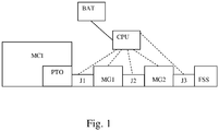
figure 1 shows a general outline of the traction system of the vehicle that is object of the present invention; -
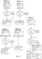
figure 2 shows flow diagrams of the operating modes of the system. - In the figures the same reference numbers and letters identify the same elements or components.
- With reference to
figure 1 , where a preferred implementation of the present invention is schematized, an internal combustion engine MCI is provided with a power takeoff to which a first electric motor-generator MG1 is connected by means of a controllable transmission joint J1. - The power takeoff can be of any type, for example the front one, namely the one to which auxiliary devices that absorb low levels of torque are connected, usually by means of pulleys.
- The rear power takeoff, on the contrary, is the one to which relevant loads are generally connected, such as oil pumps, compressor of the air necessary to control the suspensions and/or the braking system and additional devices according to the vehicle equipment. In this case, the torque/power absorbed by the auxiliary services can also exceed 50% of the one deliverable by the engine.
- The mark FSS indicates the auxiliary services with both high torque/power absorption and low power/torque absorption without distinction. In other words, the configuration described here can be obtained by means of both the front and the rear power takeoff of the internal combustion engine.
- The electric motor-generator MG1 can be connected directly to control the on-board auxiliary devices or the aforementioned oil pumps, for example by a fixed or a controllable joint (not shown). Thus it may have a shaft with two opposite ends, of which at least one is accessible, of which a first end is connectable to the PTO of the internal combustion engine and, for example, a second end is connected or connectable to the auxiliary services (or to the oil sumps generally connected to the rear power takeoff).
- According to another preferred alternative embodiment of the invention, the shaft of the motor-generator MG1 is connected by a first end to the PTO of the internal combustion engine and by a second end to a second electric motor-generator MG2 by means of a second controllable joint J2.
- Therefore, the shaft of the second motor-generator MG2 comprises a first end connectable with the tree of the first motor-generator and a second end connected or connectable to the auxiliary services. Thus, the second end has a fixed or a controllable joint J3 for the connection to the on-board auxiliary devices.
- Among the auxiliary devices there can be, for example, the compressor of the air conditioning, the pump of the hydraulic power steering, the fan of the radiator, the water pump, the air compressor, the vacuum pump, etc..
- The joints J1, J2 and J3 can be made by means of transmission systems of the type belt/pulley, either by means of hydraulic or electromagnetic or pneumatic clutches, hydraulic or electromagnetic or pneumatic joints, or by means of gear transmissions.
- One or more batteries BAT or similar devices are arranged to store electric energy and, similarly, one or more electric energy converters can be provided both to generate electric energy to be stored, and to guide the electric motors MG1 and MG2 using the energy stored.
- In the following, the operating modes of the system that is object of the present invention are described, in relation to the control of the joint(s) and of the motor-generator(s):
- 1) Mode 1.1, called "cold starting": with the vehicle initially stopped and the internal combustion engine MCI initially switched off,
- joints J1 and J2, if the second motor-generator MG2 is present, is/are closed or kept closed and J3, if controllable, is open or kept open, to reduce the resistant torque provided to the motor-generator(s)
- the two motor-generators MG1 and MG2 (if also the second motor-generator MG2 is present) are activated together as electric motors to start the internal combustion engine.
With reference tofigure 2 :- step 111: acquisition of the operating conditions of the vehicle, in particular, condition of the engine MCI and temperature, for example, of the coolant, if the engine is switched off, cold and has to be started,
- step 112: closing of J1 and J2,
- step 113: verification if J3 is controllable,
step 114 opening of J3,- otherwise: step 115 use of both motors MG1, MG2 as motors to start MCI.
- 2) Mode 1.2, called "normal with smart motor-generators": with internal combustion engine MCI activated,
- joints J1, J2, J3 are closed
- the two motor-generators MG1 and MG2 (if also the second motor-generator MG2 is present) work as generators providing resistant torque to the heat engine, that can vary as a function of the current electric loads or also in relation to the remaining traction torque of the heat engine itself or also in relation to the occurrence of a braking condition with engine brake, realizing a so called regenerative braking. In such operating conditions, also the auxiliaries are driven by the internal combustion engine proportionally to the revolutions per minute of the engine.
figure 2 :- step 121: acquisition of the operating conditions of the vehicle, in particular, condition of the engine MCI and temperature, for example, of the coolant, if the engine is started and, for example, the vehicle is braking,
- step 122: closing of J1 and J2,
- step 123: verification if J3 is controllable,
step 124 closing of J3,- otherwise:
step 125 use of both the engines MG1, MG2 as electric generators with control of the resistant torque offered as a function of the operating conditions of MCI.
- 3) Mode 2.1, called "electric auxiliaries": with internal combustion engine MCI deactivated, and vehicle (VH) in running conditions (ON),
- the first joint J1 and/or the second joint J2 is/are open or kept open, so that at least one electric motor can drive the auxiliary services being disconnected from the internal combustion engine MCI: if only one motor-generator is present, then J1 is open and the connection means with the services are closed, namely the electric motor drives the auxiliary services; on the contrary, if two motor-generators are present, then J2 can be open or closed in relation to the fact that the first motor generator can collaborate or not in driving the auxiliary services and J3, if controllable, is closed to drive the auxiliary services;
- the motor-generator (MG1 if it is the only motor-generator or) MG2 or both motor-generators are activated to drive, by means of the joint J3 and possibly also J2, the auxiliary services. Thus J2 is generally open unless the resistant torque provided by the services is such as to require the intervention of also the first motor-generator MG1, to assist the second MG2.
With reference tofigure 2 :- step 211: acquisition of the operating conditions of the engine, in particular, condition of the engine MCI if the engine is switched off, if the vehicle is running, or if the functioning of the auxiliary services is necessary,
- step 212: opening of J1 and J2,
- step 213: verification if J3 is controllable,
step 214 closing of J3,- otherwise:
step 215 use of at least MG2 as motor to drive the auxiliary services, or, if the torque required is too high, closing of also J2 and use of both the motor-generators MG1 and MG2 as motors to drive the auxiliary services.
- 4) Mode 2.2, called "hot starting or minimum hybrid activity": the internal combustion engine MCI is initially stopped and hot, namely having been switched off for a short time and it is necessary to restart it, or it is started and it is necessary to assist it: minimum hybrid functioning:
- the first joint J1 is closed, while the second joint J2 is open, the conditions of the third joint are not relevant, unless the mode 2.1 is running, in this case, if the third joint is controllable, then it is closed;
- the motor-generator MG1 by means of the first joint J1 provides for the internal combustion engine starting.
With reference tofigure 2 :- step 221: acquisition of the operating conditions of the vehicle, in particular, condition of the engine MCI and temperature, for example, of the coolant, if the engine is switched off, hot and it has to be started, or it is started and it has to be assisted,
- step 222: closing of J1 and opening of J2,
- step 223: use of MG1 to start or to assist the internal combustion engine MCI.
- 5) Mode 2.3, called "smart electric auxiliaries & smart motor-generator", with internal combustion engine MCI started
- the first joint J1 is closed, the second joint is open and the third joint J3 is closed;
- the first motor-generator MG1 works as generator receiving torque from the internal combustion engine by means of the first joint J1 or it works as motor assisting the internal combustion engine in minimum hybrid mode, while the second motor-generator MG2 provides for driving the auxiliaries at a speed independent of the internal combustion engine by means of the third joint J3, offering an optimized transmission of the mechanical energy to the auxiliaries that can operate at an optimal speed.
The joint J2 can be closed, in these operating modes, only when the speed of rotation of the internal combustion engine corresponds to said optimal speed needed by said on-board auxiliary devices.
If the joint J2 is open, the second motor-generator works as a motor, otherwise as a generator.
Thanks to the configuration with two motor-generators and with at least the controllable joints J1 and J2 it is possible to correlate the speed of rotation of the auxiliary services to the speed of rotation of the internal combustion engine. In particular, when the speed of rotation of the engine is optimal for the auxiliary services, then the joint J2 is closed and both the motor-generators work as generators.
With reference tofigure 2 :- step 231 acquisition of the operating conditions of the vehicle, in particular, condition of the engine MCI and speed of rotation of the engine,
- step 232: closing of J1,
- step 233: verification if J3 is controllable,
step 234 closing of J3,- otherwise: step 235: verification if the speed of rotation if optimal for the auxiliary services,
- if it is optimal:
- step 236: closing of J2 and
- step 237: use of MG1 and/or MG2 as motors to assist the internal combustion engine or as generators to generate electric energy in relation to the operating conditions of the internal combustion engine,
- if it is not optimal:
- step 238: opening of J2,
- step 239: use of MG2 as motor to drive the auxiliary services and of MG2 as motor to assist the internal combustion engine or as generator to generate electric energy in relation to the operating conditions of the internal combustion engine.
The different operating modes described above can be managed by one of the on-board control units of the vehicle, such as, for example, a vehicular control unit CPU, to appropriately select the modes 1.1 or 2.1 or 2.2 or 2.3 controlling, in accordance to what described above, the joints J1, J2 and J3 and the operating mode of MG1 and MG2.
Preferably, the same vehicular control unit which manages the system S&S, hybrid or bimodal, is configured to manage the aforementioned operating modes and the respective states of the system. - Preferably, the motor-generator MG1 or the motor-generators MG1 and MG2 are the only electric machines connected to the internal combustion engine.
- It will be apparent to the person skilled in the art that other alternative and equivalent embodiments of the invention can be conceived and reduced to practice without departing from the scope of the invention.
- From the description set forth above it will be possible for the person skilled in the art to embody the invention with no need of describing further construction details. The elements and the characteristics described in the different preferred embodiments may be combined without departing from the scope of the present application. What is described in the description of the prior art, if not explicitly excluded in the detailed description, has to be considered in combination with the characteristics of the present invention, forming an integral part of the present invention.
Claims (11)
- A land vehicle comprising:- an internal combustion engine (MCI) provided with power take-off (PTO),- electrical energy storage means (BAT),- a first electric motor-generator (MG1) having a shaft connected to said power take-off (PTO) by means of a controllable joint (J1) and to auxiliary on-board devices (FSS) by means of further connection means (J2, MG2, J3),- control means (CPU) of said first controllable joint (J1) of said electric motor-generator (MG1) and of said connection means (J2, MG2, J3)Characterized in that
said further connection means (J2, MG2, J3) comprise:- a second controllable joint (J2),- a third fixed or controllable joint (J3),- a second motor-generator (MG2) having a respective shaft:• connected to said shaft of said first motor-generator (MG1) by means of said second controllable joint,• connected to said auxiliary on-board devices by means of said third joint (J3). - A vehicle according to claim 1, wherein said control means (CPU) are configured to manage the internal combustion engine in Stop & Start mode and/or hybrid and/or bimodal mode, and when the engine is in Stop mode, are configured to:- open said first joint (J1),- close or keep closed said further connection means (J2, MG2, J3),- activate said first electric motor-generator (MG1) as electric motor to operate said auxiliary on-board devices.
- A vehicle according to claim 2, wherein said control means (CPU) are further configured, before starting the internal combustion engine, to:- close said first joint (J2),- optionally open said further connection means (J2, MG2, J3),- activate said electric motor-generator (MG1) as electric motor.
- A vehicle according to claim 1, wherein said control means (CPU) are configured to:- open said second joint (J2),- activate said second electric motor-generator (MG1) as electric motor to operate said auxiliary on-board devices (Mode 2.1).
- A vehicle according to claim 1, wherein said control means (CPU) are configured to manage the internal combustion engine in Stop & Start mode and/or hybrid and/or bimodal mode, and, before hot-starting the internal combustion engine, are further configured to:- close or keep closed said first joint (J1),- open or keep open said second joint (J2),- activate said first electric motor-generator (MG1) as electric motor (Mode 2.2).
- A vehicle according to claim 1, wherein, when the internal combustion engine (MCI) is active, said control means (CPU) are configured to:- acquire a revolution speed of the internal combustion engine and check whether said speed is an optimal speed for said auxiliary services, then if said speed is not optimal the control means are configured to:- close or keep closed said first and third joint (J1,J3) if said third joint is controllable,- open or keep open said second joint (J2),- control the first motor-generator (MG1) to make it work either as motor to assist the internal combustion engine (MCI) or as generator,- control the second motor-generator (MG2) to make it work as motor (Mode 2.3),if instead said motor speed (MCI) is optimal for the auxiliary services, then the control means are configured to:- close or keep closed said first, second and third joint (J1,J2,J3) if said third joint is controllable,- control the first and the second motor-generator (MG1, MG2) so that they can work either as motors to assist the internal combustion engine (MCI) or as generators (Mode 1.2).
- A vehicle according to claim 1, wherein, when the internal combustion engine (MCI) is off and cold, said control means (CPU) are configured to:- close or keep closed said first and second joint (J1, J2),- optionally open or keep open said third joint (J3), if controllable,- control said first and second motor-generator (MG1, MG2) to make them work as motors to start said internal combustion engine (Mode 1.1).
- A vehicle according to any one of the preceding claims, wherein one of said joints (J1, J2, J3) is:- a hydraulic, electromagnetic or pneumatic clutch, and/or- an electromagnetic or pneumatic hydraulic joint
- A vehicle according to any one of the preceding claims, wherein both ends of the respective shaft of one of said motor-generators (MG1) are accessible, having a first end connected to a controllable joint (J1, J2) and a second end connected to another fixed or controllable joint (J2,J3).
- A vehicle according to any one of the preceding claims from 1 to 8, wherein both ends of the respective shaft of a first of said motor-generators (MG1) are accessible, having a first end connected to a controllable joint (J1) and a second end connected to another controllable joint (J2), and both ends of a respective shaft of a second motor-generator (MG2) are accessible, having a first end connected to said controllable joint (J2) and a second end connected to another fixed or controllable joint (J3).
- A vehicle according to one of the preceding claims wherein said first motor-generator (MG1) is connected to a front or rear power take-off (PTO) of the internal combustion engine (MCI).
Applications Claiming Priority (1)
| Application Number | Priority Date | Filing Date | Title |
|---|---|---|---|
| IT001312A ITMI20131312A1 (en) | 2013-08-02 | 2013-08-02 | TERRESTRIAL VEHICLE WITH INTERNAL COMBUSTION ENGINE AND AUXILIARY DEVICES |
Publications (2)
| Publication Number | Publication Date |
|---|---|
| EP2832575A1 EP2832575A1 (en) | 2015-02-04 |
| EP2832575B1 true EP2832575B1 (en) | 2017-11-22 |
Family
ID=49304120
Family Applications (1)
| Application Number | Title | Priority Date | Filing Date |
|---|---|---|---|
| EP14179465.1A Active EP2832575B1 (en) | 2013-08-02 | 2014-08-01 | Terrestrial vehicle with internal combustion engine and auxiliary devices |
Country Status (3)
| Country | Link |
|---|---|
| EP (1) | EP2832575B1 (en) |
| ES (1) | ES2659520T3 (en) |
| IT (1) | ITMI20131312A1 (en) |
Family Cites Families (6)
| Publication number | Priority date | Publication date | Assignee | Title |
|---|---|---|---|---|
| DE4225315C2 (en) * | 1992-07-31 | 1995-07-20 | Man Nutzfahrzeuge Ag | Hybrid drive for vehicles |
| JP4682416B2 (en) * | 2000-11-16 | 2011-05-11 | トヨタ自動車株式会社 | Vehicle drive device |
| DE102006013502A1 (en) * | 2006-03-23 | 2007-09-27 | Siemens Ag | Drive device with a mechanically driven auxiliary unit, method for operating the drive device and means for carrying out the method |
| US7547264B2 (en) * | 2006-08-14 | 2009-06-16 | Gm Global Technology Operations, Inc. | Starter alternator accessory drive system for a hybrid vehicle |
| WO2013004595A1 (en) * | 2011-07-07 | 2013-01-10 | Kasi Technologies Ab | Hybrid system comprising a supercharging system and method for operation |
| US9856781B2 (en) * | 2011-09-30 | 2018-01-02 | Eaton Corporation | Supercharger assembly with independent superchargers and motor/generator |
-
2013
- 2013-08-02 IT IT001312A patent/ITMI20131312A1/en unknown
-
2014
- 2014-08-01 EP EP14179465.1A patent/EP2832575B1/en active Active
- 2014-08-01 ES ES14179465.1T patent/ES2659520T3/en active Active
Non-Patent Citations (1)
| Title |
|---|
| None * |
Also Published As
| Publication number | Publication date |
|---|---|
| EP2832575A1 (en) | 2015-02-04 |
| ITMI20131312A1 (en) | 2015-02-03 |
| ES2659520T3 (en) | 2018-03-16 |
Similar Documents
| Publication | Publication Date | Title |
|---|---|---|
| US10259448B2 (en) | Hybrid vehicle propulsion systems and methods | |
| US10189470B2 (en) | Hybrid vehicle propulsion systems and methods | |
| US8818588B2 (en) | Parallel hybrid drive system utilizing power take off connection as transfer for a secondary energy source | |
| US8057355B2 (en) | Hydraulic control system for multi-mode hybrid transmission and method of regulating the same | |
| US8187147B2 (en) | Hydraulic control system for multi-mode hybrid transmission and method of regulating the same | |
| EP3309032B1 (en) | Energy management control device for hybrid vehicle | |
| EP3086966B1 (en) | A method of starting a vehicle with power balance | |
| US10093166B2 (en) | Power generation control system for hybrid vehicle | |
| KR101846809B1 (en) | A shift control device of a vehicle | |
| CN101643021A (en) | Hybrid electric vehicle powertrain with an all electric drive mode | |
| JP2011000978A (en) | Auxiliary pump driving controller | |
| US20160069231A1 (en) | Control system for electric vehicle | |
| JP2016527428A (en) | Turbocharger | |
| CN204895102U (en) | Torque coupling and rotational speed coupling driving system | |
| EP2832575A1 (en) | Terrestrial vehicle with internal combustion engine and auxiliary devices | |
| JP2010143513A (en) | Hydraulic circuit structure of transmission | |
| JP6167585B2 (en) | Hybrid vehicle drive device | |
| JP2013185599A (en) | Hydraulic control device of clutch | |
| JP2019537539A (en) | Method and apparatus for preliminary driving of a vehicle | |
| CN109328276B (en) | Hydraulic control device of the pressure accumulator of the actuator of the transmission of the hybrid drive train of the vehicle |
Legal Events
| Date | Code | Title | Description |
|---|---|---|---|
| 17P | Request for examination filed |
Effective date: 20140801 |
|
| AK | Designated contracting states |
Kind code of ref document: A1 Designated state(s): AL AT BE BG CH CY CZ DE DK EE ES FI FR GB GR HR HU IE IS IT LI LT LU LV MC MK MT NL NO PL PT RO RS SE SI SK SM TR |
|
| AX | Request for extension of the european patent |
Extension state: BA ME |
|
| PUAI | Public reference made under article 153(3) epc to a published international application that has entered the european phase |
Free format text: ORIGINAL CODE: 0009012 |
|
| R17P | Request for examination filed (corrected) |
Effective date: 20150731 |
|
| RBV | Designated contracting states (corrected) |
Designated state(s): AL AT BE BG CH CY CZ DE DK EE ES FI FR GB GR HR HU IE IS IT LI LT LU LV MC MK MT NL NO PL PT RO RS SE SI SK SM TR |
|
| REG | Reference to a national code |
Ref country code: DE Ref legal event code: R079 Ref document number: 602014017476 Country of ref document: DE Free format text: PREVIOUS MAIN CLASS: B60K0017280000 Ipc: F02N0011040000 |
|
| GRAP | Despatch of communication of intention to grant a patent |
Free format text: ORIGINAL CODE: EPIDOSNIGR1 |
|
| RIC1 | Information provided on ipc code assigned before grant |
Ipc: F02N 15/02 20060101ALI20170428BHEP Ipc: F02N 11/04 20060101AFI20170428BHEP Ipc: B60K 25/00 20060101ALI20170428BHEP Ipc: F02N 11/00 20060101ALI20170428BHEP |
|
| INTG | Intention to grant announced |
Effective date: 20170526 |
|
| GRAS | Grant fee paid |
Free format text: ORIGINAL CODE: EPIDOSNIGR3 |
|
| GRAJ | Information related to disapproval of communication of intention to grant by the applicant or resumption of examination proceedings by the epo deleted |
Free format text: ORIGINAL CODE: EPIDOSDIGR1 |
|
| GRAL | Information related to payment of fee for publishing/printing deleted |
Free format text: ORIGINAL CODE: EPIDOSDIGR3 |
|
| GRAR | Information related to intention to grant a patent recorded |
Free format text: ORIGINAL CODE: EPIDOSNIGR71 |
|
| GRAA | (expected) grant |
Free format text: ORIGINAL CODE: 0009210 |
|
| INTC | Intention to grant announced (deleted) | ||
| RAP1 | Party data changed (applicant data changed or rights of an application transferred) |
Owner name: ALTRA S.P.A. |
|
| AK | Designated contracting states |
Kind code of ref document: B1 Designated state(s): AL AT BE BG CH CY CZ DE DK EE ES FI FR GB GR HR HU IE IS IT LI LT LU LV MC MK MT NL NO PL PT RO RS SE SI SK SM TR |
|
| INTG | Intention to grant announced |
Effective date: 20171016 |
|
| REG | Reference to a national code |
Ref country code: GB Ref legal event code: FG4D |
|
| REG | Reference to a national code |
Ref country code: CH Ref legal event code: EP |
|
| REG | Reference to a national code |
Ref country code: IE Ref legal event code: FG4D |
|
| REG | Reference to a national code |
Ref country code: AT Ref legal event code: REF Ref document number: 948650 Country of ref document: AT Kind code of ref document: T Effective date: 20171215 |
|
| REG | Reference to a national code |
Ref country code: DE Ref legal event code: R096 Ref document number: 602014017476 Country of ref document: DE |
|
| REG | Reference to a national code |
Ref country code: NL Ref legal event code: FP |
|
| REG | Reference to a national code |
Ref country code: SE Ref legal event code: TRGR |
|
| REG | Reference to a national code |
Ref country code: CH Ref legal event code: NV Representative=s name: PATENTANWAELTE SCHAAD, BALASS, MENZL AND PARTN, CH |
|
| REG | Reference to a national code |
Ref country code: ES Ref legal event code: FG2A Ref document number: 2659520 Country of ref document: ES Kind code of ref document: T3 Effective date: 20180316 |
|
| REG | Reference to a national code |
Ref country code: LT Ref legal event code: MG4D |
|
| REG | Reference to a national code |
Ref country code: AT Ref legal event code: MK05 Ref document number: 948650 Country of ref document: AT Kind code of ref document: T Effective date: 20171122 |
|
| PG25 | Lapsed in a contracting state [announced via postgrant information from national office to epo] |
Ref country code: FI Free format text: LAPSE BECAUSE OF FAILURE TO SUBMIT A TRANSLATION OF THE DESCRIPTION OR TO PAY THE FEE WITHIN THE PRESCRIBED TIME-LIMIT Effective date: 20171122 Ref country code: LT Free format text: LAPSE BECAUSE OF FAILURE TO SUBMIT A TRANSLATION OF THE DESCRIPTION OR TO PAY THE FEE WITHIN THE PRESCRIBED TIME-LIMIT Effective date: 20171122 Ref country code: NO Free format text: LAPSE BECAUSE OF FAILURE TO SUBMIT A TRANSLATION OF THE DESCRIPTION OR TO PAY THE FEE WITHIN THE PRESCRIBED TIME-LIMIT Effective date: 20180222 |
|
| PG25 | Lapsed in a contracting state [announced via postgrant information from national office to epo] |
Ref country code: GR Free format text: LAPSE BECAUSE OF FAILURE TO SUBMIT A TRANSLATION OF THE DESCRIPTION OR TO PAY THE FEE WITHIN THE PRESCRIBED TIME-LIMIT Effective date: 20180223 Ref country code: RS Free format text: LAPSE BECAUSE OF FAILURE TO SUBMIT A TRANSLATION OF THE DESCRIPTION OR TO PAY THE FEE WITHIN THE PRESCRIBED TIME-LIMIT Effective date: 20171122 Ref country code: LV Free format text: LAPSE BECAUSE OF FAILURE TO SUBMIT A TRANSLATION OF THE DESCRIPTION OR TO PAY THE FEE WITHIN THE PRESCRIBED TIME-LIMIT Effective date: 20171122 Ref country code: HR Free format text: LAPSE BECAUSE OF FAILURE TO SUBMIT A TRANSLATION OF THE DESCRIPTION OR TO PAY THE FEE WITHIN THE PRESCRIBED TIME-LIMIT Effective date: 20171122 Ref country code: BG Free format text: LAPSE BECAUSE OF FAILURE TO SUBMIT A TRANSLATION OF THE DESCRIPTION OR TO PAY THE FEE WITHIN THE PRESCRIBED TIME-LIMIT Effective date: 20180222 Ref country code: AT Free format text: LAPSE BECAUSE OF FAILURE TO SUBMIT A TRANSLATION OF THE DESCRIPTION OR TO PAY THE FEE WITHIN THE PRESCRIBED TIME-LIMIT Effective date: 20171122 |
|
| PG25 | Lapsed in a contracting state [announced via postgrant information from national office to epo] |
Ref country code: EE Free format text: LAPSE BECAUSE OF FAILURE TO SUBMIT A TRANSLATION OF THE DESCRIPTION OR TO PAY THE FEE WITHIN THE PRESCRIBED TIME-LIMIT Effective date: 20171122 Ref country code: DK Free format text: LAPSE BECAUSE OF FAILURE TO SUBMIT A TRANSLATION OF THE DESCRIPTION OR TO PAY THE FEE WITHIN THE PRESCRIBED TIME-LIMIT Effective date: 20171122 Ref country code: CZ Free format text: LAPSE BECAUSE OF FAILURE TO SUBMIT A TRANSLATION OF THE DESCRIPTION OR TO PAY THE FEE WITHIN THE PRESCRIBED TIME-LIMIT Effective date: 20171122 Ref country code: SK Free format text: LAPSE BECAUSE OF FAILURE TO SUBMIT A TRANSLATION OF THE DESCRIPTION OR TO PAY THE FEE WITHIN THE PRESCRIBED TIME-LIMIT Effective date: 20171122 Ref country code: CY Free format text: LAPSE BECAUSE OF FAILURE TO SUBMIT A TRANSLATION OF THE DESCRIPTION OR TO PAY THE FEE WITHIN THE PRESCRIBED TIME-LIMIT Effective date: 20171122 |
|
| REG | Reference to a national code |
Ref country code: DE Ref legal event code: R097 Ref document number: 602014017476 Country of ref document: DE |
|
| REG | Reference to a national code |
Ref country code: FR Ref legal event code: PLFP Year of fee payment: 5 |
|
| PG25 | Lapsed in a contracting state [announced via postgrant information from national office to epo] |
Ref country code: RO Free format text: LAPSE BECAUSE OF FAILURE TO SUBMIT A TRANSLATION OF THE DESCRIPTION OR TO PAY THE FEE WITHIN THE PRESCRIBED TIME-LIMIT Effective date: 20171122 Ref country code: PL Free format text: LAPSE BECAUSE OF FAILURE TO SUBMIT A TRANSLATION OF THE DESCRIPTION OR TO PAY THE FEE WITHIN THE PRESCRIBED TIME-LIMIT Effective date: 20171122 Ref country code: SM Free format text: LAPSE BECAUSE OF FAILURE TO SUBMIT A TRANSLATION OF THE DESCRIPTION OR TO PAY THE FEE WITHIN THE PRESCRIBED TIME-LIMIT Effective date: 20171122 |
|
| PLBE | No opposition filed within time limit |
Free format text: ORIGINAL CODE: 0009261 |
|
| STAA | Information on the status of an ep patent application or granted ep patent |
Free format text: STATUS: NO OPPOSITION FILED WITHIN TIME LIMIT |
|
| 26N | No opposition filed |
Effective date: 20180823 |
|
| PG25 | Lapsed in a contracting state [announced via postgrant information from national office to epo] |
Ref country code: SI Free format text: LAPSE BECAUSE OF FAILURE TO SUBMIT A TRANSLATION OF THE DESCRIPTION OR TO PAY THE FEE WITHIN THE PRESCRIBED TIME-LIMIT Effective date: 20171122 |
|
| PG25 | Lapsed in a contracting state [announced via postgrant information from national office to epo] |
Ref country code: MC Free format text: LAPSE BECAUSE OF FAILURE TO SUBMIT A TRANSLATION OF THE DESCRIPTION OR TO PAY THE FEE WITHIN THE PRESCRIBED TIME-LIMIT Effective date: 20171122 |
|
| PG25 | Lapsed in a contracting state [announced via postgrant information from national office to epo] |
Ref country code: LU Free format text: LAPSE BECAUSE OF NON-PAYMENT OF DUE FEES Effective date: 20180801 |
|
| REG | Reference to a national code |
Ref country code: BE Ref legal event code: MM Effective date: 20180831 |
|
| REG | Reference to a national code |
Ref country code: IE Ref legal event code: MM4A |
|
| PG25 | Lapsed in a contracting state [announced via postgrant information from national office to epo] |
Ref country code: IE Free format text: LAPSE BECAUSE OF NON-PAYMENT OF DUE FEES Effective date: 20180801 |
|
| PG25 | Lapsed in a contracting state [announced via postgrant information from national office to epo] |
Ref country code: BE Free format text: LAPSE BECAUSE OF NON-PAYMENT OF DUE FEES Effective date: 20180831 |
|
| PG25 | Lapsed in a contracting state [announced via postgrant information from national office to epo] |
Ref country code: MT Free format text: LAPSE BECAUSE OF NON-PAYMENT OF DUE FEES Effective date: 20180801 |
|
| REG | Reference to a national code |
Ref country code: DE Ref legal event code: R082 Ref document number: 602014017476 Country of ref document: DE Representative=s name: TERPATENT PARTGMBB, DE Ref country code: DE Ref legal event code: R082 Ref document number: 602014017476 Country of ref document: DE Representative=s name: TERPATENT PATENTANWAELTE TER SMITTEN EBERLEIN-, DE |
|
| PG25 | Lapsed in a contracting state [announced via postgrant information from national office to epo] |
Ref country code: TR Free format text: LAPSE BECAUSE OF FAILURE TO SUBMIT A TRANSLATION OF THE DESCRIPTION OR TO PAY THE FEE WITHIN THE PRESCRIBED TIME-LIMIT Effective date: 20171122 |
|
| PG25 | Lapsed in a contracting state [announced via postgrant information from national office to epo] |
Ref country code: HU Free format text: LAPSE BECAUSE OF FAILURE TO SUBMIT A TRANSLATION OF THE DESCRIPTION OR TO PAY THE FEE WITHIN THE PRESCRIBED TIME-LIMIT; INVALID AB INITIO Effective date: 20140801 Ref country code: PT Free format text: LAPSE BECAUSE OF FAILURE TO SUBMIT A TRANSLATION OF THE DESCRIPTION OR TO PAY THE FEE WITHIN THE PRESCRIBED TIME-LIMIT Effective date: 20171122 |
|
| PG25 | Lapsed in a contracting state [announced via postgrant information from national office to epo] |
Ref country code: MK Free format text: LAPSE BECAUSE OF NON-PAYMENT OF DUE FEES Effective date: 20171122 |
|
| PG25 | Lapsed in a contracting state [announced via postgrant information from national office to epo] |
Ref country code: IS Free format text: LAPSE BECAUSE OF FAILURE TO SUBMIT A TRANSLATION OF THE DESCRIPTION OR TO PAY THE FEE WITHIN THE PRESCRIBED TIME-LIMIT Effective date: 20180322 Ref country code: AL Free format text: LAPSE BECAUSE OF FAILURE TO SUBMIT A TRANSLATION OF THE DESCRIPTION OR TO PAY THE FEE WITHIN THE PRESCRIBED TIME-LIMIT Effective date: 20171122 |
|
| P01 | Opt-out of the competence of the unified patent court (upc) registered |
Effective date: 20230519 |
|
| PGFP | Annual fee paid to national office [announced via postgrant information from national office to epo] |
Ref country code: NL Payment date: 20250825 Year of fee payment: 12 |
|
| PGFP | Annual fee paid to national office [announced via postgrant information from national office to epo] |
Ref country code: ES Payment date: 20250916 Year of fee payment: 12 |
|
| PGFP | Annual fee paid to national office [announced via postgrant information from national office to epo] |
Ref country code: DE Payment date: 20250827 Year of fee payment: 12 |
|
| PGFP | Annual fee paid to national office [announced via postgrant information from national office to epo] |
Ref country code: IT Payment date: 20250714 Year of fee payment: 12 |
|
| PGFP | Annual fee paid to national office [announced via postgrant information from national office to epo] |
Ref country code: GB Payment date: 20250826 Year of fee payment: 12 |
|
| PGFP | Annual fee paid to national office [announced via postgrant information from national office to epo] |
Ref country code: FR Payment date: 20250825 Year of fee payment: 12 |
|
| PGFP | Annual fee paid to national office [announced via postgrant information from national office to epo] |
Ref country code: CH Payment date: 20250901 Year of fee payment: 12 Ref country code: SE Payment date: 20250825 Year of fee payment: 12 |