EP2832524A1 - Blow molding device - Google Patents
Blow molding device Download PDFInfo
- Publication number
- EP2832524A1 EP2832524A1 EP20130770370 EP13770370A EP2832524A1 EP 2832524 A1 EP2832524 A1 EP 2832524A1 EP 20130770370 EP20130770370 EP 20130770370 EP 13770370 A EP13770370 A EP 13770370A EP 2832524 A1 EP2832524 A1 EP 2832524A1
- Authority
- EP
- European Patent Office
- Prior art keywords
- preform
- blow nozzle
- tubular portion
- blow
- mouth
- Prior art date
- Legal status (The legal status is an assumption and is not a legal conclusion. Google has not performed a legal analysis and makes no representation as to the accuracy of the status listed.)
- Granted
Links
Images

Classifications
-
- B—PERFORMING OPERATIONS; TRANSPORTING
- B29—WORKING OF PLASTICS; WORKING OF SUBSTANCES IN A PLASTIC STATE IN GENERAL
- B29C—SHAPING OR JOINING OF PLASTICS; SHAPING OF MATERIAL IN A PLASTIC STATE, NOT OTHERWISE PROVIDED FOR; AFTER-TREATMENT OF THE SHAPED PRODUCTS, e.g. REPAIRING
- B29C49/00—Blow-moulding, i.e. blowing a preform or parison to a desired shape within a mould; Apparatus therefor
- B29C49/28—Blow-moulding apparatus
-
- B—PERFORMING OPERATIONS; TRANSPORTING
- B29—WORKING OF PLASTICS; WORKING OF SUBSTANCES IN A PLASTIC STATE IN GENERAL
- B29C—SHAPING OR JOINING OF PLASTICS; SHAPING OF MATERIAL IN A PLASTIC STATE, NOT OTHERWISE PROVIDED FOR; AFTER-TREATMENT OF THE SHAPED PRODUCTS, e.g. REPAIRING
- B29C49/00—Blow-moulding, i.e. blowing a preform or parison to a desired shape within a mould; Apparatus therefor
- B29C49/08—Biaxial stretching during blow-moulding
- B29C49/10—Biaxial stretching during blow-moulding using mechanical means for prestretching
- B29C49/12—Stretching rods
-
- B—PERFORMING OPERATIONS; TRANSPORTING
- B29—WORKING OF PLASTICS; WORKING OF SUBSTANCES IN A PLASTIC STATE IN GENERAL
- B29C—SHAPING OR JOINING OF PLASTICS; SHAPING OF MATERIAL IN A PLASTIC STATE, NOT OTHERWISE PROVIDED FOR; AFTER-TREATMENT OF THE SHAPED PRODUCTS, e.g. REPAIRING
- B29C49/00—Blow-moulding, i.e. blowing a preform or parison to a desired shape within a mould; Apparatus therefor
- B29C49/42—Component parts, details or accessories; Auxiliary operations
- B29C49/46—Component parts, details or accessories; Auxiliary operations characterised by using particular environment or blow fluids other than air
-
- B—PERFORMING OPERATIONS; TRANSPORTING
- B29—WORKING OF PLASTICS; WORKING OF SUBSTANCES IN A PLASTIC STATE IN GENERAL
- B29C—SHAPING OR JOINING OF PLASTICS; SHAPING OF MATERIAL IN A PLASTIC STATE, NOT OTHERWISE PROVIDED FOR; AFTER-TREATMENT OF THE SHAPED PRODUCTS, e.g. REPAIRING
- B29C49/00—Blow-moulding, i.e. blowing a preform or parison to a desired shape within a mould; Apparatus therefor
- B29C49/42—Component parts, details or accessories; Auxiliary operations
- B29C49/58—Blowing means
-
- B—PERFORMING OPERATIONS; TRANSPORTING
- B29—WORKING OF PLASTICS; WORKING OF SUBSTANCES IN A PLASTIC STATE IN GENERAL
- B29C—SHAPING OR JOINING OF PLASTICS; SHAPING OF MATERIAL IN A PLASTIC STATE, NOT OTHERWISE PROVIDED FOR; AFTER-TREATMENT OF THE SHAPED PRODUCTS, e.g. REPAIRING
- B29C49/00—Blow-moulding, i.e. blowing a preform or parison to a desired shape within a mould; Apparatus therefor
- B29C49/42—Component parts, details or accessories; Auxiliary operations
- B29C2049/4294—Sealing means
-
- B—PERFORMING OPERATIONS; TRANSPORTING
- B29—WORKING OF PLASTICS; WORKING OF SUBSTANCES IN A PLASTIC STATE IN GENERAL
- B29C—SHAPING OR JOINING OF PLASTICS; SHAPING OF MATERIAL IN A PLASTIC STATE, NOT OTHERWISE PROVIDED FOR; AFTER-TREATMENT OF THE SHAPED PRODUCTS, e.g. REPAIRING
- B29C49/00—Blow-moulding, i.e. blowing a preform or parison to a desired shape within a mould; Apparatus therefor
- B29C49/42—Component parts, details or accessories; Auxiliary operations
- B29C49/46—Component parts, details or accessories; Auxiliary operations characterised by using particular environment or blow fluids other than air
- B29C2049/4602—Blowing fluids
- B29C2049/465—Blowing fluids being incompressible
- B29C2049/4664—Blowing fluids being incompressible staying in the final article
-
- B—PERFORMING OPERATIONS; TRANSPORTING
- B29—WORKING OF PLASTICS; WORKING OF SUBSTANCES IN A PLASTIC STATE IN GENERAL
- B29C—SHAPING OR JOINING OF PLASTICS; SHAPING OF MATERIAL IN A PLASTIC STATE, NOT OTHERWISE PROVIDED FOR; AFTER-TREATMENT OF THE SHAPED PRODUCTS, e.g. REPAIRING
- B29C2949/00—Indexing scheme relating to blow-moulding
- B29C2949/07—Preforms or parisons characterised by their configuration
- B29C2949/0715—Preforms or parisons characterised by their configuration the preform having one end closed
-
- B—PERFORMING OPERATIONS; TRANSPORTING
- B29—WORKING OF PLASTICS; WORKING OF SUBSTANCES IN A PLASTIC STATE IN GENERAL
- B29C—SHAPING OR JOINING OF PLASTICS; SHAPING OF MATERIAL IN A PLASTIC STATE, NOT OTHERWISE PROVIDED FOR; AFTER-TREATMENT OF THE SHAPED PRODUCTS, e.g. REPAIRING
- B29C49/00—Blow-moulding, i.e. blowing a preform or parison to a desired shape within a mould; Apparatus therefor
- B29C49/02—Combined blow-moulding and manufacture of the preform or the parison
- B29C49/06—Injection blow-moulding
-
- B—PERFORMING OPERATIONS; TRANSPORTING
- B29—WORKING OF PLASTICS; WORKING OF SUBSTANCES IN A PLASTIC STATE IN GENERAL
- B29L—INDEXING SCHEME ASSOCIATED WITH SUBCLASS B29C, RELATING TO PARTICULAR ARTICLES
- B29L2031/00—Other particular articles
- B29L2031/712—Containers; Packaging elements or accessories, Packages
- B29L2031/7158—Bottles
Definitions
- the present invention relates to a device for blow molding a synthetic resin bottle, the device using a liquid as a pressure medium.
- bottles with their numerous excellent characteristics, numerous blow molded bottles, in particular, bottles (so-called pet bottles) that are made of polyethylene terephthalate (PET) resin and molded by biaxial stretch blow molding are heavily used as bottle containers in a variety of fields.
- PET polyethylene terephthalate
- Containers of such a kind are generally molded with use of a preform that has been inject-molded into a bottomed tubular shape like a test tube.
- the preform In a state where the preform is heated to a temperature at which a stretching effect is achieved, the preform is vertically stretched in an axis direction by means of a stretching rod and is inflated and stretched by means of blow air injected into the preform through a blow nozzle fitted tightly to a mouth tubular portion of the preform.
- Patent Literature 1 describes an invention directed to a method for molding a plastic bottle in which a preform is blow molded by means of a liquid supplied as the pressure medium through the blow nozzle instead of air.
- the liquid used as the pressure medium is water, tea, or a refreshing drink that is to be filled in the bottle as the product
- the process of filling the liquid product may be omitted, and a production line may be simplified.
- a bottomed tubular preform that has a test tube shape and that is made of a PET resin, except for the mouth tubular portion of the preform, is preheated to a temperature of substantially 100 °C to 120 °C that is suitable for stretch blow molding. Then, a pressurized liquid is supplied into the preform through the blow nozzle so as to inflate and stretch the preform, thus shaping the bottle.
- Liquid has greater heat capacity and greater heat conductivity with a preform than air, and depending on the temperature of the liquid supplied, the temperature of a circumferential wall of the preform is partly decreased. Accordingly, stretching unevenness occurs, resulting in the presence of non-uniform stretching ratio and thickness distribution and the appearance of residual strain in the circumferential wall of the bottle that is molded. As a result, problems such as the deteriorated stiffness, buckling strength, and heat resistance of the bottle, and the deformation of the molded bottle, might arise. In the extreme case, the preform is perforated with holes or the like during blow molding and may not be molded into a desired size.
- the present invention is to effectively prevent the occurrence of stretching unevenness during blow molding using a liquid as the pressure medium without significantly modifying the structure of the device.
- a first aspect of the present invention for solving the aforementioned problems resides in a blow molding device, including:
- the present inventors have investigated causes of the occurrence of stretching unevenness and a method for solving stretching unevenness and found that the main cause of stretching unevenness is that a large amount of liquid as the pressure medium that is ejected and supplied into the preform through the blow nozzle continuously collides with the circumferential wall located near right below the neck ring, and that the circumferential wall region is rapidly cooled from the temperature to which the preform is preheated for stretching.
- the present inventors have conceived the aforementioned structure, in particular, the structure of the blow nozzle.
- the engaging tubular piece has the length by which the lower end of the engaging tubular piece extends further downward than the neck ring in the state where the blow nozzle is in communication with the mouth tubular portion, the neck ring being provided around the lower end of the mouth tubular portion.
- the region located near right below the neck ring is a region shaped to be a shoulder portion of the bottle by blow molding, and when the region is rapidly cooled from the preheat temperature, the stretch property is deteriorated, and reduction in thickness due to stretching may not progress in the region shaped to be the shoulder portion of the bottle during shaping of the bottle, and accordingly, so-called material distribution from the above region to a region shaped to be a trunk portion and a bottom portion of the bottle is deteriorated. Consequently, the circumferential wall corresponding to the trunk portion and the bottom portion of the bottle may not be provided with a predetermined thickness, i.e., is reduced in thickness, and desired stiffness and buckling strength may not be achieved.
- the rapid decrease in temperature near right below the neck ring is prevented, and therefore, the deterioration in material distribution from the region shaped to be the shoulder portion of the bottle to the region shaped to be the trunk portion and the bottom portion of the bottle is limited.
- the thickness of the circumferential wall in the region corresponding to the trunk portion and the bottom portion falls within an assumed range.
- the thickness of the circumferential wall in the region corresponding to the trunk portion and the bottom portion falls within the assumed range, there is no need for further increasing the thickness of the preform for the purpose of achieving the desired stiffness and buckling strength. As a result, weight reduction of the bottle is achieved.
- the mouth tubular portion of the preform may be out of direct contact with the liquid, and accordingly, the mouth tubular portion is prevented from being deformed under pressure of the pressurized liquid.
- the extent of the length of the engaging tubular piece may be appropriately determined in consideration of conditions of blow molding or the like, including the degree of material distribution from the region corresponding to the shoulder portion to the region corresponding to the trunk portion and the bottom portion, the shape of the preform, and productivity, as long as the lower end of the engaging tubular piece extends further downward than the neck ring that is provided around the lower end of the mouth tubular portion.
- the length of the engaging tubular piece may be substantially 5 mm to 15 mm in order to achieve the advantageous effect. It should be noted, however, as the larger the length is, the more difficult it becomes to detach the nozzle from the mouth portion, it is preferable to determine an optimal range in consideration of the aforementioned various conditions.
- a second aspect of the present invention resides in the blow molding device according to the first aspect, wherein the blow nozzle is provided, on an outer circumferential wall thereof, with a circumferential stepped portion whose diameter is decreased toward a bottom thereof, and the blow nozzle is brought into the tight communication with the mouth tubular portion as a result of abutment between the circumferential stepped portion and an upper end surface of the mouth tubular portion via a seal member.
- the above structure concerns a way of sealing for bringing the blow nozzle into the tight communication with the mouth tubular portion.
- sealing performance is reliably maintained despite simplicity in structure, and the preform may be fitted or released from the fitting quickly. Besides, maintenance including exchange of the seal member may be easily implemented.
- the above structure concerning the way of sealing is merely an example, and any appropriate way of sealing may be adopted in consideration of sealing performance, productivity, or the like.
- a third aspect of the present invention resides in the blow molding device according to the first or the second aspect, wherein a stretching rod used for vertical stretching is inserted and disposed in the blow nozzle.
- the blow molding device is capable of preventing the liquid supplied into the preform from colliding with the circumferential wall located near right below the neck ring, and therefore, is capable of preventing and mitigating the rapid decrease in temperature in the circumferential wall region. Accordingly, the deterioration in material distribution from the region shaped to be the shoulder portion of the bottle to the region shaped to be the trunk portion and the bottom portion of the bottle is limited, and the thickness of the circumferential wall in the region corresponding to the trunk portion and the bottom portion falls within the assumed range. As a result, the bottle, although with an assumed weight, having the desired stiffness and buckling strength is achieved.
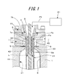
- FIG. 1 is a sectional view illustrating a part of a blow molding device according to one embodiment of the present invention in a state where a preform 31 is fitted to a metal mold 1 used for blow molding.
- the entire preform 31 has a bottomed cylindrical test tube shape.
- the preform 31 includes a mouth tubular portion 32 standing from an upper end portion of the preform 31, and the mouth tubular portion 32 is provided, on an outer circumferential wall of a lower end portion thereof, with a neck ring 33.
- the preform 31 is fitted in the metal mold 1, with the mouth tubular portion 32 being projected to an outside (upward in FIG. 1 ).
- the part of the device includes the metal mold 1, a partition wall member 11, a blow nozzle 4, a stretching rod 8, and a fixing block 15.
- a pressurized liquid supply device 21 is also provided to supply a pressurized liquid L used as a pressure medium for blow molding.
- the pressurized liquid supply device 21 may consist of a pressurizing device and a compressor serving as a power source for the pressurizing device.
- the pressurizing device is in the form of, for example, a plunger pump, or includes a cylinder with a built-in piston that includes two compartments.
- the partition wall member 11 is provided above the metal mold 1 such that the partition wall member 11 surrounds the outer circumferential surface of the mouth tubular portion 32 of the preform 31 projected upward of the metal mold 1 via the space S.
- the partition wall member 11 also includes a support flange piece 12 provided around a lower end portion of the partition wall member 11, and the support flange piece 12 tightly abuts against the neck ring 33 of the preform 31 from above so as to maintain a fitted position of the preform 31.
- the part of the device also includes an introduction path Fa for pressurized air that is later described.
- the blow nozzle 4 is a member that constitutes a supply path Fs for supplying, to an inside of the preform 31, the liquid L as the pressure medium that is supplied from the pressurized liquid supply device 21.
- the blow nozzle 4 according to the present embodiment has a tapered tubular shape including an upper portion whose diameter increases toward a top thereof, and is provided, at a lower end portion thereof, with a cylindrical engaging tubular piece 5.
- the blow nozzle 4 includes a circumferential stepped portion 6 provided around an outer circumferential wall of the blow nozzle 4, the circumferential stepped portion 6 having a diameter decreased toward a bottom thereof.
- the engaging tubular piece 5 is loosely engaged into the mouth tubular portion 32 of the preform 31, and as a result of abutment between the circumferential stepped portion 6 and an upper end surface of the mouth tubular portion 32 via a seal member (an O-ring) 7a, the blow nozzle 4 is tightly connected with the mouth tubular portion 32 of the preform 31.
- the engaging tubular piece 5 may be inserted with a gap provided between the engaging tubular piece 5 and the mouth tubular portion 32.
- a lower end 5a of the engaging tubular piece 5 extends further downward than the neck ring 33 provided around the lower end of the mouth tubular portion 32. That is to say, the engaging tubular piece 5 has a length by which the lower end of the engaging tubular piece 5 extends further downward than the neck ring 33 in the state where the blow nozzle 4 is in communication with the mouth tubular portion 32.
- the fixing block 15 is a member used for assembling and fixing the blow nozzle 4 to the partition wall member 11. Between the fixing block 15 and the blow nozzle 4, a seal member 7b is also provided.
- the stretching rod 8 is coaxially inserted and disposed. By driving the stretching rod 8 downward by means of an actuator (which is not illustrated) while a tip portion of the stretching rod 8 is in abutment with an inner circumferential surface of a bottom portion (which is not illustrated) of the preform 31, the preform 31 is vertically stretched. Depending on conditions of blow molding, the stretching rod 8 may be omitted.
- FIG. 2 is a sectional view illustrating a part of a device according to a comparative example of the device of the embodiment illustrated in FIG. 1 .
- the device according to the comparative example has substantially the same structure as the device according to the embodiment illustrated in FIG 1 except for that the engaging tubular piece 5 provided in the blow nozzle 4 has a smaller length by which the lower end 5a is located at an upper end portion of the mouth tubular portion 32.
- the length of the engaging tubular piece 5 is smaller, and the lower end 5a of the engaging tubular piece 5 is located at the upper end portion of the mouth tubular portion 32. Accordingly, as indicated by an arrow two-dot chain line in FIG. 2 , the liquid L, which is dispensed into the mouth tubular portion 32 through the supply path Fs included in the blow nozzle 4 and through a cylindrical flow path formed by the engaging tubular piece 5 and the stretching rod 8, is filled into the preform 31 while colliding with the circumferential wall near right below the neck ring 33. As a result, the circumferential wall located near right below the neck ring 33 undergoes a rapid decrease in temperature. At this time, the liquid L is likely to be filled along the inner circumferential surface of the preform 31.
- the region located near right below the neck ring 33 is a region shaped to be a shoulder portion 43 of the bottle 41, and reduction in thickness due to stretching may not progress in the region shaped to be the shoulder portion 43 of the bottle 41 during shaping of the bottle 41, and accordingly, so-called material distribution from the above region to a region shaped to be a trunk portion 44 and a bottom portion (which is not illustrated) of the bottle 41 is deteriorated. Consequently, the circumferential wall in the region corresponding to the trunk portion 44 and the bottom portion of the bottle 41 may not be provided with a predetermined thickness, i.e., is reduced in thickness, and desired stiffness and buckling strength may not be achieved.
- the length of the engaging tubular piece 5 is larger, and the lower end 5a of the engaging tubular piece 5 is located further downward than the neck ring 33.
- the liquid L is prevented from colliding with the region located near right below the neck ring 33, that is to say, the region shaped to be the shoulder portion 43 of the bottle 41. Consequently, the deterioration in material distribution from the region shaped to be the shoulder portion 43 of the bottle 41 to the region shaped to be the trunk portion 44 and the bottom portion of the bottle 41 is limited. As a result, the thickness of the circumferential wall in the region corresponding to the trunk portion 44 and the bottom portion falls within the assumed range.
- the deformation of the mouth tubular portion 32 may be prevented by supplying pressurized air to space S through a pipe P2 and the introduction path Fa.
- the engaging tubular piece 5 extends further downward than the neck ring 33 while being substantially fitted into the mouth tubular portion 32 (possibly with a gap of, for example, 0-0.5 mm, preferably 0.2mm or less)
- the deformation of the mouth tubular portion 32 by the liquid L is effectively prevented without supplying pressurized air to the space S.
- the present invention is not limited to the above embodiment.
- the device according to the embodiment of the present invention is suitable for molding a bottle made of a synthetic resin such as PET resin, polypropylene resin, or the like, by biaxial stretch blow molding.
- the device according to the present invention is not limited to biaxial stretch blow molding and may be used for blow molding in which preforms are inflated and deformed to be shaped into containers in a general manner.
- the stretching rod may be omitted.
- the structure according to the embodiment includes a basic structure for blow molding using a liquid as the pressure medium, and auxiliary equipment or a mechanism for controlling the molding processes may be additionally provided when necessary.
- the blow molding device is capable of effectively preventing the occurrence of stretching unevenness during blow molding using a liquid as the pressure medium without significantly modifying the structure of an existing device and is expected to be widely used in the field of blow molding using a liquid as the pressure medium.
Landscapes
- Engineering & Computer Science (AREA)
- Manufacturing & Machinery (AREA)
- Mechanical Engineering (AREA)
- Blow-Moulding Or Thermoforming Of Plastics Or The Like (AREA)
Abstract
Description
- The present invention relates to a device for blow molding a synthetic resin bottle, the device using a liquid as a pressure medium.
- With their numerous excellent characteristics, numerous blow molded bottles, in particular, bottles (so-called pet bottles) that are made of polyethylene terephthalate (PET) resin and molded by biaxial stretch blow molding are heavily used as bottle containers in a variety of fields.
- Containers of such a kind are generally molded with use of a preform that has been inject-molded into a bottomed tubular shape like a test tube. In a state where the preform is heated to a temperature at which a stretching effect is achieved, the preform is vertically stretched in an axis direction by means of a stretching rod and is inflated and stretched by means of blow air injected into the preform through a blow nozzle fitted tightly to a mouth tubular portion of the preform.
- On the other hand,
Patent Literature 1 describes an invention directed to a method for molding a plastic bottle in which a preform is blow molded by means of a liquid supplied as the pressure medium through the blow nozzle instead of air. According to the blow molding method described inPatent Literature 1, when the liquid used as the pressure medium is water, tea, or a refreshing drink that is to be filled in the bottle as the product, the process of filling the liquid product may be omitted, and a production line may be simplified. - PTL 1:
JP2000043129A - In blow molding using a liquid as the pressure medium, when, for example, a pet bottle is molded, a bottomed tubular preform that has a test tube shape and that is made of a PET resin, except for the mouth tubular portion of the preform, is preheated to a temperature of substantially 100 °C to 120 °C that is suitable for stretch blow molding. Then, a pressurized liquid is supplied into the preform through the blow nozzle so as to inflate and stretch the preform, thus shaping the bottle.
- Liquid has greater heat capacity and greater heat conductivity with a preform than air, and depending on the temperature of the liquid supplied, the temperature of a circumferential wall of the preform is partly decreased. Accordingly, stretching unevenness occurs, resulting in the presence of non-uniform stretching ratio and thickness distribution and the appearance of residual strain in the circumferential wall of the bottle that is molded. As a result, problems such as the deteriorated stiffness, buckling strength, and heat resistance of the bottle, and the deformation of the molded bottle, might arise. In the extreme case, the preform is perforated with holes or the like during blow molding and may not be molded into a desired size.
- In view of the above, the present invention is to effectively prevent the occurrence of stretching unevenness during blow molding using a liquid as the pressure medium without significantly modifying the structure of the device.
- A first aspect of the present invention for solving the aforementioned problems resides in a blow molding device, including:
- a metal mold used for blow molding; and
- a blow nozzle configured to tightly communicate with a mouth tubular portion of a bottomed tubular preform, a liquid as a pressure medium being supplied into the preform through the blow nozzle, wherein
- the blow nozzle is provided, at a lower end portion thereof, with an engaging tubular piece configured to be inserted into the mouth tubular portion, and
- the engaging tubular piece has a length by which a lower end of the engaging tubular piece extends further downward than a neck ring in a state where the blow nozzle is in communication with the mouth tubular portion, the neck ring being provided around a lower end of the mouth tubular portion.
- The present inventors have investigated causes of the occurrence of stretching unevenness and a method for solving stretching unevenness and found that the main cause of stretching unevenness is that a large amount of liquid as the pressure medium that is ejected and supplied into the preform through the blow nozzle continuously collides with the circumferential wall located near right below the neck ring, and that the circumferential wall region is rapidly cooled from the temperature to which the preform is preheated for stretching. Thus, the present inventors have conceived the aforementioned structure, in particular, the structure of the blow nozzle.
- According to the aforementioned structure, the engaging tubular piece has the length by which the lower end of the engaging tubular piece extends further downward than the neck ring in the state where the blow nozzle is in communication with the mouth tubular portion, the neck ring being provided around the lower end of the mouth tubular portion. Accordingly, combined with an advantageous effect, obtained by the long engaging tubular piece, of flowing and dispensing the liquid straight downward from the blow nozzle to the inside of the prefonn and preventing the flow of the liquid from spreading in a horizontal direction, the aforementioned structure prevents the supplied liquid from colliding with the circumferential wall located near right below the neck ring, and therefore, prevents and mitigates a rapid decrease in temperature in the circumferential wall region.
- The region located near right below the neck ring is a region shaped to be a shoulder portion of the bottle by blow molding, and when the region is rapidly cooled from the preheat temperature, the stretch property is deteriorated, and reduction in thickness due to stretching may not progress in the region shaped to be the shoulder portion of the bottle during shaping of the bottle, and accordingly, so-called material distribution from the above region to a region shaped to be a trunk portion and a bottom portion of the bottle is deteriorated. Consequently, the circumferential wall corresponding to the trunk portion and the bottom portion of the bottle may not be provided with a predetermined thickness, i.e., is reduced in thickness, and desired stiffness and buckling strength may not be achieved. However, with the aforementioned structure, the rapid decrease in temperature near right below the neck ring is prevented, and therefore, the deterioration in material distribution from the region shaped to be the shoulder portion of the bottle to the region shaped to be the trunk portion and the bottom portion of the bottle is limited. As a result, the thickness of the circumferential wall in the region corresponding to the trunk portion and the bottom portion falls within an assumed range.
- Furthermore, since the thickness of the circumferential wall in the region corresponding to the trunk portion and the bottom portion falls within the assumed range, there is no need for further increasing the thickness of the preform for the purpose of achieving the desired stiffness and buckling strength. As a result, weight reduction of the bottle is achieved. Moreover, the mouth tubular portion of the preform may be out of direct contact with the liquid, and accordingly, the mouth tubular portion is prevented from being deformed under pressure of the pressurized liquid. Meanwhile, the extent of the length of the engaging tubular piece may be appropriately determined in consideration of conditions of blow molding or the like, including the degree of material distribution from the region corresponding to the shoulder portion to the region corresponding to the trunk portion and the bottom portion, the shape of the preform, and productivity, as long as the lower end of the engaging tubular piece extends further downward than the neck ring that is provided around the lower end of the mouth tubular portion. For example, the length of the engaging tubular piece may be substantially 5 mm to 15 mm in order to achieve the advantageous effect. It should be noted, however, as the larger the length is, the more difficult it becomes to detach the nozzle from the mouth portion, it is preferable to determine an optimal range in consideration of the aforementioned various conditions.
- A second aspect of the present invention resides in the blow molding device according to the first aspect, wherein
the blow nozzle is provided, on an outer circumferential wall thereof, with a circumferential stepped portion whose diameter is decreased toward a bottom thereof, and the blow nozzle is brought into the tight communication with the mouth tubular portion as a result of abutment between the circumferential stepped portion and an upper end surface of the mouth tubular portion via a seal member. - The above structure concerns a way of sealing for bringing the blow nozzle into the tight communication with the mouth tubular portion. With the above structure, sealing performance is reliably maintained despite simplicity in structure, and the preform may be fitted or released from the fitting quickly. Besides, maintenance including exchange of the seal member may be easily implemented. Of course, the above structure concerning the way of sealing is merely an example, and any appropriate way of sealing may be adopted in consideration of sealing performance, productivity, or the like.
- A third aspect of the present invention resides in the blow molding device according to the first or the second aspect, wherein
a stretching rod used for vertical stretching is inserted and disposed in the blow nozzle. - With the aforementioned structure where the engaging tubular piece has the length by which the lower end of the engaging tubular piece extends further downward than the neck ring that is provided around the lower end of the mouth tubular portion of the preform, the blow molding device according to the present invention is capable of preventing the liquid supplied into the preform from colliding with the circumferential wall located near right below the neck ring, and therefore, is capable of preventing and mitigating the rapid decrease in temperature in the circumferential wall region. Accordingly, the deterioration in material distribution from the region shaped to be the shoulder portion of the bottle to the region shaped to be the trunk portion and the bottom portion of the bottle is limited, and the thickness of the circumferential wall in the region corresponding to the trunk portion and the bottom portion falls within the assumed range. As a result, the bottle, although with an assumed weight, having the desired stiffness and buckling strength is achieved.
-
-
FIG. 1 is a sectional view illustrating a part of a device according to one embodiment of the present invention. -
FIG. 2 is a sectional view illustrating a part of a comparative device. - An embodiment of the present invention will be described with reference to examples and the drawings.
-
FIG. 1 is a sectional view illustrating a part of a blow molding device according to one embodiment of the present invention in a state where apreform 31 is fitted to ametal mold 1 used for blow molding. Theentire preform 31 has a bottomed cylindrical test tube shape. Thepreform 31 includes a mouthtubular portion 32 standing from an upper end portion of thepreform 31, and the mouthtubular portion 32 is provided, on an outer circumferential wall of a lower end portion thereof, with aneck ring 33. Thepreform 31 is fitted in themetal mold 1, with the mouthtubular portion 32 being projected to an outside (upward inFIG. 1 ). - The part of the device includes the
metal mold 1, apartition wall member 11, ablow nozzle 4, astretching rod 8, and afixing block 15. As auxiliary equipment, a pressurizedliquid supply device 21 is also provided to supply a pressurized liquid L used as a pressure medium for blow molding. The pressurizedliquid supply device 21 may consist of a pressurizing device and a compressor serving as a power source for the pressurizing device. The pressurizing device is in the form of, for example, a plunger pump, or includes a cylinder with a built-in piston that includes two compartments. - As far as the illustrated part is concerned, the
partition wall member 11 is provided above themetal mold 1 such that thepartition wall member 11 surrounds the outer circumferential surface of the mouthtubular portion 32 of thepreform 31 projected upward of themetal mold 1 via the space S. Thepartition wall member 11 also includes asupport flange piece 12 provided around a lower end portion of thepartition wall member 11, and thesupport flange piece 12 tightly abuts against theneck ring 33 of thepreform 31 from above so as to maintain a fitted position of thepreform 31. The part of the device also includes an introduction path Fa for pressurized air that is later described. - The
blow nozzle 4 is a member that constitutes a supply path Fs for supplying, to an inside of thepreform 31, the liquid L as the pressure medium that is supplied from the pressurizedliquid supply device 21. Theblow nozzle 4 according to the present embodiment has a tapered tubular shape including an upper portion whose diameter increases toward a top thereof, and is provided, at a lower end portion thereof, with a cylindrical engagingtubular piece 5. Theblow nozzle 4 includes a circumferential steppedportion 6 provided around an outer circumferential wall of theblow nozzle 4, the circumferential steppedportion 6 having a diameter decreased toward a bottom thereof. The engagingtubular piece 5 is loosely engaged into themouth tubular portion 32 of thepreform 31, and as a result of abutment between the circumferential steppedportion 6 and an upper end surface of themouth tubular portion 32 via a seal member (an O-ring) 7a, theblow nozzle 4 is tightly connected with themouth tubular portion 32 of thepreform 31. The engagingtubular piece 5 may be inserted with a gap provided between the engagingtubular piece 5 and themouth tubular portion 32. - In the state where the
blow nozzle 4 is tightly connected with themouth tubular portion 32 of thepreform 31 as described above, alower end 5a of the engagingtubular piece 5 extends further downward than theneck ring 33 provided around the lower end of themouth tubular portion 32. That is to say, the engagingtubular piece 5 has a length by which the lower end of the engagingtubular piece 5 extends further downward than theneck ring 33 in the state where theblow nozzle 4 is in communication with themouth tubular portion 32. - The fixing
block 15 is a member used for assembling and fixing theblow nozzle 4 to thepartition wall member 11. Between the fixingblock 15 and theblow nozzle 4, aseal member 7b is also provided. In the supply path Fs included in theblow nozzle 4, the stretchingrod 8 is coaxially inserted and disposed. By driving the stretchingrod 8 downward by means of an actuator (which is not illustrated) while a tip portion of the stretchingrod 8 is in abutment with an inner circumferential surface of a bottom portion (which is not illustrated) of thepreform 31, thepreform 31 is vertically stretched. Depending on conditions of blow molding, the stretchingrod 8 may be omitted. -
FIG. 2 is a sectional view illustrating a part of a device according to a comparative example of the device of the embodiment illustrated inFIG. 1 . The device according to the comparative example has substantially the same structure as the device according to the embodiment illustrated inFIG 1 except for that the engagingtubular piece 5 provided in theblow nozzle 4 has a smaller length by which thelower end 5a is located at an upper end portion of themouth tubular portion 32. - Next, a description is given of an outline of a method for molding a bottle by biaxial stretch blow molding using the blow molding devices illustrated in
FIGs. 1 and2 . - The following are molding processes (1)-(6).
- (1) The
preform 31 which is heated to a temperature suitable for biaxial stretch blow molding is fitted to themetal mold 1 used for blow molding, with themouth tubular portion 32 being projected upward, and mold closing is performed. - (2) The
partition wall member 11, theblow nozzle 4, and the fixingblock 15, which are assembled and fixed, are displaced downward from above themouth tubular portion 32, and the engagingtubular piece 5 provided in theblow nozzle 4 is inserted into themouth tubular portion 32. At this time, thesupport flange piece 12 provided in thepartition wall member 11 abuts against theneck ring 33 of thepreform 31, and the circumferential steppedportion 6 provided in theblow nozzle 4 abuts against the upper end surface of themouth tubular portion 32 via theseal member 7a. Thus, the fitted position of thepreform 31 is secured. The stretchingrod 8 is also inserted and coaxially disposed in theblow nozzle 4. - (3) The
preform 31 is vertically stretched by means of the stretchingrod 8. - (4) After or simultaneously with the above vertical stretching, the pressurized liquid L is supplied from the pressurized
liquid supply device 21 to the inside of thepreform 31 through a pipe P1 and theblow nozzle 4. By doing so, thepreform 31 is inflated and stretched, and abottle 41 is shaped in accordance with acavity 2 of themetal mold 1 as indicated by a two-dot chain line inFIG. 1 . - (5) After the
bottle 41 is shaped, the supply of the pressurized liquid L is stopped. Then, thepartition wall member 11, theblow nozzle 4, and the fixingblock 15, which are assembled and fixed, are displaced above themouth tubular portion 32, and the stretchingrod 8 is pulled out. - (6) The
metal mold 1 is then opened, and thebottle 41 is detached to extract thebottle 41 filled with the liquid L. Then, themouth tubular portion 32 is sealed with a cap to obtain a product. - Reference is made to the process (4) of supplying the liquid L to the inside of the
preform 31 through theblow nozzle 4. In the device according to the comparative example illustrated inFIG. 2 , the length of the engagingtubular piece 5 is smaller, and thelower end 5a of the engagingtubular piece 5 is located at the upper end portion of themouth tubular portion 32. Accordingly, as indicated by an arrow two-dot chain line inFIG. 2 , the liquid L, which is dispensed into themouth tubular portion 32 through the supply path Fs included in theblow nozzle 4 and through a cylindrical flow path formed by the engagingtubular piece 5 and the stretchingrod 8, is filled into thepreform 31 while colliding with the circumferential wall near right below theneck ring 33. As a result, the circumferential wall located near right below theneck ring 33 undergoes a rapid decrease in temperature. At this time, the liquid L is likely to be filled along the inner circumferential surface of thepreform 31. - The region located near right below the
neck ring 33 is a region shaped to be ashoulder portion 43 of thebottle 41, and reduction in thickness due to stretching may not progress in the region shaped to be theshoulder portion 43 of thebottle 41 during shaping of thebottle 41, and accordingly, so-called material distribution from the above region to a region shaped to be atrunk portion 44 and a bottom portion (which is not illustrated) of thebottle 41 is deteriorated. Consequently, the circumferential wall in the region corresponding to thetrunk portion 44 and the bottom portion of thebottle 41 may not be provided with a predetermined thickness, i.e., is reduced in thickness, and desired stiffness and buckling strength may not be achieved. - In contrast, in the device according to the embodiment illustrated in
FIG. 1 , the length of the engagingtubular piece 5 is larger, and thelower end 5a of the engagingtubular piece 5 is located further downward than theneck ring 33. Combined with the advantageous effect, obtained by the long engagingtubular piece 5, of flowing and dispensing the liquid L straight downward and preventing the flow of the liquid L from spreading in the horizontal direction, the above structure allows the liquid L, which is discharged into themouth tubular portion 32 through the supply path Fs included in theblow nozzle 4 and through the cylindrical flow path formed by the engagingtubular piece 5 and the stretchingrod 8, to be dispensed as indicated by an arrow two-dot chain line inFIG. 1 . Accordingly, the liquid L is prevented from colliding with the region located near right below theneck ring 33, that is to say, the region shaped to be theshoulder portion 43 of thebottle 41. Consequently, the deterioration in material distribution from the region shaped to be theshoulder portion 43 of thebottle 41 to the region shaped to be thetrunk portion 44 and the bottom portion of thebottle 41 is limited. As a result, the thickness of the circumferential wall in the region corresponding to thetrunk portion 44 and the bottom portion falls within the assumed range. - In addition, when the
mouth tubular portion 32 is inflated and deformed by the liquid L filled inside thebottle 41 during or after shaping of thebottle 41, the deformation of themouth tubular portion 32 may be prevented by supplying pressurized air to space S through a pipe P2 and the introduction path Fa. However, in the structure according to the embodiment illustrated inFIG. 1 , since the engagingtubular piece 5 extends further downward than theneck ring 33 while being substantially fitted into the mouth tubular portion 32 (possibly with a gap of, for example, 0-0.5 mm, preferably 0.2mm or less), the deformation of themouth tubular portion 32 by the liquid L is effectively prevented without supplying pressurized air to the space S. - Although the structure and advantageous effects of the blow molding device according to the present invention have been described in accordance with the embodiment, the present invention is not limited to the above embodiment. For example, the device according to the embodiment of the present invention is suitable for molding a bottle made of a synthetic resin such as PET resin, polypropylene resin, or the like, by biaxial stretch blow molding. However, the device according to the present invention is not limited to biaxial stretch blow molding and may be used for blow molding in which preforms are inflated and deformed to be shaped into containers in a general manner. Furthermore, the stretching rod may be omitted. Moreover, the structure according to the embodiment includes a basic structure for blow molding using a liquid as the pressure medium, and auxiliary equipment or a mechanism for controlling the molding processes may be additionally provided when necessary.
- As described above, the blow molding device according to the present invention is capable of effectively preventing the occurrence of stretching unevenness during blow molding using a liquid as the pressure medium without significantly modifying the structure of an existing device and is expected to be widely used in the field of blow molding using a liquid as the pressure medium.
- [0031]
- 1 ;
- metal mold
- 2 ;
- cavity
- 4 ;
- blow nozzle
- 5 ;
- engaging tubular piece
- 5a;
- lower end
- 6 ;
- circumferential stepped portion
- 7a, 7b;
- seal member
- 8 ;
- stretching rod
- 11;
- partition wall member
- 12;
- support flange piece
- 15;
- fixing block
- 21;
- pressurized liquid supply device
- Fa;
- introduction path
- Fs;
- supply path
- L;
- liquid
- P1, P2;
- pipe
- S;
- space
- 31;
- preform
- 32;
- mouth tubular portion
- 33;
- neck ring
- 41;
- bottle
- 43;
- shoulder portion
- 44;
- trunk portion
Claims (3)
- A blow molding device, comprising:a metal mold (1) used for blow molding; anda blow nozzle (4) configured to tightly communicate with a mouth tubular portion (32) of a bottomed tubular preform (31), a liquid (L) as a pressure medium being supplied into the preform (31) through the blow nozzle (4), whereinthe blow nozzle (4) is provided, at a lower end portion thereof, with an engaging tubular piece (5) configured to be inserted into the mouth tubular portion (32), andthe engaging tubular piece (5) has a length by which a lower end of the engaging tubular piece (5) extends further downward than a neck ring (33) in a state where the blow nozzle (4) is in communication with the mouth tubular portion (32), the neck ring (33) being provided around a lower end of the mouth tubular portion (32).
- The blow molding device according to claim 1, wherein
the blow nozzle (4) is provided, on an outer circumferential wall thereof, with a circumferential stepped portion (6) whose diameter is decreased toward a bottom thereof, and the blow nozzle (4) is brought into the tight communication with the mouth tubular portion (32) as a result of abutment between the circumferential stepped portion (6) and an upper end surface of the mouth tubular portion (32) via a seal member (7a). - The blow molding device according to claim 1 or 2, wherein
a stretching rod (8) used for vertical stretching is inserted and disposed in the blow nozzle (4).
Applications Claiming Priority (2)
| Application Number | Priority Date | Filing Date | Title |
|---|---|---|---|
| JP2012081296A JP5829566B2 (en) | 2012-03-30 | 2012-03-30 | Blow molding equipment |
| PCT/JP2013/000291 WO2013145511A1 (en) | 2012-03-30 | 2013-01-22 | Blow molding device |
Publications (3)
| Publication Number | Publication Date |
|---|---|
| EP2832524A1 true EP2832524A1 (en) | 2015-02-04 |
| EP2832524A4 EP2832524A4 (en) | 2015-12-30 |
| EP2832524B1 EP2832524B1 (en) | 2018-04-11 |
Family
ID=49258839
Family Applications (1)
| Application Number | Title | Priority Date | Filing Date |
|---|---|---|---|
| EP13770370.8A Active EP2832524B1 (en) | 2012-03-30 | 2013-01-22 | Blow molding device |
Country Status (5)
| Country | Link |
|---|---|
| US (1) | US9421708B2 (en) |
| EP (1) | EP2832524B1 (en) |
| JP (1) | JP5829566B2 (en) |
| CN (1) | CN104364066B (en) |
| WO (1) | WO2013145511A1 (en) |
Cited By (1)
| Publication number | Priority date | Publication date | Assignee | Title |
|---|---|---|---|---|
| EP2799207A4 (en) * | 2011-12-27 | 2015-10-28 | Discma Ag | BLOW MOLDING DEVICE AND METHOD FOR MANUFACTURING BLOW MOLDED CONTAINER |
Families Citing this family (12)
| Publication number | Priority date | Publication date | Assignee | Title |
|---|---|---|---|---|
| EP3013692B1 (en) * | 2013-06-24 | 2019-07-31 | Discma AG | Method for forming containers by applying a pressure profile controled by a stretch rod |
| JP6122762B2 (en) | 2013-10-31 | 2017-04-26 | 株式会社吉野工業所 | Blow molding equipment |
| WO2015183280A1 (en) | 2014-05-29 | 2015-12-03 | Discma Ag | Method of cooling a finish and providing counter pressure during forming of a container |
| EP3148778B1 (en) | 2014-05-29 | 2018-07-11 | Discma AG | Injection nozzle with finish cooling and counter pressure |
| EP2987732B1 (en) * | 2014-08-20 | 2018-05-02 | Krones AG | Mould filling machine |
| US10133463B2 (en) * | 2014-12-23 | 2018-11-20 | Business Objects Software, Ltd | Smart responsive behavior for pixel-perfect designs |
| JP6450641B2 (en) * | 2015-04-30 | 2019-01-09 | 株式会社吉野工業所 | Liquid blow molding apparatus and liquid blow molding method |
| JP6523035B2 (en) * | 2015-04-30 | 2019-05-29 | 株式会社吉野工業所 | Liquid blow molding apparatus and liquid blow molding method |
| JP6739159B2 (en) * | 2015-10-29 | 2020-08-12 | 株式会社吉野工業所 | Synthetic resin container and manufacturing method thereof |
| EP3370944B1 (en) * | 2015-11-03 | 2020-01-01 | Discma AG | Seal for a container and method of installing prior to container ejection |
| JP6893870B2 (en) * | 2017-12-28 | 2021-06-23 | 株式会社吉野工業所 | Manufacturing method of liquid container |
| EP3737546A4 (en) | 2018-01-11 | 2021-11-17 | Husky Injection Molding Systems Luxembourg IP Development S.à.r.l | PROCESS AND APPARATUS FOR GIVING A FINAL SHAPE TO CONTAINERS USING A LIQUID TO BE CONTAINED IN SUCH CONTAINERS |
Family Cites Families (15)
| Publication number | Priority date | Publication date | Assignee | Title |
|---|---|---|---|---|
| US3849530A (en) * | 1969-12-17 | 1974-11-19 | Du Pont | Process for producing a biaxially oriented thermoplastic article |
| US3993427A (en) * | 1974-10-11 | 1976-11-23 | Monsanto Company | Movable preform locator and blow air valve apparatus for a blow molding machine |
| US4196165A (en) * | 1975-02-26 | 1980-04-01 | Solvay & Cie. | Process for the production of oriented hollow plastic bodies |
| DE2742693C2 (en) * | 1977-09-22 | 1983-08-11 | Gildemeister Corpoplast Gmbh, 2000 Hamburg | Machine for blow molding hollow bodies, in particular bottles, made of thermoplastic material |
| GB2064421B (en) * | 1978-12-29 | 1982-12-08 | Yoshino Kogyosho Co Ltd | Jig for use in orientation-blow moulding equipment |
| JPS5613141A (en) * | 1979-07-13 | 1981-02-09 | Toray Ind Inc | Manufacture of thermoplastic polyester container |
| JPS6062923U (en) * | 1983-10-06 | 1985-05-02 | 株式会社日本製鋼所 | Gripping device for parison or hollow molded products |
| JP3336477B2 (en) * | 1994-04-28 | 2002-10-21 | 株式会社吉野工業所 | Preform holding jig |
| JPH11179793A (en) | 1997-12-18 | 1999-07-06 | Tahara:Kk | Biaxial stretch blow molding method and stretch blow apparatus |
| JP2000043129A (en) | 1998-07-29 | 2000-02-15 | Ishikawajima Harima Heavy Ind Co Ltd | Plastic container molding method |
| JP4336421B2 (en) | 1999-09-07 | 2009-09-30 | 北海製罐株式会社 | Blow molding equipment for synthetic resin bottles |
| US6485669B1 (en) * | 1999-09-14 | 2002-11-26 | Schmalbach-Lubeca Ag | Blow molding method for producing pasteurizable containers |
| JP4797309B2 (en) | 2001-09-27 | 2011-10-19 | 東洋製罐株式会社 | Blow molding method and blow molding apparatus for hollow container |
| EP1468809B1 (en) * | 2001-12-28 | 2013-07-31 | Yoshino Kogyosho Co., Ltd. | Preform-holding jig for biaxial stretching blow-molding |
| JP3950787B2 (en) | 2001-12-28 | 2007-08-01 | 株式会社吉野工業所 | Preform holding jig for biaxial stretch blow molding |
-
2012
- 2012-03-30 JP JP2012081296A patent/JP5829566B2/en active Active
-
2013
- 2013-01-22 EP EP13770370.8A patent/EP2832524B1/en active Active
- 2013-01-22 CN CN201380028010.XA patent/CN104364066B/en active Active
- 2013-01-22 US US14/389,616 patent/US9421708B2/en active Active
- 2013-01-22 WO PCT/JP2013/000291 patent/WO2013145511A1/en not_active Ceased
Cited By (1)
| Publication number | Priority date | Publication date | Assignee | Title |
|---|---|---|---|---|
| EP2799207A4 (en) * | 2011-12-27 | 2015-10-28 | Discma Ag | BLOW MOLDING DEVICE AND METHOD FOR MANUFACTURING BLOW MOLDED CONTAINER |
Also Published As
| Publication number | Publication date |
|---|---|
| JP2013208839A (en) | 2013-10-10 |
| CN104364066A (en) | 2015-02-18 |
| WO2013145511A1 (en) | 2013-10-03 |
| JP5829566B2 (en) | 2015-12-09 |
| US20150110915A1 (en) | 2015-04-23 |
| EP2832524A4 (en) | 2015-12-30 |
| EP2832524B1 (en) | 2018-04-11 |
| US9421708B2 (en) | 2016-08-23 |
| CN104364066B (en) | 2017-07-14 |
Similar Documents
| Publication | Publication Date | Title |
|---|---|---|
| US9421708B2 (en) | Blow molding device | |
| CN104321270B (en) | For the manufacture of the method for container, method, filling containers, blow molding method and the blow molding apparatus for the internal pressurization to container that filling fluid is housed | |
| US11465329B2 (en) | Container production method | |
| CN109863012B (en) | Liquid blow molding method | |
| JP2014008636A (en) | Method for positively pressurizing vessel inside and filling vessel | |
| CN105682889B (en) | Blow molding apparatus | |
| EP3437830B1 (en) | Container production method by liquid blow molding | |
| EP2799207B1 (en) | Blow-molding device and method for manufacturing a blow-molded container | |
| US11192288B2 (en) | Container manufacturing method | |
| JP6450641B2 (en) | Liquid blow molding apparatus and liquid blow molding method | |
| CN107708964B (en) | Liquid blow molding device |
Legal Events
| Date | Code | Title | Description |
|---|---|---|---|
| PUAI | Public reference made under article 153(3) epc to a published international application that has entered the european phase |
Free format text: ORIGINAL CODE: 0009012 |
|
| 17P | Request for examination filed |
Effective date: 20140926 |
|
| AK | Designated contracting states |
Kind code of ref document: A1 Designated state(s): AL AT BE BG CH CY CZ DE DK EE ES FI FR GB GR HR HU IE IS IT LI LT LU LV MC MK MT NL NO PL PT RO RS SE SI SK SM TR |
|
| AX | Request for extension of the european patent |
Extension state: BA ME |
|
| RAP1 | Party data changed (applicant data changed or rights of an application transferred) |
Owner name: DISCMA AG |
|
| DAX | Request for extension of the european patent (deleted) | ||
| RA4 | Supplementary search report drawn up and despatched (corrected) |
Effective date: 20151201 |
|
| RIC1 | Information provided on ipc code assigned before grant |
Ipc: B29C 49/46 20060101ALI20151125BHEP Ipc: B29C 49/08 20060101ALI20151125BHEP Ipc: B29C 49/12 20060101ALI20151125BHEP Ipc: B29C 49/58 20060101AFI20151125BHEP |
|
| GRAP | Despatch of communication of intention to grant a patent |
Free format text: ORIGINAL CODE: EPIDOSNIGR1 |
|
| STAA | Information on the status of an ep patent application or granted ep patent |
Free format text: STATUS: GRANT OF PATENT IS INTENDED |
|
| INTG | Intention to grant announced |
Effective date: 20170710 |
|
| GRAJ | Information related to disapproval of communication of intention to grant by the applicant or resumption of examination proceedings by the epo deleted |
Free format text: ORIGINAL CODE: EPIDOSDIGR1 |
|
| STAA | Information on the status of an ep patent application or granted ep patent |
Free format text: STATUS: REQUEST FOR EXAMINATION WAS MADE |
|
| GRAP | Despatch of communication of intention to grant a patent |
Free format text: ORIGINAL CODE: EPIDOSNIGR1 |
|
| STAA | Information on the status of an ep patent application or granted ep patent |
Free format text: STATUS: GRANT OF PATENT IS INTENDED |
|
| INTC | Intention to grant announced (deleted) | ||
| INTG | Intention to grant announced |
Effective date: 20171123 |
|
| GRAS | Grant fee paid |
Free format text: ORIGINAL CODE: EPIDOSNIGR3 |
|
| GRAA | (expected) grant |
Free format text: ORIGINAL CODE: 0009210 |
|
| STAA | Information on the status of an ep patent application or granted ep patent |
Free format text: STATUS: THE PATENT HAS BEEN GRANTED |
|
| AK | Designated contracting states |
Kind code of ref document: B1 Designated state(s): AL AT BE BG CH CY CZ DE DK EE ES FI FR GB GR HR HU IE IS IT LI LT LU LV MC MK MT NL NO PL PT RO RS SE SI SK SM TR |
|
| REG | Reference to a national code |
Ref country code: GB Ref legal event code: FG4D |
|
| REG | Reference to a national code |
Ref country code: CH Ref legal event code: EP |
|
| REG | Reference to a national code |
Ref country code: AT Ref legal event code: REF Ref document number: 987535 Country of ref document: AT Kind code of ref document: T Effective date: 20180415 |
|
| REG | Reference to a national code |
Ref country code: IE Ref legal event code: FG4D |
|
| REG | Reference to a national code |
Ref country code: DE Ref legal event code: R096 Ref document number: 602013035787 Country of ref document: DE |
|
| REG | Reference to a national code |
Ref country code: CH Ref legal event code: NV Representative=s name: MICHELI AND CIE SA, CH |
|
| REG | Reference to a national code |
Ref country code: NL Ref legal event code: MP Effective date: 20180411 |
|
| REG | Reference to a national code |
Ref country code: LT Ref legal event code: MG4D |
|
| PG25 | Lapsed in a contracting state [announced via postgrant information from national office to epo] |
Ref country code: NL Free format text: LAPSE BECAUSE OF FAILURE TO SUBMIT A TRANSLATION OF THE DESCRIPTION OR TO PAY THE FEE WITHIN THE PRESCRIBED TIME-LIMIT Effective date: 20180411 |
|
| PG25 | Lapsed in a contracting state [announced via postgrant information from national office to epo] |
Ref country code: BG Free format text: LAPSE BECAUSE OF FAILURE TO SUBMIT A TRANSLATION OF THE DESCRIPTION OR TO PAY THE FEE WITHIN THE PRESCRIBED TIME-LIMIT Effective date: 20180711 Ref country code: NO Free format text: LAPSE BECAUSE OF FAILURE TO SUBMIT A TRANSLATION OF THE DESCRIPTION OR TO PAY THE FEE WITHIN THE PRESCRIBED TIME-LIMIT Effective date: 20180711 Ref country code: AL Free format text: LAPSE BECAUSE OF FAILURE TO SUBMIT A TRANSLATION OF THE DESCRIPTION OR TO PAY THE FEE WITHIN THE PRESCRIBED TIME-LIMIT Effective date: 20180411 Ref country code: FI Free format text: LAPSE BECAUSE OF FAILURE TO SUBMIT A TRANSLATION OF THE DESCRIPTION OR TO PAY THE FEE WITHIN THE PRESCRIBED TIME-LIMIT Effective date: 20180411 Ref country code: PL Free format text: LAPSE BECAUSE OF FAILURE TO SUBMIT A TRANSLATION OF THE DESCRIPTION OR TO PAY THE FEE WITHIN THE PRESCRIBED TIME-LIMIT Effective date: 20180411 Ref country code: SE Free format text: LAPSE BECAUSE OF FAILURE TO SUBMIT A TRANSLATION OF THE DESCRIPTION OR TO PAY THE FEE WITHIN THE PRESCRIBED TIME-LIMIT Effective date: 20180411 Ref country code: ES Free format text: LAPSE BECAUSE OF FAILURE TO SUBMIT A TRANSLATION OF THE DESCRIPTION OR TO PAY THE FEE WITHIN THE PRESCRIBED TIME-LIMIT Effective date: 20180411 Ref country code: LT Free format text: LAPSE BECAUSE OF FAILURE TO SUBMIT A TRANSLATION OF THE DESCRIPTION OR TO PAY THE FEE WITHIN THE PRESCRIBED TIME-LIMIT Effective date: 20180411 |
|
| PG25 | Lapsed in a contracting state [announced via postgrant information from national office to epo] |
Ref country code: HR Free format text: LAPSE BECAUSE OF FAILURE TO SUBMIT A TRANSLATION OF THE DESCRIPTION OR TO PAY THE FEE WITHIN THE PRESCRIBED TIME-LIMIT Effective date: 20180411 Ref country code: GR Free format text: LAPSE BECAUSE OF FAILURE TO SUBMIT A TRANSLATION OF THE DESCRIPTION OR TO PAY THE FEE WITHIN THE PRESCRIBED TIME-LIMIT Effective date: 20180712 Ref country code: LV Free format text: LAPSE BECAUSE OF FAILURE TO SUBMIT A TRANSLATION OF THE DESCRIPTION OR TO PAY THE FEE WITHIN THE PRESCRIBED TIME-LIMIT Effective date: 20180411 Ref country code: RS Free format text: LAPSE BECAUSE OF FAILURE TO SUBMIT A TRANSLATION OF THE DESCRIPTION OR TO PAY THE FEE WITHIN THE PRESCRIBED TIME-LIMIT Effective date: 20180411 |
|
| REG | Reference to a national code |
Ref country code: AT Ref legal event code: MK05 Ref document number: 987535 Country of ref document: AT Kind code of ref document: T Effective date: 20180411 |
|
| PG25 | Lapsed in a contracting state [announced via postgrant information from national office to epo] |
Ref country code: PT Free format text: LAPSE BECAUSE OF FAILURE TO SUBMIT A TRANSLATION OF THE DESCRIPTION OR TO PAY THE FEE WITHIN THE PRESCRIBED TIME-LIMIT Effective date: 20180813 |
|
| REG | Reference to a national code |
Ref country code: DE Ref legal event code: R097 Ref document number: 602013035787 Country of ref document: DE |
|
| PG25 | Lapsed in a contracting state [announced via postgrant information from national office to epo] |
Ref country code: SK Free format text: LAPSE BECAUSE OF FAILURE TO SUBMIT A TRANSLATION OF THE DESCRIPTION OR TO PAY THE FEE WITHIN THE PRESCRIBED TIME-LIMIT Effective date: 20180411 Ref country code: CZ Free format text: LAPSE BECAUSE OF FAILURE TO SUBMIT A TRANSLATION OF THE DESCRIPTION OR TO PAY THE FEE WITHIN THE PRESCRIBED TIME-LIMIT Effective date: 20180411 Ref country code: EE Free format text: LAPSE BECAUSE OF FAILURE TO SUBMIT A TRANSLATION OF THE DESCRIPTION OR TO PAY THE FEE WITHIN THE PRESCRIBED TIME-LIMIT Effective date: 20180411 Ref country code: RO Free format text: LAPSE BECAUSE OF FAILURE TO SUBMIT A TRANSLATION OF THE DESCRIPTION OR TO PAY THE FEE WITHIN THE PRESCRIBED TIME-LIMIT Effective date: 20180411 Ref country code: AT Free format text: LAPSE BECAUSE OF FAILURE TO SUBMIT A TRANSLATION OF THE DESCRIPTION OR TO PAY THE FEE WITHIN THE PRESCRIBED TIME-LIMIT Effective date: 20180411 Ref country code: DK Free format text: LAPSE BECAUSE OF FAILURE TO SUBMIT A TRANSLATION OF THE DESCRIPTION OR TO PAY THE FEE WITHIN THE PRESCRIBED TIME-LIMIT Effective date: 20180411 |
|
| PLBE | No opposition filed within time limit |
Free format text: ORIGINAL CODE: 0009261 |
|
| STAA | Information on the status of an ep patent application or granted ep patent |
Free format text: STATUS: NO OPPOSITION FILED WITHIN TIME LIMIT |
|
| PG25 | Lapsed in a contracting state [announced via postgrant information from national office to epo] |
Ref country code: SM Free format text: LAPSE BECAUSE OF FAILURE TO SUBMIT A TRANSLATION OF THE DESCRIPTION OR TO PAY THE FEE WITHIN THE PRESCRIBED TIME-LIMIT Effective date: 20180411 |
|
| 26N | No opposition filed |
Effective date: 20190114 |
|
| PG25 | Lapsed in a contracting state [announced via postgrant information from national office to epo] |
Ref country code: SI Free format text: LAPSE BECAUSE OF FAILURE TO SUBMIT A TRANSLATION OF THE DESCRIPTION OR TO PAY THE FEE WITHIN THE PRESCRIBED TIME-LIMIT Effective date: 20180411 |
|
| PG25 | Lapsed in a contracting state [announced via postgrant information from national office to epo] |
Ref country code: MC Free format text: LAPSE BECAUSE OF FAILURE TO SUBMIT A TRANSLATION OF THE DESCRIPTION OR TO PAY THE FEE WITHIN THE PRESCRIBED TIME-LIMIT Effective date: 20180411 |
|
| GBPC | Gb: european patent ceased through non-payment of renewal fee |
Effective date: 20190122 |
|
| PG25 | Lapsed in a contracting state [announced via postgrant information from national office to epo] |
Ref country code: LU Free format text: LAPSE BECAUSE OF NON-PAYMENT OF DUE FEES Effective date: 20190122 |
|
| REG | Reference to a national code |
Ref country code: BE Ref legal event code: MM Effective date: 20190131 |
|
| REG | Reference to a national code |
Ref country code: IE Ref legal event code: MM4A |
|
| PG25 | Lapsed in a contracting state [announced via postgrant information from national office to epo] |
Ref country code: BE Free format text: LAPSE BECAUSE OF NON-PAYMENT OF DUE FEES Effective date: 20190131 |
|
| PG25 | Lapsed in a contracting state [announced via postgrant information from national office to epo] |
Ref country code: GB Free format text: LAPSE BECAUSE OF NON-PAYMENT OF DUE FEES Effective date: 20190122 |
|
| PG25 | Lapsed in a contracting state [announced via postgrant information from national office to epo] |
Ref country code: IE Free format text: LAPSE BECAUSE OF NON-PAYMENT OF DUE FEES Effective date: 20190122 |
|
| PG25 | Lapsed in a contracting state [announced via postgrant information from national office to epo] |
Ref country code: TR Free format text: LAPSE BECAUSE OF FAILURE TO SUBMIT A TRANSLATION OF THE DESCRIPTION OR TO PAY THE FEE WITHIN THE PRESCRIBED TIME-LIMIT Effective date: 20180411 |
|
| PG25 | Lapsed in a contracting state [announced via postgrant information from national office to epo] |
Ref country code: MT Free format text: LAPSE BECAUSE OF NON-PAYMENT OF DUE FEES Effective date: 20190122 |
|
| PG25 | Lapsed in a contracting state [announced via postgrant information from national office to epo] |
Ref country code: CY Free format text: LAPSE BECAUSE OF FAILURE TO SUBMIT A TRANSLATION OF THE DESCRIPTION OR TO PAY THE FEE WITHIN THE PRESCRIBED TIME-LIMIT Effective date: 20180411 |
|
| PG25 | Lapsed in a contracting state [announced via postgrant information from national office to epo] |
Ref country code: IS Free format text: LAPSE BECAUSE OF FAILURE TO SUBMIT A TRANSLATION OF THE DESCRIPTION OR TO PAY THE FEE WITHIN THE PRESCRIBED TIME-LIMIT Effective date: 20180811 |
|
| PG25 | Lapsed in a contracting state [announced via postgrant information from national office to epo] |
Ref country code: HU Free format text: LAPSE BECAUSE OF FAILURE TO SUBMIT A TRANSLATION OF THE DESCRIPTION OR TO PAY THE FEE WITHIN THE PRESCRIBED TIME-LIMIT; INVALID AB INITIO Effective date: 20130122 |
|
| PG25 | Lapsed in a contracting state [announced via postgrant information from national office to epo] |
Ref country code: MK Free format text: LAPSE BECAUSE OF FAILURE TO SUBMIT A TRANSLATION OF THE DESCRIPTION OR TO PAY THE FEE WITHIN THE PRESCRIBED TIME-LIMIT Effective date: 20180411 |
|
| P01 | Opt-out of the competence of the unified patent court (upc) registered |
Effective date: 20230505 |
|
| PGFP | Annual fee paid to national office [announced via postgrant information from national office to epo] |
Ref country code: FR Payment date: 20251217 Year of fee payment: 14 |
|
| REG | Reference to a national code |
Ref country code: CH Ref legal event code: U11 Free format text: ST27 STATUS EVENT CODE: U-0-0-U10-U11 (AS PROVIDED BY THE NATIONAL OFFICE) Effective date: 20260201 |
|
| PGFP | Annual fee paid to national office [announced via postgrant information from national office to epo] |
Ref country code: DE Payment date: 20251217 Year of fee payment: 14 |
|
| PGFP | Annual fee paid to national office [announced via postgrant information from national office to epo] |
Ref country code: IT Payment date: 20260107 Year of fee payment: 14 |
|
| PGFP | Annual fee paid to national office [announced via postgrant information from national office to epo] |
Ref country code: CH Payment date: 20260201 Year of fee payment: 14 |