EP2832503A1 - Robot system and product manufacturing method - Google Patents
Robot system and product manufacturing method Download PDFInfo
- Publication number
- EP2832503A1 EP2832503A1 EP14179069.1A EP14179069A EP2832503A1 EP 2832503 A1 EP2832503 A1 EP 2832503A1 EP 14179069 A EP14179069 A EP 14179069A EP 2832503 A1 EP2832503 A1 EP 2832503A1
- Authority
- EP
- European Patent Office
- Prior art keywords
- end effector
- container
- workpiece
- motion
- workpieces
- Prior art date
- Legal status (The legal status is an assumption and is not a legal conclusion. Google has not performed a legal analysis and makes no representation as to the accuracy of the status listed.)
- Withdrawn
Links
Images


Classifications
-
- B—PERFORMING OPERATIONS; TRANSPORTING
- B25—HAND TOOLS; PORTABLE POWER-DRIVEN TOOLS; MANIPULATORS
- B25J—MANIPULATORS; CHAMBERS PROVIDED WITH MANIPULATION DEVICES
- B25J13/00—Controls for manipulators
- B25J13/08—Controls for manipulators by means of sensing devices, e.g. viewing or touching devices
-
- B—PERFORMING OPERATIONS; TRANSPORTING
- B25—HAND TOOLS; PORTABLE POWER-DRIVEN TOOLS; MANIPULATORS
- B25J—MANIPULATORS; CHAMBERS PROVIDED WITH MANIPULATION DEVICES
- B25J9/00—Program-controlled manipulators
- B25J9/16—Program controls
- B25J9/1679—Program controls characterised by the tasks executed
-
- B—PERFORMING OPERATIONS; TRANSPORTING
- B25—HAND TOOLS; PORTABLE POWER-DRIVEN TOOLS; MANIPULATORS
- B25J—MANIPULATORS; CHAMBERS PROVIDED WITH MANIPULATION DEVICES
- B25J15/00—Gripping heads and other end effectors
-
- B—PERFORMING OPERATIONS; TRANSPORTING
- B25—HAND TOOLS; PORTABLE POWER-DRIVEN TOOLS; MANIPULATORS
- B25J—MANIPULATORS; CHAMBERS PROVIDED WITH MANIPULATION DEVICES
- B25J9/00—Program-controlled manipulators
-
- B—PERFORMING OPERATIONS; TRANSPORTING
- B25—HAND TOOLS; PORTABLE POWER-DRIVEN TOOLS; MANIPULATORS
- B25J—MANIPULATORS; CHAMBERS PROVIDED WITH MANIPULATION DEVICES
- B25J9/00—Program-controlled manipulators
- B25J9/16—Program controls
- B25J9/1628—Program controls characterised by the control loop
- B25J9/1633—Program controls characterised by the control loop compliant, force, torque control, e.g. combined with position control
-
- G—PHYSICS
- G05—CONTROLLING; REGULATING
- G05B—CONTROL OR REGULATING SYSTEMS IN GENERAL; FUNCTIONAL ELEMENTS OF SUCH SYSTEMS; MONITORING OR TESTING ARRANGEMENTS FOR SUCH SYSTEMS OR ELEMENTS
- G05B2219/00—Program-control systems
- G05B2219/30—Nc systems
- G05B2219/40—Robotics, robotics mapping to robotics vision
- G05B2219/40053—Pick 3-D object from pile of objects
-
- Y—GENERAL TAGGING OF NEW TECHNOLOGICAL DEVELOPMENTS; GENERAL TAGGING OF CROSS-SECTIONAL TECHNOLOGIES SPANNING OVER SEVERAL SECTIONS OF THE IPC; TECHNICAL SUBJECTS COVERED BY FORMER USPC CROSS-REFERENCE ART COLLECTIONS [XRACs] AND DIGESTS
- Y10—TECHNICAL SUBJECTS COVERED BY FORMER USPC
- Y10S—TECHNICAL SUBJECTS COVERED BY FORMER USPC CROSS-REFERENCE ART COLLECTIONS [XRACs] AND DIGESTS
- Y10S901/00—Robots
- Y10S901/02—Arm motion controller
- Y10S901/09—Closed loop, sensor feedback controls arm movement
Definitions
- Embodiments disclosed herein relate to a robot system and a product manufacturing method.
- Japanese Patent Application Publication No. 2011-115930 discloses a robot system provided with a robot having an end effector.
- the robot system is configured to hold, e.g., a workpiece, with the end effector and to perform a manufacturing work of a product by using the workpiece thus held.
- the aforementioned robot system allows the end effector to move in the container after the entry of the end effector into the container to stir the workpieces and change the postures of the workpieces so as to create another accommodation state in which the workpieces can be held by the end effector.
- the end effector may be caught by the workpieces.
- the end effector is moved in the caught state. If the end effector is continuously moved in that state, there is a fear that an excessive load is applied from the workpieces to the end effector or a drive motor and further that the end effector gets damaged.
- the embodiments provide a robot system and a product manufacturing method which are capable of performing a workpiece stirring operation without applying an excessive load to an end effector or the like, and without causing damage to the end effector.
- a robot system includes a robot, a container, a determinator, a motion controller, a torque limitter and a stirring operation controller.
- the robot includes at least one joint part, at least one drive source for driving the at least one joint part and an end effector for holding a workpiece.
- the workpieces are accommodated within the container.
- the determinator is configured to determine whether a workpiece capable of being held by the end effector exists among the workpieces accommodated within the container.
- the motion controller is configured to control a motion of each drive source of the robot.
- the torque limitter is configured to, when the determinator determines that there is no workpiece capable of being held by the end effector, limit a motion torque of at least one of the each drive source to be commanded from the motion controller to the each drive source.
- the stirring operation controller is configured to, when the determinator determines that there is no workpiece capable of being held by the end effector, allow the motion controller to perform a stirring operation, by which the workpieces accommodated within the container are stirred by the end effector, in a state where the motion torque is limited by the torque limitter.
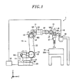
- Fig. 1 is a schematic overall view showing a configuration example of a robot system in accordance with an embodiment.
- Fig. 1 depicts a three-dimensional rectangular coordinate system including a Z-axis whose positive direction extends vertically upward and whose negative direction extends vertically downward, a Y-axis extending in a left-right direction on the drawing sheet surface of Fig. 1 , and an X-axis extending from the rear side of the drawing sheet surface to the front side thereof.
- This rectangular coordinate system may be illustrated in other drawings which are used in the following description.
- a robot system 1 includes a robot 10, a container 30, a workpiece detecting sensor 40 and a processing system 50.
- the robot 10 is an articulated robot having a plurality of links and a plurality of joint parts (first to sixth joint parts) 11 to 16.
- the joint parts interconnect the respective links.
- the links of the robot 10 include a base 20, a swivel part 21, a lower arm 22, an upper arm 23, a first wrist part 24, a second wrist part 25 and a wrist flange 26, all of which are rotatably connected to each other.
- the swivel part 21 is connected to the base 20 so as to rotate about a joint axis J1 of the first joint part 11.
- the lower arm 22 is connected to the swivel part 21 so as to rotate about a joint axis J2 of the second joint part 12 which is perpendicular to the joint axis J1.
- the upper arm 23 is connected to the lower arm 22 so as to rotate about a joint axis J3 of the third joint part 13 which is parallel to the joint axis J2.
- the first wrist part 24 is connected to the upper arm 23 so as to rotate about a joint axis J4 of the fourth joint part 14 which is perpendicular to the joint axis J3.
- the second wrist part 25 is connected to the first wrist part 24 so as to rotate about a joint axis J5 of the fifth joint part 15 which is perpendicular to the joint axis J4.
- the wrist flange 26 is connected to the second wrist part 25 so as to rotate about a joint axis J6 of the sixth joint part 16 which is perpendicular to the joint axis J5.
- perpendicular and parallel do not necessarily require strict accuracy in terms of mathematics but permit a substantial tolerance or error.
- perpendicular means a case where two straight lines (e.g., rotation axes) intersect each other at a right angle in skew position as well as in the same plane.
- the second, the third and the fifth joint part 12, 13 and 15 are joint parts that change the relative positions of the respective links by changing the angles between the respective links connected thereto.
- the fifth joint part 15 changes the relative position of the first wrist part 24 and the second wrist part 25.
- the first, the fourth and the sixth joint part 11, 14 and 16 are joint parts that rotate the driven links about the respective rotation axes without changing the relative positions of the links connected thereto.
- the robot 10 further includes drive sources M1 to M6 that drive the first to sixth joint parts 11 to 16.
- the drive sources M1 to M6 are, e.g., servo motors. While servo motors are taken as examples of the drive sources M1 to M6, the drive sources M1 to M6 are not limited thereto but may be other kinds of motors, e.g., hydraulic motors or the like. In the following description, the drive sources will be referred to as "motors".
- the motor M1 attached to the base 20 drives the first joint part 11 to rotate the swivel part 21.
- the motor M2 attached to the swivel part 21 drives the second joint part 12 to rotate the lower arm 22.
- the motor M3 attached to the lower arm 22 drives the third joint part 13 to rotate the upper arm 23.
- the motor M4 attached to the upper arm 23 drives the fourth joint part 14 to rotate the first wrist part 24.
- the motor M5 attached to the first wrist part 24 drives the fifth joint part 15 to rotate the second wrist part 25.
- the motor M6 attached to the second wrist part 25 drives the sixth joint part 16 to rotate the wrist flange 26.
- encoders E1 to E6 are respectively attached to the first to sixth motors M1 to M6 (see Fig. 3 ). Encoder values indicating the rotation amounts and rotation angles of the respective motors M1 to M6 are outputted from the encoders E1 to E6 to the processing system 50.
- An end effector 27 is mounted to the leading end portion, more precisely the wrist flange 26, of the robot 10.
- the end effector 27 is, e.g., a hand that holds a workpiece W (not shown in Fig. 1 ) to be described later.
- the end effector 27 includes, e.g., a pair of gripping claws 27a and holds (grips) the workpiece W by using the gripping claws 27a. On this point, description will be made later.
- the end effector 27 will be referred to as "hand 27".
- the end effector 27 is not limited to the hand. It is only necessary that the end effector 27 is capable of holding the workpiece W.
- the end effector 27 may be a suction part that sucks and holds the workpiece W.
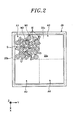
- Fig. 2 is a schematic plane view of a container 30 shown in Fig. 1 .
- the container 30 is a box formed into a substantially parallelepiped shape.
- the upper side of the container 30 in the Z-axis direction is opened and the workpieces W are accommodated within the container 30.
- the container 30 is configured to include a bottom surface 30a having a substantially rectangular shape when seen from the top and a wall portion 30b protruding from the outer edge portion of the bottom surface 30a in the Z-axis positive direction.
- the workpieces W are accommodated in an internal space 30c which is defined by the bottom surface 30a and the wall portion 30b.
- the shape of the container 30 is not limited to the aforementioned shape but may be other shapes, e.g., a polygonal shape, a circular shape, an elliptical shape and the like when seen from the top. Moreover, the container 30 may not include the wall portion 30b.
- the workpieces W are accommodated within the container 30 in bulk.
- the workpieces W are provided only in the left upper section of the container 30 on the drawing sheet surface.
- the workpieces W are also accommodated in bulk in other sections, i.e., in the right upper section and the lower section of the container 30 on the drawing sheet surface.
- Each of the workpieces W includes a ring-shaped portion W1 with a hole and a rod-shaped portion W2 extending radially outward from the outer circumference of the ring-shaped portion W1.
- the hand 27 holds a workpiece W by, e.g., a so-called inside gripping method in which the ring-shaped portion W1 is gripped by inserting the gripping claws 27a in a closed state into the hole of the ring-shaped portion W1 and opening the gripping claws 27a (i.e., moving away the gripping claws 27a from each other).
- the operation of gripping the workpiece W by the hand 27 is performed by the inside gripping method.
- the workpiece W may be held by a so-called outside gripping method in which the workpiece W is gripped by interposing the rod-shaped portion W2 between the gripping claws 27a.
- the workpiece W may be held by properly selecting one of the inside gripping method and the outside gripping method depending on the posture of the workpiece W or the like.
- the portion of the workpiece W gripped by the hand 27 during the workpiece gripping operation is not limited to the aforementioned portions.
- the shape of the workpiece W is not limited to the aforementioned shape but may be other shapes, e.g., a rectangular parallelepiped shape, a spherical shape and the like.
- the workpiece W held in the aforementioned manner is assembled with another kind of workpiece (to be described later) by the robot 10 or another robot (not shown) to thereby manufacture a product.
- the robot 10 or another robot not shown
- the workpieces W are accommodated within the container 30 in bulk as described above, there may be an accommodation state in which no workpiece W can be taken and held by the hand 27 due to the postures and positions of the workpieces W. For example, if a workpiece W interferes with another workpiece W or with the wall portion 30b of the container 30, the workpiece W may not be taken by the hand 27.
- a conventional robot system makes the hand move within the container after the entry of the hand into the container to stir the workpieces and change the postures of the workpieces so as to create another accommodation state in which the workpiece can be held by the hand.
- the stirring operation is performed in such a state, e.g., that the workpieces are crowded within the container, the hand may be caught by the crowded workpieces. If the hand is kept moving in that state, there is a fear that an excessive load is applied from the workpieces to the hand or to the motors and that the hand gets damaged.
- the robot system 1 is configured such that a workpiece stirring operation can be performed without applying an excessive load to the hand 27 and the like and without causing damage to the hand 27.
- a workpiece stirring operation can be performed without applying an excessive load to the hand 27 and the like and without causing damage to the hand 27.
- Detailed description will now be made on the configuration of the robot system 1 for performing such a workpiece stirring operation.
- the workpiece detecting sensor 40 detects the posture and arrangement position of the workpieces W accommodated within the container 30.
- the workpiece detecting sensor 40 is, e.g., a three-dimensional measuring device which is arranged above the container 30 in the Z-axis direction and which can measure the three-dimensional shape of the workpieces W.
- the workpiece detecting sensor 40 it may be possible to use, e.g., a measuring unit that acquires a three-dimensional shape of an object by a scan operation using a laser slit beam.
- Fig. 3 is a block diagram of the robot system 1.
- the processing system 50 includes a computer 60 and a memory 70.
- the computer 60 includes a workpiece detecting sensor controller 61, a sensor information acquirer 62, a workpiece posture/position calculator 63, a determinator 64, a holding operation controller 65, a motion controller 66, a stirring operation controller 67 and a torque limitter 68.
- the memory 70 stores sensor information 71 and workpiece information 72.
- processing system 50 While one processing system 50 is shown in Fig. 3 , it may be possible to provide a plurality of control devices 50 independently and make the control devices communicate to each other.
- the computer 60 controls the overall operation of the processing system 50.
- the workpiece detecting sensor controller 61 outputs, to the workpiece detecting sensor 40, a detection start command, which instructs the workpiece detecting sensor 40 to start detection of the posture and position of the workpieces W, thereby operating the workpiece detecting sensor 40.
- the sensor information acquirer 62 receives detection data from the workpiece detecting sensor 40 and stores the received detection data in the memory 70 as the sensor information 71.
- the sensor information 71 indicates a three-dimensional shape of one or more workpieces W.
- the workpiece posture/position calculator 63 calculates the postures and positions of the workpieces W based on the sensor information 71 and the workpiece information 72.
- the workpiece information 72 defines the three-dimensional shape of the workpieces W or the gripped portion of the workpieces W.
- the ring-shaped portion W1 of the workpiece W is defined as the gripped portion in the case of the inside gripping method
- the rod-shaped portion W2 of the workpiece W is defined as the gripped portion in the case of the outside gripping method.
- the workpiece posture/position calculator 63 calculates the postures and positions of the workpieces W within the container 30 based on the sensor information 71 by performing a matching process through the use of the workpiece information 72.
- the determinator 64 receives the information indicative of the postures and positions of the workpieces W (hereinafter referred to as "workpiece posture information") from the workpiece posture/position calculator 63. Then, based on the received workpiece posture information, the determinator 64 determines whether a workpiece W that can be taken and held by the hand 27 exists among the workpieces W accommodated within the container 30.
- the determinator 64 determines that a holdable workpiece W exists.
- the determinator 64 determines that there is no holdable workpiece W.
- the determinator 64 transmits the determination result indicative of the presence and absence of the holdable workpiece W and the workpiece posture information to the holding operation controller 65 and the stirring operation controller 67. Furthermore, the determinator 64 transmits the determination result to the torque limitter 68.
- the holding operation controller 65 controls the posture of the robot 10 and the operation of the hand 27 to perform a workpiece holding operation.
- the holding operation controller 65 decides a holding posture of the robot 10 capable of performing the holding operation and a start timing at which the hand 27 starts the holding operation.
- the holding posture of the robot 10 means a posture of the robot 10 in which the hand 27 comes closer to a workpiece W that is determined by the determinator 64 to be holdable.
- the motion controller 66 controls the first to sixth motors M1 to M6 based on a signal inputted from the holding operation controller 65 or the like. Encoder values are inputted from the encoders E1 to E6 to the motion controller 66. In Fig. 3 , for the sake of simplicity in illustration, the first to sixth motors M1 to M6 are illustrated in a single block. However, the motion controller 66 individually controls the first to sixth motors M1 to M6.
- the motion controller 66 controls the positions of the first to sixth motors M1 to M6 based on the inputted signal and the encoder values, so that the robot 10 can take the holding position.
- the hand 27 is positioned near the workpiece W to be held.
- the holding operation controller 65 drives the hand 27 at the aforementioned start timing to hold (grip) the workpiece W. In this way, the holding operation controller 65 allows the hand 27 to perform the workpiece holding operation, while controlling the posture of the robot 10 through the motion controller 66.
- the stirring operation controller 67 controls the robot 10 to perform a stirring operation for the workpieces W.
- the stirring operation controller 67 decides a start position of the stirring operation of the hand 27 within the container 30 based on the posture of the workpieces W of the container 30.
- the start position of the stirring operation means, e.g., a location within the container 30 having a space into which the hand 27 can enter as indicated by a symbol S in Fig. 2 , i.e., a position from which the stirring operation is started.
- the stirring operation controller 67 generates a movement instruction to move the hand 27 for a predetermined distance from the start position S in a predetermined direction (e.g., toward the center of a region to be described later (in the example shown in Fig. 2 , the Y-axis positive direction from the start position S)).
- a signal indicative of the start position S of the stirring operation and the movement instruction is inputted to the motion controller 66.
- the motion controller 66 controls the motions of the first to sixth motors M1 to M6 such that the hand 27 is positioned in the start position S inputted from the stirring operation controller 67. Thus, the hand 27 is positioned in the start position S.
- the torque limitter 68 receives the determination result from the determinator 64.
- the torque limitter 68 limits the motion torques of the first to sixth motors M1 to M6 to be commanded from the motion controller 66 to the first to sixth motors M1 to M6.
- the motion controller 66 controls the powers (torques) of the first to sixth motors M1 to M6.
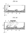
- Fig. 4A is an explanatory view illustrating a state in which the hand 27 is positioned in the start position S of the stirring operation.
- Fig. 4B is an explanatory view illustrating a state in which the hand 27 shown in Fig. 4A is moved for a predetermined distance from the start position S.
- the hand 27, the workpieces W and the container 30 are schematically shown with the illustration of the wrist flange 26 omitted.
- the motion controller 66 controls the motions of the first to sixth motors M1 to M6 such that the hand 27 is positioned in the start position S of the stirring operation.
- the hand 27 is positioned in the start position S in such a state that the base end portion of the hand 27 is inclined toward the center of the container 30 with respect to the wall portion 30b. This makes it possible to prevent the hand 27 from interfering with the wall portion 30b of the container 30.
- the motion controller 66 controls the motions of the first to sixth motors M1 to M6 so that the hand 27 can move a predetermined distance from the start position S in a specified direction (the Y-axis positive direction in this example) within the container 30.
- the motion controller 66 controls the power of the first to sixth motors M1 to M6 in a state in which the motion torques of the first to sixth motors M1 to M6 are limited by the torque limitter 68, e.g., in a state in which the upper limit values of the motion torques are set by the torque limitter 68.
- the hand 27 may be caught by the workpiece Wa during the movement of the hand 27 as indicated by a double-dot chain line. Since the powers of the first to sixth motors M1 to M6 are controlled in the aforementioned manner, the hand 27 is inclined due to the external force exerted by the workpiece Wa as indicated by a solid line. Even if the hand 27 is moved as indicated by a broken line, the hand 27 is moved to follow the outlines of the workpieces W.
- the aforementioned configuration makes it possible to continue the stirring operation of the workpieces W without applying an excessive load from the workpiece Wa to the hand 27 and the respective motors M1 to M6 and without causing damage to the hand 27.
- the hand 27 is positioned in the start position S and is then moved for a predetermined distance within the container 30 to perform the stirring operation. It is therefore possible to efficiently mix the workpieces W within the container 30.
- the torque limitter 68 is configured to limit all the motion torques of the first to sixth motors M1 to M6.
- the present disclosure is not limited thereto.
- the torque limitter 68 may be configured to limit at least the motion torque of the fifth motor M5 which is arranged in a position nearest to the hand 27 and which drives the fifth joint part 15 that changes the relative positions of the links connected thereto.
- the reason for limiting the motion torque of the fifth motor M5 in the aforementioned manner is that, when the hand 27 is caught by the workpiece W during the stirring operation, the fifth joint part 15 is relatively easily affected by the external force originating from the workpiece W.
- the torque limitter 68 may be configured to limit the motion torques of at least two motors among the first to sixth motors M1 to M6.
- the torque limitter 68 may be configured to limit the motion torques of at least two motors among the first to sixth motors M1 to M6.
- the upper limit values of the motion torques of the first to sixth motors M1 to M6, which are limited by the torque limitter 68, may be set different from one another in the first to sixth motors M1 to M6.
- the upper limit value of the motion torque of the fifth motor M5 that drives the joint part relatively easily affected by the external force when the hand 27 is caught by the workpiece W may be set to be the lowest
- the upper limit value of the motion torque of the fourth motor M4 may be set to be the second lowest (i.e., the upper limit value of the motion torque of the fifth motor M5 is set smaller than that of the fourth motor M4). This makes it possible to effectively prevent an excessive load from being applied to the fourth and the fifth motor M4 and M5.
- the container 30 is divided into a plurality of regions and the holding operation and the stirring operation are performed in each of the regions of the container 30.
- the bottom surface 30a of the container 30 is divided into a plurality of (e.g., four) regions A1 to A4 so that the holding operation controller 65 can identify the regions A1 to A4.
- the holding operation controller 65 allows the motion controller 66 to perform the holding operation for the workpiece W within one specified region (e.g., the region A1) among the regions A1 to A4.
- the stirring operation controller 67 allows the motion controller 66 to perform the stirring operation.
- the holding operation controller 65 allows the hand 27 to move to another region (e.g., the region A2) different from the specified region (the region A1 in this example) and allows the motion controller 66 to perform the holding operation.
- the hand 27 is moved to another region and is allowed to perform the holding operation. Accordingly, the holding operation or the stirring operation can be efficiently performed within the container 30 without repeating the stirring operation for a long period of time.
- the bottom surface 30a of the container 30 is divided into four regions A1 to A4, but the present disclosure is not limited thereto.
- the bottom surface 30a of the container 30 may be divided into three or less regions, or five or more regions.
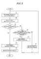
- FIG. 5 is a flowchart showing a processing procedure performed by the robot system 1 in accordance with the embodiment.
- the workpiece detecting sensor controller 61 outputs a detection start instruction to the workpiece detecting sensor 40 to operate the workpiece detecting sensor 40 (step S1). Then, the workpiece posture/position calculator 63 calculates a workpiece posture based on the sensor information 71 and the workpiece information 72 stored in the memory 70 (step S2).
- the determinator 64 determines whether a workpiece W capable of being held by the hand 27 exists among the workpieces W within the container 30 (step S3). If a holdable workpiece W exists (if Yes in step S3), the holding operation controller 65 allows the robot 10 to perform a holding operation (step S4).
- Fig. 6 is a schematic side view showing the product B. While an assembled member has been illustrated as the product B, this is nothing more than one example and is not limitative.
- the holding operation controller 65 determines whether the number of the stirring operation performed has reached a predetermined number, i.e., whether the number of the stirring operation performed is equal to or greater than the predetermined number (step S6).
- step S6 If the number of the stirring operation performed has not reached the predetermined number (if No in step S6), the stirring operation controller 67 allows the robot 10 to perform the stirring operation (step S7). On the other hand, if the number of the stirring operation performed has reached the predetermined number (if Yes in step S6), the holding operation controller 65 allows the hand 27 to move to another region different from the specified region where the holding operation and the stirring operation has been performed (step S8). Then, step S1 is performed again.
- the robot system in accordance with the present embodiment includes the robot 10, the container 30, the determinator 64, the motion controller 66, the torque limitter 68 and the stirring operation controller 67.
- the robot 10 includes the first to sixth motors M1 to M6 for driving the first to sixth joint parts 11 to 16, respectively, and the hand 27 for holding the workpiece W.
- the workpieces W are accommodated within the container 30.
- the determinator 64 determines whether a workpiece W capable of being held by the hand 27 exists among the workpieces W of the container 30.
- the motion controller 66 controls the motions of the first to sixth motors M1 to M6.
- the torque limitter 68 limits the motion torques to be commanded from the motion controller 66 to the first to sixth motors M1 to M6.
- the stirring operation controller 67 allows the motion controller 66 to perform a stirring operation by which the workpieces W accommodated within the container 30 are stirred by the hand 27 with the motion torques limited by the torque limitter 68. This makes it possible to perform the stirring operation for the workpieces W without applying an excessive load to the hand 27 and the like and without causing damage to the hand 27.
- the six-axis robot has been described as one example of the robot 10.
- the present disclosure is not limited to the six-axis robot. It may be possible to use, in addition to the six-axis robot, e.g., a seven-axis robot or an eight-axis robot. It may also be possible to use other kinds of robots such as a dual-arm robot and the like.
Landscapes
- Engineering & Computer Science (AREA)
- Robotics (AREA)
- Mechanical Engineering (AREA)
- Human Computer Interaction (AREA)
- Manipulator (AREA)
Abstract
Description
- Embodiments disclosed herein relate to a robot system and a product manufacturing method.
- Japanese Patent Application Publication No.
2011-115930 - In the above robot system, workpieces are accommodated within a container in bulk so as to overlap with one another, for example. For that reason, there may be an accommodation state in which the workpieces interfere with one another or with the container due to the postures and positions of the workpieces, which makes it impossible for the end effector to hold the workpieces.
- In the case of this accommodation state, the aforementioned robot system allows the end effector to move in the container after the entry of the end effector into the container to stir the workpieces and change the postures of the workpieces so as to create another accommodation state in which the workpieces can be held by the end effector.
- However, if the stirring operation is performed in such a state that the workpieces are crowded within the container, the end effector may be caught by the workpieces. In the robot system configured as above, the end effector is moved in the caught state. If the end effector is continuously moved in that state, there is a fear that an excessive load is applied from the workpieces to the end effector or a drive motor and further that the end effector gets damaged.
- In view of the above, the embodiments provide a robot system and a product manufacturing method which are capable of performing a workpiece stirring operation without applying an excessive load to an end effector or the like, and without causing damage to the end effector.
- In accordance with an aspect of the embodiment, a robot system includes a robot, a container, a determinator, a motion controller, a torque limitter and a stirring operation controller. The robot includes at least one joint part, at least one drive source for driving the at least one joint part and an end effector for holding a workpiece. The workpieces are accommodated within the container. The determinator is configured to determine whether a workpiece capable of being held by the end effector exists among the workpieces accommodated within the container. The motion controller is configured to control a motion of each drive source of the robot. The torque limitter is configured to, when the determinator determines that there is no workpiece capable of being held by the end effector, limit a motion torque of at least one of the each drive source to be commanded from the motion controller to the each drive source. The stirring operation controller is configured to, when the determinator determines that there is no workpiece capable of being held by the end effector, allow the motion controller to perform a stirring operation, by which the workpieces accommodated within the container are stirred by the end effector, in a state where the motion torque is limited by the torque limitter.
- In accordance with the aspect of the embodiment, it is possible to perform a workpiece stirring operation without applying an excessive load to an end effector or the like, and without causing damage to the end effector.
-
-
Fig. 1 is a schematic overall view showing a configuration example of a robot system in accordance with an embodiment. -
Fig. 2 is a schematic plane view of a container shown inFig. 1 . -
Fig. 3 is a block diagram of the robot system shown inFig. 1 . -
Fig. 4A is an explanatory view illustrating a state in which a hand is positioned in a start position of a stirring operation. -
Fig. 4B is an explanatory view illustrating a state in which the hand shown inFig. 4A is moved for a predetermined distance from the start position. -
Fig. 5 is a flowchart showing a processing procedure performed by the robot system in accordance with an embodiment. -
Fig. 6 is a schematic side view showing a product. - Hereinafter, embodiments of a robot system and a product manufacturing method will now be described in detail with reference to the accompanying drawings. The present disclosure is not limited to the embodiments to be described below.
-
Fig. 1 is a schematic overall view showing a configuration example of a robot system in accordance with an embodiment. For the sake of easy understanding,Fig. 1 depicts a three-dimensional rectangular coordinate system including a Z-axis whose positive direction extends vertically upward and whose negative direction extends vertically downward, a Y-axis extending in a left-right direction on the drawing sheet surface ofFig. 1 , and an X-axis extending from the rear side of the drawing sheet surface to the front side thereof. This rectangular coordinate system may be illustrated in other drawings which are used in the following description. - Hereinafter, description may be made using such expressions as "X-axis direction", "Y-axis direction" and "Z-axis direction", which merely denote respective directions with respect to the posture of the robot shown in
Fig. 1 , and the present disclosure is not limited to the expressed directions. - As shown in
Fig. 1 , arobot system 1 includes arobot 10, acontainer 30, aworkpiece detecting sensor 40 and aprocessing system 50. - The
robot 10 is an articulated robot having a plurality of links and a plurality of joint parts (first to sixth joint parts) 11 to 16. The joint parts interconnect the respective links. The links of therobot 10 include abase 20, aswivel part 21, alower arm 22, anupper arm 23, afirst wrist part 24, asecond wrist part 25 and awrist flange 26, all of which are rotatably connected to each other. - Specifically, the
swivel part 21 is connected to thebase 20 so as to rotate about a joint axis J1 of the firstjoint part 11. Thelower arm 22 is connected to theswivel part 21 so as to rotate about a joint axis J2 of the secondjoint part 12 which is perpendicular to the joint axis J1. Theupper arm 23 is connected to thelower arm 22 so as to rotate about a joint axis J3 of the thirdjoint part 13 which is parallel to the joint axis J2. Thefirst wrist part 24 is connected to theupper arm 23 so as to rotate about a joint axis J4 of the fourthjoint part 14 which is perpendicular to the joint axis J3. - The
second wrist part 25 is connected to thefirst wrist part 24 so as to rotate about a joint axis J5 of the fifthjoint part 15 which is perpendicular to the joint axis J4. Thewrist flange 26 is connected to thesecond wrist part 25 so as to rotate about a joint axis J6 of the sixthjoint part 16 which is perpendicular to the joint axis J5. - The terms "perpendicular" and "parallel" do not necessarily require strict accuracy in terms of mathematics but permit a substantial tolerance or error. In the subject specification, the term "perpendicular" means a case where two straight lines (e.g., rotation axes) intersect each other at a right angle in skew position as well as in the same plane.
- Among the first to sixth
joint parts 11 to 16, the second, the third and the fifthjoint part joint part 15 changes the relative position of thefirst wrist part 24 and thesecond wrist part 25. The first, the fourth and the sixthjoint part - The
robot 10 further includes drive sources M1 to M6 that drive the first to sixthjoint parts 11 to 16. The drive sources M1 to M6 are, e.g., servo motors. While servo motors are taken as examples of the drive sources M1 to M6, the drive sources M1 to M6 are not limited thereto but may be other kinds of motors, e.g., hydraulic motors or the like. In the following description, the drive sources will be referred to as "motors". - Description will now be made on the respective motors M1 to M6. The motor M1 attached to the
base 20 drives the firstjoint part 11 to rotate theswivel part 21. The motor M2 attached to theswivel part 21 drives the secondjoint part 12 to rotate thelower arm 22. The motor M3 attached to thelower arm 22 drives the thirdjoint part 13 to rotate theupper arm 23. - The motor M4 attached to the
upper arm 23 drives the fourthjoint part 14 to rotate thefirst wrist part 24. The motor M5 attached to thefirst wrist part 24 drives the fifthjoint part 15 to rotate thesecond wrist part 25. The motor M6 attached to thesecond wrist part 25 drives the sixthjoint part 16 to rotate thewrist flange 26. - While not shown in
Fig. 1 , encoders E1 to E6 are respectively attached to the first to sixth motors M1 to M6 (seeFig. 3 ). Encoder values indicating the rotation amounts and rotation angles of the respective motors M1 to M6 are outputted from the encoders E1 to E6 to theprocessing system 50. - An
end effector 27 is mounted to the leading end portion, more precisely thewrist flange 26, of therobot 10. Theend effector 27 is, e.g., a hand that holds a workpiece W (not shown inFig. 1 ) to be described later. Theend effector 27 includes, e.g., a pair ofgripping claws 27a and holds (grips) the workpiece W by using thegripping claws 27a. On this point, description will be made later. - In the following description, the
end effector 27 will be referred to as "hand 27". However, theend effector 27 is not limited to the hand. It is only necessary that theend effector 27 is capable of holding the workpiece W. For example, theend effector 27 may be a suction part that sucks and holds the workpiece W. -
Fig. 2 is a schematic plane view of acontainer 30 shown inFig. 1 . Thecontainer 30 is a box formed into a substantially parallelepiped shape. The upper side of thecontainer 30 in the Z-axis direction is opened and the workpieces W are accommodated within thecontainer 30. In other words, thecontainer 30 is configured to include abottom surface 30a having a substantially rectangular shape when seen from the top and awall portion 30b protruding from the outer edge portion of thebottom surface 30a in the Z-axis positive direction. The workpieces W are accommodated in aninternal space 30c which is defined by thebottom surface 30a and thewall portion 30b. - The shape of the
container 30 is not limited to the aforementioned shape but may be other shapes, e.g., a polygonal shape, a circular shape, an elliptical shape and the like when seen from the top. Moreover, thecontainer 30 may not include thewall portion 30b. - As shown in
Fig. 2 , the workpieces W are accommodated within thecontainer 30 in bulk. InFig. 2 , for the sake of simplicity in illustration, the workpieces W are provided only in the left upper section of thecontainer 30 on the drawing sheet surface. However, the workpieces W are also accommodated in bulk in other sections, i.e., in the right upper section and the lower section of thecontainer 30 on the drawing sheet surface. - Each of the workpieces W includes a ring-shaped portion W1 with a hole and a rod-shaped portion W2 extending radially outward from the outer circumference of the ring-shaped portion W1. The
hand 27 holds a workpiece W by, e.g., a so-called inside gripping method in which the ring-shaped portion W1 is gripped by inserting thegripping claws 27a in a closed state into the hole of the ring-shaped portion W1 and opening thegripping claws 27a (i.e., moving away thegripping claws 27a from each other). - In the foregoing description, the operation of gripping the workpiece W by the
hand 27 is performed by the inside gripping method. However, the present disclosure is not limited thereto. For example, the workpiece W may be held by a so-called outside gripping method in which the workpiece W is gripped by interposing the rod-shaped portion W2 between thegripping claws 27a. In addition, the workpiece W may be held by properly selecting one of the inside gripping method and the outside gripping method depending on the posture of the workpiece W or the like. Further, the portion of the workpiece W gripped by thehand 27 during the workpiece gripping operation is not limited to the aforementioned portions. Furthermore, the shape of the workpiece W is not limited to the aforementioned shape but may be other shapes, e.g., a rectangular parallelepiped shape, a spherical shape and the like. - The workpiece W held in the aforementioned manner is assembled with another kind of workpiece (to be described later) by the
robot 10 or another robot (not shown) to thereby manufacture a product. In this regard, description will be made later. - Since the workpieces W are accommodated within the
container 30 in bulk as described above, there may be an accommodation state in which no workpiece W can be taken and held by thehand 27 due to the postures and positions of the workpieces W. For example, if a workpiece W interferes with another workpiece W or with thewall portion 30b of thecontainer 30, the workpiece W may not be taken by thehand 27. - In the case of this accommodation state, a conventional robot system makes the hand move within the container after the entry of the hand into the container to stir the workpieces and change the postures of the workpieces so as to create another accommodation state in which the workpiece can be held by the hand.
- However, when the stirring operation is performed in such a state, e.g., that the workpieces are crowded within the container, the hand may be caught by the crowded workpieces. If the hand is kept moving in that state, there is a fear that an excessive load is applied from the workpieces to the hand or to the motors and that the hand gets damaged.
- For that reason, the
robot system 1 according to the present disclosure is configured such that a workpiece stirring operation can be performed without applying an excessive load to thehand 27 and the like and without causing damage to thehand 27. Detailed description will now be made on the configuration of therobot system 1 for performing such a workpiece stirring operation. - Referring back to
Fig. 1 , theworkpiece detecting sensor 40 detects the posture and arrangement position of the workpieces W accommodated within thecontainer 30. Specifically, theworkpiece detecting sensor 40 is, e.g., a three-dimensional measuring device which is arranged above thecontainer 30 in the Z-axis direction and which can measure the three-dimensional shape of the workpieces W. As theworkpiece detecting sensor 40, it may be possible to use, e.g., a measuring unit that acquires a three-dimensional shape of an object by a scan operation using a laser slit beam. - The
processing system 50 controls the operations of the respective motors M1 to M6 and thehand 27 of therobot 10 and the operation of theworkpiece detecting sensor 40.Fig. 3 is a block diagram of therobot system 1. - As shown in
Fig. 3 , theprocessing system 50 includes acomputer 60 and amemory 70. Thecomputer 60 includes a workpiece detectingsensor controller 61, asensor information acquirer 62, a workpiece posture/position calculator 63, adeterminator 64, a holdingoperation controller 65, amotion controller 66, a stirringoperation controller 67 and atorque limitter 68. Thememory 70stores sensor information 71 andworkpiece information 72. - While one
processing system 50 is shown inFig. 3 , it may be possible to provide a plurality ofcontrol devices 50 independently and make the control devices communicate to each other. - The
computer 60 controls the overall operation of theprocessing system 50. The workpiece detectingsensor controller 61 outputs, to theworkpiece detecting sensor 40, a detection start command, which instructs theworkpiece detecting sensor 40 to start detection of the posture and position of the workpieces W, thereby operating theworkpiece detecting sensor 40. - The
sensor information acquirer 62 receives detection data from theworkpiece detecting sensor 40 and stores the received detection data in thememory 70 as thesensor information 71. Here, thesensor information 71 indicates a three-dimensional shape of one or more workpieces W. - The workpiece posture/
position calculator 63 calculates the postures and positions of the workpieces W based on thesensor information 71 and theworkpiece information 72. Here, theworkpiece information 72 defines the three-dimensional shape of the workpieces W or the gripped portion of the workpieces W. Specifically, for example, the ring-shaped portion W1 of the workpiece W is defined as the gripped portion in the case of the inside gripping method, and the rod-shaped portion W2 of the workpiece W is defined as the gripped portion in the case of the outside gripping method. - The workpiece posture/
position calculator 63 calculates the postures and positions of the workpieces W within thecontainer 30 based on thesensor information 71 by performing a matching process through the use of theworkpiece information 72. - The
determinator 64 receives the information indicative of the postures and positions of the workpieces W (hereinafter referred to as "workpiece posture information") from the workpiece posture/position calculator 63. Then, based on the received workpiece posture information, thedeterminator 64 determines whether a workpiece W that can be taken and held by thehand 27 exists among the workpieces W accommodated within thecontainer 30. - Specifically, for example, if a workpiece W within the
container 30 is in a state that can be taken and held by thehand 27, thedeterminator 64 determines that a holdable workpiece W exists. On the other hand, if no workpiece W within thecontainer 30 is in a state that can be taken and held by thehand 27 due to, e.g., the mutual overlap of the workpieces W, thedeterminator 64 determines that there is no holdable workpiece W. - The
determinator 64 transmits the determination result indicative of the presence and absence of the holdable workpiece W and the workpiece posture information to theholding operation controller 65 and the stirringoperation controller 67. Furthermore, thedeterminator 64 transmits the determination result to thetorque limitter 68. - Based on the determination result and the workpiece posture information transmitted from the
determinator 64, the holdingoperation controller 65 controls the posture of therobot 10 and the operation of thehand 27 to perform a workpiece holding operation. - Specifically, in the case where the
determinator 64 determines that there is a workpiece W capable of being taken and held by thehand 27, the holdingoperation controller 65 decides a holding posture of therobot 10 capable of performing the holding operation and a start timing at which thehand 27 starts the holding operation. Here, the holding posture of therobot 10 means a posture of therobot 10 in which thehand 27 comes closer to a workpiece W that is determined by thedeterminator 64 to be holdable. - The
motion controller 66 controls the first to sixth motors M1 to M6 based on a signal inputted from the holdingoperation controller 65 or the like. Encoder values are inputted from the encoders E1 to E6 to themotion controller 66. InFig. 3 , for the sake of simplicity in illustration, the first to sixth motors M1 to M6 are illustrated in a single block. However, themotion controller 66 individually controls the first to sixth motors M1 to M6. - When a signal indicative of the holding posture of the
robot 10 is inputted from the holdingoperation controller 65 to themotion controller 66, themotion controller 66 controls the positions of the first to sixth motors M1 to M6 based on the inputted signal and the encoder values, so that therobot 10 can take the holding position. Thus, thehand 27 is positioned near the workpiece W to be held. - Thereafter, the holding
operation controller 65 drives thehand 27 at the aforementioned start timing to hold (grip) the workpiece W. In this way, the holdingoperation controller 65 allows thehand 27 to perform the workpiece holding operation, while controlling the posture of therobot 10 through themotion controller 66. - Based on the determination result and the workpiece posture information transmitted from the
determinator 64, the stirringoperation controller 67 controls therobot 10 to perform a stirring operation for the workpieces W. - Specifically, when the
determinator 64 determines that there is no workpiece W capable of being held by thehand 27, the stirringoperation controller 67 decides a start position of the stirring operation of thehand 27 within thecontainer 30 based on the posture of the workpieces W of thecontainer 30. Here, the start position of the stirring operation means, e.g., a location within thecontainer 30 having a space into which thehand 27 can enter as indicated by a symbol S inFig. 2 , i.e., a position from which the stirring operation is started. - The stirring
operation controller 67 generates a movement instruction to move thehand 27 for a predetermined distance from the start position S in a predetermined direction (e.g., toward the center of a region to be described later (in the example shown inFig. 2 , the Y-axis positive direction from the start position S)). A signal indicative of the start position S of the stirring operation and the movement instruction is inputted to themotion controller 66. - The
motion controller 66 controls the motions of the first to sixth motors M1 to M6 such that thehand 27 is positioned in the start position S inputted from the stirringoperation controller 67. Thus, thehand 27 is positioned in the start position S. - Description will now be made on the
torque limitter 68. As mentioned above, thetorque limitter 68 receives the determination result from thedeterminator 64. When thedeterminator 64 determines that there is no workpiece W capable of being held by thehand 27, thetorque limitter 68 limits the motion torques of the first to sixth motors M1 to M6 to be commanded from themotion controller 66 to the first to sixth motors M1 to M6. - In this way, when the stirring operation is performed due to the absence of a holdable workpiece W, the motion torques of the first to sixth motors M1 to M6 are limited by the
torque limitter 68. That is to say, themotion controller 66 controls the powers (torques) of the first to sixth motors M1 to M6. - The stirring operation implemented by the
motion controller 66 will now be described in detail with reference toFigs. 4A and 4B. Fig. 4A is an explanatory view illustrating a state in which thehand 27 is positioned in the start position S of the stirring operation.Fig. 4B is an explanatory view illustrating a state in which thehand 27 shown inFig. 4A is moved for a predetermined distance from the start position S. InFigs. 4A and 4B , for the sake of simplicity in illustration, thehand 27, the workpieces W and thecontainer 30 are schematically shown with the illustration of thewrist flange 26 omitted. - First, as shown in
Fig. 4A , themotion controller 66 controls the motions of the first to sixth motors M1 to M6 such that thehand 27 is positioned in the start position S of the stirring operation. At this time, for example, thehand 27 is positioned in the start position S in such a state that the base end portion of thehand 27 is inclined toward the center of thecontainer 30 with respect to thewall portion 30b. This makes it possible to prevent thehand 27 from interfering with thewall portion 30b of thecontainer 30. - Next, based on the aforementioned movement instruction, the
motion controller 66 controls the motions of the first to sixth motors M1 to M6 so that thehand 27 can move a predetermined distance from the start position S in a specified direction (the Y-axis positive direction in this example) within thecontainer 30. At this time, themotion controller 66 controls the power of the first to sixth motors M1 to M6 in a state in which the motion torques of the first to sixth motors M1 to M6 are limited by thetorque limitter 68, e.g., in a state in which the upper limit values of the motion torques are set by thetorque limitter 68. - Accordingly, for example, if the workpieces W are crowded as shown in
Fig. 4B , thehand 27 may be caught by the workpiece Wa during the movement of thehand 27 as indicated by a double-dot chain line. Since the powers of the first to sixth motors M1 to M6 are controlled in the aforementioned manner, thehand 27 is inclined due to the external force exerted by the workpiece Wa as indicated by a solid line. Even if thehand 27 is moved as indicated by a broken line, thehand 27 is moved to follow the outlines of the workpieces W. - Even if the
hand 27 is caught by the workpiece Wa, the aforementioned configuration makes it possible to continue the stirring operation of the workpieces W without applying an excessive load from the workpiece Wa to thehand 27 and the respective motors M1 to M6 and without causing damage to thehand 27. - By continuing the stirring operation of the workpieces W, it is possible to increase the number of the workpieces W whose postures are changed by the stirring operation. Accordingly, there may be an instance where the
hand 27 previously caught by the workpiece Wa collides with another workpiece Wb, as indicated by a single-dot chain line inFig. 4B , and changes the posture of the workpiece Wb to a posture in which the workpiece Wb can be taken and held by thehand 27. - As described above, the
hand 27 is positioned in the start position S and is then moved for a predetermined distance within thecontainer 30 to perform the stirring operation. It is therefore possible to efficiently mix the workpieces W within thecontainer 30. - In the foregoing description, the
torque limitter 68 is configured to limit all the motion torques of the first to sixth motors M1 to M6. However, the present disclosure is not limited thereto. For example, thetorque limitter 68 may be configured to limit at least the motion torque of the fifth motor M5 which is arranged in a position nearest to thehand 27 and which drives the fifthjoint part 15 that changes the relative positions of the links connected thereto. - The reason for limiting the motion torque of the fifth motor M5 in the aforementioned manner is that, when the
hand 27 is caught by the workpiece W during the stirring operation, the fifthjoint part 15 is relatively easily affected by the external force originating from the workpiece W. By limiting at least the motion torque of the fifth motor M5 that drives the fifthjoint part 15, it is possible to restrain an excessive load from being applied to the fifth motor M5 and the entirety of therobot 10. - The torque limitter 68 may be configured to limit the motion torques of at least two motors among the first to sixth motors M1 to M6. In the case of limiting the motion torques of two motors, if the
hand 27 is caught by the workpiece W as mentioned above, it is preferable to limit the motion torques of, e.g., the fourth and the fifth motor M4 and M5 that drive the fourth and the fifthjoint part - The upper limit values of the motion torques of the first to sixth motors M1 to M6, which are limited by the
torque limitter 68, may be set different from one another in the first to sixth motors M1 to M6. For example, the upper limit value of the motion torque of the fifth motor M5 that drives the joint part relatively easily affected by the external force when thehand 27 is caught by the workpiece W may be set to be the lowest, and the upper limit value of the motion torque of the fourth motor M4 may be set to be the second lowest (i.e., the upper limit value of the motion torque of the fifth motor M5 is set smaller than that of the fourth motor M4). This makes it possible to effectively prevent an excessive load from being applied to the fourth and the fifth motor M4 and M5. - Next, description will be made on a location within the
container 30 where the holding operation and the stirring operation are performed. Specifically, thecontainer 30 is divided into a plurality of regions and the holding operation and the stirring operation are performed in each of the regions of thecontainer 30. In more detail, as indicated by the broken line inFig. 2 , thebottom surface 30a of thecontainer 30 is divided into a plurality of (e.g., four) regions A1 to A4 so that the holdingoperation controller 65 can identify the regions A1 to A4. - The holding
operation controller 65 allows themotion controller 66 to perform the holding operation for the workpiece W within one specified region (e.g., the region A1) among the regions A1 to A4. When it is determined that there is no workpiece W capable of being held by thehand 27 in the specified region (the region A1 in this example), the stirringoperation controller 67 allows themotion controller 66 to perform the stirring operation. - When the number of the stirring operation performed by the stirring
operation controller 67 reaches a predetermined number, the holdingoperation controller 65 allows thehand 27 to move to another region (e.g., the region A2) different from the specified region (the region A1 in this example) and allows themotion controller 66 to perform the holding operation. - That is to say, if a holdable workpiece W does not exist despite the repeated stirring operations, the
hand 27 is moved to another region and is allowed to perform the holding operation. Accordingly, the holding operation or the stirring operation can be efficiently performed within thecontainer 30 without repeating the stirring operation for a long period of time. - In the foregoing description, the
bottom surface 30a of thecontainer 30 is divided into four regions A1 to A4, but the present disclosure is not limited thereto. Thebottom surface 30a of thecontainer 30 may be divided into three or less regions, or five or more regions. - Next, a processing procedure performed by the
robot system 1 in accordance with the embodiment will be described with reference toFig. 5. Fig. 5 is a flowchart showing a processing procedure performed by therobot system 1 in accordance with the embodiment. - As shown in
Fig. 5 , the workpiece detectingsensor controller 61 outputs a detection start instruction to theworkpiece detecting sensor 40 to operate the workpiece detecting sensor 40 (step S1). Then, the workpiece posture/position calculator 63 calculates a workpiece posture based on thesensor information 71 and theworkpiece information 72 stored in the memory 70 (step S2). - Next, based on the workpiece posture thus calculated, the
determinator 64 determines whether a workpiece W capable of being held by thehand 27 exists among the workpieces W within the container 30 (step S3). If a holdable workpiece W exists (if Yes in step S3), the holdingoperation controller 65 allows therobot 10 to perform a holding operation (step S4). - Subsequently, the workpiece W and another workpiece Wc are assembled together by the
robot 10 or another robot (not shown), thereby manufacturing a product B as shown inFig. 6 (step S5).Fig. 6 is a schematic side view showing the product B. While an assembled member has been illustrated as the product B, this is nothing more than one example and is not limitative. - On the other hand, if there is no holdable workpiece W (if No in step S3), the holding
operation controller 65 determines whether the number of the stirring operation performed has reached a predetermined number, i.e., whether the number of the stirring operation performed is equal to or greater than the predetermined number (step S6). - If the number of the stirring operation performed has not reached the predetermined number (if No in step S6), the stirring
operation controller 67 allows therobot 10 to perform the stirring operation (step S7). On the other hand, if the number of the stirring operation performed has reached the predetermined number (if Yes in step S6), the holdingoperation controller 65 allows thehand 27 to move to another region different from the specified region where the holding operation and the stirring operation has been performed (step S8). Then, step S1 is performed again. - As described above, the robot system in accordance with the present embodiment includes the
robot 10, thecontainer 30, thedeterminator 64, themotion controller 66, thetorque limitter 68 and the stirringoperation controller 67. - The
robot 10 includes the first to sixth motors M1 to M6 for driving the first to sixthjoint parts 11 to 16, respectively, and thehand 27 for holding the workpiece W. The workpieces W are accommodated within thecontainer 30. Thedeterminator 64 determines whether a workpiece W capable of being held by thehand 27 exists among the workpieces W of thecontainer 30. Themotion controller 66 controls the motions of the first to sixth motors M1 to M6. When thedeterminator 64 determines that there is no workpiece W capable of being held by thehand 27, thetorque limitter 68 limits the motion torques to be commanded from themotion controller 66 to the first to sixth motors M1 to M6. The stirringoperation controller 67 allows themotion controller 66 to perform a stirring operation by which the workpieces W accommodated within thecontainer 30 are stirred by thehand 27 with the motion torques limited by thetorque limitter 68. This makes it possible to perform the stirring operation for the workpieces W without applying an excessive load to thehand 27 and the like and without causing damage to thehand 27. - In the aforementioned embodiment, the six-axis robot has been described as one example of the
robot 10. However, the present disclosure is not limited to the six-axis robot. It may be possible to use, in addition to the six-axis robot, e.g., a seven-axis robot or an eight-axis robot. It may also be possible to use other kinds of robots such as a dual-arm robot and the like. - It should be understood by those skilled in the art that various modifications, combinations, sub-combinations and alterations may occur depending on design requirements and other factors insofar as they are within the scope of the appended claims or the equivalents thereof.
Claims (6)
- A robot system comprising:a robot including at least one joint part, at least one drive source for driving the at least one joint part and an end effector;a container configured to accommodate workpieces;a determinator configured to determine whether a workpiece capable of being held by the end effector exists among the workpieces accommodated within the container;a motion controller configured to control a motion of each drive source of the robot;a torque limitter configured to, when the determinator determines that there is no workpiece capable of being held by the end effector, limit a motion torque of at least one of the each drive source to be commanded from the motion controller to the each drive source; anda stirring operation controller configured to, when the determinator determines that there is no workpiece capable of being held by the end effector, allow the motion controller to perform a stirring operation, by which the workpieces accommodated within the container are stirred by the end effector, in a state where the motion torque is limited by the torque limitter.
- The system of claim 1, wherein the at least one joint part includes a joint part which is arranged in a position nearest to the end effector and configured to change relative positions of links connected to the joint part, the at least one drive source includes a drive source for driving the joint part arranged in a position nearest to the end effector, and the torque limitter limits a motion torque of the drive source.
- The system of claim 1, wherein the at least one joint part includes a plurality of joint parts, the at least one drive source includes a plurality of drive sources for driving the respective joint parts, and the torque limitter limits motion torques of at least two of the plurality of drive sources.
- The system of any one of claims 1 to 3, wherein the stirring operation controller determines a start position of the stirring operation of the end effector within the container, based on postures of the workpieces, and allows the motion controller to place the end effector at the start position and to move the end effector for a predetermined distance within the container such that the stirring operation is performed.
- The system of any one of claims 1 to 4, further comprising:a holding operation controller configured to allow the motion controller to perform a holding operation, by which one of the workpieces is taken and held by the end effector, within one of a plurality of regions into which a bottom surface of the container is divided, andwherein the holding operation controller allows, when the determinator determines that there is no workpiece capable of being held by the end effector in the one region and when the number of the stirring operation performed reaches a predetermined number, the motion controller to move the end effector to another region different from the one region to perform the holding operation.
- A product manufacturing method using a robot including a joint part, a drive source for driving the joint part, and an end effector, and a container configured to accommodate workpieces, the product manufacturing method comprising:determining whether a workpiece capable of being held by the end effector exists among the workpieces accommodated within the container; andwhen it is determined that there is no workpiece capable of being held by the end effector, stirring the workpieces accommodated within the container by the end effector with a motion torque of the drive source being limited.
Applications Claiming Priority (1)
| Application Number | Priority Date | Filing Date | Title |
|---|---|---|---|
| JP2013159229A JP5929854B2 (en) | 2013-07-31 | 2013-07-31 | Robot system and method of manufacturing workpiece |
Publications (1)
| Publication Number | Publication Date |
|---|---|
| EP2832503A1 true EP2832503A1 (en) | 2015-02-04 |
Family
ID=51292807
Family Applications (1)
| Application Number | Title | Priority Date | Filing Date |
|---|---|---|---|
| EP14179069.1A Withdrawn EP2832503A1 (en) | 2013-07-31 | 2014-07-30 | Robot system and product manufacturing method |
Country Status (5)
| Country | Link |
|---|---|
| US (1) | US20150039129A1 (en) |
| EP (1) | EP2832503A1 (en) |
| JP (1) | JP5929854B2 (en) |
| KR (1) | KR101645091B1 (en) |
| CN (1) | CN104339350B (en) |
Cited By (3)
| Publication number | Priority date | Publication date | Assignee | Title |
|---|---|---|---|---|
| US10518417B2 (en) | 2017-04-28 | 2019-12-31 | Fanuc Corporation | Article retrieval system |
| EP3878608A3 (en) * | 2020-03-11 | 2021-12-08 | Tetra Laval Holdings & Finance S.A. | Pusher arrangement |
| US11780095B2 (en) | 2015-07-31 | 2023-10-10 | Fanuc Corporation | Machine learning device, robot system, and machine learning method for learning object picking operation |
Families Citing this family (22)
| Publication number | Priority date | Publication date | Assignee | Title |
|---|---|---|---|---|
| US9393686B1 (en) | 2013-03-15 | 2016-07-19 | Industrial Perception, Inc. | Moveable apparatuses having robotic manipulators and conveyors to facilitate object movement |
| JP6823910B2 (en) * | 2015-02-24 | 2021-02-03 | 蛇の目ミシン工業株式会社 | Servo press, control method and program |
| JP6522488B2 (en) * | 2015-07-31 | 2019-05-29 | ファナック株式会社 | Machine learning apparatus, robot system and machine learning method for learning work taking-out operation |
| JP6240689B2 (en) | 2015-07-31 | 2017-11-29 | ファナック株式会社 | Machine learning device, robot control device, robot system, and machine learning method for learning human behavior pattern |
| JP6744709B2 (en) * | 2015-11-30 | 2020-08-19 | キヤノン株式会社 | Information processing device and information processing method |
| CN105666494B (en) * | 2016-04-09 | 2017-07-14 | 福州环亚众志计算机有限公司 | Robot control method and robot system |
| CN106272421B (en) * | 2016-04-09 | 2018-07-13 | 广州佳帆计算机有限公司 | A kind of program-controlled industrial robot |
| DE102016220177B4 (en) | 2016-10-17 | 2025-02-13 | MTU Aero Engines AG | Method for machining a component and machining device |
| JP6453922B2 (en) | 2017-02-06 | 2019-01-16 | ファナック株式会社 | Work picking apparatus and work picking method for improving work picking operation |
| JP6487495B2 (en) * | 2017-05-19 | 2019-03-20 | ファナック株式会社 | Work removal system |
| JP2019177436A (en) * | 2018-03-30 | 2019-10-17 | 日本電産株式会社 | Robot control device, method for determining angle of joint of robot, and program |
| JP7120153B2 (en) * | 2019-05-21 | 2022-08-17 | トヨタ自動車株式会社 | Work identification method |
| DE102019121628B3 (en) * | 2019-08-12 | 2020-08-20 | Franka Emika Gmbh | Method for operating a robot manipulator with an increased mass of a load |
| US11911901B2 (en) | 2019-09-07 | 2024-02-27 | Embodied Intelligence, Inc. | Training artificial networks for robotic picking |
| WO2021046530A1 (en) | 2019-09-07 | 2021-03-11 | Embodied Intelligence, Inc. | Three-dimensional computer vision system for robotic devices |
| CN114641378B (en) | 2019-09-07 | 2024-09-27 | 具现智能有限公司 | Systems and methods for robotic picking |
| EP4025394A1 (en) * | 2019-09-07 | 2022-07-13 | Embodied Intelligence, Inc. | Systems and methods for robotic picking and perturbation |
| JP7063352B2 (en) * | 2020-07-27 | 2022-05-09 | 株式会社安川電機 | Robot system and robot control method |
| DE102022130461B3 (en) | 2022-11-17 | 2024-01-25 | Aumann AG | Method and device for the robot-based separation of objects from a receptacle |
| JP7460744B1 (en) * | 2022-12-27 | 2024-04-02 | 京セラ株式会社 | Robot control device, robot, stirring method and program |
| JP7442224B1 (en) | 2022-12-28 | 2024-03-04 | コネクテッドロボティクス株式会社 | Gripping system, grasping method, control device, and program |
| CN117283599A (en) * | 2023-10-26 | 2023-12-26 | 大连亚明汽车部件股份有限公司 | A multi-process composite clamping mechanism and control method |
Citations (2)
| Publication number | Priority date | Publication date | Assignee | Title |
|---|---|---|---|---|
| WO2010024796A1 (en) * | 2008-08-29 | 2010-03-04 | Abb Research Ltd. | Bin-picking robot with means for stirring the parts in the bin |
| JP2011115930A (en) | 2009-10-26 | 2011-06-16 | Yaskawa Electric Corp | Robot device, workpiece taking-out system, and workpiece taking-out method |
Family Cites Families (39)
| Publication number | Priority date | Publication date | Assignee | Title |
|---|---|---|---|---|
| JP2001179677A (en) * | 1999-12-21 | 2001-07-03 | Meidensha Corp | Bin picking device |
| JP3925020B2 (en) * | 1999-12-21 | 2007-06-06 | 株式会社明電舎 | Robot control device |
| JP3768174B2 (en) * | 2002-07-24 | 2006-04-19 | ファナック株式会社 | Work take-out device |
| JP3865703B2 (en) * | 2002-10-25 | 2007-01-10 | ファナック株式会社 | Article conveying system and conveying method |
| JP2004160567A (en) * | 2002-11-11 | 2004-06-10 | Fanuc Ltd | Article taking-out device |
| JP3805302B2 (en) * | 2002-12-13 | 2006-08-02 | ファナック株式会社 | Work take-out device |
| JP3805310B2 (en) * | 2003-01-30 | 2006-08-02 | ファナック株式会社 | Work take-out device |
| JP3834307B2 (en) * | 2003-09-29 | 2006-10-18 | ファナック株式会社 | Robot system |
| JP3930490B2 (en) * | 2004-04-23 | 2007-06-13 | ファナック株式会社 | Article take-out device |
| SE529377C2 (en) * | 2005-10-18 | 2007-07-24 | Morphic Technologies Ab Publ | Method and arrangement for locating and picking up items from a carrier |
| JP4087874B2 (en) * | 2006-02-01 | 2008-05-21 | ファナック株式会社 | Work picking device |
| JP4153528B2 (en) * | 2006-03-10 | 2008-09-24 | ファナック株式会社 | Apparatus, program, recording medium and method for robot simulation |
| JP4199264B2 (en) * | 2006-05-29 | 2008-12-17 | ファナック株式会社 | Work picking apparatus and method |
| JP4226623B2 (en) * | 2006-09-29 | 2009-02-18 | ファナック株式会社 | Work picking device |
| DE102007060653A1 (en) * | 2007-12-15 | 2009-06-18 | Abb Ag | Position determination of an object |
| JP4565023B2 (en) * | 2008-07-04 | 2010-10-20 | ファナック株式会社 | Article take-out device |
| US9079308B2 (en) * | 2008-08-29 | 2015-07-14 | Abb Research Ltd. | Robotic picking of parts from a bin |
| CN102186638B (en) * | 2008-08-29 | 2016-03-02 | Abb研究有限公司 | In the compliant device of the instrument of the arm end of industrial robot |
| US8559699B2 (en) * | 2008-10-10 | 2013-10-15 | Roboticvisiontech Llc | Methods and apparatus to facilitate operations in image based systems |
| JP5229253B2 (en) * | 2010-03-11 | 2013-07-03 | 株式会社安川電機 | Robot system, robot apparatus and workpiece picking method |
| JP2011206886A (en) * | 2010-03-30 | 2011-10-20 | Yaskawa Electric Corp | Device and method for controlling robot |
| JP5382621B2 (en) * | 2010-06-03 | 2014-01-08 | 株式会社安川電機 | Transfer equipment |
| JP4938115B2 (en) * | 2010-07-27 | 2012-05-23 | ファナック株式会社 | Work take-out device and work take-out method |
| JP5558585B2 (en) * | 2010-11-17 | 2014-07-23 | 三菱電機株式会社 | Work picking device |
| JP5767464B2 (en) * | 2010-12-15 | 2015-08-19 | キヤノン株式会社 | Information processing apparatus, information processing apparatus control method, and program |
| JP5454491B2 (en) * | 2011-02-25 | 2014-03-26 | 株式会社安川電機 | Work system |
| JP5316580B2 (en) * | 2011-05-17 | 2013-10-16 | 株式会社安川電機 | Robot system |
| JP5472214B2 (en) * | 2011-06-20 | 2014-04-16 | 株式会社安川電機 | Picking system |
| KR101634463B1 (en) * | 2011-06-29 | 2016-06-28 | 미쓰비시덴키 가부시키가이샤 | Component supply apparatus |
| WO2013027250A1 (en) * | 2011-08-19 | 2013-02-28 | 株式会社安川電機 | Robot system, robot, and robot control device |
| JP5494597B2 (en) * | 2011-09-16 | 2014-05-14 | 株式会社安川電機 | Robot system |
| JP5447483B2 (en) * | 2011-10-04 | 2014-03-19 | 株式会社安川電機 | Robot system and method of manufacturing workpiece |
| JP2013078825A (en) * | 2011-10-04 | 2013-05-02 | Yaskawa Electric Corp | Robot apparatus, robot system, and method for manufacturing workpiece |
| JP5582126B2 (en) * | 2011-10-13 | 2014-09-03 | 株式会社安川電機 | Work take-out system, robot apparatus, and workpiece manufacturing method |
| JP2013101045A (en) * | 2011-11-08 | 2013-05-23 | Fanuc Ltd | Recognition device and recognition method of three-dimensional position posture of article |
| JP5266377B2 (en) * | 2011-12-19 | 2013-08-21 | ファナック株式会社 | Taking-out device having a function of correcting the posture of an article |
| JP5642738B2 (en) * | 2012-07-26 | 2014-12-17 | ファナック株式会社 | Apparatus and method for picking up loosely stacked articles by robot |
| JP5469216B2 (en) * | 2012-07-31 | 2014-04-16 | ファナック株式会社 | A device for picking up bulk items by robot |
| KR102056664B1 (en) * | 2012-10-04 | 2019-12-17 | 한국전자통신연구원 | Method for work using the sensor and system for performing thereof |
-
2013
- 2013-07-31 JP JP2013159229A patent/JP5929854B2/en not_active Expired - Fee Related
-
2014
- 2014-07-30 KR KR1020140097146A patent/KR101645091B1/en active Active
- 2014-07-30 US US14/447,570 patent/US20150039129A1/en not_active Abandoned
- 2014-07-30 EP EP14179069.1A patent/EP2832503A1/en not_active Withdrawn
- 2014-07-31 CN CN201410374770.2A patent/CN104339350B/en not_active Expired - Fee Related
Patent Citations (2)
| Publication number | Priority date | Publication date | Assignee | Title |
|---|---|---|---|---|
| WO2010024796A1 (en) * | 2008-08-29 | 2010-03-04 | Abb Research Ltd. | Bin-picking robot with means for stirring the parts in the bin |
| JP2011115930A (en) | 2009-10-26 | 2011-06-16 | Yaskawa Electric Corp | Robot device, workpiece taking-out system, and workpiece taking-out method |
Cited By (6)
| Publication number | Priority date | Publication date | Assignee | Title |
|---|---|---|---|---|
| US11780095B2 (en) | 2015-07-31 | 2023-10-10 | Fanuc Corporation | Machine learning device, robot system, and machine learning method for learning object picking operation |
| DE102016015936B4 (en) | 2015-07-31 | 2024-08-29 | Fanuc Corporation | Machine learning device, robot system and machine learning system for learning a workpiece picking process |
| DE102016015936B8 (en) | 2015-07-31 | 2024-10-24 | Fanuc Corporation | Machine learning device, robot system and machine learning system for learning a workpiece picking process |
| US10518417B2 (en) | 2017-04-28 | 2019-12-31 | Fanuc Corporation | Article retrieval system |
| EP3878608A3 (en) * | 2020-03-11 | 2021-12-08 | Tetra Laval Holdings & Finance S.A. | Pusher arrangement |
| WO2021180579A3 (en) * | 2020-03-11 | 2022-01-27 | Tetra Laval Holdings & Finance S.A. | Pusher arrangement |
Also Published As
| Publication number | Publication date |
|---|---|
| CN104339350A (en) | 2015-02-11 |
| JP2015030044A (en) | 2015-02-16 |
| US20150039129A1 (en) | 2015-02-05 |
| KR101645091B1 (en) | 2016-08-02 |
| KR20150015405A (en) | 2015-02-10 |
| JP5929854B2 (en) | 2016-06-08 |
| CN104339350B (en) | 2016-03-30 |
Similar Documents
| Publication | Publication Date | Title |
|---|---|---|
| US20150039129A1 (en) | Robot system and product manufacturing method | |
| US8948904B2 (en) | Work picking system | |
| US10434646B2 (en) | Robot control apparatus, robot, and robot system | |
| JP6706489B2 (en) | Robot direct teaching method | |
| JP5678979B2 (en) | Robot system, calibration method, and workpiece manufacturing method | |
| JP6746990B2 (en) | Robot controller and robot system | |
| US11331810B2 (en) | Device, method and program for estimating weight and position of gravity center of load by using robot | |
| CN112703090B (en) | Robot control device, robot control method and storage medium | |
| US10195744B2 (en) | Control device, robot, and robot system | |
| JP2010142910A (en) | Robot system | |
| US10675757B2 (en) | Positioning device and positioning method of processing tool | |
| US11400583B2 (en) | Robot | |
| KR102553391B1 (en) | Handling device with robot, method and computer program | |
| WO2018212239A1 (en) | Remote operation robot system | |
| US20200189102A1 (en) | Robot apparatus, robot system, control method of robot apparatus, product manufacturing method using robot apparatus, and storage medium | |
| CN105312885A (en) | Gear incorporation system and gear incorporation method | |
| JP2014240106A (en) | Robot, robot control device, and driving method of robot | |
| JP2014155994A (en) | Robot and robot control device | |
| JP2011093015A (en) | Control device of hand-eye bin picking robot | |
| CN113858189A (en) | Robot control method and robot system | |
| JP2016040067A (en) | Robot device, method for controlling robot, program and recording medium | |
| JP2017127932A (en) | Robot device, method for controlling robot, method for manufacturing component, program and recording medium | |
| JP2007168053A (en) | Teaching method of vertical articulated type robot and industrial robot device | |
| JP2019155523A (en) | Robot control device, robot control method, assembly method for article using robot control device, program, and recording medium | |
| CN112809664A (en) | Control method of robot system |
Legal Events
| Date | Code | Title | Description |
|---|---|---|---|
| 17P | Request for examination filed |
Effective date: 20140730 |
|
| AK | Designated contracting states |
Kind code of ref document: A1 Designated state(s): AL AT BE BG CH CY CZ DE DK EE ES FI FR GB GR HR HU IE IS IT LI LT LU LV MC MK MT NL NO PL PT RO RS SE SI SK SM TR |
|
| AX | Request for extension of the european patent |
Extension state: BA ME |
|
| PUAI | Public reference made under article 153(3) epc to a published international application that has entered the european phase |
Free format text: ORIGINAL CODE: 0009012 |
|
| R17P | Request for examination filed (corrected) |
Effective date: 20150724 |
|
| RBV | Designated contracting states (corrected) |
Designated state(s): AL AT BE BG CH CY CZ DE DK EE ES FI FR GB GR HR HU IE IS IT LI LT LU LV MC MK MT NL NO PL PT RO RS SE SI SK SM TR |
|
| 17Q | First examination report despatched |
Effective date: 20160628 |
|
| STAA | Information on the status of an ep patent application or granted ep patent |
Free format text: STATUS: THE APPLICATION IS DEEMED TO BE WITHDRAWN |
|
| 18D | Application deemed to be withdrawn |
Effective date: 20161109 |