EP2832450B1 - Water spray gun - Google Patents
Water spray gun Download PDFInfo
- Publication number
- EP2832450B1 EP2832450B1 EP14162616.8A EP14162616A EP2832450B1 EP 2832450 B1 EP2832450 B1 EP 2832450B1 EP 14162616 A EP14162616 A EP 14162616A EP 2832450 B1 EP2832450 B1 EP 2832450B1
- Authority
- EP
- European Patent Office
- Prior art keywords
- water
- plug
- lock button
- water stop
- spray gun
- Prior art date
- Legal status (The legal status is an assumption and is not a legal conclusion. Google has not performed a legal analysis and makes no representation as to the accuracy of the status listed.)
- Not-in-force
Links
Images







Classifications
-
- B—PERFORMING OPERATIONS; TRANSPORTING
- B05—SPRAYING OR ATOMISING IN GENERAL; APPLYING FLUENT MATERIALS TO SURFACES, IN GENERAL
- B05B—SPRAYING APPARATUS; ATOMISING APPARATUS; NOZZLES
- B05B9/00—Spraying apparatus for discharge of liquids or other fluent material, without essentially mixing with gas or vapour
- B05B9/01—Spray pistols, discharge devices
-
- B—PERFORMING OPERATIONS; TRANSPORTING
- B05—SPRAYING OR ATOMISING IN GENERAL; APPLYING FLUENT MATERIALS TO SURFACES, IN GENERAL
- B05B—SPRAYING APPARATUS; ATOMISING APPARATUS; NOZZLES
- B05B1/00—Nozzles, spray heads or other outlets, with or without auxiliary devices such as valves, heating means
- B05B1/30—Nozzles, spray heads or other outlets, with or without auxiliary devices such as valves, heating means designed to control volume of flow, e.g. with adjustable passages
- B05B1/3013—Lift valves
-
- B—PERFORMING OPERATIONS; TRANSPORTING
- B05—SPRAYING OR ATOMISING IN GENERAL; APPLYING FLUENT MATERIALS TO SURFACES, IN GENERAL
- B05B—SPRAYING APPARATUS; ATOMISING APPARATUS; NOZZLES
- B05B12/00—Arrangements for controlling delivery; Arrangements for controlling the spray area
- B05B12/002—Manually-actuated controlling means, e.g. push buttons, levers or triggers
- B05B12/0022—Manually-actuated controlling means, e.g. push buttons, levers or triggers associated with means for restricting their movement
- B05B12/0024—Manually-actuated controlling means, e.g. push buttons, levers or triggers associated with means for restricting their movement to a single position
-
- E—FIXED CONSTRUCTIONS
- E03—WATER SUPPLY; SEWERAGE
- E03B—INSTALLATIONS OR METHODS FOR OBTAINING, COLLECTING, OR DISTRIBUTING WATER
- E03B7/00—Water main or service pipe systems
- E03B7/09—Component parts or accessories
- E03B7/10—Devices preventing bursting of pipes by freezing
- E03B7/12—Devices preventing bursting of pipes by freezing by preventing freezing
-
- B—PERFORMING OPERATIONS; TRANSPORTING
- B05—SPRAYING OR ATOMISING IN GENERAL; APPLYING FLUENT MATERIALS TO SURFACES, IN GENERAL
- B05B—SPRAYING APPARATUS; ATOMISING APPARATUS; NOZZLES
- B05B1/00—Nozzles, spray heads or other outlets, with or without auxiliary devices such as valves, heating means
- B05B1/14—Nozzles, spray heads or other outlets, with or without auxiliary devices such as valves, heating means with multiple outlet openings; with strainers in or outside the outlet opening
-
- B—PERFORMING OPERATIONS; TRANSPORTING
- B05—SPRAYING OR ATOMISING IN GENERAL; APPLYING FLUENT MATERIALS TO SURFACES, IN GENERAL
- B05B—SPRAYING APPARATUS; ATOMISING APPARATUS; NOZZLES
- B05B1/00—Nozzles, spray heads or other outlets, with or without auxiliary devices such as valves, heating means
- B05B1/14—Nozzles, spray heads or other outlets, with or without auxiliary devices such as valves, heating means with multiple outlet openings; with strainers in or outside the outlet opening
- B05B1/16—Nozzles, spray heads or other outlets, with or without auxiliary devices such as valves, heating means with multiple outlet openings; with strainers in or outside the outlet opening having selectively- effective outlets
Definitions
- a typical water spray gun generally include: a handle, and a top plug of a spring.
- Working principle of the water spray gun is as follows: the water is sprayed out when pressing the handle, and the top plug is reset and sealed under the force of the spring.
- a water spray gun brings in inconvenience in use.
- the user must continuously press the handle of the water spray gun to allow a continuous water jet to be sprayed out, which easily makes the user feel tired after long-term use, especially for female users.
- a lock button having a revolving shaft (10) is designed on the water spray gun for tackling the above problem.
- the conventional gun bodies generally have the anti-freezing problems.
- the gun body As the water sealing position of the conventional water spray gun is disposed close to the plug, and water residue remains inside the gun body, the gun body is easy to be frozen and ruptured in cold weather when the water spray gun is in the nonuse state.
- Even different means have been tried including adopting a strengthened gun body and fitting with a plastic protecting boot, these means didn't work effectively.
- the user also expects the pattern of the water jet will be much diversified without the revolving regulation.
- a water spray gun in accordance with claim 1 is provided.
- the water sealing position is disposed near the position of the plug, and water residues still remains in the gun body, which results freezing or even rupture of the gun body.
- the water spray gun of the invention is capable of sealing the water at a water sealing position of the distal end for keeping the water out of the gun body and for preventing the gun body from being frozen and ruptured after the water spray gun being closed.
- the pull rod is pulled backward when the handle is pressed down, the water stop plug moves downwardly under the force of the plug and drives the second sealing ring for introducing water to move outward to allow the water spray gun to stay at an open state.
- the water enters the gun body and is sprayed out via the spray bar and the water spray plate.
- the handle is pressed by the lock button for continuously spraying water.
- the lock button is in movable rivet connection with the gun body for locking the handle during water spraying.
- a rivet hole of the lock button is provided with convex-concave knurls for preventing looseness.
- the lock button is provided with a recess for preventing a finger from slipping from the lock button.
- the pull rod is reset under the force of the spring when the handle is released and the water stop plug is reset under the force of the water stop spring, the first sealing ring for stopping water is driven to move forward, the water is sealed outside the gun body, and the water spray gun is at a closed state for keeping the water outside thereof.
- the plug and the water stop plug of the distal end cooperate when the water spray gun is closed to allow the water stop plate and the first sealing ring for stopping water to seal the water at the distal end for keeping the water out of the gun body and preventing the gun body from being frozen and ruptured.
- a model is constructed by using instructions comprising revolution, merger, and materialization, and by performing work piece assembly and combination.
- Two curved plates are symmetrically disposed inside the water stop plate for matching with the water stop spring and four deflection strips arranged at a lower part of the water stop plug of the distal end.
- a positioning ring in the shape of an ellipse is disposed at an outer part of the water stop plate for preventing rotation.
- Through holes are arranged in the water stop plate for matching with the first sealing ring for stopping water.
- the pull rod is reset under the force of the spring and the water stop plug is reset under the force of the water stop spring, the first sealing ring for stopping water is driven to move forward, the water is sealed outside the gun body, and the water spray gun is at the closed state for keeping the water outside thereof.
- the plug and the water stop plug of the distal end cooperate when the water spray gun is closed to allow the water stop plate and the first sealing ring for stopping water to seal the water at the distal end for keeping the water out of the gun body and preventing the gun body from being frozen and ruptured.
- the plug comprises: the front circle comprising the teeth for allowing the water to flow out, and the conical head being connected to the pull rod.
- the generating line of the curved surface of the cone of the plug is the equiangular spiral featuring in equivalent pressure angles, that is, logarithmic spiral.
- the equiangular spiral surface of the plug is capable of stably matching with the push head arranged on the upper part of the water stop plug of the distal end.
- the water spray gun of the invention solves the problem in conventional water spray guns that the water sealing position is disposed near the plug and water residue remains in the gun body when the water spray gun is closed, which easily results in freezing and rupture of the water spray gun.
- the water spray plate is provided with the triangular holes arranged in three concentric circles, and conical holes are arranged among the concentric circles.
- the spray bar comprises a guide surface and oblate nozzles. In spraying the water, the spray bar slightly trembles under the combined force of the guide surface, the plug, and the water jet. The water is sprayed out of the spray bar via the oblate nozzles arranged on the spray bar, and is sprayed out via the spray head of the spray bar and the triangular holes and the conical holes arranged on the spray plate, so that the pattern of the sprayed water is diversified.
- First sealing ring for stopping water 2. Water stop plug of a distal end; 2a. Oblique limiting piece; 2b.Seal groove; 2c. Deflection strips; 2d. Push head; 3. Gun body; 4. Handle; 5. Pull rod; 5a. Plug; 6. Spray bar; 6a. Spray head; 6b. Oblate nozzle; 6c. Guide surface; 7. Water spray plate; 7a. Triangular holes; 8. Water stop plate; 8a. Curved plates; 8b. Positioning ring; 9. Water stop spring; 10. Lock button; 10a. Recess; 10b. Convex-concave knurls; 11. Second sealing ring for introducing water; and 11a. Convex pieces.
- the generating line of the curved surface of the cone of the plug 5a is the equiangular spiral featuring in equivalent pressure angles, that is, the logarithmic spiral.
Landscapes
- Health & Medical Sciences (AREA)
- Life Sciences & Earth Sciences (AREA)
- Engineering & Computer Science (AREA)
- Hydrology & Water Resources (AREA)
- Public Health (AREA)
- Water Supply & Treatment (AREA)
- Nozzles (AREA)
- Clamps And Clips (AREA)
Description
- The invention relates to a water spray gun used in landscape and horticulture and washing, and more particularly to an anti-freezing water spray gun having a water sealing position at a distal end, and belongs to the field of the spraying device.
- The water spray gun for landscape, horticulture, and washing, has been widely used to spray water in a manner according to the preference of the people. A typical water spray gun generally include: a handle, and a top plug of a spring. Working principle of the water spray gun is as follows: the water is sprayed out when pressing the handle, and the top plug is reset and sealed under the force of the spring. In one respect, such a water spray gun brings in inconvenience in use. The user must continuously press the handle of the water spray gun to allow a continuous water jet to be sprayed out, which easily makes the user feel tired after long-term use, especially for female users. Thus, a lock button having a revolving shaft (10) is designed on the water spray gun for tackling the above problem. However, the operation of the lock button is inconvenient. When the right hand holds the water spray gun, the user must use some fingers and nails of the left hand to turn on the lock button and make the lock button revolve for a relatively large angle and be stably fixed in an inner part of an upper edge of the handle. Also, the arrangement of the lock button is very close to the gun body, therefore, the lock button is slippery during the operation thereof using wet fingers. For example,
US 6454187 B1 discloses a gardening pistol nozzle that includes a water emission control structure. The water emission control structure includes a handle tube, a water stopping stem, a press key, and a recovery button. When the press key is pressed, the water stopping stem is forced to displace in order to allow water to enter from the handle tube into a barrel of the pistol nozzle. In another respect, the conventional gun bodies generally have the anti-freezing problems. As the water sealing position of the conventional water spray gun is disposed close to the plug, and water residue remains inside the gun body, the gun body is easy to be frozen and ruptured in cold weather when the water spray gun is in the nonuse state. Even different means have been tried including adopting a strengthened gun body and fitting with a plastic protecting boot, these means didn't work effectively. Thus, it is desired to solve the anti-freezing problem of the water spray gun. In still another respect, the user also expects the pattern of the water jet will be much diversified without the revolving regulation. - In view of the above-described problems, it is one objective of the invention to provide an anti-freezing water spray gun having a water sealing position at a distal end thereof.
- A water spray gun in accordance with
claim 1 is provided. In conventional water spray gun, the water sealing position is disposed near the position of the plug, and water residues still remains in the gun body, which results freezing or even rupture of the gun body. However, the water spray gun of the invention is capable of sealing the water at a water sealing position of the distal end for keeping the water out of the gun body and for preventing the gun body from being frozen and ruptured after the water spray gun being closed. The pull rod is pulled backward when the handle is pressed down, the water stop plug moves downwardly under the force of the plug and drives the second sealing ring for introducing water to move outward to allow the water spray gun to stay at an open state. The water enters the gun body and is sprayed out via the spray bar and the water spray plate. The handle is pressed by the lock button for continuously spraying water. The lock button is in movable rivet connection with the gun body for locking the handle during water spraying. A rivet hole of the lock button is provided with convex-concave knurls for preventing looseness. The lock button is provided with a recess for preventing a finger from slipping from the lock button. The pull rod is reset under the force of the spring when the handle is released and the water stop plug is reset under the force of the water stop spring, the first sealing ring for stopping water is driven to move forward, the water is sealed outside the gun body, and the water spray gun is at a closed state for keeping the water outside thereof. The plug and the water stop plug of the distal end cooperate when the water spray gun is closed to allow the water stop plate and the first sealing ring for stopping water to seal the water at the distal end for keeping the water out of the gun body and preventing the gun body from being frozen and ruptured. - The plug of the pull rod is in the shape of a cone. The plug comprises: a front circle comprising a plurality of teeth for allowing the water to flow out, and a conical head being connected to the pull rod. A generating line of a curved surface of the cone of the plug is an equiangular spiral featuring in equivalent pressure angles, that is, a logarithmic spiral. An equiangular spiral surface of the plug is capable of stably matching with a push head arranged on an upper part of the water stop plug of the distal end.
- In the above technical solution, the generating line of the curved surface of the cone of the plug is the equiangular spiral featuring in equivalent pressure angles, that is, the logarithmic spiral. A section of a main body of the pull rod is selected, and a differential equation dρ/dθ=kρ is constructed as follows: a polar coordinates equation ρ=ρ(θ) is defined, as the pressure angle λ is desired to be equivalent everywhere, tgλ is evaluated with a constant value, and herein tgλ=k. According to the equation of the pressure angle tgλ=ρ'/ρ, ρ'/ρ=k is derived. A differential equation dρ/dθ=kρ is derived by differential calculus.
- To solve the differential equation dρ/dθ=kρ, the variables are separated and integral calculus are performed on both sides of the equation: ∫dρ/ρ=∫kdθ, since ρ>0, Inρ=kθ+C is obtained, that is, an exponential equation is p=Aekθ+C=eC, and ekθ=Aekθ.
- Drawing software PRO/ENGINEER WILDFIRE is adopted. A new working directory is started, and new components are constructed.
-
PARAMETER 1 is constructed: C is a real number and is a default assignment; -
PARAMETER 2 is constructed: N is an integer and is a default assignment; and - Relations are constructed, and the equations of the invention are as follows: a logarithmic curve: z=0; x = 10*t; and y = log(10*t+0.0001). The logarithmic curve is then drawn.
- After that, a model is constructed by using instructions comprising revolution, merger, and materialization, and by performing work piece assembly and combination.
- The equations and the model constructed by PRO/ENGINEER WILDFIRE are input into a CNC machining center, CIMATRO or MASTCAM are used to press a steel model for casting aluminum alloy, or a milling machine, facing machine, are an electric spark machining are used auxiliarily. When the electric spark machining is used, the equations are input into the CNC machining center. A tungsten copper electrode is required to be prepared, an ideal machine used herein is provided with three-dimensional rotating heads, for example, a Charmilles machine made in Sweden is preferred. After that, a cold chamber die casting machine or a hot chamber die casting machine is used for batch production, followed with machine work. Most workpiece are made of ZL109 or AC8A aluminum alloy and are polished. As the generating line of the curved surface of the cone of the plug is a part of the equiangular spiral featuring in equivalent pressure angles, that is, the logarithmic spiral, the equiangular spiral surface of the plug is capable of stably matching with the push head arranged on the upper part of the water stop plug of the distal end.
- A seal groove is disposed at a lower part of the water stop plug of the distal end for fitting with the first sealing ring for stopping water.
- Four deflection strips are arranged at a lower part of the water stop plug of the distal end and uniformly surround an axis of a reciprocating direction of the water stop plug. A curve line of each of the four deflection strips is a deflection curve satisfying a deflection curve equation concerning a load density q and a bending stiffness EJ in mechanics of materials.
- An oblique limiting piece is arranged at an upper part of the water stop plug, an included angle between the oblique limiting piece and an axis of a reciprocating direction of the upper part of the water stop plug is between 30° and 80° for limiting a position thereof.
- A push head is arranged at an upper part of the water stop plug for matching with the plug of the pull rod.
- Two curved plates are symmetrically disposed inside the water stop plate for matching with the water stop spring and four deflection strips arranged at a lower part of the water stop plug of the distal end. A positioning ring in the shape of an ellipse is disposed at an outer part of the water stop plate for preventing rotation. Through holes are arranged in the water stop plate for matching with the first sealing ring for stopping water.
- The water spray plate is provided with a plurality of triangular holes, each triangular hole is in the shape of a triangle. The triangular holes are arranged in three concentric circles, and conical holes are arranged among the concentric circles.
- Three convex pieces are disposed on an outer ring of the second sealing ring for introducing water at different horizontal planes. The arrangement of the three convex pieces is in accordance with a helicoidal surface of a water inlet thread for attenuating a twisted stress and ensuring a sealing property.
- Advantages of the invention are summarized as follows:
First, the lock button is in movable rivet connection with the gun body for locking the
handle during water spraying. The rivet hole of the lock button is provided with convex-concave knurls for preventing looseness. The lock button is provided with the recess for preventing the finger from slipping from the lock button. Thus, the structure of the water spray gun of the invention is very convenient. - Second, when the handle is released, the pull rod is reset under the force of the spring and the water stop plug is reset under the force of the water stop spring, the first sealing ring for stopping water is driven to move forward, the water is sealed outside the gun body, and the water spray gun is at the closed state for keeping the water outside thereof. The plug and the water stop plug of the distal end cooperate when the water spray gun is closed to allow the water stop plate and the first sealing ring for stopping water to seal the water at the distal end for keeping the water out of the gun body and preventing the gun body from being frozen and ruptured. The plug comprises: the front circle comprising the teeth for allowing the water to flow out, and the conical head being connected to the pull rod. The generating line of the curved surface of the cone of the plug is the equiangular spiral featuring in equivalent pressure angles, that is, logarithmic spiral. Thus, the equiangular spiral surface of the plug is capable of stably matching with the push head arranged on the upper part of the water stop plug of the distal end. The water spray gun of the invention solves the problem in conventional water spray guns that the water sealing position is disposed near the plug and water residue remains in the gun body when the water spray gun is closed, which easily results in freezing and rupture of the water spray gun.
- Third, the water spray plate is provided with the triangular holes arranged in three concentric circles, and conical holes are arranged among the concentric circles. The spray bar comprises a guide surface and oblate nozzles. In spraying the water, the spray bar slightly trembles under the combined force of the guide surface, the plug, and the water jet. The water is sprayed out of the spray bar via the oblate nozzles arranged on the spray bar, and is sprayed out via the spray head of the spray bar and the triangular holes and the conical holes arranged on the spray plate, so that the pattern of the sprayed water is diversified.
- Fourth, the conventional second sealing ring for introducing water is made of rubber and generally comprises three convex pieces arranged in the common horizontal plane, however, as the workpiece mounted thereon is provided with threads having a pitch, a helix angle, and a lead, so that when the conventional second sealing ring for introducing water comprising three convex pieces arranged on the common horizontal plane is mounted on the thread, the twisted internal stress is produced, thereby affecting the sealing property of the inner ring of the sealing ring. To solve the problem, the three convex pieces of the invention is arranged in accordance with the pitch of the thread. For example, if the pitch is equal to 1.5, then the height of each convex piece is increased by 0.5. As the three convex pieces of the outer ring of the second sealing ring for introducing water are distributed at different heights according to the water inlet thread, the twisted stress is decreased and the sealing property is ensured.
-
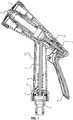
FIG. 1 is a cross-section view of an inner part of an anti-freezing water spray gun having a water sealing position at a distal end when the water is sealed at a distal end; -
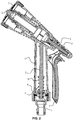
FIG. 2 is a cross-section view of an inner part of an anti-freezing water spray gun having a water sealing position at a distal end when the water is not sealed at a distal end; -
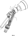
FIG. 3 is a first stereogram of an anti-freezing water spray gun having a water sealing position at a distal end; -
FIG. 4 is a second stereogram of an anti-freezing water spray gun having a water sealing position at a distal end; -
FIG. 5 is a stereogram of an inner part of an anti-freezing water spray gun having a water sealing position at a distal end with a outer casing being removed; -
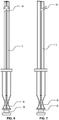
FIG. 6 is a front view of an water stop plug of a distal end; -
FIG. 7 is a left view of an water stop plug of a distal end; -
FIG. 8 is a rear view of an water stop plug of a distal end; -
FIG. 9 is a right view of an water stop plug of a distal end; -
FIG. 10 is a first stereogram of an water stop plug of a distal end; -
FIG. 11 is a second stereogram of an water stop plug of a distal end; -
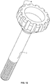
FIG. 12 is a first stereogram of a pull rod provided with a plug; -
FIG. 13 is a second stereogram of a pull rod provided with a plug; -
FIG. 14 is a stereogram of a spray bar; -
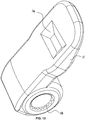
FIG. 15 is a stereogram of a lock button; -
FIG. 16 is a stereogram of a second sealing ring for introducing water; -
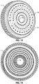
FIG. 17 is a stereogram of a water spray plate; -
FIG. 18 is a front view of a water spray plate; -
FIG. 19 is a rear view of a water spray plate; -
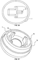
FIG. 20 is a top view of an water stop plug of a distal end; and -
FIG. 21 is a stereogram of a water stop plate. - In the drawings, the following numbers are used: 1. First sealing ring for stopping water; 2. Water stop plug of a distal end; 2a. Oblique limiting piece; 2b.Seal groove; 2c. Deflection strips; 2d. Push head; 3. Gun body; 4. Handle; 5. Pull rod; 5a. Plug; 6. Spray bar; 6a. Spray head; 6b. Oblate nozzle; 6c. Guide surface; 7. Water spray plate; 7a. Triangular holes; 8. Water stop plate; 8a. Curved plates; 8b. Positioning ring; 9. Water stop spring; 10. Lock button; 10a. Recess; 10b. Convex-concave knurls; 11. Second sealing ring for introducing water; and 11a. Convex pieces.
- For further illustrating the invention, experiments detailing anti-freezing water spray gun having a water sealing position at a distal end are described hereinbelow combined with the drawings.
- An anti-freezing water spray gun having a water sealing position at a distal end, comprises a
gun body 3. The gun body comprises: an inner part, the inner part comprising a water channel; an outer part, the outer part comprising ahandle 4; an upper part, the upper part comprising aspray bar 6, awater spray plate 7, alock button 10, and apull rod 5 comprising a plug; and a lower part, the lower part comprising anwater stop plug 2 disposed at an distal end thereof, awater stop plate 8, awater stop spring 9, afirst sealing ring 1 for stopping water, and asecond sealing ring 11 for introducing water. The water channel is disposed in the inner part of thegun body 3. Thehandle 4 is movably mounted on the outer part of thegun body 3 via a pin. In conventional water spray gun, the water sealing position is disposed near the position of the plug, and water residues still remains in the gun body, which results freezing or even rupture of the gun body. However, the water spray gun of the invention is capable of sealing the water at a water sealing position of the distal end for keeping the water out of the gun body and for preventing the gun body from being frozen and ruptured after the water spray gun being closed. The pull rod is pulled backward when the handle is pressed down, the water stop plug moves downwardly under the force of the plug and drives the second sealing ring for introducing water to move outward to allow the water spray gun to stay at an open state. The water enters the gun body and is sprayed out via thespray bar 6 and thewater spray plate 7. The handle is pressed by thelock button 10 for continuously spraying water. The lock button is in movable rivet connection with the gun body for locking the handle during water spraying. A rivet hole of the lock button is provided with convex-concave knurls for preventing looseness. The lock button is provided with a recess for preventing a finger from slipping from the lock button. The pull rod is reset under the force of the spring when the handle is released and the water stop plug is reset under the force of thewater stop spring 9, the first sealing ring for stopping water is driven to move forward, the water is sealed outside the gun body, and the water spray gun is at a closed state for keeping the water outside thereof. The plug and thewater stop plug 2 of the distal end cooperate when the water spray gun is closed to allow thewater stop plate 8 and thefirst sealing ring 1 to seal the water at the distal end for keeping the water out of the gun body and preventing the gun body from being frozen and ruptured. - The
pull rod 5 comprises theplug 5a in the shape of a cone. Theplug 5a comprises: a front circle comprising a plurality of teeth for allowing the water to flow out, and a conical head being connected to thepull rod 5. A generating line of a curved surface of the cone of theplug 5a is an equiangular spiral featuring in equivalent pressure angles, that is, a logarithmic spiral. An equiangular spiral surface of theplug 5a is capable of stably matching with apush head 2d arranged on an upper part of thewater stop plug 2 of the distal end. - In the above technical solution, the generating line of the curved surface of the cone of the
plug 5a is the equiangular spiral featuring in equivalent pressure angles, that is, the logarithmic spiral. A section of a main body of the pull rod is selected, and a differential equation dρ/dθ=kρ is constructed as follows: a polar coordinates equation ρ=ρ(θ) is defined, as the pressure angle λ is desired to be equivalent everywhere, tgλ is evaluated with a constant value, and herein tgλ=k. According to the equation of the pressure angle tgλ=ρ'/ρ ρ'/ρ=k is derived. A differential equation dρ/dθ=kρ is derived by differential calculus. - To solve the differential equation dρ/dθ=kρ, the variables are separated and integral calculus are performed on both sides of the equation: ∫dρ/ρ=∫kdθ, since ρ>0, lnρ=kθ+C is obtained, that is, an exponential equation is ρ=Aekθ+C=eC, and ekθ=Aekθ.
- Drawing software PRO/ENGINEER WILDFIRE is adopted. A new working directory is started, and new components are constructed.
-
PARAMETER 1 is constructed: C is a real number and is a default assignment; -
PARAMETER 2 is constructed: N is an integer and is a default assignment; and - Relations are constructed, and the equations of the invention are as follows: a logarithmic curve: z=0; x = 10*t; and y = log(10*t+0.0001). The logarithmic curve is then drawn.
- After that, a model is constructed by using instructions comprising revolution, merger, and materialization, and by performing work piece assembly and combination.
- The equations and the model constructed by PRO/ENGINEER WILDFIRE are input into a CNC machining center, CIMATRO or MASTCAM are used to press a steel model for casting aluminum alloy, or a milling machine, facing machine, are an electric spark machining are used auxiliarily. When the electric spark machining is used, the equations are input into the CNC machining center. A tungsten copper electrode is required to be prepared, an ideal machine used herein is provided with three-dimensional rotating heads, for example, a Charmilles machine made in Sweden is preferred. After that, a cold chamber die casting machine or a hot chamber die casting machine is used for batch production, followed with machine work. Most workpiece are made of ZL109 or AC8A aluminum alloy and are polished. As the generating line of the curved surface of the cone of the
plug 5a is a part of the equiangular spiral featuring in equivalent pressure angles, that is, the logarithmic spiral, the equiangular spiral surface of theplug 5a is capable of stably matching with thepush head 2d arranged on the upper part of thewater stop plug 2 of the distal end. - A
seal groove 2b is disposed at a lower part of thewater stop plug 2 of the distal end for fitting with thefirst sealing ring 1. - Four deflection strips 2c are arranged at a lower part of the
water stop plug 2 of the distal end and uniformly surround an axis of a reciprocating direction of thewater stop plug 2. A curve line of each of the fourdeflection strips 2c is a deflection curve satisfying a deflection curve equation concerning a load density q and a bending stiffness EJ in mechanics of materials. - An oblique limiting
piece 2a is arranged at an upper part of thewater stop plug 2, an included angle between the oblique limitingpiece 2a and an axis of a reciprocating direction of the upper part of thewater stop plug 2 is between 30° and 80° for limiting a position thereof. - A
push head 2d is arranged at an upper part of thewater stop plug 2 for matching with theplug 5a of thepull rod 5. - Two
curved plates 8a are symmetrically disposed inside thewater stop plate 8 for matching with thewater stop spring 9 and fourdeflection strips 2c arranged at a lower part of thewater stop plug 2 of the distal end. Apositioning ring 8b in the shape of an ellipse is disposed at an outer part of thewater stop plate 8 for preventing rotation. Through holes are arranged in thewater stop plate 8 for matching with thefirst sealing ring 1. - The
water spray plate 7 is provided with a plurality oftriangular holes 7a, each triangular hole is in the shape of a triangle. The triangular holes are arranged in three concentric circles, and conical holes are arranged among the concentric circles. - Three
convex pieces 11a are disposed on an outer ring of thesecond sealing ring 11 for introducing water at different horizontal planes. The arrangement of the threeconvex pieces 11a is in accordance with a helicoidal surface of a water inlet thread for attenuating a twisted stress and ensuring a sealing property. - Advantages of the invention are as follows:
First, thelock button 10 is in movable rivet connection with the gun body for locking thehandle 4 during water spraying. The rivet hole of thelock button 10 is provided with convex-concave knurls 10b for preventing looseness. Thelock button 10 is provided with
therecess 10a for preventing the finger from slipping from thelock button 10. Thus, the structure of the water spray gun of the invention is very convenient. - Second, when the handle is released, the pull rod is reset under the force of the spring and the water stop plug is reset under the force of the
water stop spring 9, the first sealing ring for stopping water is driven to move forward, the water is sealed outside the gun body, and the water spray gun is at the closed state for keeping the water outside thereof. The plug and thewater stop plug 2 of the distal end cooperate when the water spray gun is closed to allow thewater stop plate 8 and the first sealing ring for stopping water to seal the water at the distal end for keeping the water out of the gun body and preventing the gun body from being frozen and ruptured. Theplug 5a comprises: the front circle comprising the teeth for allowing the water to flow out, and the conical head being connected to thepull rod 5. The generating line of the curved surface of the cone of theplug 5a is the equiangular spiral featuring in equivalent pressure angles, that is, logarithmic spiral. Thus, the equiangular spiral surface of theplug 5a stably matches with thepush head 2d arranged on the upper part of thewater stop plug 2 of the distal end. The water spray gun of the invention solves the problem in conventional water spray guns that the water sealing position is disposed near the plug and water residue remains in the gun body when the water spray gun is closed, which easily results in freezing and rupture of the water spray gun. - Third, the
water spray plate 7 is provided with thetriangular holes 7a arranged in three concentric circles, and conic holes are arranged among the concentric circles. Thespray bar 6 comprises aguide surface 6c andoblate nozzles 6b. In spraying the water, thespray bar 6 slightly trembles under the combined force of theguide surface 6c, the plug, and the water jet. The water is ejected from thespray bar 6 via the oblate nozzles arranged on thespray bar 6, and is sprayed out via thespray head 6a of the spray bar and the triangular holes and the conic holes arranged on the spray plate, so that the pattern of the sprayed water is diversified. - Fourth, the conventional second sealing ring for introducing water is made of rubber and generally comprises three convex pieces arranged in the common horizontal plane, however, as the workpiece mounted thereon is provided with threads having a pitch, a helix angle, and a lead, so that when the conventional second sealing ring for introducing water comprising three convex pieces arranged on the common horizontal plane is mounted on the thread, the twisted internal stress is produced, thereby affecting the sealing property of the inner ring of the sealing ring. To solve the problem, the three convex pieces of the invention is arranged in accordance with the pitch of the thread. For example, if the pitch is equal to 1.5, then the height of each convex piece is increased by 0.5. As the three convex pieces of the outer ring of the
second sealing ring 11 for introducing water are distributed at different heights according to the water inlet thread, the twisted stress is decreased and the sealing property is ensured. - In summary, first, the arrangement of the convex-concave knurl on the rivet hole of the
lock button 10 is designed for the purpose of antislipping; the recess is disposed on the lock button, so that even the wet finger is capable of holding the lock button. Second, compared with the conventional water spray gun that easily causes freezing and rupture of the gun body since water residue remains therein when the water spray gun is closed, the water spray gun of the invention effectively overcomes such problem. When the handle of the water spray gun is released, the pull rod is reset, the first sealing ring for stopping water is driven to move forward since equiangular spiral surface of theplug 5a stably matches with apush head 2d of thewater stop plug 2 of the distal end. The water is prevented out of the gun body, and the water spray gun is at the closed state for keeping the water outside thereof. Third, thewater spray plate 7 is provided with triangular holes, thereby forming diversified patterns of the sprayed water. Fourth, the convex pieces of the outer ring of the first sealing ring for stopping water have proper pitch, helix angle, and lead for preventing the twisted internal stress.
Claims (9)
- A water spray gun, comprising a gun body (3), the gun body (3) comprising:a)an inner part, the inner part comprising a water channel;b)an outer part, the outer part comprising a handle (4);c) an upper part, the upper part comprising an outer surface, a spray bar (6), a water spray plate (7), a lock button (10), and a pull rod (5) comprising a plug; andd)a lower part, the lower part comprising a water stop plug (2) disposed at an distal end thereof, a water stop plate (8), a water stop spring (9), a first sealing ring (1) for stopping water, and a second sealing ring (11) for introducing water;wherein the water channel is disposed in the inner part of the gun body (3), and the handle (4) is movably mounted on the outer part of the gun body (3) via a pin;
characterized in that
the lock button (10) comprises a rivet hole, a first end, a second end, a first surface, and a second surface;
a recess (10a) is disposed on the first surface of the lock button (10);
the rivet hole is disposed at the second end of the lock button (10);
a plurality of convex-concave knurls (10b) is disposed on an inner surface of the second end of the lock button (10) that confines the rivet hole;
the lock button (10) is disposed on the outer surface of the upper part and is in movable rivet connection with the gun body (3);
the lock button (10) is movable between a first position and a second position;
when the lock button (10) is disposed at the first position, the second surface of the lock button (10) is in contact with the outer surface of the upper part;
when the lock button (10) is disposed at the second position, the second surface of the lock button (10) is not in contact with the outer surface of the upper part, and the first end of the lock button (10) clamps and locks the handle (4); and
a user contacts the first surface of the lock button (10) and the recess (10a) when moving the lock button (10) from the first position towards the second position. - The water spray gun of claim 1, characterized in thatthe plug (5a) of the pull rod (5) is in the shape of a cone;the plug (5a) comprises: a front circle comprising a plurality of teeth for allowing the water to flow out, and a conical head being connected to the pull rod (5);a generating line of a curved surface of the cone of the plug (5a) is an equiangular spiral; andan equiangular spiral surface of the plug (5a) is capable of stably matching with a push head (2d) arranged on an upper part of the water stop plug (2) of the distal end.
- The water spray gun of claim 1, characterized in that a seal groove (2b) is disposed at a lower part of the water stop plug (2) of the distal end for fitting with the first sealing ring (1) for stopping water.
- The water spray gun of claim 1, characterized in thatfour deflection strips (2c) are arranged at a lower part of the water stop plug (2) of the distal end and uniformly surround an axis of a reciprocating direction of the water stop plug (2); anda curve line of each of the four deflection strips (2c) is a deflection curve.
- The water spray gun of claim 1, characterized in that an oblique limiting piece (2a) is arranged at an upper part of the water stop plug (2), and an included angle between the oblique limiting piece (2a) and an axis of a reciprocating direction of the upper part of the water stop plug (2) is between 30° and 80° for limiting a position thereof.
- The water spray gun of claim 1, characterized in that a push head (2d) is arranged at an upper part of the water stop plug (2) for matching with the plug (5a) of the pull rod (5).
- The water spray gun of claim 1, characterized in thattwo curved plates (8a) are symmetrically disposed inside the water stop plate (8) for matching with the water stop spring (9) and four deflection strips (2c) arranged at a lower part of the water stop plug (2) of the distal end;a positioning ring (8b) in the shape of an ellipse is disposed at an outer part of the water stop plate (8) for preventing rotation; andthrough holes are arranged in the water stop plate (8) for matching with the first sealing ring (1).
- The water spray gun of claim 1, characterized in that the water spray plate (7) is provided with a plurality of triangular holes (7a) and a plurality of conical holes; the plurality of triangular holes (7a) is arranged in three concentric circles, and the plurality of conical holes is arranged among the three concentric circles.
- The water spray gun of claim 1, characterized in thatthree convex pieces (11a) are disposed on an outer ring of the second sealing ring (11) at different horizontal planes;the arrangement of the three convex pieces (11a) is in accordance with a helicoidal surface of a water inlet thread for decreasing a twisted stress and ensuring a sealing property.
Applications Claiming Priority (1)
| Application Number | Priority Date | Filing Date | Title |
|---|---|---|---|
| CN201310334055.1A CN103406224B (en) | 2013-08-01 | 2013-08-01 | A kind of hydraulic giant of antifreeze far-end sealing |
Publications (2)
| Publication Number | Publication Date |
|---|---|
| EP2832450A1 EP2832450A1 (en) | 2015-02-04 |
| EP2832450B1 true EP2832450B1 (en) | 2018-12-19 |
Family
ID=49599292
Family Applications (1)
| Application Number | Title | Priority Date | Filing Date |
|---|---|---|---|
| EP14162616.8A Not-in-force EP2832450B1 (en) | 2013-08-01 | 2014-03-31 | Water spray gun |
Country Status (4)
| Country | Link |
|---|---|
| US (1) | US9174232B2 (en) |
| EP (1) | EP2832450B1 (en) |
| JP (1) | JP5866108B2 (en) |
| CN (1) | CN103406224B (en) |
Families Citing this family (13)
| Publication number | Priority date | Publication date | Assignee | Title |
|---|---|---|---|---|
| CN104084328B (en) * | 2014-06-03 | 2017-01-18 | 宁波大叶园林科技有限公司 | Water saving method adopting improved pressure compensating emitter |
| CN104475284A (en) * | 2014-12-08 | 2015-04-01 | 宁波大叶园林科技有限公司 | Stepless-control antifreezing park water pistol |
| CN104521688A (en) * | 2014-12-08 | 2015-04-22 | 宁波大叶园林科技有限公司 | Throw-button self-locking stepless adjustable garden irrigation water nozzle |
| CN104858083B (en) * | 2015-05-27 | 2017-03-01 | 宁波大叶园林科技有限公司 | Screw mandrel adjusts anti-ice and freezes gardens water pistol |
| USD780892S1 (en) * | 2016-01-22 | 2017-03-07 | Graco Minnesota Inc. | Spray gun |
| CN109070107B (en) * | 2016-05-13 | 2021-05-11 | 阿尔弗雷德·卡赫欧洲两合公司 | Valve Guns for High Pressure Cleaners |
| CN106994402B (en) * | 2017-05-19 | 2022-07-29 | 徐州海伦哲专用车辆股份有限公司 | Special water gun for electrified water washing |
| CN108128281B (en) * | 2017-12-28 | 2024-03-08 | 珠海格力智能装备有限公司 | Spray gun and car washer with same |
| USD929540S1 (en) * | 2019-07-10 | 2021-08-31 | Shin Tai Spurt Water Of The Garden Tools Co., Ltd. | Handheld spray gun |
| KR102317176B1 (en) * | 2020-05-11 | 2021-10-25 | 주식회사 세경인프라 | Water gun capable of direct and spiral water spray |
| US11642684B2 (en) * | 2020-05-20 | 2023-05-09 | Yuan-Mei Corp. | Water spray gun for control of outflow of water and adjustment of outflow |
| USD946117S1 (en) * | 2020-11-05 | 2022-03-15 | Shin Tai Spurt Water Of The Garden Tools Co., Ltd. | Gardening sprayer |
| CN118122509A (en) * | 2024-04-15 | 2024-06-04 | 中山市庆谊金属制品企业有限公司 | A kind of anti-freezing water gun structure |
Citations (1)
| Publication number | Priority date | Publication date | Assignee | Title |
|---|---|---|---|---|
| DE202012100323U1 (en) * | 2012-01-31 | 2012-05-11 | Ningbo Daye Garden Industry Co., Ltd. | spray gun |
Family Cites Families (13)
| Publication number | Priority date | Publication date | Assignee | Title |
|---|---|---|---|---|
| JPH01104361A (en) * | 1987-10-14 | 1989-04-21 | Toshio Takagi | Water spray nozzle |
| JPH0742517Y2 (en) * | 1990-05-09 | 1995-10-04 | 株式会社トヨックス | Sprinkler |
| JPH11114454A (en) * | 1997-10-13 | 1999-04-27 | Sanyo Kasei:Kk | Nozzle for water spray |
| JP2912321B1 (en) * | 1998-01-05 | 1999-06-28 | 株式会社トヨックス | Watering nozzle |
| US6173910B1 (en) * | 1999-10-14 | 2001-01-16 | Chya Ye Industrial Co., Ltd. | Press structure of washing head for kitchen cabinet |
| JP4358948B2 (en) * | 1999-11-26 | 2009-11-04 | 株式会社三栄水栓製作所 | Sprinkler |
| US6454187B1 (en) * | 2001-05-23 | 2002-09-24 | Hsin-Fa Wang | Water emission control structure of gardening pistol nozzle |
| US6641061B1 (en) * | 2002-10-08 | 2003-11-04 | Max Hsieh | Spray assembly for use in a kitchen |
| GB0319698D0 (en) * | 2003-08-21 | 2003-09-24 | Hozelock Ltd | Hose guns |
| US20070080242A1 (en) * | 2005-10-11 | 2007-04-12 | Xuedong Wang | Faucet side spray with metal plated exterior and interior structures, and with inert internal waterway |
| US20120061490A1 (en) * | 2010-09-14 | 2012-03-15 | William Yiu Man Chung | Hand held spray valve |
| JP5645805B2 (en) * | 2011-12-12 | 2014-12-24 | 株式会社タカギ | Watering nozzle |
| CN102553757B (en) * | 2011-12-27 | 2014-02-19 | 宁波大叶园林工业有限公司 | Water spray gun locked by slide button |
-
2013
- 2013-08-01 CN CN201310334055.1A patent/CN103406224B/en active Active
-
2014
- 2014-03-31 EP EP14162616.8A patent/EP2832450B1/en not_active Not-in-force
- 2014-04-01 US US14/242,833 patent/US9174232B2/en active Active
- 2014-04-19 JP JP2014086945A patent/JP5866108B2/en active Active
Patent Citations (1)
| Publication number | Priority date | Publication date | Assignee | Title |
|---|---|---|---|---|
| DE202012100323U1 (en) * | 2012-01-31 | 2012-05-11 | Ningbo Daye Garden Industry Co., Ltd. | spray gun |
Also Published As
| Publication number | Publication date |
|---|---|
| CN103406224A (en) | 2013-11-27 |
| US9174232B2 (en) | 2015-11-03 |
| JP5866108B2 (en) | 2016-02-17 |
| EP2832450A1 (en) | 2015-02-04 |
| US20150034740A1 (en) | 2015-02-05 |
| JP2015029989A (en) | 2015-02-16 |
| CN103406224B (en) | 2015-10-21 |
Similar Documents
| Publication | Publication Date | Title |
|---|---|---|
| EP2832450A1 (en) | Water spray gun | |
| EP2792416B1 (en) | Water spray gun | |
| CN109940557A (en) | The axial nailing device of quick ejection | |
| CN113042245B (en) | a spray gun | |
| CN106103001B (en) | Pyrotechnic driving devices | |
| CN104521688A (en) | Throw-button self-locking stepless adjustable garden irrigation water nozzle | |
| CN110548614A (en) | Rear trigger adjustment nozzle with quick adjustable spray | |
| CN110538737A (en) | Rear trigger multi-section water gun capable of quickly adjusting flow | |
| CN104475284A (en) | Stepless-control antifreezing park water pistol | |
| CN108014935A (en) | A kind of pressure linear regulation combination nozzle and high-pressure cleaning device | |
| CN218742747U (en) | Liquid medicine sprayer with anti-blocking effect | |
| US2721923A (en) | Nozzle | |
| CN104858083B (en) | Screw mandrel adjusts anti-ice and freezes gardens water pistol | |
| CN205674142U (en) | Abaculus formula axial nailing device | |
| CN109059636B (en) | Tear-promoting multifunctional ultralong stick for police | |
| CN107913808B (en) | A kind of antidrip high-low pressure combination nozzle and high-pressure cleaning device | |
| CN223234076U (en) | Cleaning water gun | |
| CN207886273U (en) | Pedicle of vertebral arch screw nails on nail device | |
| CN214286369U (en) | Carbon dioxide fire extinguishing device of straightening machine | |
| CN214234583U (en) | Auxiliary electromagnetic inflating pump filter | |
| CN224230840U (en) | Multifunctional ejection riot stick | |
| CN216396731U (en) | Spray gun shower head with single-key switch switching function | |
| CN206587951U (en) | A kind of novel spraying spray gun | |
| CN223115125U (en) | Handle sleeve assembly for nail shooter and nail shooter | |
| CN212747508U (en) | Explosion-proof stick capable of ejecting tear gas |
Legal Events
| Date | Code | Title | Description |
|---|---|---|---|
| 17P | Request for examination filed |
Effective date: 20140331 |
|
| AK | Designated contracting states |
Kind code of ref document: A1 Designated state(s): AL AT BE BG CH CY CZ DE DK EE ES FI FR GB GR HR HU IE IS IT LI LT LU LV MC MK MT NL NO PL PT RO RS SE SI SK SM TR |
|
| AX | Request for extension of the european patent |
Extension state: BA ME |
|
| PUAI | Public reference made under article 153(3) epc to a published international application that has entered the european phase |
Free format text: ORIGINAL CODE: 0009012 |
|
| R17P | Request for examination filed (corrected) |
Effective date: 20150713 |
|
| RBV | Designated contracting states (corrected) |
Designated state(s): AL AT BE BG CH CY CZ DE DK EE ES FI FR GB GR HR HU IE IS IT LI LT LU LV MC MK MT NL NO PL PT RO RS SE SI SK SM TR |
|
| GRAP | Despatch of communication of intention to grant a patent |
Free format text: ORIGINAL CODE: EPIDOSNIGR1 |
|
| STAA | Information on the status of an ep patent application or granted ep patent |
Free format text: STATUS: GRANT OF PATENT IS INTENDED |
|
| RIC1 | Information provided on ipc code assigned before grant |
Ipc: B05B 12/00 20060101ALI20180705BHEP Ipc: B05B 1/16 20060101ALN20180705BHEP Ipc: B05B 9/01 20060101ALI20180705BHEP Ipc: B05B 1/30 20060101AFI20180705BHEP Ipc: B05B 1/14 20060101ALN20180705BHEP |
|
| INTG | Intention to grant announced |
Effective date: 20180807 |
|
| GRAS | Grant fee paid |
Free format text: ORIGINAL CODE: EPIDOSNIGR3 |
|
| GRAA | (expected) grant |
Free format text: ORIGINAL CODE: 0009210 |
|
| STAA | Information on the status of an ep patent application or granted ep patent |
Free format text: STATUS: THE PATENT HAS BEEN GRANTED |
|
| AK | Designated contracting states |
Kind code of ref document: B1 Designated state(s): AL AT BE BG CH CY CZ DE DK EE ES FI FR GB GR HR HU IE IS IT LI LT LU LV MC MK MT NL NO PL PT RO RS SE SI SK SM TR |
|
| REG | Reference to a national code |
Ref country code: GB Ref legal event code: FG4D |
|
| REG | Reference to a national code |
Ref country code: CH Ref legal event code: EP |
|
| REG | Reference to a national code |
Ref country code: IE Ref legal event code: FG4D |
|
| REG | Reference to a national code |
Ref country code: DE Ref legal event code: R096 Ref document number: 602014038089 Country of ref document: DE |
|
| REG | Reference to a national code |
Ref country code: AT Ref legal event code: REF Ref document number: 1078115 Country of ref document: AT Kind code of ref document: T Effective date: 20190115 |
|
| REG | Reference to a national code |
Ref country code: NL Ref legal event code: MP Effective date: 20181219 |
|
| PG25 | Lapsed in a contracting state [announced via postgrant information from national office to epo] |
Ref country code: LT Free format text: LAPSE BECAUSE OF FAILURE TO SUBMIT A TRANSLATION OF THE DESCRIPTION OR TO PAY THE FEE WITHIN THE PRESCRIBED TIME-LIMIT Effective date: 20181219 Ref country code: NO Free format text: LAPSE BECAUSE OF FAILURE TO SUBMIT A TRANSLATION OF THE DESCRIPTION OR TO PAY THE FEE WITHIN THE PRESCRIBED TIME-LIMIT Effective date: 20190319 Ref country code: FI Free format text: LAPSE BECAUSE OF FAILURE TO SUBMIT A TRANSLATION OF THE DESCRIPTION OR TO PAY THE FEE WITHIN THE PRESCRIBED TIME-LIMIT Effective date: 20181219 Ref country code: LV Free format text: LAPSE BECAUSE OF FAILURE TO SUBMIT A TRANSLATION OF THE DESCRIPTION OR TO PAY THE FEE WITHIN THE PRESCRIBED TIME-LIMIT Effective date: 20181219 Ref country code: BG Free format text: LAPSE BECAUSE OF FAILURE TO SUBMIT A TRANSLATION OF THE DESCRIPTION OR TO PAY THE FEE WITHIN THE PRESCRIBED TIME-LIMIT Effective date: 20190319 Ref country code: HR Free format text: LAPSE BECAUSE OF FAILURE TO SUBMIT A TRANSLATION OF THE DESCRIPTION OR TO PAY THE FEE WITHIN THE PRESCRIBED TIME-LIMIT Effective date: 20181219 |
|
| REG | Reference to a national code |
Ref country code: LT Ref legal event code: MG4D |
|
| REG | Reference to a national code |
Ref country code: AT Ref legal event code: MK05 Ref document number: 1078115 Country of ref document: AT Kind code of ref document: T Effective date: 20181219 |
|
| PG25 | Lapsed in a contracting state [announced via postgrant information from national office to epo] |
Ref country code: GR Free format text: LAPSE BECAUSE OF FAILURE TO SUBMIT A TRANSLATION OF THE DESCRIPTION OR TO PAY THE FEE WITHIN THE PRESCRIBED TIME-LIMIT Effective date: 20190320 Ref country code: AL Free format text: LAPSE BECAUSE OF FAILURE TO SUBMIT A TRANSLATION OF THE DESCRIPTION OR TO PAY THE FEE WITHIN THE PRESCRIBED TIME-LIMIT Effective date: 20181219 Ref country code: SE Free format text: LAPSE BECAUSE OF FAILURE TO SUBMIT A TRANSLATION OF THE DESCRIPTION OR TO PAY THE FEE WITHIN THE PRESCRIBED TIME-LIMIT Effective date: 20181219 Ref country code: RS Free format text: LAPSE BECAUSE OF FAILURE TO SUBMIT A TRANSLATION OF THE DESCRIPTION OR TO PAY THE FEE WITHIN THE PRESCRIBED TIME-LIMIT Effective date: 20181219 |
|
| PG25 | Lapsed in a contracting state [announced via postgrant information from national office to epo] |
Ref country code: NL Free format text: LAPSE BECAUSE OF FAILURE TO SUBMIT A TRANSLATION OF THE DESCRIPTION OR TO PAY THE FEE WITHIN THE PRESCRIBED TIME-LIMIT Effective date: 20181219 |
|
| PG25 | Lapsed in a contracting state [announced via postgrant information from national office to epo] |
Ref country code: PL Free format text: LAPSE BECAUSE OF FAILURE TO SUBMIT A TRANSLATION OF THE DESCRIPTION OR TO PAY THE FEE WITHIN THE PRESCRIBED TIME-LIMIT Effective date: 20181219 Ref country code: PT Free format text: LAPSE BECAUSE OF FAILURE TO SUBMIT A TRANSLATION OF THE DESCRIPTION OR TO PAY THE FEE WITHIN THE PRESCRIBED TIME-LIMIT Effective date: 20190419 Ref country code: ES Free format text: LAPSE BECAUSE OF FAILURE TO SUBMIT A TRANSLATION OF THE DESCRIPTION OR TO PAY THE FEE WITHIN THE PRESCRIBED TIME-LIMIT Effective date: 20181219 Ref country code: CZ Free format text: LAPSE BECAUSE OF FAILURE TO SUBMIT A TRANSLATION OF THE DESCRIPTION OR TO PAY THE FEE WITHIN THE PRESCRIBED TIME-LIMIT Effective date: 20181219 Ref country code: IT Free format text: LAPSE BECAUSE OF FAILURE TO SUBMIT A TRANSLATION OF THE DESCRIPTION OR TO PAY THE FEE WITHIN THE PRESCRIBED TIME-LIMIT Effective date: 20181219 |
|
| PG25 | Lapsed in a contracting state [announced via postgrant information from national office to epo] |
Ref country code: RO Free format text: LAPSE BECAUSE OF FAILURE TO SUBMIT A TRANSLATION OF THE DESCRIPTION OR TO PAY THE FEE WITHIN THE PRESCRIBED TIME-LIMIT Effective date: 20181219 Ref country code: EE Free format text: LAPSE BECAUSE OF FAILURE TO SUBMIT A TRANSLATION OF THE DESCRIPTION OR TO PAY THE FEE WITHIN THE PRESCRIBED TIME-LIMIT Effective date: 20181219 Ref country code: SM Free format text: LAPSE BECAUSE OF FAILURE TO SUBMIT A TRANSLATION OF THE DESCRIPTION OR TO PAY THE FEE WITHIN THE PRESCRIBED TIME-LIMIT Effective date: 20181219 Ref country code: IS Free format text: LAPSE BECAUSE OF FAILURE TO SUBMIT A TRANSLATION OF THE DESCRIPTION OR TO PAY THE FEE WITHIN THE PRESCRIBED TIME-LIMIT Effective date: 20190419 Ref country code: SK Free format text: LAPSE BECAUSE OF FAILURE TO SUBMIT A TRANSLATION OF THE DESCRIPTION OR TO PAY THE FEE WITHIN THE PRESCRIBED TIME-LIMIT Effective date: 20181219 |
|
| REG | Reference to a national code |
Ref country code: DE Ref legal event code: R097 Ref document number: 602014038089 Country of ref document: DE |
|
| PLBE | No opposition filed within time limit |
Free format text: ORIGINAL CODE: 0009261 |
|
| STAA | Information on the status of an ep patent application or granted ep patent |
Free format text: STATUS: NO OPPOSITION FILED WITHIN TIME LIMIT |
|
| PG25 | Lapsed in a contracting state [announced via postgrant information from national office to epo] |
Ref country code: MC Free format text: LAPSE BECAUSE OF FAILURE TO SUBMIT A TRANSLATION OF THE DESCRIPTION OR TO PAY THE FEE WITHIN THE PRESCRIBED TIME-LIMIT Effective date: 20181219 Ref country code: AT Free format text: LAPSE BECAUSE OF FAILURE TO SUBMIT A TRANSLATION OF THE DESCRIPTION OR TO PAY THE FEE WITHIN THE PRESCRIBED TIME-LIMIT Effective date: 20181219 Ref country code: DK Free format text: LAPSE BECAUSE OF FAILURE TO SUBMIT A TRANSLATION OF THE DESCRIPTION OR TO PAY THE FEE WITHIN THE PRESCRIBED TIME-LIMIT Effective date: 20181219 |
|
| REG | Reference to a national code |
Ref country code: CH Ref legal event code: PL |
|
| 26N | No opposition filed |
Effective date: 20190920 |
|
| GBPC | Gb: european patent ceased through non-payment of renewal fee |
Effective date: 20190331 |
|
| PG25 | Lapsed in a contracting state [announced via postgrant information from national office to epo] |
Ref country code: LU Free format text: LAPSE BECAUSE OF NON-PAYMENT OF DUE FEES Effective date: 20190331 |
|
| REG | Reference to a national code |
Ref country code: BE Ref legal event code: MM Effective date: 20190331 |
|
| PG25 | Lapsed in a contracting state [announced via postgrant information from national office to epo] |
Ref country code: LI Free format text: LAPSE BECAUSE OF NON-PAYMENT OF DUE FEES Effective date: 20190331 Ref country code: GB Free format text: LAPSE BECAUSE OF NON-PAYMENT OF DUE FEES Effective date: 20190331 Ref country code: CH Free format text: LAPSE BECAUSE OF NON-PAYMENT OF DUE FEES Effective date: 20190331 Ref country code: IE Free format text: LAPSE BECAUSE OF NON-PAYMENT OF DUE FEES Effective date: 20190331 |
|
| PG25 | Lapsed in a contracting state [announced via postgrant information from national office to epo] |
Ref country code: BE Free format text: LAPSE BECAUSE OF NON-PAYMENT OF DUE FEES Effective date: 20190331 Ref country code: SI Free format text: LAPSE BECAUSE OF FAILURE TO SUBMIT A TRANSLATION OF THE DESCRIPTION OR TO PAY THE FEE WITHIN THE PRESCRIBED TIME-LIMIT Effective date: 20181219 |
|
| PG25 | Lapsed in a contracting state [announced via postgrant information from national office to epo] |
Ref country code: TR Free format text: LAPSE BECAUSE OF FAILURE TO SUBMIT A TRANSLATION OF THE DESCRIPTION OR TO PAY THE FEE WITHIN THE PRESCRIBED TIME-LIMIT Effective date: 20181219 |
|
| PG25 | Lapsed in a contracting state [announced via postgrant information from national office to epo] |
Ref country code: MT Free format text: LAPSE BECAUSE OF NON-PAYMENT OF DUE FEES Effective date: 20190331 |
|
| PG25 | Lapsed in a contracting state [announced via postgrant information from national office to epo] |
Ref country code: CY Free format text: LAPSE BECAUSE OF FAILURE TO SUBMIT A TRANSLATION OF THE DESCRIPTION OR TO PAY THE FEE WITHIN THE PRESCRIBED TIME-LIMIT Effective date: 20181219 |
|
| PG25 | Lapsed in a contracting state [announced via postgrant information from national office to epo] |
Ref country code: HU Free format text: LAPSE BECAUSE OF FAILURE TO SUBMIT A TRANSLATION OF THE DESCRIPTION OR TO PAY THE FEE WITHIN THE PRESCRIBED TIME-LIMIT; INVALID AB INITIO Effective date: 20140331 |
|
| PG25 | Lapsed in a contracting state [announced via postgrant information from national office to epo] |
Ref country code: MK Free format text: LAPSE BECAUSE OF FAILURE TO SUBMIT A TRANSLATION OF THE DESCRIPTION OR TO PAY THE FEE WITHIN THE PRESCRIBED TIME-LIMIT Effective date: 20181219 |
|
| PGFP | Annual fee paid to national office [announced via postgrant information from national office to epo] |
Ref country code: FR Payment date: 20230321 Year of fee payment: 10 |
|
| PGFP | Annual fee paid to national office [announced via postgrant information from national office to epo] |
Ref country code: DE Payment date: 20230508 Year of fee payment: 10 |
|
| REG | Reference to a national code |
Ref country code: DE Ref legal event code: R119 Ref document number: 602014038089 Country of ref document: DE |
|
| PG25 | Lapsed in a contracting state [announced via postgrant information from national office to epo] |
Ref country code: DE Free format text: LAPSE BECAUSE OF NON-PAYMENT OF DUE FEES Effective date: 20241001 |
|
| PG25 | Lapsed in a contracting state [announced via postgrant information from national office to epo] |
Ref country code: FR Free format text: LAPSE BECAUSE OF NON-PAYMENT OF DUE FEES Effective date: 20240331 |
|
| PG25 | Lapsed in a contracting state [announced via postgrant information from national office to epo] |
Ref country code: FR Free format text: LAPSE BECAUSE OF NON-PAYMENT OF DUE FEES Effective date: 20240331 Ref country code: DE Free format text: LAPSE BECAUSE OF NON-PAYMENT OF DUE FEES Effective date: 20241001 |