EP2832407A1 - Image display device and program - Google Patents
Image display device and program Download PDFInfo
- Publication number
- EP2832407A1 EP2832407A1 EP20140156201 EP14156201A EP2832407A1 EP 2832407 A1 EP2832407 A1 EP 2832407A1 EP 20140156201 EP20140156201 EP 20140156201 EP 14156201 A EP14156201 A EP 14156201A EP 2832407 A1 EP2832407 A1 EP 2832407A1
- Authority
- EP
- European Patent Office
- Prior art keywords
- opening
- transparent plate
- wall
- display device
- image display
- Prior art date
- Legal status (The legal status is an assumption and is not a legal conclusion. Google has not performed a legal analysis and makes no representation as to the accuracy of the status listed.)
- Withdrawn
Links
Images





Classifications
-
- G—PHYSICS
- G09—EDUCATION; CRYPTOGRAPHY; DISPLAY; ADVERTISING; SEALS
- G09F—DISPLAYING; ADVERTISING; SIGNS; LABELS OR NAME-PLATES; SEALS
- G09F9/00—Indicating arrangements for variable information in which the information is built-up on a support by selection or combination of individual elements
-
- G—PHYSICS
- G09—EDUCATION; CRYPTOGRAPHY; DISPLAY; ADVERTISING; SEALS
- G09F—DISPLAYING; ADVERTISING; SIGNS; LABELS OR NAME-PLATES; SEALS
- G09F19/00—Advertising or display means not otherwise provided for
- G09F19/12—Advertising or display means not otherwise provided for using special optical effects
-
- A—HUMAN NECESSITIES
- A63—SPORTS; GAMES; AMUSEMENTS
- A63H—TOYS, e.g. TOPS, DOLLS, HOOPS OR BUILDING BLOCKS
- A63H33/00—Other toys
- A63H33/22—Optical, colour, or shadow toys
-
- B—PERFORMING OPERATIONS; TRANSPORTING
- B65—CONVEYING; PACKING; STORING; HANDLING THIN OR FILAMENTARY MATERIAL
- B65D—CONTAINERS FOR STORAGE OR TRANSPORT OF ARTICLES OR MATERIALS, e.g. BAGS, BARRELS, BOTTLES, BOXES, CANS, CARTONS, CRATES, DRUMS, JARS, TANKS, HOPPERS, FORWARDING CONTAINERS; ACCESSORIES, CLOSURES, OR FITTINGS THEREFOR; PACKAGING ELEMENTS; PACKAGES
- B65D25/00—Details of other kinds or types of rigid or semi-rigid containers
-
- G—PHYSICS
- G02—OPTICS
- G02B—OPTICAL ELEMENTS, SYSTEMS OR APPARATUS
- G02B27/00—Optical systems or apparatus not provided for by any of the groups G02B1/00 - G02B26/00, G02B30/00
- G02B27/01—Head-up displays
- G02B27/0149—Head-up displays characterised by mechanical features
-
- G—PHYSICS
- G02—OPTICS
- G02B—OPTICAL ELEMENTS, SYSTEMS OR APPARATUS
- G02B27/00—Optical systems or apparatus not provided for by any of the groups G02B1/00 - G02B26/00, G02B30/00
- G02B27/02—Viewing or reading apparatus
- G02B27/022—Viewing apparatus
-
- G—PHYSICS
- G02—OPTICS
- G02B—OPTICAL ELEMENTS, SYSTEMS OR APPARATUS
- G02B27/00—Optical systems or apparatus not provided for by any of the groups G02B1/00 - G02B26/00, G02B30/00
- G02B27/10—Beam splitting or combining systems
- G02B27/14—Beam splitting or combining systems operating by reflection only
-
- G—PHYSICS
- G02—OPTICS
- G02B—OPTICAL ELEMENTS, SYSTEMS OR APPARATUS
- G02B27/00—Optical systems or apparatus not provided for by any of the groups G02B1/00 - G02B26/00, G02B30/00
- G02B27/10—Beam splitting or combining systems
- G02B27/14—Beam splitting or combining systems operating by reflection only
- G02B27/144—Beam splitting or combining systems operating by reflection only using partially transparent surfaces without spectral selectivity
-
- H—ELECTRICITY
- H04—ELECTRIC COMMUNICATION TECHNIQUE
- H04N—PICTORIAL COMMUNICATION, e.g. TELEVISION
- H04N13/00—Stereoscopic video systems; Multi-view video systems; Details thereof
- H04N13/30—Image reproducers
-
- G—PHYSICS
- G02—OPTICS
- G02B—OPTICAL ELEMENTS, SYSTEMS OR APPARATUS
- G02B27/00—Optical systems or apparatus not provided for by any of the groups G02B1/00 - G02B26/00, G02B30/00
- G02B27/01—Head-up displays
- G02B27/0149—Head-up displays characterised by mechanical features
- G02B2027/0161—Head-up displays characterised by mechanical features characterised by the relative positioning of the constitutive elements
-
- H—ELECTRICITY
- H04—ELECTRIC COMMUNICATION TECHNIQUE
- H04M—TELEPHONIC COMMUNICATION
- H04M1/00—Substation equipment, e.g. for use by subscribers
- H04M1/02—Constructional features of telephone sets
- H04M1/0202—Portable telephone sets, e.g. cordless phones, mobile phones or bar type handsets
-
- H—ELECTRICITY
- H04—ELECTRIC COMMUNICATION TECHNIQUE
- H04M—TELEPHONIC COMMUNICATION
- H04M1/00—Substation equipment, e.g. for use by subscribers
- H04M1/02—Constructional features of telephone sets
- H04M1/0202—Portable telephone sets, e.g. cordless phones, mobile phones or bar type handsets
- H04M1/026—Details of the structure or mounting of specific components
- H04M1/0266—Details of the structure or mounting of specific components for a display module assembly
Definitions
- the present invention relates to an image display device and a program.
- JP-A Japanese Unexamined Patent Application Publication
- Fig. 4 of JP-A No. 8-122695 illustrates an image device with which a viewer may view a synthesized image obtained by superimposing a background image behind a half mirror and passing through the half mirror and an image reflected on the half mirror on each other.
- the half mirror used in the image device of JP-A No. 8-122695 is produced by depositing a metal reflective layer such as a chromium or SUS layer as thin as possible, almost translucent, at least on one side of a glass material. Therefore, the half mirror is relatively expensive.
- the half mirror described in JP-A No. 8-122695 has reflectance of 50% and transmittance of 50%. Although these numerical values are examples, transmittance of the background image is typically low in the half mirror because of the existence of the metal reflective layer.
- the present invention provides an image display device and a program capable of displaying an image, such as 3D hologram, at a relatively lower cost without using a half mirror.
- An image display device includes a transparent plate having transparency and capable of being disposed in an inclined manner with respect to a display section of a portable terminal provided with the display section, in which a display displayed on the display section is capable of being reflected on the transparent plate.
- the transparent plate may be made of glass or resin, the resin being polyvinyl chloride, polyethylene terephthalate, polycarbonate, acrylic resin, or the like.
- the image display device may further include a support section which is capable of supporting the portable terminal from the display section side.
- the transparent plate may be situated below the portable terminal supported by the support section.
- the image display device includes an object, in which the transparent plate may be situated further toward a user than the object.
- the object may be replaceable.
- the object may be stereoscopic.
- the image display device may further include a side wall situated on a side of the transparent plate.
- a pair of side walls may be disposed on both sides of the transparent plate.
- the image display device may further include a front wall situated between the transparent plate and a user.
- the front wall may have an opening from which the user is capable of viewing the transparent plate.
- the front wall may include a side edge wall which is disposed on a side of the opening and defines an opening width of the opening.
- the front wall may include two side edge walls which are disposed on both sides of the opening and define the opening width of the opening.
- the image display device may further include a rear wall situated on the opposite side of the user with respect to the transparent plate.
- the pair of side walls may be capable of supporting the portable terminal from the display section side.
- a pair of side walls may be disposed on both sides of the transparent plate; the pair of side walls may be capable of supporting the portable terminal from the display section side; and the pair of side walls may serve also as the support section.
- the image display device may further include a side wall situated on a side of the transparent plate and a front wall situated between the transparent plate and a user, in which the side wall and the front wall may be capable of supporting the portable terminal from the display section side.
- the image display device may further include a side wall situated on a side of the transparent plate and a front wall situated between the transparent plate and a user, in which the side wall and the front wall may be capable of supporting the portable terminal from the display section side and in which the side wall and the front wall may serve also as the support section.
- the front wall may have an opening from which the user is capable of viewing the transparent plate.
- the front wall may include a side edge wall which is disposed on a side of the opening and defines an opening width of the opening.
- the front wall may include two side edge walls which are disposed on both sides of the opening and define the opening width of the opening.
- the image display device may further includes a side wall situated on a side of the transparent plate and a rear wall situated on the opposite side of a user with respect to the transparent plate, in which the side wall and the rear wall may be capable of supporting the portable terminal from the display section side.
- the image display device may further include a side wall situated on a side of the transparent plate and a rear wall situated on the opposite side of a user with respect to the transparent plate, in which the side wall and the rear wall may be capable of supporting the portable terminal from the display section side and in which the side wall and the rear wall may serve also as the support section.
- the image display device may further include a front wall situated between the transparent plate and a user and a rear wall which faces the front wall, in which the front wall and the rear wall may be capable of supporting the portable terminal from the display section side.
- the image display device may further include a front wall situated between the transparent plate and a user and a rear wall which faces the front wall, in which the front wall and the rear wall may be capable of supporting the portable terminal from the display section side and in which the front wall and the rear wall may serve also as the support section.
- the front wall may have an opening from which the user is capable of viewing the transparent plate.
- the front wall may include a side edge wall which is disposed on a side of the opening and defines an opening width of the opening.
- the front wall may include two side edge walls which are disposed on both sides of the opening and define the opening width of the opening.
- the image display device according to the present invention may also include a bottom wall.
- the image display device may further include a box body which includes a bottom wall and a pair of side walls disposed on both sides of the transparent plate.
- the box body may have a front opening situated between the transparent plate and a user.
- the box body may include a side edge wall which is disposed on a side of the front opening and defines an opening width of the front opening.
- the box body may include two side edge walls which are disposed on both sides of the front opening and define the opening width of the front opening.
- the box body may have an upper opening which faces the bottom wall.
- the image display device may further include a placement section which defines an angle of the transparent plate.
- the object may include a side stopper which positions the transparent plate in a width direction.
- a packaging container includes the image display device and a lid body which covers the upper opening and the front opening of the box body, in which an article may be capable of being contained in a space surrounded by the box body and the lid body.
- Fig. 1 is a schematic perspective view of a packaging container according to an embodiment of the present invention.
- a packaging container 1 includes a box body 10, a stereoscopic object 20, a transparent plate (i.e., a clear card) 30, and a lid body 40.
- goods or articles (not illustrated), such as candies and toys, may be contained together with the stereoscopic object 20 and the transparent plate 30, and the box body 10 is covered by the lid body 40 from above.
- the box body 10 may be used as the packaging container 1 for various goods.
- the box body 10 includes a bottom wall 11 on which the stereoscopic object 20 is placed, a rear wall 12 disposed behind the stereoscopic object 20, and side walls 13 and 13 extending forward from the rear wall 12 at both sides of the stereoscopic object 20.
- the box body 10 has an upper opening 15 which faces the bottom wall 11, and a front opening 16 which faces the rear wall 12.
- the box body 10 further includes a front wall 14 which faces the rear wall 12.
- the front wall 14 includes two side edge walls 14A and 14B disposed at both sides of the front opening 16 to define an opening width of the front opening 16.
- the front wall 14 may further include a lower edge wall 14C which stands up from the bottom wall 11 to define a lower end of the front opening 16.
- a height L1 of the box body 10 is lower than a length L2 of the transparent plate 30 (L1 ⁇ L2).
- a height L3 of the lid body 40 is higher than a length L2 of the transparent plate 30 (L1 ⁇ L2 ⁇ L3).
- the lid body 40 has, for example, a shape of a lid box body with its lower end open.
- the lid body 40 includes folding pieces 41 and 41 which are folded and made to adhere to the bottom wall 11 of the box body 10 using an adhesive tape or the like, whereby the lid body 40 is mounted on and fixed to the box body 10.
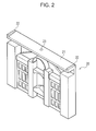
- the stereoscopic object 20 includes projections and recesses on the front thereof as illustrated in Fig. 2 .
- the example illustrated in Fig. 2 is a stereoscopic object of a building.
- the stereoscopic object 20 is not limited to a building but may be various characters and figures.
- the stereoscopic object 20 may be made of resin or metal, or may be a paper craft.
- the stereoscopic object 20 may be fixed to the rear wall 12 of the box body 10. Alternatively, the stereoscopic object 20 may be taken out of the packaging container 1 and disposed back to back on the rear wall 12.
- non-stereoscopic objects such as a card and a wall on which a background is drawn, may also be used.
- the object may be replaceable. Further, the object and the rear wall 12 may be removed so that actual scenery and an actual building may be viewed through the transparent plate 30. In that case, the image display displayed on the transparent plate 30 may be viewed in a superimposed manner on the actual scenery and the actual building which are viewed through the transparent plate 30.
- the transparent plate 30 is formed as a thin plate by a material transparent (i.e., having transparency) to the wavelength bands of visible light, such as glass or resin.
- the transparent plate 30 is desirably formed by compact of resin, such as polyvinyl chloride (PVC), polyethylene terephthalate (PET), polycarbonate (PC), or acrylic resin, from the standpoint of difficulty in damaging and reduction in weight.
- Polyethylene terephthalate is desirable from the standpoint of a low production cost.
- thickness of the transparent plate 30 equal to or thicker than 0.4 mm is desirable from the standpoint of intensity.
- the thickness of the transparent plate 30 is desirably equal to or lower than 0.6 mm as a surface on which an image is reflected and on which an image is displayed. As illustrated in Fig.
- a placement section 21 on which the upper end portion 31 of the transparent plate 30 may be placed is formed on an upper surface of the stereoscopic object 20.
- the placement section 21 is formed as, for example, an inclined surface inclined downward toward the front.
- an angle of the transparent plate 30 is defined such that an image on a display section 110 (see Fig. 5 ) is superimposed at a surface position of the stereoscopic object 20 viewed through the transparent plate 30, thereby providing a clearer image to a user.
- the inclined surface inclined downward toward the front is used as the placement section.
- the position and shape of the placement section are not limited to such an inclined surface as long as positioning in which the image of the display section 110 is superimposed at a surface position of the stereoscopic object 20 viewed through the transparent plate 30 is achieved.
- a placement section which may fix the upper end portion 31 of the transparent plate 30 may be provided at a front side of the stereoscopic object 20, or a placement section may be provided in the box body.
- two side stoppers 22 and 22 projecting upward at both ends in the width direction of the placement section 21 may be provided on the upper surface of the stereoscopic object 20. These two side stoppers 22 and 22 may position the transparent plate 30 in the width direction.
- the side stoppers may be provided in the box body.
- the lower end portion 32 of the transparent plate 30 is locked at a corner at which the bottom wall 11 and the front wall 14 (14A to 14C) of the box body 10 cross each other as illustrated in Fig. 3 .
- Figs. 3 and 5 illustrate a usage condition of an image display device in which a portable terminal (for example, a smartphone) 100 provided with the display section 110 illustrated in Fig. 6 is placed on top of the side walls 13 and 13 of the box body 10 with the display section 110 facing below (i.e., the portable terminal 100 is supported from the side of the display section 110).
- the image display device is configured by assembling among the members illustrated in Fig. 1 the box body 10, the stereoscopic object 20, and the transparent plate 30, excluding the lid body 40, as illustrated in Figs. 3 and 5 .
- Fig. 7 illustrates an example of image display viewed from the front opening 16 in the usage condition of the image display device illustrated in Figs. 3 and 5 . As illustrated in Fig.
- the transparent plate 30 is visible from the front opening 16.
- the portable terminal is supported by the box body and may be supported by at least two wall surface portions among the side walls 13 and 13, the rear wall 12, and the front wall 14. That is, in the present embodiment, at least two wall surfaces supporting the portable terminal 100, i.e., at least two wall surfaces among the side walls 13 and 13, the rear wall 12, and the front wall 14 serve also as a "support section" of the present invention.
- the wall surfaces of the box body do not necessarily serve also as the "support section” and the "support section” of the present invention may be provided separately. It is sufficient that the "support section" which may support the portable terminal 100 from the side of the display section 110 is provided. It is further desirable that, with the support section, the transparent plate 30 is situated below the display section 110 of the portable terminal 100.
- an image Im2 of the display section 110 of the portable terminal 100 reflected on the transparent plate 30 is superimposed on a perspective stereoscopic image Im1 of the stereoscopic object 20 entering from behind the transparent plate 30 and viewed through the transparent plate 30.
- the side behind the transparent plate 30 at which the stereoscopic object 20 is disposed is surrounded by the stereoscopic object 20, the side walls 13 and 13, and the portable terminal 100, the side behind the transparent plate 30 is darker than the side of the front opening 16 in front of the transparent plate 30.
- the stereoscopic object 20 For a viewer who directly views the stereoscopic object 20 (i.e., the dark side) from the front opening 16 side in front of the transparent plate 30 (i.e., from the light side), the stereoscopic object 20 may be viewed through the transparent plate 30 and, at the same time, the viewer may also view the image Im2 of the display section 110 of the portable terminal 100 that is reflected on the transparent plate 30 (i.e., displayed on the transparent plate 30).
- the image display device of the present embodiment includes light and dark difference generating means (in the present embodiment, any one of or a combination of the stereoscopic object 20, the side walls 13 and 13, the bottom wall 11, the front wall 14, the rear wall 12, and the portable terminal 100) which may produce via the transparent plate 30 a difference in light and dark between one space (i.e., a space in which the user exists with respect to the transparent plate 30: in front of the transparent plate 30 in the present embodiment) and the other space (i.e., a space on the opposite side of the user with respect to the transparent plate 30: behind the transparent plate 30 in the present embodiment).
- one space i.e., a space in which the user exists with respect to the transparent plate 30: in front of the transparent plate 30 in the present embodiment
- the other space i.e., a space on the opposite side of the user with respect to the transparent plate 30: behind the transparent plate 30 in the present embodiment.
- the user may view the side behind the transparent plate 30 (i.e., the space on the opposite side of the user with respect to the transparent plate 30) through the transparent plate 30 and, at the same time, the user may view the image Im2 of the display section 110 of the portable terminal 100 reflected on the transparent plate 30 (i.e., displayed on the transparent plate 30).
- This phenomenon on the transparent plate 30 is the same as a phenomenon on a car window at night on which an occupant's face is superimposed on a scene viewed through the car window. Since the transparent plate 30 is disposed in an inclined manner, the transparent plate 30 may reflect and display the image of the display section 110 to the viewer.
- the image of the display section 110 reflected on the transparent plate 30 may be superimposed on the stereoscopic object 20 viewed through the transparent plate 30 with relatively high transmittance without using a half mirror.
- the transparent plate 30 may be formed by laminating a plurality of transparent thin plates 30A to 30C.
- each of interfaces between the plurality of transparent thin plates 30A, 30B, and 30C functions as a reflecting layer and thus reflectance may be increased. Since the transmittance decreases as a result of increased reflectance, the space behind the transparent plate 30 becomes darker and the effect of the above phenomenon via the transparent plate 30 is increased.
- a reflected image 122 obtained by reflecting an image 120 of the display section 110 on two transparent thin plates 30A and 30B as illustrated in Fig. 8B is clearer than a reflected image 121 obtained by reflecting an image 120 of the display section 110 on a single transparent thin plate 30A as illustrated in Fig. 8A .
- a thickness of each of the transparent thin plates 30A to 30C may be equal to or smaller than 0.45 mm. If each of the transparent thin plates 30A to 30C is thicker than 0.45 mm, position misalignment is caused between the reflected images on different interfaces as illustrated in Fig. 4 , and blur in a composite reflected image becomes noticeable. If the transparent plate 30 is made of resin, when formability is considered, the thickness of each of the transparent thin plates 30A to 30C may be 0.15 mm to 0.45 mm.
- the number of transparent thin plates to be laminated is desirably two to four when the thickness mentioned above is considered; If the number of transparent thin plates to be laminated is greater than four, position misalignment is caused between the reflected images on different interfaces, and blur in a composite reflected image becomes noticeable.
- the transparent plate 30 or the plurality of transparent thin plates 30A to 30C may be colored gray or the like. By coloring the transparent plate 30 or the plurality of transparent thin plates 30A to 30C, transmittance of the transparent plate 30 or the plurality of transparent thin plates 30A to 30C may be lowered; and by making the space behind the transparent plate 30 or the plurality of transparent thin plates 30A to 30C darker, reflectance on the transparent plate 30 may be increased.
- the plurality of transparent thin plates 30A to 30C may be fixed in a laminated state to increase handleability.
- the plurality of transparent thin plates 30A to 30C may be fixed by welding (including ultrasonic welding), adhering, pressure bonding, or fixing with a frame.
- the image displayed on the display section 110 of the portable terminal 100 illustrated in Fig. 6 may be a still image or may be a moving image.
- a moving image 120B of which display position, shape, color, and the like change with time is displayed as projection mapping on the background stereoscopic object 20 together with a still image 120A of the same color and outline as those of a front image of the stereoscopic object 20.
- a viewing angle at the front opening 16 of the image display device is limited by the side edge walls 14A and 14B. Therefore, even if the display section 110 of the portable terminal 100 is a liquid crystal display section or the like, the viewing angle at the front opening 16 of the display device may be adapted to a viewing angle of the liquid crystal display section. Since the field of view at the front opening 16 of the image display device is limited by the side edge walls 14A and 14B and the lower edge wall 14C, unnecessary backgrounds of the bottom wall 11, side walls 13 and 13, and the like of the box body 10 may be hidden.
- the transparent plate 30 is situated below the display section 110 of the supported portable terminal 100. Then, unless the user lifts the image display device above the eye line and tries to view inside the front opening 16 from below (viewing from below is not a normal usage situation because the space behind the transparent plate 30 (i.e., the rear side: the space on the opposite side of the user with respect to the transparent plate 30) is not easily viewed from the front opening 16), the display on the display section 110 of the portable terminal 100 is not easily viewed by the user. Therefore, a situation in which the user views both the image display on the transparent plate 30 and the display section 110 of the portable terminal 100 and loses interest may be reduced.
- a marker may be provided in the box body 10, the stereoscopic object 20, or the display section 110.
- a marker 23 is provided at, for example, the center in the width direction on the upper surface of the stereoscopic object 20 in Figs. 1 to 3 .
- a centerline of the display section 110 of the portable terminal 100 may be aligned with the marker 23.
- Fig. 9 illustrates markers 130 to 133 displayed on the display section 110 of the portable terminal 100.
- the marker 130 may be displayed at a position corresponding to the marker 23 provided in the stereoscopic object 20.
- the marker 131 is aligned with the side walls 13 and 13 of the box body 10.
- the marker 132 is aligned with the rear wall 12 of the box body 10.
- the marker 133 is aligned with the side edge walls 14A and 14B of the box body 10.
- the display section 110 may display one or more of markers 130 to 133.
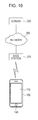
- a base station 210 which communicates with the portable terminal 100 is connected to a server 220 via a network 200.
- the portable terminal 100 includes an acquisition section 150 connected to a camera 140 illustrated in Fig. 9 other than the display section 110.
- the camera 140 of the portable terminal 100 reads QR code (registered trademark) 17 which is a 2D code provided in the box body 10 as illustrated in Fig. 1 , and the read code information is acquired by the acquisition section 150.
- the portable terminal 100 further includes an input section 160 for inputting an icon or the like to be displayed on the display section 110, and a communication section 170.
- the communication section 170 communicates with the server 220 using a URL included in the QR code (registered trademark) 17, which is access information of the server 220.
- the server 220 includes a communication section 221 and a storage section 222 as illustrated in Fig. 12 .
- the server 220 executes the following Procedures 1 and 2 in accordance with a program stored in the storage section 222 to the portable terminal 100 accessed on the basis of the QR code (registered trademark) 17.
- the server 220 reads data of an image of at least one marker among the markers 130 to 133 illustrated in Fig. 9 from the storage section 222 and transmits the data to the portable terminal 100 via the communication section 221, the network 200, and the base station 210.
- the server 220 reads data of the images 120A and 120B illustrated in Fig. 6 from the storage section 222 and transmits the data to the portable terminal 100 via the communication section 221, the network 200, and the base station 210.
- the server 220 may let the image of the marker of Procedure 1 be displayed on the display section 110 of the portable terminal 100 for a predetermined initial time and then proceed to Procedure 2. That is, after the portable terminal 100 is aligned using the markers 130 to 133 displayed by Procedure 1, the markers 130 to 133 are not displayed.
- the server 220 may let the image of the marker of Procedure 1 be displayed on the display section 110 of the portable terminal 100 for a predetermined initial time and then execute Procedures 1 and 2 in parallel. That is, the image of the marker may be displayed as an initial image, or continuously displayed with the images 120A and 120B illustrated in Fig. 6 .
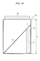
- a box body 10A illustrated in Fig. 13 may integrally include a first lid body 42 which covers an upper opening 15 and a second lid body 43 which covers a front opening 16.
- the first lid body 42 and the second lid body 43 are connected to the box body 10A via, for example, perforation lines and are separated from the box body 10A at the time of use.
- the transparent plate 30 having the length L2 may be contained at a vertical position in the box body 10A.
- a placement section for placing the upper end portion 31 of the transparent plate 30 may also be provided on a rear wall 12A of the box body 10A instead of the stereoscopic object 20.
- an image display device comprising a transparent plate 30 having transparency and capable of being disposed in an inclined manner with respect to a display section 110 of a portable terminal provided with the display section 110, wherein a display displayed on the display section 110 is capable of being reflected on the transparent plate 30.
- the transparent plate 30 is made of glass or resin, the resin including polyvinyl chloride, polyethylene terephthalate, polycarbonate, and acrylic resin.
- the image display device according to the first or second construction, further comprising a support section capable of supporting the portable terminal from the display section 110 side.
- a fourth construction there is disclosed the image display device according to the third construction, wherein the transparent plate 30 is situated below the portable terminal supported by the support section.
- the image display device according to any one of the first to fourth constructions, further comprising an object 20, wherein the transparent plate 30 is situated further toward a user than the object 20.
- a seventh construction there is disclosed the image display device according to the fifth or sixth construction, wherein the object 20 is stereoscopic.
- the image display device according to any one of the first to seventh constructions, further comprising a side wall 13 situated on a side of the transparent plate 30.
- a ninth construction there is disclosed the image display device according to any one of the first to seventh constructions, wherein a pair of side walls 13, 13 are disposed on both sides of the transparent plate 30.
- the image display device according to any one of the first to ninth constructions, further comprising a front wall 14 situated between the transparent plate 30 and a user.
- an eleventh construction there is disclosed the image display device according to the tenth construction, wherein the front wall 14 has an opening 16 from which the user is capable of viewing the transparent plate 30.
- the image display device according to the eleventh construction, wherein the front wall 14 includes a side edge wall which is disposed on a side of the opening 16 and defines an opening width of the opening 16.
- the image display device according to the eleventh construction, wherein the front wall 14 includes two side edge walls which are disposed on both sides of the opening 16 and define the opening width of the opening 16.
- a fourteenth construction there is disclosed the image display device according to any one of the first to thirteenth constructions, further comprising a rear wall 12 situated on the opposite side of the user with respect to the transparent plate 30.
- the image display device according to the ninth construction, wherein the pair of side walls 13, 13 are capable of supporting the portable terminal from the display section 110 side.
- the image display device according to any one of the first to seventh constructions, further comprising a side wall 13 situated on a side of the transparent plate 30 and a front wall 14 situated between the transparent plate 30 and a user, wherein the side wall 13 and the front wall 14 are capable of supporting the portable terminal from the display section 110 side.
- the image display device according to the third or fourth construction, further comprising a side wall 13 situated on a side of the transparent plate 30 and a front wall 14 situated between the transparent plate 30 and a user, wherein the side wall 13 and the front wall 14 are capable of supporting the portable terminal from the display section 110 side and wherein the side wall 13 and the front wall 14 serve also as the support section.
- the image display device according to the seventeenth or eighteenth construction, wherein the front wall 14 has an opening 16 from which the user is capable of viewing the transparent plate 30.
- the image display device according to the nineteenth construction, wherein the front wall 14 includes a side edge wall which is disposed on a side of the opening 16 and defines an opening width of the opening 16.
- the image display device according to the nineteenth construction, wherein the front wall 14 includes two side edge walls which are disposed on both sides of the opening 16 and define the opening width of the opening 16.
- the image display device according to any one of the first to seventh constructions, further comprising a side wall 13 situated on a side of the transparent plate 30 and a rear wall 12 situated on the opposite side of a user with respect to the transparent plate 30, wherein the side wall 13 and the rear wall 12 are capable of supporting the portable terminal from the display section 110 side.
- the image display device according to the third or fourth construction, further comprising a side wall 13 situated on a side of the transparent plate 30 and a rear wall 12 situated on the opposite side of a user with respect to the transparent plate 30, wherein the side wall 13 and the rear wall 12 are capable of supporting the portable terminal from the display section 110 side and wherein the side wall 13 and the rear wall 12 serve also as the support section.
- the image display device according to any one of the first to seventh constructions, further comprising a front wall 14 situated between the transparent plate 30 and a user and a rear wall 12 which faces the front wall 14, wherein the front wall 14 and the rear wall 12 are capable of supporting the portable terminal from the display section 110 side.
- the image display device according to the third or fourth construction, further comprising a front wall 14 situated between the transparent plate 30 and a user and a rear wall 12 which faces the front wall 14, wherein the front wall 14 and the rear wall 12 are capable of supporting the portable terminal from the display section 110 side and wherein the front wall 14 and the rear wall 12 serve also as the support section.
- the image display device according to the twenty-fourth or twenty-fifth construction, wherein the front wall 14 has an opening 16 from which the user is capable of viewing the transparent plate 30.
- the image display device according to the twenty-sixth construction, wherein the front wall 14 includes a side edge wall which is disposed on a side of the opening 16 and defines an opening width of the opening 16.
- the image display device according to the twenty-sixth construction, wherein the front wall 14 includes two side edge walls which are disposed on both sides of the opening 16 and define the opening width of the opening 16.
- the image display device according to any one of the first to twenty-eighth constructions, further comprising a bottom wall 11.
- the image display device according to any one of the first to seventh constructions, further comprising a box body 10 which includes a bottom wall 11 and a pair of side walls 13, 13 disposed on both sides of the transparent plate 30.
- the image display device according to the thirtieth construction, wherein the box body 10 has a front opening 16 situated between the transparent plate 30 and a user.
- the box body 10 includes a side edge wall which is disposed on a side of the front opening 16 and defines an opening width of the front opening 16.
- the box body 10 includes two side edge walls which are disposed on both sides of the front opening 16 and define the opening width of the front opening 16.
- the image display device according to any one of the thirtieth to thirty-third constructions, wherein the box body 10 has an upper opening 15 which faces the bottom wall 11.
- the image display device according to any one of the first to thirty-fourth constructions, further comprising a placement section which defines an angle of the transparent plate 30.
- the image display device according to any one of the fifth to seventh constructions, wherein the object 20 includes a side stopper which positions the transparent plate 30 in a width direction.
- a packaging container comprising the image display device according to the thirty-fourth construction and a lid body 40 which covers the upper opening 15 and the front opening 16 of the box body 10, wherein an article is capable of being contained in a space surrounded by the box body 10 and the lid body 40.
Landscapes
- Physics & Mathematics (AREA)
- General Physics & Mathematics (AREA)
- Optics & Photonics (AREA)
- Engineering & Computer Science (AREA)
- Theoretical Computer Science (AREA)
- Spectroscopy & Molecular Physics (AREA)
- Mechanical Engineering (AREA)
- Multimedia (AREA)
- Signal Processing (AREA)
- Business, Economics & Management (AREA)
- Accounting & Taxation (AREA)
- Marketing (AREA)
- Devices For Indicating Variable Information By Combining Individual Elements (AREA)
Abstract
An image display device includes a transparent plate (30) which may be disposed in an inclined manner with respect to a display section (110) of a portable terminal provided with the display section (110). A display displayed on the display section (110) may be reflected on the transparent plate (30). A space behind the transparent plate (30) may be viewed through the transparent plate (30) and, at the same time, an image on the display section (110) of the portable terminal may also be viewed while being reflected on the transparent plate (30).
Description
- The present invention relates to an image display device and a program.
- An image display device in which two images are superimposed on each other using a half mirror is proposed (see, for example, Japanese Unexamined Patent Application Publication (JP-A) No.
8-122695 Fig. 4 ofJP-A No. 8-122695 - The half mirror used in the image device of
JP-A No. 8-122695 - The half mirror described in
JP-A No. 8-122695 - The present invention provides an image display device and a program capable of displaying an image, such as 3D hologram, at a relatively lower cost without using a half mirror.
- An image display device according to the present invention includes a transparent plate having transparency and capable of being disposed in an inclined manner with respect to a display section of a portable terminal provided with the display section, in which a display displayed on the display section is capable of being reflected on the transparent plate.
- In the image display device according to the present invention, the transparent plate may be made of glass or resin, the resin being polyvinyl chloride, polyethylene terephthalate, polycarbonate, acrylic resin, or the like.
- The image display device according to the present invention may further include a support section which is capable of supporting the portable terminal from the display section side.
- In the image display device according to the present invention, the transparent plate may be situated below the portable terminal supported by the support section.
- The image display device according to the present invention includes an object, in which the transparent plate may be situated further toward a user than the object.
- In the image display device according to the present invention, the object may be replaceable.
- In the image display device according to the present invention, the object may be stereoscopic.
- The image display device according to the present invention may further include a side wall situated on a side of the transparent plate.
- In the image display device according to the present invention, a pair of side walls may be disposed on both sides of the transparent plate.
- The image display device according to the present invention may further include a front wall situated between the transparent plate and a user.
- In the image display device according to the present invention, the front wall may have an opening from which the user is capable of viewing the transparent plate.
- In the image display device according to the present invention, the front wall may include a side edge wall which is disposed on a side of the opening and defines an opening width of the opening.
- In the image display device according to the present invention, the front wall may include two side edge walls which are disposed on both sides of the opening and define the opening width of the opening.
- The image display device according to the present invention may further include a rear wall situated on the opposite side of the user with respect to the transparent plate.
- In the image display device according to the present invention, the pair of side walls may be capable of supporting the portable terminal from the display section side.
- In the image display device according to the present invention, a pair of side walls may be disposed on both sides of the transparent plate; the pair of side walls may be capable of supporting the portable terminal from the display section side; and the pair of side walls may serve also as the support section.
- The image display device according to the present invention may further include a side wall situated on a side of the transparent plate and a front wall situated between the transparent plate and a user, in which the side wall and the front wall may be capable of supporting the portable terminal from the display section side.
- The image display device according to the present invention may further include a side wall situated on a side of the transparent plate and a front wall situated between the transparent plate and a user, in which the side wall and the front wall may be capable of supporting the portable terminal from the display section side and in which the side wall and the front wall may serve also as the support section.
- In the image display device according to the present invention, the front wall may have an opening from which the user is capable of viewing the transparent plate.
- In the image display device according to the present invention, the front wall may include a side edge wall which is disposed on a side of the opening and defines an opening width of the opening.
- In the image display device according to the present invention, the front wall may include two side edge walls which are disposed on both sides of the opening and define the opening width of the opening.
- The image display device according to the present invention may further includes a side wall situated on a side of the transparent plate and a rear wall situated on the opposite side of a user with respect to the transparent plate, in which the side wall and the rear wall may be capable of supporting the portable terminal from the display section side.
- The image display device according to the present invention may further include a side wall situated on a side of the transparent plate and a rear wall situated on the opposite side of a user with respect to the transparent plate, in which the side wall and the rear wall may be capable of supporting the portable terminal from the display section side and in which the side wall and the rear wall may serve also as the support section.
- The image display device according to the present invention may further include a front wall situated between the transparent plate and a user and a rear wall which faces the front wall, in which the front wall and the rear wall may be capable of supporting the portable terminal from the display section side.
- The image display device according to the present invention may further include a front wall situated between the transparent plate and a user and a rear wall which faces the front wall, in which the front wall and the rear wall may be capable of supporting the portable terminal from the display section side and in which the front wall and the rear wall may serve also as the support section.
- In the image display device according to the present invention, the front wall may have an opening from which the user is capable of viewing the transparent plate.
- In the image display device according to the present invention, the front wall may include a side edge wall which is disposed on a side of the opening and defines an opening width of the opening.
- In the image display device according to the present invention, the front wall may include two side edge walls which are disposed on both sides of the opening and define the opening width of the opening.
- The image display device according to the present invention may also include a bottom wall.
- The image display device according to the present invention may further include a box body which includes a bottom wall and a pair of side walls disposed on both sides of the transparent plate.
- In the image display device according to the present invention, the box body may have a front opening situated between the transparent plate and a user.
- In the image display device according to the present invention, the box body may include a side edge wall which is disposed on a side of the front opening and defines an opening width of the front opening.
- In the image display device according to the present invention, the box body may include two side edge walls which are disposed on both sides of the front opening and define the opening width of the front opening.
- In the image display device according to the present invention, the box body may have an upper opening which faces the bottom wall.
- The image display device according to the present invention may further include a placement section which defines an angle of the transparent plate.
- In the image display device according to the present invention, the object may include a side stopper which positions the transparent plate in a width direction.
- A packaging container according to the present invention includes the image display device and a lid body which covers the upper opening and the front opening of the box body, in which an article may be capable of being contained in a space surrounded by the box body and the lid body.
-
-
Fig. 1 is a schematic perspective view of a packaging container (including an image display device and a lid body) according to an embodiment of the present invention; -
Fig. 2 is a perspective view of a stereoscopic object; -
Fig. 3 is a cross-sectional view illustrating a usage condition in which a portable terminal is placed on the image display device; -
Fig. 4 is an enlarged view of section IV ofFig. 3 ; -
Fig. 5 is a perspective view illustrating a usage condition of the image display device; -
Fig. 6 is a diagram illustrating an image on a display section of the portable terminal; -
Fig. 7 is a diagram illustrating an image displayed in the image display device; -
Fig. 8A illustrates a reflected image when a single transparent thin plate is used; -
Fig. 8B is a diagram illustrating a reflected image when a plurality of transparent thin plates are used; -
Fig. 9 is a diagram illustrating a marker displayed on the display section of the portable terminal; -
Fig. 10 is a diagram illustrating a network to which a base station communicating with the portable terminal and a server are connected; -
Fig. 11 is a functional block diagram of the portable terminal; -
Fig. 12 is a functional block diagram of the server; -
Fig. 13 is a perspective view illustrating a modification of a packaging container in which a box body and a lid body are integrated with each other in a separable manner; and -
Fig. 14 is a cross-sectional view illustrating an image display device using the box body illustrated inFig. 13 . -
Fig. 1 is a schematic perspective view of a packaging container according to an embodiment of the present invention. As illustrated inFig. 1 , apackaging container 1 includes abox body 10, astereoscopic object 20, a transparent plate (i.e., a clear card) 30, and alid body 40. In thebox body 10, goods or articles (not illustrated), such as candies and toys, may be contained together with thestereoscopic object 20 and thetransparent plate 30, and thebox body 10 is covered by thelid body 40 from above. Thus, thebox body 10 may be used as thepackaging container 1 for various goods. - The
box body 10 includes abottom wall 11 on which thestereoscopic object 20 is placed, arear wall 12 disposed behind thestereoscopic object 20, andside walls rear wall 12 at both sides of thestereoscopic object 20. Thebox body 10 has anupper opening 15 which faces thebottom wall 11, and afront opening 16 which faces therear wall 12. In a case in which thepackaging container 1 is not configured, thebottom wall 11 and therear wall 12 are unnecessary. In the present embodiment, thebox body 10 further includes afront wall 14 which faces therear wall 12. Thefront wall 14 includes twoside edge walls front opening 16 to define an opening width of thefront opening 16. Thefront wall 14 may further include alower edge wall 14C which stands up from thebottom wall 11 to define a lower end of thefront opening 16. - A height L1 of the
box body 10 is lower than a length L2 of the transparent plate 30 (L1<L2). A height L3 of thelid body 40 is higher than a length L2 of the transparent plate 30 (L1<L2<L3). With this configuration, thetransparent plate 30 may be leaned inside thebox body 10 and thebox body 10 may be covered by thelid body 40 from above. Thelid body 40 has, for example, a shape of a lid box body with its lower end open. Thelid body 40 includesfolding pieces bottom wall 11 of thebox body 10 using an adhesive tape or the like, whereby thelid body 40 is mounted on and fixed to thebox body 10. - The
stereoscopic object 20 includes projections and recesses on the front thereof as illustrated inFig. 2 . The example illustrated inFig. 2 is a stereoscopic object of a building. Thestereoscopic object 20 is not limited to a building but may be various characters and figures. Thestereoscopic object 20 may be made of resin or metal, or may be a paper craft. Thestereoscopic object 20 may be fixed to therear wall 12 of thebox body 10. Alternatively, thestereoscopic object 20 may be taken out of thepackaging container 1 and disposed back to back on therear wall 12. Although thestereoscopic object 20 is used in the present embodiment, non-stereoscopic objects, such as a card and a wall on which a background is drawn, may also be used. The object may be replaceable. Further, the object and therear wall 12 may be removed so that actual scenery and an actual building may be viewed through thetransparent plate 30. In that case, the image display displayed on thetransparent plate 30 may be viewed in a superimposed manner on the actual scenery and the actual building which are viewed through thetransparent plate 30. - The
transparent plate 30 is formed as a thin plate by a material transparent (i.e., having transparency) to the wavelength bands of visible light, such as glass or resin. Thetransparent plate 30 is desirably formed by compact of resin, such as polyvinyl chloride (PVC), polyethylene terephthalate (PET), polycarbonate (PC), or acrylic resin, from the standpoint of difficulty in damaging and reduction in weight. Polyethylene terephthalate is desirable from the standpoint of a low production cost. Regarding thickness of thetransparent plate 30, equal to or thicker than 0.4 mm is desirable from the standpoint of intensity. The thickness of thetransparent plate 30 is desirably equal to or lower than 0.6 mm as a surface on which an image is reflected and on which an image is displayed. As illustrated inFig. 3 , thetransparent plate 30 is disposed between theside walls box body 10 and in front of thestereoscopic object 20 such that alower end portion 32 is situated in front of an upper end portion 31 (for example, angle of inclination = 45 degrees). That is, thetransparent plate 30 is situated further toward a user than thestereoscopic object 20. - A
placement section 21 on which theupper end portion 31 of thetransparent plate 30 may be placed is formed on an upper surface of thestereoscopic object 20. Theplacement section 21 is formed as, for example, an inclined surface inclined downward toward the front. By providingsuch placement section 21, an angle of thetransparent plate 30 is defined such that an image on a display section 110 (seeFig. 5 ) is superimposed at a surface position of thestereoscopic object 20 viewed through thetransparent plate 30, thereby providing a clearer image to a user. In this embodiment, the inclined surface inclined downward toward the front is used as the placement section. However, the position and shape of the placement section are not limited to such an inclined surface as long as positioning in which the image of thedisplay section 110 is superimposed at a surface position of thestereoscopic object 20 viewed through thetransparent plate 30 is achieved. For example, a placement section which may fix theupper end portion 31 of thetransparent plate 30 may be provided at a front side of thestereoscopic object 20, or a placement section may be provided in the box body. Further, as illustrated inFigs. 2 and3 , twoside stoppers placement section 21 may be provided on the upper surface of thestereoscopic object 20. These twoside stoppers transparent plate 30 in the width direction. The side stoppers may be provided in the box body. Thelower end portion 32 of thetransparent plate 30 is locked at a corner at which thebottom wall 11 and the front wall 14 (14A to 14C) of thebox body 10 cross each other as illustrated inFig. 3 . -
Figs. 3 and5 illustrate a usage condition of an image display device in which a portable terminal (for example, a smartphone) 100 provided with thedisplay section 110 illustrated inFig. 6 is placed on top of theside walls box body 10 with thedisplay section 110 facing below (i.e., theportable terminal 100 is supported from the side of the display section 110). The image display device is configured by assembling among the members illustrated inFig. 1 thebox body 10, thestereoscopic object 20, and thetransparent plate 30, excluding thelid body 40, as illustrated inFigs. 3 and5 .Fig. 7 illustrates an example of image display viewed from thefront opening 16 in the usage condition of the image display device illustrated inFigs. 3 and5 . As illustrated inFig. 7 , thetransparent plate 30 is visible from thefront opening 16. In the present embodiment, the portable terminal is supported by the box body and may be supported by at least two wall surface portions among theside walls rear wall 12, and thefront wall 14. That is, in the present embodiment, at least two wall surfaces supporting theportable terminal 100, i.e., at least two wall surfaces among theside walls rear wall 12, and thefront wall 14 serve also as a "support section" of the present invention. However, the wall surfaces of the box body do not necessarily serve also as the "support section" and the "support section" of the present invention may be provided separately. It is sufficient that the "support section" which may support the portable terminal 100 from the side of thedisplay section 110 is provided. It is further desirable that, with the support section, thetransparent plate 30 is situated below thedisplay section 110 of theportable terminal 100. - In the image display device according to the present embodiment, as illustrated in
Fig. 3 , an image Im2 of thedisplay section 110 of theportable terminal 100 reflected on thetransparent plate 30 is superimposed on a perspective stereoscopic image Im1 of thestereoscopic object 20 entering from behind thetransparent plate 30 and viewed through thetransparent plate 30. At this time, since the side behind thetransparent plate 30 at which thestereoscopic object 20 is disposed is surrounded by thestereoscopic object 20, theside walls portable terminal 100, the side behind thetransparent plate 30 is darker than the side of thefront opening 16 in front of thetransparent plate 30. For a viewer who directly views the stereoscopic object 20 (i.e., the dark side) from thefront opening 16 side in front of the transparent plate 30 (i.e., from the light side), thestereoscopic object 20 may be viewed through thetransparent plate 30 and, at the same time, the viewer may also view the image Im2 of thedisplay section 110 of theportable terminal 100 that is reflected on the transparent plate 30 (i.e., displayed on the transparent plate 30). That is, the image display device of the present embodiment includes light and dark difference generating means (in the present embodiment, any one of or a combination of thestereoscopic object 20, theside walls bottom wall 11, thefront wall 14, therear wall 12, and the portable terminal 100) which may produce via the transparent plate 30 a difference in light and dark between one space (i.e., a space in which the user exists with respect to the transparent plate 30: in front of thetransparent plate 30 in the present embodiment) and the other space (i.e., a space on the opposite side of the user with respect to the transparent plate 30: behind thetransparent plate 30 in the present embodiment). Accordingly, the user may view the side behind the transparent plate 30 (i.e., the space on the opposite side of the user with respect to the transparent plate 30) through thetransparent plate 30 and, at the same time, the user may view the image Im2 of thedisplay section 110 of theportable terminal 100 reflected on the transparent plate 30 (i.e., displayed on the transparent plate 30). This phenomenon on thetransparent plate 30 is the same as a phenomenon on a car window at night on which an occupant's face is superimposed on a scene viewed through the car window. Since thetransparent plate 30 is disposed in an inclined manner, thetransparent plate 30 may reflect and display the image of thedisplay section 110 to the viewer. Thus, according to the image display device of the present embodiment, the image of thedisplay section 110 reflected on thetransparent plate 30 may be superimposed on thestereoscopic object 20 viewed through thetransparent plate 30 with relatively high transmittance without using a half mirror. - As illustrated in
Fig. 4 which is an enlarged view of section IV ofFig. 3 , thetransparent plate 30 may be formed by laminating a plurality of transparentthin plates 30A to 30C. With this configuration, each of interfaces between the plurality of transparentthin plates transparent plate 30 becomes darker and the effect of the above phenomenon via thetransparent plate 30 is increased. Areflected image 122 obtained by reflecting animage 120 of thedisplay section 110 on two transparentthin plates Fig. 8B is clearer than areflected image 121 obtained by reflecting animage 120 of thedisplay section 110 on a single transparentthin plate 30A as illustrated inFig. 8A . - Here, a thickness of each of the transparent
thin plates 30A to 30C may be equal to or smaller than 0.45 mm. If each of the transparentthin plates 30A to 30C is thicker than 0.45 mm, position misalignment is caused between the reflected images on different interfaces as illustrated inFig. 4 , and blur in a composite reflected image becomes noticeable. If thetransparent plate 30 is made of resin, when formability is considered, the thickness of each of the transparentthin plates 30A to 30C may be 0.15 mm to 0.45 mm. - The number of transparent thin plates to be laminated is desirably two to four when the thickness mentioned above is considered; If the number of transparent thin plates to be laminated is greater than four, position misalignment is caused between the reflected images on different interfaces, and blur in a composite reflected image becomes noticeable.
- The
transparent plate 30 or the plurality of transparentthin plates 30A to 30C may be colored gray or the like. By coloring thetransparent plate 30 or the plurality of transparentthin plates 30A to 30C, transmittance of thetransparent plate 30 or the plurality of transparentthin plates 30A to 30C may be lowered; and by making the space behind thetransparent plate 30 or the plurality of transparentthin plates 30A to 30C darker, reflectance on thetransparent plate 30 may be increased. - The plurality of transparent
thin plates 30A to 30C may be fixed in a laminated state to increase handleability. The plurality of transparentthin plates 30A to 30C may be fixed by welding (including ultrasonic welding), adhering, pressure bonding, or fixing with a frame. - The image displayed on the
display section 110 of theportable terminal 100 illustrated inFig. 6 may be a still image or may be a moving image. For example, on thedisplay section 110, a movingimage 120B of which display position, shape, color, and the like change with time is displayed as projection mapping on the backgroundstereoscopic object 20 together with astill image 120A of the same color and outline as those of a front image of thestereoscopic object 20. In this manner, by superimposing the still image of the stereoscopic object viewed through thetransparent plate 30 on the image of thedisplay section 110 including the moving image, variously created pseudo images, such as 3D hologram, (for example, an image in which the stereoscopic object is moving) may be reproduced at thefront opening 16 of the image display device illustrated inFig. 7 . - As illustrated in
Fig. 7 , a viewing angle at thefront opening 16 of the image display device is limited by theside edge walls display section 110 of theportable terminal 100 is a liquid crystal display section or the like, the viewing angle at thefront opening 16 of the display device may be adapted to a viewing angle of the liquid crystal display section. Since the field of view at thefront opening 16 of the image display device is limited by theside edge walls lower edge wall 14C, unnecessary backgrounds of thebottom wall 11,side walls box body 10 may be hidden. - In the present embodiment, since the
portable terminal 100 is supported from thedisplay section 110 side, thetransparent plate 30 is situated below thedisplay section 110 of the supportedportable terminal 100. Then, unless the user lifts the image display device above the eye line and tries to view inside thefront opening 16 from below (viewing from below is not a normal usage situation because the space behind the transparent plate 30 (i.e., the rear side: the space on the opposite side of the user with respect to the transparent plate 30) is not easily viewed from the front opening 16), the display on thedisplay section 110 of theportable terminal 100 is not easily viewed by the user. Therefore, a situation in which the user views both the image display on thetransparent plate 30 and thedisplay section 110 of theportable terminal 100 and loses interest may be reduced. - In order to superimpose the image of the
display section 110 of theportable terminal 100 on thestereoscopic object 20 and to align theportable terminal 100 with thebox body 10, a marker may be provided in thebox body 10, thestereoscopic object 20, or thedisplay section 110. Amarker 23 is provided at, for example, the center in the width direction on the upper surface of thestereoscopic object 20 inFigs. 1 to 3 . A centerline of thedisplay section 110 of theportable terminal 100 may be aligned with themarker 23. -
Fig. 9 illustratesmarkers 130 to 133 displayed on thedisplay section 110 of theportable terminal 100. Themarker 130 may be displayed at a position corresponding to themarker 23 provided in thestereoscopic object 20. Themarker 131 is aligned with theside walls box body 10. Themarker 132 is aligned with therear wall 12 of thebox body 10. Themarker 133 is aligned with theside edge walls box body 10. Thedisplay section 110 may display one or more ofmarkers 130 to 133. - As illustrated in
Fig. 10 , abase station 210 which communicates with theportable terminal 100 is connected to aserver 220 via anetwork 200. As illustrated inFig. 11 , theportable terminal 100 includes anacquisition section 150 connected to acamera 140 illustrated inFig. 9 other than thedisplay section 110. Thecamera 140 of theportable terminal 100 reads QR code (registered trademark) 17 which is a 2D code provided in thebox body 10 as illustrated inFig. 1 , and the read code information is acquired by theacquisition section 150. Theportable terminal 100 further includes aninput section 160 for inputting an icon or the like to be displayed on thedisplay section 110, and acommunication section 170. Thecommunication section 170 communicates with theserver 220 using a URL included in the QR code (registered trademark) 17, which is access information of theserver 220. - The
server 220 includes acommunication section 221 and astorage section 222 as illustrated inFig. 12 . Theserver 220 executes the followingProcedures 1 and 2 in accordance with a program stored in thestorage section 222 to theportable terminal 100 accessed on the basis of the QR code (registered trademark) 17. AsProcedure 1, theserver 220 reads data of an image of at least one marker among themarkers 130 to 133 illustrated inFig. 9 from thestorage section 222 and transmits the data to theportable terminal 100 via thecommunication section 221, thenetwork 200, and thebase station 210. As Procedure 2, theserver 220 reads data of theimages Fig. 6 from thestorage section 222 and transmits the data to theportable terminal 100 via thecommunication section 221, thenetwork 200, and thebase station 210. - The
server 220 may let the image of the marker ofProcedure 1 be displayed on thedisplay section 110 of theportable terminal 100 for a predetermined initial time and then proceed to Procedure 2. That is, after theportable terminal 100 is aligned using themarkers 130 to 133 displayed byProcedure 1, themarkers 130 to 133 are not displayed. Alternatively, theserver 220 may let the image of the marker ofProcedure 1 be displayed on thedisplay section 110 of theportable terminal 100 for a predetermined initial time and then executeProcedures 1 and 2 in parallel. That is, the image of the marker may be displayed as an initial image, or continuously displayed with theimages Fig. 6 . - The form of the present invention is not limited to the embodiment described above and components may be added, excluded, or modified suitably.
- For example, the
box body 10 and thelid body 40 are not necessarily provided separately as illustrated inFig. 1 . Abox body 10A illustrated inFig. 13 may integrally include afirst lid body 42 which covers anupper opening 15 and asecond lid body 43 which covers afront opening 16. Thefirst lid body 42 and thesecond lid body 43 are connected to thebox body 10A via, for example, perforation lines and are separated from thebox body 10A at the time of use. - As illustrated in
Fig. 14 , since thebox body 10A has a height L3 that is the same as the height L3 of thelid body 40 illustrated inFig. 1 , thetransparent plate 30 having the length L2 (seeFig. 1 ) may be contained at a vertical position in thebox body 10A. As illustrated inFig. 14 , a placement section for placing theupper end portion 31 of thetransparent plate 30 may also be provided on arear wall 12A of thebox body 10A instead of thestereoscopic object 20. - According to a first construction there is disclosed an image display device, comprising
atransparent plate 30 having transparency and capable of being disposed in an inclined manner with respect to adisplay section 110 of a portable terminal provided with thedisplay section 110, wherein
a display displayed on thedisplay section 110 is capable of being reflected on thetransparent plate 30. - According to a second construction there is disclosed the image display device according to the first construction, wherein the
transparent plate 30 is made of glass or resin, the resin including polyvinyl chloride, polyethylene terephthalate, polycarbonate, and acrylic resin. - According to a third construction there is disclosed the image display device according to the first or second construction, further comprising a support section capable of supporting the portable terminal from the
display section 110 side. - According to a fourth construction there is disclosed the image display device according to the third construction, wherein the
transparent plate 30 is situated below the portable terminal supported by the support section. - According to a fifth construction there is disclosed the image display device according to any one of the first to fourth constructions, further comprising an
object 20, wherein thetransparent plate 30 is situated further toward a user than theobject 20. - According to a sixth construction there is disclosed the image display device according to the fifth construction, wherein the
object 20 is replaceable. - According to a seventh construction there is disclosed the image display device according to the fifth or sixth construction, wherein the
object 20 is stereoscopic. - According to an eighth construction there is disclosed the image display device according to any one of the first to seventh constructions, further comprising a
side wall 13 situated on a side of thetransparent plate 30. - According to a ninth construction there is disclosed the image display device according to any one of the first to seventh constructions, wherein a pair of
side walls transparent plate 30. - According to a tenth construction there is disclosed the image display device according to any one of the first to ninth constructions, further comprising a
front wall 14 situated between thetransparent plate 30 and a user. - According to an eleventh construction there is disclosed the image display device according to the tenth construction, wherein the
front wall 14 has anopening 16 from which the user is capable of viewing thetransparent plate 30. - According to a twelfth construction there is disclosed the image display device according to the eleventh construction, wherein the
front wall 14 includes a side edge wall which is disposed on a side of theopening 16 and defines an opening width of theopening 16. - According to a thirteenth construction there is disclosed the image display device according to the eleventh construction, wherein the
front wall 14 includes two side edge walls which are disposed on both sides of theopening 16 and define the opening width of theopening 16. - According to a fourteenth construction there is disclosed the image display device according to any one of the first to thirteenth constructions, further comprising a
rear wall 12 situated on the opposite side of the user with respect to thetransparent plate 30. - According to a fifteenth construction there is disclosed the image display device according to the ninth construction, wherein the pair of
side walls display section 110 side. - According to a first construction there is disclosed the image display device according to the third or fourth construction:
- wherein a pair of
side walls transparent plate 30; - wherein the pair of
side walls display section 110 side; and - wherein the pair of
side walls - According to a seventeenth construction there is disclosed the image display device according to any one of the first to seventh constructions, further comprising a
side wall 13 situated on a side of thetransparent plate 30 and afront wall 14 situated between thetransparent plate 30 and a user, wherein theside wall 13 and thefront wall 14 are capable of supporting the portable terminal from thedisplay section 110 side. - According to an eighteenth construction there is disclosed the image display device according to the third or fourth construction, further comprising a
side wall 13 situated on a side of thetransparent plate 30 and afront wall 14 situated between thetransparent plate 30 and a user, wherein theside wall 13 and thefront wall 14 are capable of supporting the portable terminal from thedisplay section 110 side and wherein theside wall 13 and thefront wall 14 serve also as the support section. - According to a nineteenth construction there is disclosed the image display device according to the seventeenth or eighteenth construction, wherein the
front wall 14 has anopening 16 from which the user is capable of viewing thetransparent plate 30. - According to a twentieth construction there is disclosed the image display device according to the nineteenth construction, wherein the
front wall 14 includes a side edge wall which is disposed on a side of theopening 16 and defines an opening width of theopening 16. - According to a twenty-first construction there is disclosed the image display device according to the nineteenth construction, wherein the
front wall 14 includes two side edge walls which are disposed on both sides of theopening 16 and define the opening width of theopening 16. - According to a twenty-second construction there is disclosed the image display device according to any one of the first to seventh constructions, further comprising a
side wall 13 situated on a side of thetransparent plate 30 and arear wall 12 situated on the opposite side of a user with respect to thetransparent plate 30, wherein theside wall 13 and therear wall 12 are capable of supporting the portable terminal from thedisplay section 110 side. - According to a twenty-third construction there is disclosed the image display device according to the third or fourth construction, further comprising a
side wall 13 situated on a side of thetransparent plate 30 and arear wall 12 situated on the opposite side of a user with respect to thetransparent plate 30, wherein theside wall 13 and therear wall 12 are capable of supporting the portable terminal from thedisplay section 110 side and wherein theside wall 13 and therear wall 12 serve also as the support section. - According to a twenty-fourth construction there is disclosed the image display device according to any one of the first to seventh constructions, further comprising a
front wall 14 situated between thetransparent plate 30 and a user and arear wall 12 which faces thefront wall 14, wherein thefront wall 14 and therear wall 12 are capable of supporting the portable terminal from thedisplay section 110 side. - According to a twenty-fifth construction there is disclosed the image display device according to the third or fourth construction, further comprising a
front wall 14 situated between thetransparent plate 30 and a user and arear wall 12 which faces thefront wall 14, wherein thefront wall 14 and therear wall 12 are capable of supporting the portable terminal from thedisplay section 110 side and wherein thefront wall 14 and therear wall 12 serve also as the support section. - According to a twenty-sixth construction there is disclosed the image display device according to the twenty-fourth or twenty-fifth construction, wherein the
front wall 14 has anopening 16 from which the user is capable of viewing thetransparent plate 30. - According to a twenty-seventh construction there is disclosed the image display device according to the twenty-sixth construction, wherein the
front wall 14 includes a side edge wall which is disposed on a side of theopening 16 and defines an opening width of theopening 16. - According to a twenty-eighth construction there is disclosed the image display device according to the twenty-sixth construction, wherein the
front wall 14 includes two side edge walls which are disposed on both sides of theopening 16 and define the opening width of theopening 16. - According to a twenty-ninth construction there is disclosed the image display device according to any one of the first to twenty-eighth constructions, further comprising a
bottom wall 11. - According to a thirtieth construction there is disclosed the image display device according to any one of the first to seventh constructions, further comprising a
box body 10 which includes abottom wall 11 and a pair ofside walls transparent plate 30. - According to a thirty-first construction there is disclosed the image display device according to the thirtieth construction, wherein the
box body 10 has afront opening 16 situated between thetransparent plate 30 and a user. - According to a thirty-second construction there is disclosed the image display device according to the thirty-first, wherein the
box body 10 includes a side edge wall which is disposed on a side of thefront opening 16 and defines an opening width of thefront opening 16. - According to a thirty-second construction there is disclosed the image display device according to the thirty-third construction, wherein the
box body 10 includes two side edge walls which are disposed on both sides of thefront opening 16 and define the opening width of thefront opening 16. - According to a thirty-fourth construction there is disclosed the image display device according to any one of the thirtieth to thirty-third constructions, wherein the
box body 10 has anupper opening 15 which faces thebottom wall 11. - According to a thirty-fifth construction there is disclosed the image display device according to any one of the first to thirty-fourth constructions, further comprising a placement section which defines an angle of the
transparent plate 30. - According to a thirty-sixth construction there is disclosed the image display device according to any one of the fifth to seventh constructions, wherein the
object 20 includes a side stopper which positions thetransparent plate 30 in a width direction. - According to a thirty-seventh construction there is disclosed a packaging container comprising
the image display device according to the thirty-fourth construction and
alid body 40 which covers theupper opening 15 and thefront opening 16 of thebox body 10, wherein
an article is capable of being contained in a space surrounded by thebox body 10 and thelid body 40.
Claims (15)
- An image display device, comprising
a transparent plate (30) having transparency and capable of being disposed in an inclined manner with respect to a display section (110) of a portable terminal provided with the display section (110), wherein
a display displayed on the display section (110) is capable of being reflected on the transparent plate (30). - The image display device according to claim 1, wherein the transparent plate (30) is made of glass or resin, the resin including polyvinyl chloride, polyethylene terephthalate, polycarbonate, and acrylic resin.
- The image display device according to claim 1 or 2, further comprising a support section capable of supporting the portable terminal from the display section (110) side, wherein optionally the transparent plate (30) is situated below the portable terminal supported by the support section.
- The image display device according to any one of claims 1 to 3, further comprising an object (20), wherein the transparent plate (30) is situated further toward a user than the object (20), wherein optionally:the object (20) is replaceable, and/orthe object (20) is stereoscopic, and/orthe object (20) includes a side stopper which positions the transparent plate (30) in a width direction.
- The image display device according to any one of claims 1 to 4,
further comprising a side wall (13) situated on a side of the transparent plate (30), or
wherein a pair of side walls (13, 13) are disposed on both sides of the transparent plate (30), wherein optionally the pair of side walls (13, 13) are capable of supporting the portable terminal from the display section (110) side. - The image display device according to any one of claims 1 to 5, further comprising a front wall (14) situated between the transparent plate (30) and a user, wherein optionally:the front wall (14) has an opening (16) from which the user is capable of viewing the transparent plate (30), orthe front wall (14) includes a side edge wall which is disposed on a side of the opening (16) and defines an opening width of the opening (16), orthe front wall (14) includes two side edge walls which are disposed on both sides of the opening (16) and define the opening width of the opening (16).
- The image display device according to any one of claims 1 to 6, further comprising a rear wall (12) situated on the opposite side of the user with respect to the transparent plate (30).
- The image display device according to claim 3, wherein:a pair of side walls (13, 13) are disposed on both sides of the transparent plate (30), wherein the pair of side walls (13, 13) are capable of supporting the portable terminal from the display section (110) side, and wherein the pair of side walls (13, 13) serve also as the support section, orthe image display device further comprises a side wall (13) situated on a side of the transparent plate (30) and a rear wall (12) situated on the opposite side of a user with respect to the transparent plate (30), wherein the side wall (13) and the rear wall (12) are capable of supporting the portable terminal from the display section (110) side and wherein the side wall (13) and the rear wall (12) serve also as the support section, orthe image display device further comprises a side wall (13) situated on a side of the transparent plate (30) and a front wall (14) situated between the transparent plate (30) and a user, wherein the side wall (13) and the front wall (14) are capable of supporting the portable terminal from the display section (110) side and wherein the side wall (13) and the front wall (14) serve also as the support section, wherein optionally the front wall (14) has an opening (16) from which the user is capable of viewing the transparent plate (30), wherein optionally the front wall (14) includes a side edge wall which is disposed on a side of the opening (16) and defines an opening width of the opening (16) or the front wall (14) includes two side edge walls which are disposed on both sides of the opening (16) and define the opening width of the opening (16), orthe image display device further comprises a front wall (14) situated between the transparent plate (30) and a user and a rear wall (12) which faces the front wall (14), wherein the front wall (14) and the rear wall (12) are capable of supporting the portable terminal from the display section (110) side and wherein the front wall (14) and the rear wall (12) serve also as the support section, wherein optionally the front wall (14) has an opening (16) from which the user is capable of viewing the transparent plate (30), wherein optionally the front wall (14) includes a side edge wall which is disposed on a side of the opening (16) and defines an opening width of the opening (16) or the front wall (14) includes two side edge walls which are disposed on both sides of the opening (16) and define the opening width of the opening (16).
- The image display device according to any one of claims 1 to 5, further comprising a side wall (13) situated on a side of the transparent plate (30) and a front wall (14) situated between the transparent plate (30) and a user, wherein the side wall (13) and the front wall (14) are capable of supporting the portable terminal from the display section (110) side,
wherein optionally the front wall (14) has an opening (16) from which the user is capable of viewing the transparent plate (30), wherein optionally the front wall (14) includes a side edge wall which is disposed on a side of the opening (16) and defines an opening width of the opening (16) or the front wall (14) includes two side edge walls which are disposed on both sides of the opening (16) and define the opening width of the opening (16). - The image display device according to any one of claims 1 to 5, further comprising a side wall (13) situated on a side of the transparent plate (30) and a rear wall (12) situated on the opposite side of a user with respect to the transparent plate (30), wherein the side wall (13) and the rear wall (12) are capable of supporting the portable terminal from the display section (110) side.
- The image display device according to any one of claims 1 to 5, further comprising a front wall (14) situated between the transparent plate (30) and a user and a rear wall (12) which faces the front wall (14), wherein the front wall (14) and the rear wall (12) are capable of supporting the portable terminal from the display section (110) side,
wherein optionally the front wall (14) has an opening (16) from which the user is capable of viewing the transparent plate (30), wherein optionally the front wall (14) includes a side edge wall which is disposed on a side of the opening (16) and defines an opening width of the opening (16) or the front wall (14) includes two side edge walls which are disposed on both sides of the opening (16) and define the opening width of the opening (16). - The image display device according to any one of claims 1 to 11, further comprising a bottom wall (11).
- The image display device according to any one of claims 1 to 5, further comprising a box body (10) which includes a bottom wall (11) and a pair of side walls (13, 13) disposed on both sides of the transparent plate (30), wherein optionally:the box body (10) has an upper opening (15) which faces the bottom wall (11), and/orthe box body (10) has a front opening (16) situated between the transparent plate (30) and a user, wherein optionally the box body (10) includes a side edge wall which is disposed on a side of the front opening (16) and defines an opening width of the front opening (16) or the box body (10) includes two side edge walls which are disposed on both sides of the front opening (16) and define the opening width of the front opening (16).
- The image display device according to any one of claims 1 to 13, further comprising a placement section which defines an angle of the transparent plate (30).
- A packaging container comprising
the image display device according to any one of claims 1 to 14 and
a lid body (40) which covers the upper opening (15) and the front opening (16) of the box body (10), wherein
an article is capable of being contained in a space surrounded by the box body (10) and the lid body (40).
Applications Claiming Priority (3)
| Application Number | Priority Date | Filing Date | Title |
|---|---|---|---|
| JP2013160830A JP5808777B2 (en) | 2013-08-01 | 2013-08-01 | Video display device and program |
| JP2013229840A JP2015090408A (en) | 2013-11-05 | 2013-11-05 | Video display device and program |
| JP2013229839A JP2015090407A (en) | 2013-11-05 | 2013-11-05 | Video display device and program |
Publications (1)
| Publication Number | Publication Date |
|---|---|
| EP2832407A1 true EP2832407A1 (en) | 2015-02-04 |
Family
ID=50238106
Family Applications (1)
| Application Number | Title | Priority Date | Filing Date |
|---|---|---|---|
| EP20140156201 Withdrawn EP2832407A1 (en) | 2013-08-01 | 2014-02-21 | Image display device and program |
Country Status (5)
| Country | Link |
|---|---|
| US (4) | US9256070B2 (en) |
| EP (1) | EP2832407A1 (en) |
| KR (1) | KR20150016075A (en) |
| CN (4) | CN204130130U (en) |
| TW (1) | TW201506450A (en) |
Families Citing this family (7)
| Publication number | Priority date | Publication date | Assignee | Title |
|---|---|---|---|---|
| KR200478067Y1 (en) * | 2014-09-22 | 2015-08-25 | 주식회사딜루션 | Foldable case for displaying hologram image |
| CN106429031A (en) * | 2015-08-07 | 2017-02-22 | 孙彬丰 | Mobile Phone Packaging Components |
| US11178741B1 (en) * | 2015-12-22 | 2021-11-16 | Hughey & Phillips, Llc | Lighting system configured to emit visible and infrared light |
| JP6493240B2 (en) * | 2016-02-08 | 2019-04-03 | 三菱電機株式会社 | Aerial video display |
| US20180129164A1 (en) * | 2016-11-09 | 2018-05-10 | Ewig Industries Macao Commercial Offshore Limited | Information system with hologram display |
| CN108307006A (en) * | 2018-01-26 | 2018-07-20 | 努比亚技术有限公司 | Screen and mobile terminal with the screen |
| CN110817032B (en) * | 2019-11-08 | 2021-09-24 | 吴燕 | Moon cake gift box applying holographic phantom imaging |
Citations (5)
| Publication number | Priority date | Publication date | Assignee | Title |
|---|---|---|---|---|
| US2840228A (en) * | 1957-07-29 | 1958-06-24 | Takacs John Paul | Model packaging kit |
| JPH08122695A (en) | 1994-10-28 | 1996-05-17 | Nec Corp | Video device |
| US6481851B1 (en) * | 1995-09-20 | 2002-11-19 | Videotronic Systems | Adjustable contrast reflected display system |
| GB2459971A (en) * | 2008-05-13 | 2009-11-18 | Activ8 3D Ltd | A display apparatus producing two axially-separated, interacting images |
| WO2012169422A1 (en) * | 2011-06-10 | 2012-12-13 | オリンパス株式会社 | Attachment |
Family Cites Families (18)
| Publication number | Priority date | Publication date | Assignee | Title |
|---|---|---|---|---|
| JPS6021715U (en) | 1983-07-20 | 1985-02-14 | 科学技研株式会社 | stereoscopic image fluoroscope |
| JP2000098290A (en) | 1998-09-28 | 2000-04-07 | Nidek Co Ltd | Optical device |
| GB2373185B (en) * | 1999-12-15 | 2003-08-13 | Umbra Inc | Pictorial display |
| JP2004101197A (en) | 2002-09-04 | 2004-04-02 | Sony Corp | Portable position information transmission device and navigation method |
| JP4199183B2 (en) * | 2004-12-08 | 2008-12-17 | 株式会社大都技研 | Game table and image display unit |
| US7073908B1 (en) * | 2005-01-11 | 2006-07-11 | Anthony Italo Provitola | Enhancement of depth perception |
| US7703226B2 (en) * | 2006-08-11 | 2010-04-27 | Alameda Technology, Llc | Container with reflective surface for creating a multi-effect visual display |
| JP2009069550A (en) | 2007-09-14 | 2009-04-02 | Kimoto & Co Ltd | Information display member |
| JP2009136398A (en) * | 2007-12-04 | 2009-06-25 | Daito Giken:Kk | Display function expanding device |
| JP5082911B2 (en) * | 2008-02-15 | 2012-11-28 | 株式会社デンソー | Display device |
| JP5056469B2 (en) | 2008-02-22 | 2012-10-24 | 富士通株式会社 | Image management device |
| JP4495228B2 (en) | 2008-03-25 | 2010-06-30 | 株式会社大都技研 | Game table and image display unit |
| WO2009138741A2 (en) * | 2008-05-13 | 2009-11-19 | Activ8-3D Limited | Display apparatus |
| JP4570175B1 (en) * | 2009-09-16 | 2010-10-27 | 株式会社ナナオ | Stereoscopic image display device |
| CN202306131U (en) * | 2011-11-10 | 2012-07-04 | 深圳市赛野展览展示有限公司 | Stereo projection system |
| JP5904137B2 (en) * | 2013-02-12 | 2016-04-13 | 株式会社デンソー | Vehicle display device |
| JP6249817B2 (en) * | 2014-02-25 | 2017-12-20 | 株式会社ソニー・インタラクティブエンタテインメント | Image display system, image display method, image display program, and recording medium |
| JP6396070B2 (en) * | 2014-04-25 | 2018-09-26 | 株式会社ソニー・インタラクティブエンタテインメント | Image fusion system, information processing apparatus, information terminal, and information processing method |
-
2014
- 2014-01-08 TW TW103100712A patent/TW201506450A/en unknown
- 2014-02-17 KR KR20140017866A patent/KR20150016075A/en not_active Ceased
- 2014-02-20 CN CN201420074389.XU patent/CN204130130U/en not_active Expired - Fee Related
- 2014-02-20 CN CN201410057311.1A patent/CN103761931B/en active Active
- 2014-02-20 CN CN201610634854.4A patent/CN106205427B/en active Active
- 2014-02-20 CN CN201710941129.6A patent/CN107808620B/en active Active
- 2014-02-21 EP EP20140156201 patent/EP2832407A1/en not_active Withdrawn
- 2014-03-12 US US14/206,614 patent/US9256070B2/en not_active Expired - Fee Related
-
2015
- 2015-12-30 US US14/984,475 patent/US9804391B2/en not_active Expired - Fee Related
-
2017
- 2017-09-29 US US15/719,864 patent/US10422993B2/en not_active Expired - Fee Related
-
2019
- 2019-08-14 US US16/540,154 patent/US11340454B2/en active Active
Patent Citations (5)
| Publication number | Priority date | Publication date | Assignee | Title |
|---|---|---|---|---|
| US2840228A (en) * | 1957-07-29 | 1958-06-24 | Takacs John Paul | Model packaging kit |
| JPH08122695A (en) | 1994-10-28 | 1996-05-17 | Nec Corp | Video device |
| US6481851B1 (en) * | 1995-09-20 | 2002-11-19 | Videotronic Systems | Adjustable contrast reflected display system |
| GB2459971A (en) * | 2008-05-13 | 2009-11-18 | Activ8 3D Ltd | A display apparatus producing two axially-separated, interacting images |
| WO2012169422A1 (en) * | 2011-06-10 | 2012-12-13 | オリンパス株式会社 | Attachment |
Also Published As
| Publication number | Publication date |
|---|---|
| US9256070B2 (en) | 2016-02-09 |
| US10422993B2 (en) | 2019-09-24 |
| US11340454B2 (en) | 2022-05-24 |
| US9804391B2 (en) | 2017-10-31 |
| CN103761931A (en) | 2014-04-30 |
| CN107808620A (en) | 2018-03-16 |
| CN106205427A (en) | 2016-12-07 |
| TW201506450A (en) | 2015-02-16 |
| CN103761931B (en) | 2017-12-19 |
| CN107808620B (en) | 2020-08-21 |
| US20180024364A1 (en) | 2018-01-25 |
| CN106205427B (en) | 2019-08-27 |
| US20160109704A1 (en) | 2016-04-21 |
| US20190369397A1 (en) | 2019-12-05 |
| KR20150016075A (en) | 2015-02-11 |
| CN204130130U (en) | 2015-01-28 |
| US20150036222A1 (en) | 2015-02-05 |
Similar Documents
| Publication | Publication Date | Title |
|---|---|---|
| US11340454B2 (en) | Image display device | |
| JP5808777B2 (en) | Video display device and program | |
| JP7251828B2 (en) | Exhibition equipment and method | |
| JP6909895B2 (en) | Video display device | |
| JP6417454B2 (en) | Video display device | |
| JP7329667B2 (en) | Video display device | |
| JP6174093B2 (en) | Video display device | |
| JP7117428B2 (en) | Video display device | |
| JP2015090408A (en) | Video display device and program | |
| JP2019015980A (en) | Video display device and program | |
| JP2015090407A (en) | Video display device and program | |
| HK1194190A (en) | Image display device and packaging container | |
| JP2016137900A (en) | Clear case, supporting member for clear case and manufacturing method of sheet material | |
| KR200450663Y1 (en) | Stereoscopic image device and device using same | |
| JP6926498B2 (en) | Simple 3D viewer | |
| JP6805579B2 (en) | Packaging box | |
| JP2017109743A (en) | Packing box | |
| JP6656460B1 (en) | Screen device | |
| KR20120006507U (en) | 3d image display apparatus | |
| WO2013136353A2 (en) | System for displaying images |
Legal Events
| Date | Code | Title | Description |
|---|---|---|---|
| 17P | Request for examination filed |
Effective date: 20140221 |
|
| AK | Designated contracting states |
Kind code of ref document: A1 Designated state(s): AL AT BE BG CH CY CZ DE DK EE ES FI FR GB GR HR HU IE IS IT LI LT LU LV MC MK MT NL NO PL PT RO RS SE SI SK SM TR |
|
| AX | Request for extension of the european patent |
Extension state: BA ME |
|
| PUAI | Public reference made under article 153(3) epc to a published international application that has entered the european phase |
Free format text: ORIGINAL CODE: 0009012 |
|
| 17Q | First examination report despatched |
Effective date: 20151103 |
|
| STAA | Information on the status of an ep patent application or granted ep patent |
Free format text: STATUS: THE APPLICATION IS DEEMED TO BE WITHDRAWN |
|
| 18D | Application deemed to be withdrawn |
Effective date: 20160830 |