EP2831552B1 - Oil level detection system for deep fat fryer - Google Patents
Oil level detection system for deep fat fryer Download PDFInfo
- Publication number
- EP2831552B1 EP2831552B1 EP13770122.3A EP13770122A EP2831552B1 EP 2831552 B1 EP2831552 B1 EP 2831552B1 EP 13770122 A EP13770122 A EP 13770122A EP 2831552 B1 EP2831552 B1 EP 2831552B1
- Authority
- EP
- European Patent Office
- Prior art keywords
- producing element
- heat producing
- heat
- temperature
- vat
- Prior art date
- Legal status (The legal status is an assumption and is not a legal conclusion. Google has not performed a legal analysis and makes no representation as to the accuracy of the status listed.)
- Active
Links
Images


Classifications
-
- A—HUMAN NECESSITIES
- A47—FURNITURE; DOMESTIC ARTICLES OR APPLIANCES; COFFEE MILLS; SPICE MILLS; SUCTION CLEANERS IN GENERAL
- A47J—KITCHEN EQUIPMENT; COFFEE MILLS; SPICE MILLS; APPARATUS FOR MAKING BEVERAGES
- A47J37/00—Baking; Roasting; Grilling; Frying
- A47J37/12—Deep fat fryers, e.g. for frying fish or chips
- A47J37/1266—Control devices, e.g. to control temperature, level or quality of the frying liquid
-
- G—PHYSICS
- G01—MEASURING; TESTING
- G01F—MEASURING VOLUME, VOLUME FLOW, MASS FLOW OR LIQUID LEVEL; METERING BY VOLUME
- G01F23/00—Indicating or measuring liquid level or level of fluent solid material, e.g. indicating in terms of volume or indicating by means of an alarm
- G01F23/22—Indicating or measuring liquid level or level of fluent solid material, e.g. indicating in terms of volume or indicating by means of an alarm by measuring physical variables, other than linear dimensions, pressure or weight, dependent on the level to be measured, e.g. by difference of heat transfer of steam or water
-
- G—PHYSICS
- G01—MEASURING; TESTING
- G01F—MEASURING VOLUME, VOLUME FLOW, MASS FLOW OR LIQUID LEVEL; METERING BY VOLUME
- G01F23/00—Indicating or measuring liquid level or level of fluent solid material, e.g. indicating in terms of volume or indicating by means of an alarm
- G01F23/22—Indicating or measuring liquid level or level of fluent solid material, e.g. indicating in terms of volume or indicating by means of an alarm by measuring physical variables, other than linear dimensions, pressure or weight, dependent on the level to be measured, e.g. by difference of heat transfer of steam or water
- G01F23/24—Indicating or measuring liquid level or level of fluent solid material, e.g. indicating in terms of volume or indicating by means of an alarm by measuring physical variables, other than linear dimensions, pressure or weight, dependent on the level to be measured, e.g. by difference of heat transfer of steam or water by measuring variations of resistance of resistors due to contact with conductor fluid
- G01F23/246—Indicating or measuring liquid level or level of fluent solid material, e.g. indicating in terms of volume or indicating by means of an alarm by measuring physical variables, other than linear dimensions, pressure or weight, dependent on the level to be measured, e.g. by difference of heat transfer of steam or water by measuring variations of resistance of resistors due to contact with conductor fluid thermal devices
-
- G—PHYSICS
- G01—MEASURING; TESTING
- G01F—MEASURING VOLUME, VOLUME FLOW, MASS FLOW OR LIQUID LEVEL; METERING BY VOLUME
- G01F23/00—Indicating or measuring liquid level or level of fluent solid material, e.g. indicating in terms of volume or indicating by means of an alarm
- G01F23/22—Indicating or measuring liquid level or level of fluent solid material, e.g. indicating in terms of volume or indicating by means of an alarm by measuring physical variables, other than linear dimensions, pressure or weight, dependent on the level to be measured, e.g. by difference of heat transfer of steam or water
- G01F23/24—Indicating or measuring liquid level or level of fluent solid material, e.g. indicating in terms of volume or indicating by means of an alarm by measuring physical variables, other than linear dimensions, pressure or weight, dependent on the level to be measured, e.g. by difference of heat transfer of steam or water by measuring variations of resistance of resistors due to contact with conductor fluid
- G01F23/246—Indicating or measuring liquid level or level of fluent solid material, e.g. indicating in terms of volume or indicating by means of an alarm by measuring physical variables, other than linear dimensions, pressure or weight, dependent on the level to be measured, e.g. by difference of heat transfer of steam or water by measuring variations of resistance of resistors due to contact with conductor fluid thermal devices
- G01F23/247—Indicating or measuring liquid level or level of fluent solid material, e.g. indicating in terms of volume or indicating by means of an alarm by measuring physical variables, other than linear dimensions, pressure or weight, dependent on the level to be measured, e.g. by difference of heat transfer of steam or water by measuring variations of resistance of resistors due to contact with conductor fluid thermal devices for discrete levels
-
- G—PHYSICS
- G01—MEASURING; TESTING
- G01F—MEASURING VOLUME, VOLUME FLOW, MASS FLOW OR LIQUID LEVEL; METERING BY VOLUME
- G01F23/00—Indicating or measuring liquid level or level of fluent solid material, e.g. indicating in terms of volume or indicating by means of an alarm
- G01F23/22—Indicating or measuring liquid level or level of fluent solid material, e.g. indicating in terms of volume or indicating by means of an alarm by measuring physical variables, other than linear dimensions, pressure or weight, dependent on the level to be measured, e.g. by difference of heat transfer of steam or water
- G01F23/24—Indicating or measuring liquid level or level of fluent solid material, e.g. indicating in terms of volume or indicating by means of an alarm by measuring physical variables, other than linear dimensions, pressure or weight, dependent on the level to be measured, e.g. by difference of heat transfer of steam or water by measuring variations of resistance of resistors due to contact with conductor fluid
- G01F23/246—Indicating or measuring liquid level or level of fluent solid material, e.g. indicating in terms of volume or indicating by means of an alarm by measuring physical variables, other than linear dimensions, pressure or weight, dependent on the level to be measured, e.g. by difference of heat transfer of steam or water by measuring variations of resistance of resistors due to contact with conductor fluid thermal devices
- G01F23/247—Indicating or measuring liquid level or level of fluent solid material, e.g. indicating in terms of volume or indicating by means of an alarm by measuring physical variables, other than linear dimensions, pressure or weight, dependent on the level to be measured, e.g. by difference of heat transfer of steam or water by measuring variations of resistance of resistors due to contact with conductor fluid thermal devices for discrete levels
- G01F23/248—Constructional details; Mounting of probes
Definitions
- the subject disclosure relates to commercial deep fat fryers where a heated liquid is maintained within a normal band.
- Conventional level detectors such as floats and the like are known to have various drawbacks.
- a deep fat fryer with a liquid level detection system is known from FR2697985 .
- the fryer includes a vat suitable to hold a volume of cooking liquid.
- the vat is in thermal communication with a heat source that is configured to provide heat to the cooking liquid when disposed within the vat.
- a liquid level detector is disposed within the vat, the liquid level detector comprises a resistor, which functions both as a heat producing element and as a temperature sensor.
- An embodiment of the disclosure provides a deep fat fryer as defined in claim 1.
- the cooking level detection system 1 includes a liquid level detector that is normally disposed within, or extending into, a container that houses a volume of cooking liquid.
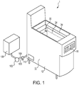
- the container is a vat 20 that is disposed upon a commercial deep fat fryer 10, as shown schematically in FIG. 1 .
- the cooking level detection system is readily utilized with a deep fat fryer where cooking liquid, such as oil, is continuously lost from the vat due to being soaked within the food product being cooked therewithin.
- the instant cooking level detection system provides for an automatic signal that oil level has dropped below a certain level (which can be set by the manufacturer or positioned by the user), which allows for automatic refilling of the oil into the vat, or for an alarm to the kitchen operator that oil needs to be added to the vat.
- the fryer 10 used with the cooking level detection system may be a conventional fryer (shown schematically in FIG. 1 ), with a housing 12 that supports a vat 20.
- the fryer 10 includes a heater 18 (either an electrical or gas burner) to continuously or cyclically provide heat to the cooking liquid Z ( FIGs. 3 , 4, 5 ) disposed within the vat 20.
- the vat 20 may receive a basket (not shown) that holds food product within the heated cooking liquid (such as oil) to cook the food, and then can be removed to easily remove the food product from the cooking liquid.
- the fryer 10 may have a control panel 15 that allows for user inputs to control the cooking functions of the fryer 10.
- the control panel 15 may communicate with a control system 110 (shown schematically in FIG. 1 ), discussed below to automatically or manually operate the fryer 10 for manual or repeated cooking cycles (such as cycle the heater 18 to maintain cooking liquid Z temperature based upon measured liquid temperature or expected temperature).
- the cooking liquid level detection system includes a shell 30 that supports both a temperature sensor 50 and a heat producing element 40.
- the shell 30 is formed to extend within the cooking volume within the vat 20 and fully encloses both the temperature sensor 50 and the heat producing element 40, such that the cooking liquid Z does not come into direct contact with either the temperature sensor 50 or the heat producing element 40.
- the shell 30 may be disposed at or just above the desired minimum operational cooking liquid level 24 within the vat 20, to allow for a determination that cooking liquid Z is not in contact with the shell 30, as calculated by the control system 110, discussed below.
- This position of the shell 30 just above the desired minimum cooking liquid level within the vat 20 provides for an opportunity to add cooking liquid to the vat 20, either through an automated function as directed by the control system 110, discussed below, or through manual action, potentially upon receipt of an audible and/or visual low level alarm initiated by the control system 110.
- the shell 30 may include an insulation block 38 disposed to thermally isolate the heat producing element 40 and the temperature sensor 50 from the ambient through an open end 34 of the shell (where provided).
- Embodiments that include an insulation block 38 are calibrated with the assumption that no heat escapes (or only a certain amount or percentage of heat escapes as understood after experimental testing of the system within a vat 20 with cooking liquid Z) from the open end 34 of the shell 30.
- the insulation block 38 may be formed from one of many conventional materials with relatively low thermal conductivity.
- the shell 30 may not include an insulation layer 38, with the control system 110, discussed below, calibrated based upon the experimentally determined amount of heat escaping the heat producing element 40 through the open end 34 of the shell 30.
- both opposite ends (32, 34) of the shell 30 may be sealed (with or without an insulation block 38 provided proximate to the end (similar to open end 34) extending out of the vat 20.
- the shell 30 may extend into the cooking volume through an aperture in a wall defining the vat 20 and be fixed to the wall defining the vat 20 with one or more fasteners 37 (shown schematically in FIGs. 4-5 ).
- the heat producing element 40 may be disposed in surface-to-surface contact with an inner surface of the shell 30, such that a significant portion of the heat generated by the heat producing element 40, when energized by the control system 110, passes directly to the shell 30 through conduction heat transfer.
- the heat producing element 40 is preferably a resistance heater, which provides a known amount of heat in response to a known amount of current passing therethrough. Generally, the heat produced by a resistance is equivalent to the amount of current (squared) multiplied by the resistance of the heat producing element 40 (I 2 R).
- Other types of known heaters that fit within a small, enclosed shell 30 and can be remotely operated based upon an electrical signal may be used instead of or in conjunction with a resistance heater.
- the heat producing element 40 may be an RTD with a known or calibrated heat output.
- the heat producing element 40 be disposed close to or in contact with the closed distal end 32 of the shell 30, to minimize the amount of heat transferred to the shell 30 that is transferred to the wall defining the vat 20 by conduction rather than to the cooking liquid Z through convection and conduction with the shell 30.
- the heat producing element 40 is electrically connected to the control system 110 with one or more wires 82, which provide a path for current between the control system 110 and the heat producing element 40 to energize the heat producing element 40.
- the type and rating for the heat producing element 40 is selected such that the heat generated by the heat producing element 40 is sufficient to establish a steady state temperature similar to a normal temperature of the liquid disposed within the vat 20.
- the heat producing element 40 may generate a sufficient amount of heat to maintain its temperature around 325-350 degrees F, which is part of or all of the range of normal oil temperatures in a commercial deep fat fryer.
- the temperature sensor 50 is disposed within the shell 30 and in close proximity to one or more surfaces of the heat producing element 40, such that the temperature sensor 50 measures the surface temperature of the heat producing element 40. In some embodiments, the temperature sensor 50 is in contact with a surface of the heat producing element 40.
- the temperature sensor 50 may be an RTD (resistance temperature detector), or other compact electrical temperature detecting device. In some embodiments, the temperature sensor 50 may be of small size in comparison to the heat producing element 40, and the shell 30, such that the heat transfer from the heat producing element 40 to the temperature sensor 50 is small or negligible in comparison to the heat transfer to the shell 30 from the heat producing element 40.
- the temperature sensor 50 is sized and positioned with respect to the heat producing element 40 such that the temperature measured by the temperature sensor 50 is based entirely, or almost entirely, upon the surface temperature of the heat producing element 40, and not based upon the temperature of the shell 30. In some embodiments, all or portions of the outer surface of the temperature sensor 50 not in contact with (or proximate to) the heat producing element 40 may be insulated to minimize the contribution of the sensed temperature by the shell 30 temperature (or ambient temperature within the shell 30).
- the temperature sensor 50 is electrically connected to the control system 110 with one or more wires 84.
- the control system 110 receives a signal from the temperature sensor 50 that is proportional to or representative of the sensed surface temperature of the heat producing element 40.
- the temperature sensor 50 may send a first signal that is proportional to, or representative of, the sensed surface temperature of the heat producing element 40 and a second signal that is proportional to or representative of a rate of change of the first signal (i.e. the rate of change of surface temperature).
- the control system 110 may calculate the rate of change of temperature instead of the temperature sensor 50.
- the control system may also provide operational power to and receive a signal from the temperature sensor 50 proportional to or representative of the surface temperature of the heat producing element 40.
- the heat producing element 40 may receive electrical power for operation from another source, but receive a signal to control the operation of the heat producing element 40 from the control system 110.
- control system 110 follows the steps and performs the determinations depicted in FIG. 6 , while in other embodiments the control system 110 may follow a different routine designed to perform one or more of the steps or functions described herein to use the level detection system disclosed herein.
- the control system 110 deenergizes the heat producing element 40 (step 240).
- a temperature setpoint as stored within a memory source, or in a remote storage location in communication with the control system 110
- the control system 110 deenergizes the heat producing element 40 (step 240).
- the temperature setpoint to secure the heat producing element 40 (“hot setpoint") may be a function of the various design and operational parameters of the fryer, such as oil temperature, ambient temperature, among other factors.
- a temperature within the range of about 330-370 degrees Fahrenheit may be appropriate (inclusive off all temperatures within this range), while in other embodiments, specific values such as 350, 355, 358, 360 degrees Fahrenheit may be appropriate for the hot setpoint. Due to tolerances in the heat output of the heat producing element 40 and the tolerances and calibration of the sensor, this setpoint may vary within a temperature range.
- control system 110 continues to monitor the surface temperature of the heat producing element 40 (step 250) and additionally calculates the magnitude of the rate of change of surface temperature (step 260), or in embodiments where the temperature sensor 50 is capable of calculating this rate of change, receives a signal proportional to or representative of this rate of change of surface temperature.
- the control system 110 continuously compares the magnitude of the rate of change of surface temperature with a reference value, or a reference value range (step 270).
- control system 110 may compare the measured rate of change with a range of possible reference values, instead of a specific reference value due to the range of tolerances of the thermal output of a heat producing element 40, as well as tolerances or calibration of the sensor, which could cause the measured temperature and therefor the calculated rate of change to be affected.
- rate of heat loss and the change in surface temperature is function of the presence of cooking liquid, or the absence of cooking liquid in contact with the outer surface of the shell 30.
- the control system 110 is programmed to conclude that there is cooking liquid present at the level of the shell 30, and the upper surface X ( FIG. 4 ) of the cooking liquid Z is above the shell 30.
- an appropriate reference value range may be a function of various design parameters of the fryer, such as the geometry of the vat, the normal temperature of the cooking fluid, the expected ambient temperature, the normal level of the shell 30 within the vat, among other factors.
- the control system 110 may provide an audible and/or visual alarm (step 290) and may initiate an automatic refill sequence (step 300).
- the fryer 10 and specifically the vat 20 may be fluidly connected to a source of cooking liquid such as in a holding tank 100, which may be either pumped to the vat 20 or allowed to gravity drain to the vat 20.
- the control system 110 may operate a pump 103 that takes suction from the holding tank 100 and directs replacement liquid to the vat 20, and may open one or more isolation valves 105 to allow cooking liquid to refill the vat 20.
- the control system 110 may start the level measurement cycle again (step 210).
- the control system 110 may deenergize the heaters 18 within the vat 20, and reenergize (to return to the normal heating cycle) when liquid level returns to the normal band.
- the system initiates a delay (such as a 3-5 minute delay) which allows the system to thermally stabilize before the heat producing element 40 again performs probe checks (step 215) and energizes the probe again (step 220).
- the control system 110 continues to monitor the surface temperature of the heat producing element 40 (repeating step 250), calculating the rate of change of surface temperature (repeating step 260) and comparing that measured rate of change with the reference value range (step 270), collectively step 310.
- the control system 110 may additionally start a clock with the completion of the first comparison step (270) that continues to run as step 310 continues to be performed. If the rate of change remains outside the reference value range, the monitoring and comparison step (310) may end after a specific time measured by the clock and the system reverts to the probe checks (step 215).
- the system also automatically reverts to the probe checks (step 215).
- the "cool setpoint" for the measured setpoint may be within a range of temperatures, such as between 200 to 275 degrees Fahrenheit (inclusive of all temperatures therewithin). In some embodiments, the cool setpoint may be 245, 250, 255, or 260 degrees Fahrenheit.
Landscapes
- Physics & Mathematics (AREA)
- Thermal Sciences (AREA)
- Fluid Mechanics (AREA)
- General Physics & Mathematics (AREA)
- Engineering & Computer Science (AREA)
- Food Science & Technology (AREA)
- Frying-Pans Or Fryers (AREA)
Description
- This application claims priority from
U.S. Provisional Application No. 61/618,780 filed on March 31, 2012 U.S. Provisional Application No. 61/619,389 filed on April 2, 2012 13/804,124, filed March 14, 2013 - The subject disclosure relates to commercial deep fat fryers where a heated liquid is maintained within a normal band. Conventional level detectors, such as floats and the like are known to have various drawbacks.
- A deep fat fryer with a liquid level detection system is known from
FR2697985 - An embodiment of the disclosure provides a deep fat fryer as defined in claim 1.
- A second embodiment of the disclosure provides a method of controlling a level of liquid within a deep fat fryer as defined in claim 8.
- Advantages of the disclosed system will become more apparent to those skilled in the art from the following description of embodiments that have been shown and described by way of illustration. As will be realized, other and different embodiments are contemplated, and the disclosed details are capable of modification in various respects. Accordingly, the drawings and description are to be regarded as illustrative in nature and not as restrictive.
-
-
FIG. 1 is a perspective schematic view of a fryer using a cooking liquid level detection system. -
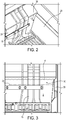
FIG. 2 is a perspective view within a vat of the shell of the level detection system. -
FIG. 3 is a front view of the view ofFIG. 2 . -
FIG. 4 is a side cross-sectional view of the cooking level detector system disposed within a vat showing a liquid level above the shell. -
FIG. 5 is the view ofFIG. 4 showing a liquid level below the shell. -
FIG. 6 is a flowchart showing the operational steps of the control system to control liquid level within the vat. - Turning now to
FIGs. 1-6 , a cooking liquid level detection system 1 is provided. The cooking level detection system 1 includes a liquid level detector that is normally disposed within, or extending into, a container that houses a volume of cooking liquid. The container is avat 20 that is disposed upon a commercialdeep fat fryer 10, as shown schematically inFIG. 1 . As will be readily appreciated by one of ordinary skill in the art upon review of the instant specification and drawings, the cooking level detection system is readily utilized with a deep fat fryer where cooking liquid, such as oil, is continuously lost from the vat due to being soaked within the food product being cooked therewithin. Accordingly, the oil level within the cooking vat of conventional fryers must be periodically manually monitored during periods of heavy use and the kitchen operators must often manually fill the cooking vat with fresh oil. The instant cooking level detection system provides for an automatic signal that oil level has dropped below a certain level (which can be set by the manufacturer or positioned by the user), which allows for automatic refilling of the oil into the vat, or for an alarm to the kitchen operator that oil needs to be added to the vat. - The
fryer 10 used with the cooking level detection system may be a conventional fryer (shown schematically inFIG. 1 ), with ahousing 12 that supports avat 20. Thefryer 10 includes a heater 18 (either an electrical or gas burner) to continuously or cyclically provide heat to the cooking liquid Z (FIGs. 3 ,4, 5 ) disposed within thevat 20. Thevat 20 may receive a basket (not shown) that holds food product within the heated cooking liquid (such as oil) to cook the food, and then can be removed to easily remove the food product from the cooking liquid. Thefryer 10 may have acontrol panel 15 that allows for user inputs to control the cooking functions of thefryer 10. Thecontrol panel 15 may communicate with a control system 110 (shown schematically inFIG. 1 ), discussed below to automatically or manually operate thefryer 10 for manual or repeated cooking cycles (such as cycle theheater 18 to maintain cooking liquid Z temperature based upon measured liquid temperature or expected temperature). - As best shown in
FIGs. 4-5 , the cooking liquid level detection system includes ashell 30 that supports both atemperature sensor 50 and aheat producing element 40. Theshell 30 is formed to extend within the cooking volume within thevat 20 and fully encloses both thetemperature sensor 50 and theheat producing element 40, such that the cooking liquid Z does not come into direct contact with either thetemperature sensor 50 or theheat producing element 40. - In some embodiments, best shown in
FIG. 3 , theshell 30 may be disposed at or just above the desired minimum operationalcooking liquid level 24 within thevat 20, to allow for a determination that cooking liquid Z is not in contact with theshell 30, as calculated by thecontrol system 110, discussed below. This position of theshell 30 just above the desired minimum cooking liquid level within thevat 20 provides for an opportunity to add cooking liquid to thevat 20, either through an automated function as directed by thecontrol system 110, discussed below, or through manual action, potentially upon receipt of an audible and/or visual low level alarm initiated by thecontrol system 110. - In some embodiments, the
shell 30 may include aninsulation block 38 disposed to thermally isolate theheat producing element 40 and thetemperature sensor 50 from the ambient through anopen end 34 of the shell (where provided). Embodiments that include aninsulation block 38 are calibrated with the assumption that no heat escapes (or only a certain amount or percentage of heat escapes as understood after experimental testing of the system within avat 20 with cooking liquid Z) from theopen end 34 of theshell 30. Theinsulation block 38 may be formed from one of many conventional materials with relatively low thermal conductivity. Alternatively, in other embodiments, theshell 30 may not include aninsulation layer 38, with thecontrol system 110, discussed below, calibrated based upon the experimentally determined amount of heat escaping theheat producing element 40 through theopen end 34 of theshell 30. In still other embodiments, both opposite ends (32, 34) of theshell 30 may be sealed (with or without aninsulation block 38 provided proximate to the end (similar to open end 34) extending out of thevat 20. Theshell 30 may extend into the cooking volume through an aperture in a wall defining thevat 20 and be fixed to the wall defining thevat 20 with one or more fasteners 37 (shown schematically inFIGs. 4-5 ). - The
heat producing element 40 may be disposed in surface-to-surface contact with an inner surface of theshell 30, such that a significant portion of the heat generated by theheat producing element 40, when energized by thecontrol system 110, passes directly to theshell 30 through conduction heat transfer. Theheat producing element 40 is preferably a resistance heater, which provides a known amount of heat in response to a known amount of current passing therethrough. Generally, the heat produced by a resistance is equivalent to the amount of current (squared) multiplied by the resistance of the heat producing element 40 (I2R). Other types of known heaters that fit within a small, enclosedshell 30 and can be remotely operated based upon an electrical signal may be used instead of or in conjunction with a resistance heater. In some embodiments, theheat producing element 40 may be an RTD with a known or calibrated heat output. - It is preferable that the
heat producing element 40 be disposed close to or in contact with the closeddistal end 32 of theshell 30, to minimize the amount of heat transferred to theshell 30 that is transferred to the wall defining thevat 20 by conduction rather than to the cooking liquid Z through convection and conduction with theshell 30. One of skill in the art, after a thorough review of this specification, will appreciate the optimal length (or range of lengths) for theshell 30 extending within thevat 20 based upon the desire to minimize heat loss from the shell to thevat 20 through conduction, while also minimizing the distance that theshell 30 extends within the cooking volume to prevent theshell 30 from interfering with the basket position, a basket lift mechanism, a filtering mechanism, an oil removal mechanism, or other components that may be associated with or placed within thevat 20. Theheat producing element 40 is electrically connected to thecontrol system 110 with one ormore wires 82, which provide a path for current between thecontrol system 110 and theheat producing element 40 to energize theheat producing element 40. - The type and rating for the
heat producing element 40 is selected such that the heat generated by theheat producing element 40 is sufficient to establish a steady state temperature similar to a normal temperature of the liquid disposed within thevat 20. By way of example, theheat producing element 40 may generate a sufficient amount of heat to maintain its temperature around 325-350 degrees F, which is part of or all of the range of normal oil temperatures in a commercial deep fat fryer. - The
temperature sensor 50 is disposed within theshell 30 and in close proximity to one or more surfaces of theheat producing element 40, such that thetemperature sensor 50 measures the surface temperature of theheat producing element 40. In some embodiments, thetemperature sensor 50 is in contact with a surface of theheat producing element 40. Thetemperature sensor 50 may be an RTD (resistance temperature detector), or other compact electrical temperature detecting device. In some embodiments, thetemperature sensor 50 may be of small size in comparison to theheat producing element 40, and theshell 30, such that the heat transfer from theheat producing element 40 to thetemperature sensor 50 is small or negligible in comparison to the heat transfer to theshell 30 from theheat producing element 40. Thetemperature sensor 50 is sized and positioned with respect to theheat producing element 40 such that the temperature measured by thetemperature sensor 50 is based entirely, or almost entirely, upon the surface temperature of theheat producing element 40, and not based upon the temperature of theshell 30. In some embodiments, all or portions of the outer surface of thetemperature sensor 50 not in contact with (or proximate to) theheat producing element 40 may be insulated to minimize the contribution of the sensed temperature by theshell 30 temperature (or ambient temperature within the shell 30). - The
temperature sensor 50 is electrically connected to thecontrol system 110 with one ormore wires 84. In some embodiments, thecontrol system 110 receives a signal from thetemperature sensor 50 that is proportional to or representative of the sensed surface temperature of theheat producing element 40. In some embodiments, thetemperature sensor 50 may send a first signal that is proportional to, or representative of, the sensed surface temperature of theheat producing element 40 and a second signal that is proportional to or representative of a rate of change of the first signal (i.e. the rate of change of surface temperature). In other embodiments, thecontrol system 110 may calculate the rate of change of temperature instead of thetemperature sensor 50. - The
control system 110, is shown schematically inFIG. 1 , and may control the operation of the fryer 10 (e.g. the cyclic operation of the heater 18) to maintain a measured oil temperature within a predetermined band, to time and count cooking cycles, etc. and may additionally control the operation of the cooking liquid level detection system. As mentioned above, thecontrol system 110 is in communication with both of the heat producing element 40 (throughelectrical connection 82, shown schematically inFIGs. 4-5 ) and the temperature sensor 50 (throughelectrical connection 84, shown schematically inFIGs. 4-5 ). Thecontrol system 110 selectively provides a signal to energize and deenergize theheat producing element 40 and may also provide electrical power to operate theheat producing element 40. The control system may also provide operational power to and receive a signal from thetemperature sensor 50 proportional to or representative of the surface temperature of theheat producing element 40. Alternatively, in some embodiments theheat producing element 40 may receive electrical power for operation from another source, but receive a signal to control the operation of theheat producing element 40 from thecontrol system 110. - In some embodiments, the
control system 110 follows the steps and performs the determinations depicted inFIG. 6 , while in other embodiments thecontrol system 110 may follow a different routine designed to perform one or more of the steps or functions described herein to use the level detection system disclosed herein. - Initially, or at the start of a new monitoring cycle, the
control system 110 may initialize itself (step 210) and may perform one or more operational self-checks (such as power available, signal available, open or shortedtemperature sensor 50 detection, etc.) (step 215). Next, instep 220 thecontrol system 110 energizes theheat producing element 40 located within theshell 30, while measuring the sensed surface temperature of theheat producing element 40 as received by the temperature signal from the temperature sensor 50 (step 230). When the surface temperature of theheat producing element 40 reaches either a temperature setpoint (as stored within a memory source, or in a remote storage location in communication with the control system 110), such as a temperature setpoint close to or within the normal cooking liquid temperature range (generally 325-350 F), or when the heating sequence has reached a set time duration, thecontrol system 110 deenergizes the heat producing element 40 (step 240). As will be understood, the temperature setpoint to secure the heat producing element 40 ("hot setpoint") may be a function of the various design and operational parameters of the fryer, such as oil temperature, ambient temperature, among other factors. In one specific embodiment, a temperature within the range of about 330-370 degrees Fahrenheit may be appropriate (inclusive off all temperatures within this range), while in other embodiments, specific values such as 350, 355, 358, 360 degrees Fahrenheit may be appropriate for the hot setpoint. Due to tolerances in the heat output of theheat producing element 40 and the tolerances and calibration of the sensor, this setpoint may vary within a temperature range. - After the
heat producing element 40 is deenergized, thecontrol system 110 continues to monitor the surface temperature of the heat producing element 40 (step 250) and additionally calculates the magnitude of the rate of change of surface temperature (step 260), or in embodiments where thetemperature sensor 50 is capable of calculating this rate of change, receives a signal proportional to or representative of this rate of change of surface temperature. Thecontrol system 110 continuously compares the magnitude of the rate of change of surface temperature with a reference value, or a reference value range (step 270). In some embodiments, thecontrol system 110 may compare the measured rate of change with a range of possible reference values, instead of a specific reference value due to the range of tolerances of the thermal output of aheat producing element 40, as well as tolerances or calibration of the sensor, which could cause the measured temperature and therefor the calculated rate of change to be affected. As can be understood, because theheat producing element 40 and theshell 30 are configured for efficient heat transfer therebetween, and rate of heat loss and the change in surface temperature (either due to heat loss from theshell 30 andheat producing element 40, or potential heat gain from the relatively hotter oil) is function of the presence of cooking liquid, or the absence of cooking liquid in contact with the outer surface of theshell 30. Because theheat producing element 40 was originally heated to a temperature close to the normal temperature cooking liquid, there will only be a small amount of heat flow through the shell when theheat producing element 40 is deenergized when the hot cooking liquid is in contact with theshell 30. This results in a very small rate of change in the surface temperature of theheat producing element 40, and therefore thecontrol system 110 is programmed to conclude that there is cooking liquid present at the level of theshell 30, and the upper surface X (FIG. 4 ) of the cooking liquid Z is above theshell 30. - In contrast, when there is no hot cooking liquid proximate to, or, in contact with the
shell 30, theshell 30 contacts the ambient air that is at room temperature (or at an increased temperature, but significantly less than oil temperature). In this situation there is a large heat flux from theshell 30 to the ambient (due to the difference in temperature therebetween), and therefore a large heat flux from theheat producing element 40 to theshell 30 and ultimately to the ambient. This large heat flux causes the surface temperature of theheat producing element 40 to decrease rapidly, causing thetemperature sensor 50 to sense a large magnitude of the rate of change of surface temperature (step 260). When the magnitude of the rate of change of surface temperature is within a reference value range that is indicative of a significant heat loss from theheat producing element 40 and shell 30 (either programmed into thecontrol system 110 or in communication with the control system 110) thecontrol system 110 makes the determination that the cooking liquid is not in contact with the shell 30 (step 280), and the upper surface X is below the shell 30 (FIG. 5 ). As will be appreciated by one of ordinary skill in the art with reference to this disclosure, an appropriate reference value range may be a function of various design parameters of the fryer, such as the geometry of the vat, the normal temperature of the cooking fluid, the expected ambient temperature, the normal level of theshell 30 within the vat, among other factors. - Accordingly, because the system identifies a low cooking liquid condition, the
control system 110 may provide an audible and/or visual alarm (step 290) and may initiate an automatic refill sequence (step 300). As shown schematically inFIG. 1 , thefryer 10 and specifically thevat 20 may be fluidly connected to a source of cooking liquid such as in aholding tank 100, which may be either pumped to thevat 20 or allowed to gravity drain to thevat 20. In situations where thecontrol system 110 automatically directs replacement cooking liquid to thevat 20, thecontrol system 110 may operate apump 103 that takes suction from theholding tank 100 and directs replacement liquid to thevat 20, and may open one ormore isolation valves 105 to allow cooking liquid to refill thevat 20. Upon completion of the cooking liquid refill cycle (as measured by one or more of elapsed time, change in level of theholding tank 100, or by other parameters), thecontrol system 110 may start the level measurement cycle again (step 210). In some embodiments, upon a determination that the liquid level X is below theshell 30, thecontrol system 110 may deenergize theheaters 18 within thevat 20, and reenergize (to return to the normal heating cycle) when liquid level returns to the normal band. In some embodiments, after theliquid refill cycle 300, the system initiates a delay (such as a 3-5 minute delay) which allows the system to thermally stabilize before theheat producing element 40 again performs probe checks (step 215) and energizes the probe again (step 220). - Alternatively, in situations where the calculated rate of change is outside the reference value range (with a lower magnitude than the reference value range), the
control system 110 continues to monitor the surface temperature of the heat producing element 40 (repeating step 250), calculating the rate of change of surface temperature (repeating step 260) and comparing that measured rate of change with the reference value range (step 270), collectively step 310. Thecontrol system 110 may additionally start a clock with the completion of the first comparison step (270) that continues to run asstep 310 continues to be performed. If the rate of change remains outside the reference value range, the monitoring and comparison step (310) may end after a specific time measured by the clock and the system reverts to the probe checks (step 215). If the surface temperature decreases to a low temperature setpoint of theheat producing element 40, the system also automatically reverts to the probe checks (step 215). Similar to the hot setpoint referenced above, the "cool setpoint" for the measured setpoint may be within a range of temperatures, such as between 200 to 275 degrees Fahrenheit (inclusive of all temperatures therewithin). In some embodiments, the cool setpoint may be 245, 250, 255, or 260 degrees Fahrenheit. - While the preferred embodiments have been described, it should be understood that the invention is not so limited and modifications may be made without departing from the invention. The scope of the invention is defined by the appended claims.
Claims (8)
- A deep fat fryer, comprising:a vat for holding a volume of cooking liquid, the vat in thermal communication with a heat source and configured to heat the cooking liquid disposed within the vat to a normal cooking temperature within a cooking temperature range; anda level detection system comprising a control system and a detector, the detector being disposed within the vat to monitor a level of the cooking liquid within the vat, the detector comprising:a temperature sensor;a heat producing element proximate to the temperature sensor; anda shell disposed around the temperature sensor and heat producing element, the shell being disposed within the vat to provide a barrier between the cooking liquid disposed within the vat and each of the temperature sensor and heat producing element,wherein the heat producing element is configured to transfer heat generated therein to the shell, and the temperature sensor is configured to measure a surface temperature of the heat producing element;the control system being in communication with the temperature sensor and the heat producing element;characterised in that the control system is configured to:energise the heat producing element to generate a flux of heat to heat the heat producing element to a hot setpoint temperature; and thende-energise the heat producing element; and thendetermine the presence or absence of cooking liquid proximate to the detector by comparing a rate of change of the measured surface temperature of the de-energised heat producing element with a reference value range;and the heat producing element and the shell are configured such that heat loss from the shell and the heat producing element is larger when the shell is not in contact with the cooking liquid than when the shell is in contact with the cooking liquid at the normal cooking temperature,and the hot setpoint temperature is close to or within the cooking temperature range,and the control system is further configured to determine a presence of cooking liquid proximate the detector when the rate of change is lower than the reference value range, and an absence of cooking liquid proximate the detector when the rate of change is within the reference value range.
- The fryer of claim 1, wherein the heat producing element makes surface contact with the shell to allow for conductive heat transfer therebetween.
- The fryer of claim 1 or claim 2, wherein the temperature sensor is configured to measure or calculate the rate of change of the surface temperature of the heat producing element.
- The fryer of claim 1, wherein the temperature sensor is arranged in thermal contact with the heat producing element.
- The fryer of any claim 1 or claim 2, wherein the control system is configured to monitor a first output signal from the temperature sensor representative of the measured surface temperature of the heat producing element, and measure or calculate the rate of change of the surface temperature of the heat producing element based on the first output signal.
- The fryer of claim 1, wherein the control system is operatively connected with a pump and the vat is fluidly connected with the pump, wherein the control system is configured to selectively provide a second signal to operate the pump to urge cooking liquid to flow to the vat to increase the volume of cooking liquid within the vat.
- The fryer of claim 6, wherein after operating the pump the control system is arranged to initiate a delay before re-energising the heat producing element.
- A method of controlling a level of cooking liquid within the deep fat fryer of claim 5, comprising:heating the cooking liquid disposed within the vat to the normal cooking temperature;energizing the heat producing element to heat the heat producing element to the hot setpoint temperature;deenergizing the heat producing element after the first output signal reaches either a predetermined value or a substantially steady state value;measuring the rate of change of the first output signal after the heat producing element is deenergized;comparing the measured rate of change of the first output signal with the reference value range; anddetermining the presence or absence of liquid proximate to the liquid level detector based upon the comparison between the measured rate of change of the first output signal and the reference value range,wherein the presence of cooking liquid proximate the detector is determined when the rate of change is lower than the reference value range, and the absence of cooking liquid proximate the detector is determined when the rate of change is within the reference value range.
Applications Claiming Priority (4)
| Application Number | Priority Date | Filing Date | Title |
|---|---|---|---|
| US201261618780P | 2012-03-31 | 2012-03-31 | |
| US201261619389P | 2012-04-02 | 2012-04-02 | |
| US13/804,124 US9357881B2 (en) | 2012-03-31 | 2013-03-14 | Oil level detection system for deep fat fryer |
| PCT/US2013/033069 WO2013148425A2 (en) | 2012-03-31 | 2013-03-20 | Oil level detection system for deep fat fryer |
Publications (4)
| Publication Number | Publication Date |
|---|---|
| EP2831552A2 EP2831552A2 (en) | 2015-02-04 |
| EP2831552A4 EP2831552A4 (en) | 2015-10-28 |
| EP2831552B1 true EP2831552B1 (en) | 2018-10-24 |
| EP2831552B8 EP2831552B8 (en) | 2019-01-02 |
Family
ID=49261386
Family Applications (1)
| Application Number | Title | Priority Date | Filing Date |
|---|---|---|---|
| EP13770122.3A Active EP2831552B8 (en) | 2012-03-31 | 2013-03-20 | Oil level detection system for deep fat fryer |
Country Status (8)
| Country | Link |
|---|---|
| US (2) | US9357881B2 (en) |
| EP (1) | EP2831552B8 (en) |
| AU (1) | AU2013240104B2 (en) |
| BR (1) | BR112014024446B1 (en) |
| CA (1) | CA2868790C (en) |
| ES (1) | ES2698507T3 (en) |
| MX (1) | MX343051B (en) |
| WO (1) | WO2013148425A2 (en) |
Families Citing this family (26)
| Publication number | Priority date | Publication date | Assignee | Title |
|---|---|---|---|---|
| US9357881B2 (en) | 2012-03-31 | 2016-06-07 | Pitco Frialator, Inc. | Oil level detection system for deep fat fryer |
| EP3119250B1 (en) | 2014-03-18 | 2018-06-06 | Koninklijke Philips N.V. | Apparatus for preparing food having an improved thermal protection |
| US10085584B2 (en) * | 2014-06-09 | 2018-10-02 | Whirlpool Corporation | Method of regulating temperature for sous vide cooking and apparatus therefor |
| JP6212467B2 (en) * | 2014-11-13 | 2017-10-11 | 株式会社フジキン | Liquid level gauge and liquid raw material vaporizer |
| DE102015101299A1 (en) * | 2015-01-29 | 2016-08-04 | Vorwerk & Co. Interholding Gmbh | Electric kitchen appliance |
| US10736463B2 (en) * | 2016-03-17 | 2020-08-11 | Henny Penny Corporation | Multiport/rotary valve sensor using hall effect control |
| CN107202620A (en) * | 2016-03-18 | 2017-09-26 | 徕卡显微系统(上海)有限公司 | Liquid level sensor, control method thereof, and reactor having same |
| WO2017184143A1 (en) * | 2016-04-21 | 2017-10-26 | Hewlett-Packard Development Company, L.P. | Over-molded fluid level sensor and method of forming the same |
| WO2017189010A1 (en) * | 2016-04-29 | 2017-11-02 | Hewlett-Packard Development Company, L.P. | Detecting fluid levels using a voltage comparator |
| WO2019178431A1 (en) | 2018-03-16 | 2019-09-19 | Pitco Frialator, Inc. | Fluid top-off detection and control system |
| US10634541B2 (en) * | 2018-03-20 | 2020-04-28 | Haier Us Appliance Solutions, Inc. | Methods for safe operation of a cooktop appliance |
| PL3781912T3 (en) * | 2018-04-18 | 2024-04-22 | Pitco Frialator, Inc. | Capacitive sensor device |
| US12207764B2 (en) * | 2018-08-06 | 2025-01-28 | Paloma Rheem Holdings Co., Ltd. | Fryer |
| PT3681723T (en) | 2018-12-03 | 2021-08-27 | Hewlett Packard Development Co | Logic circuitry |
| US11338586B2 (en) | 2018-12-03 | 2022-05-24 | Hewlett-Packard Development Company, L.P. | Logic circuitry |
| BR112021010672A2 (en) | 2018-12-03 | 2021-08-24 | Hewlett-Packard Development Company, L.P. | logic circuits |
| EP3695334A1 (en) | 2018-12-03 | 2020-08-19 | Hewlett Packard Enterprise Development Company LP | Logic circuitry |
| CN113165395B (en) | 2018-12-03 | 2023-01-10 | 惠普发展公司,有限责任合伙企业 | logic circuit system |
| US10894423B2 (en) | 2018-12-03 | 2021-01-19 | Hewlett-Packard Development Company, L.P. | Logic circuitry |
| EP3688645A1 (en) | 2018-12-03 | 2020-08-05 | Hewlett-Packard Development Company, L.P. | Logic circuitry package |
| CA3121146C (en) | 2018-12-03 | 2024-05-28 | Hewlett-Packard Development Company, L.P. | Logic circuitry package for controlling ic2 traffic |
| CN113168453A (en) | 2018-12-03 | 2021-07-23 | 惠普发展公司,有限责任合伙企业 | Logic circuitry packaging |
| PL3682359T3 (en) | 2018-12-03 | 2021-05-17 | Hewlett-Packard Development Company, L.P. | Logic circuitry |
| US11407229B2 (en) | 2019-10-25 | 2022-08-09 | Hewlett-Packard Development Company, L.P. | Logic circuitry package |
| WO2021221678A1 (en) | 2020-04-30 | 2021-11-04 | Hewlett-Packard Development Company, L.P. | Logic circuitry package for print apparatus |
| US12075945B1 (en) * | 2022-12-07 | 2024-09-03 | Sidney Tracy Highnote | High speed convection fryer |
Family Cites Families (120)
| Publication number | Priority date | Publication date | Assignee | Title |
|---|---|---|---|---|
| US2578129A (en) | 1949-08-31 | 1951-12-11 | Daugherty Thomas | Cooking oil filtering apparatus |
| US2698092A (en) | 1951-10-24 | 1954-12-28 | Frysweet Filter Corp | Apparatus for filtering frying fat |
| US2686250A (en) | 1951-11-02 | 1954-08-10 | Gen Electric | Electric heating apparatus |
| NL136135C (en) | 1961-05-05 | |||
| US3410199A (en) | 1967-02-02 | 1968-11-12 | Food Res & Equipment Company | Deep fat fryer with automatic filtration and storage means |
| US3466997A (en) | 1967-03-08 | 1969-09-16 | Kentucky Fried Chicken Co | Chicken frying equipment |
| US3648595A (en) | 1970-04-22 | 1972-03-14 | Restaurant Products Inc | Food fryer with continuously filtered cooking oil |
| US3797378A (en) | 1970-04-22 | 1974-03-19 | W Morris | Food fryer with continuously filtered cooking oil |
| US3667373A (en) | 1970-06-08 | 1972-06-06 | Frederic A Sicher | Automatic machine for vending fried foods |
| US3701313A (en) | 1971-02-12 | 1972-10-31 | Food Research & Equipment Co | Deep fat fryer unit with solenoid valves and automatic controls |
| US3809062A (en) | 1972-02-04 | 1974-05-07 | Frymaster Corp | Cooking system |
| US3894482A (en) | 1972-05-15 | 1975-07-15 | John R Murphy | Cooking oil filtering |
| US4050447A (en) | 1976-05-24 | 1977-09-27 | Andrew Terracciano | Deep fat fryer heated fat supply reservoir and fat replenishment device |
| US4324173A (en) | 1976-12-23 | 1982-04-13 | The Frymaster Corporation | Filter system for frying apparatus |
| US4503320A (en) * | 1978-05-19 | 1985-03-05 | Polster Louis S | Deep fat cooking temperature control system |
| US4273991A (en) | 1979-11-29 | 1981-06-16 | B & W Metals Company, Inc. | Pressure cooker |
| US4672540A (en) | 1981-05-15 | 1987-06-09 | The Frymaster Corporation | Intelligent cooking appliance |
| US4858119A (en) | 1981-05-15 | 1989-08-15 | The Frymaster Corporation | Intelligent cooking appliance |
| US4437159A (en) | 1981-05-15 | 1984-03-13 | The Frymaster Corporation | Cooking computer |
| JPS58501393A (en) | 1981-08-27 | 1983-08-18 | キヤタピラ− トラクタ− コンパニ− | Liquid level and temperature sensor |
| JPS58136321A (en) | 1982-02-09 | 1983-08-13 | 三洋電機株式会社 | Microwave fryer apparatus |
| US4489647A (en) | 1982-04-29 | 1984-12-25 | Stamps Kenneth H | Food frying and dispensing apparatus |
| US4478140A (en) | 1982-08-02 | 1984-10-23 | Bullock Robert F | Fryer with oil circulation and conveyor |
| US4457947A (en) | 1983-02-07 | 1984-07-03 | Ui Group, Inc. | Automatic cooking method |
| US4489646A (en) | 1983-02-07 | 1984-12-25 | Ui Group, Inc. | Automatic french frying machine |
| US4502373A (en) | 1983-03-25 | 1985-03-05 | Keating Richard T | Cleaning system for deep fryer |
| US4488478A (en) | 1983-07-08 | 1984-12-18 | J. C. Pitman Company, Inc. | Continuous fryer for potato chips and other snack foods |
| US4487691A (en) | 1984-01-09 | 1984-12-11 | Thermo Electron Corporation | Deep fat fryer with swivel filter element |
| US4623544A (en) | 1984-08-03 | 1986-11-18 | Highnote Sidney T | Constant temperature fryer/cooker assembly |
| DE3527868A1 (en) | 1985-08-02 | 1987-02-12 | Schmidt Feintechnik Gmbh | METHOD AND MEASURING PROBE FOR PROBING THE LEVEL OF THE MASS CURRENT, THE FLUID TYPE, THE FLUID COMPOSITION OR THE LIKE IN A CONTAINER, PIPE OR THE LIKE CONTAINING ONE OR MORE FLUIDS |
| US4599990A (en) | 1985-08-08 | 1986-07-15 | Hobart Corporation | Control system and method for recirculating-type deep fat fryer |
| DE3603539A1 (en) | 1986-02-05 | 1987-08-06 | Merckens J G Gmbh & Co Kg | Device for detecting a liquid level |
| US4722267A (en) | 1986-03-24 | 1988-02-02 | Longin Galockin | French fry vending machine |
| US4798939A (en) | 1986-04-02 | 1989-01-17 | Gallina Corporation | Pressurized liquid cooker with integrated radiant heating apparatus |
| US4768426A (en) | 1986-04-02 | 1988-09-06 | Gallina Corporation | Oil filter apparatus and method for deep oil pressure cooking apparatus |
| US4748902A (en) | 1987-01-21 | 1988-06-07 | Vito Maurantonio | Automatic food cooker and dispenser |
| DE3742783C2 (en) | 1987-12-17 | 1994-07-21 | Hella Kg Hueck & Co | Device for measuring the liquid level in containers, in particular the oil level in internal combustion engines of motor vehicles |
| US4826590A (en) | 1987-12-21 | 1989-05-02 | Filter Systems, Inc. | Cooking oil filtering system |
| US4945893A (en) | 1988-05-13 | 1990-08-07 | Welbilt Corporation | Fryer filtration system |
| US5272961A (en) | 1988-10-17 | 1993-12-28 | The R/M Trust Company | Apparatus for providing french fried potatoes |
| DD278057A1 (en) * | 1988-12-19 | 1990-04-25 | Konsum Rationalisierungs Zentr | SENSOR FOR LEVEL CONTROL OF LIQUID CONTAINERS, ESPECIALLY SAUSAGE BOILING BOILERS |
| US4877386A (en) | 1988-12-20 | 1989-10-31 | J.M. Huber Corporation | Automated sucker rod cleaning apparatus |
| JPH02234032A (en) | 1989-03-08 | 1990-09-17 | Snow Brand Milk Prod Co Ltd | Measuring sensor for detecting fluid state and measuring method by use of sensor |
| US5069116A (en) | 1989-10-24 | 1991-12-03 | Hot Snacks, Inc. | Apparatus for frying foods |
| US5052288A (en) | 1989-10-24 | 1991-10-01 | Hot Snacks, Inc. | Apparatus for dispensing snack foods |
| US5033368A (en) | 1990-03-16 | 1991-07-23 | Henny Penny Corporation | Large capacity gas fired pressure cooker |
| EP0462354B1 (en) | 1990-05-21 | 1996-04-17 | Marc Mareels | Cooking installation for deep-frozen pre-cooked french fries |
| US5234527A (en) | 1990-07-20 | 1993-08-10 | Tokyo Electron Limited | Liquid level detecting device and a processing apparatus |
| CA2036134A1 (en) | 1991-02-12 | 1992-08-13 | Alexander T. Rozak | Self venting automatic food frying and dispensing apparatus |
| US5329343A (en) * | 1991-05-14 | 1994-07-12 | Fuji Xerox Co., Ltd. | Temperature control method and fixing apparatus |
| JP3063224B2 (en) | 1991-05-17 | 2000-07-12 | 松下電器産業株式会社 | Cooking device |
| US5174153A (en) | 1992-03-27 | 1992-12-29 | Kurita Water Industries Ltd. | Device for detecting the level of a liquid in a receptacle |
| DE4232043A1 (en) | 1992-09-24 | 1994-03-31 | Siemens Ag | Process and appts. for continuous monitoring of fluid level - within a container such as the coolant level within a nuclear reactor |
| FR2697985B1 (en) | 1992-11-13 | 1995-02-03 | Thirode Grandes Cuisines Poligny | Method and device for controlling the level of a frying bath and apparatus therefor. |
| US5249511A (en) | 1993-02-09 | 1993-10-05 | Shumate Eldridge J | Bulk cooking oil distribution and waste removal system |
| US5490449A (en) | 1993-02-16 | 1996-02-13 | The Frymaster Corporation | Temperature controller for cooking appliance |
| US5263406A (en) | 1993-03-02 | 1993-11-23 | Chiu Yao Jui | Vacuum type food frying apparatus |
| US5445062A (en) | 1993-05-21 | 1995-08-29 | Polster; Louis S. | Cooker/rethermalizer |
| US5586486A (en) | 1994-02-01 | 1996-12-24 | Vend-It Corporation | Automated deep fryer |
| US5568765A (en) | 1994-09-28 | 1996-10-29 | Sharp Kabushiki Kaisha | Microwave fryer |
| US5730026A (en) | 1995-03-31 | 1998-03-24 | Josef Maatuk | Microprocessor-based liquid sensor and ice detector |
| FR2733586B1 (en) | 1995-04-28 | 1997-07-18 | Cohen Sauveur | AUTOMATIC OIL LEVEL DETECTOR |
| US5617777A (en) | 1995-06-01 | 1997-04-08 | The Frymaster Corporation | Deep fat frying apparatus with automated oil management |
| US5629039A (en) | 1995-06-08 | 1997-05-13 | Ventura Foods, Llc | Cooking oil extending process |
| FR2740537B1 (en) | 1995-10-31 | 1998-01-16 | Seb Sa | STEAM GENERATOR WITH AUTOMATIC SUPPLY AND METHOD FOR MEASURING THE LIQUID LEVEL IN SUCH A GENERATOR |
| US5597601A (en) | 1996-02-29 | 1997-01-28 | Purifry, Llc | Cooking oil filtering apparatus and process employing cylindrical sintered metal filters |
| US5758569A (en) | 1996-03-28 | 1998-06-02 | Barbour International | Poultry frying apparatus |
| US5973297A (en) | 1996-03-28 | 1999-10-26 | Henny Penny Corporation | Apparatus and method for heat regulation of deep fat fryer |
| KR0162475B1 (en) * | 1996-06-12 | 1998-11-16 | 구자홍 | Automatic frying method of frying machine |
| US5759601A (en) | 1996-06-14 | 1998-06-02 | Kovacs; Laszlo | Process for preparing fried potato product from dehydrated potato |
| US6095037A (en) | 1996-09-27 | 2000-08-01 | Pitco Frialator, Inc. | High efficient convection fryer with continuous filtration |
| KR100186438B1 (en) | 1996-10-01 | 1999-03-20 | 구자홍 | Electric fryer and its control method |
| US5827556A (en) * | 1996-10-23 | 1998-10-27 | Tridelta Industries, Inc. | Electronic controller for heating apparatus |
| KR19980025392U (en) * | 1996-11-02 | 1998-08-05 | 유영국 | Food waste dehydrator for washing dishes |
| US5706717A (en) | 1996-11-12 | 1998-01-13 | America's Favorite Chicken Co. | Heating control system for a gas fryer |
| US5870945A (en) | 1997-01-17 | 1999-02-16 | Bivens; Thomas H. | Portable filtration and treatment apparatus |
| US5812060A (en) | 1997-05-01 | 1998-09-22 | Darling International, Inc. | Automated waste cooking grease recycling tank |
| US6057772A (en) | 1997-11-13 | 2000-05-02 | Henny Penny Corporation | Apparatus and method for optically sensing liquid level in cooking vessels |
| US5942269A (en) | 1997-12-19 | 1999-08-24 | Henny Penny Corporation | Method for manipulating cooking medium during cooking operations |
| JPH11237356A (en) | 1998-02-19 | 1999-08-31 | Mitsui Mining & Smelting Co Ltd | Fluid identification method and fluid identification device |
| US6254790B1 (en) | 1998-04-21 | 2001-07-03 | Henny Penny Corporation | Method for filtering suspended materials from cooking substances |
| US6063421A (en) | 1998-07-15 | 2000-05-16 | Barravecchio; Joseph | Method and apparatus for rethermalizing pre-cooked food portions |
| US6783685B2 (en) | 1999-01-19 | 2004-08-31 | Fmc Technologies, Inc. | Oil treatment system |
| US6948364B2 (en) * | 1999-08-03 | 2005-09-27 | Charles Snelling | Apparatus for detecting the internal liquid level in a vessel |
| US6568263B1 (en) * | 1999-08-03 | 2003-05-27 | Charles Darwin Snelling | Liquid level detector and system |
| CA2279957A1 (en) | 1999-08-09 | 2001-02-09 | Speed Fry Corporation | Apparatus and method for automatically frying foodstuff |
| US6202543B1 (en) | 1999-09-21 | 2001-03-20 | Claude Laval Corporation | Removal of particulates from frying oils |
| US6777009B1 (en) | 1999-09-29 | 2004-08-17 | Cfa Properties, Inc. | Cooking appliance and method of use |
| JP2002081573A (en) | 2000-09-07 | 2002-03-22 | Paloma Ind Ltd | Valve opening and closing device for flyer |
| AU2001288903A1 (en) | 2000-09-07 | 2002-03-22 | Hdn Development Corporation | System and process for continuously filtering shortening, oil and the like |
| JP2002125865A (en) | 2000-10-24 | 2002-05-08 | Paloma Ind Ltd | Fryer |
| US7309422B2 (en) | 2001-01-12 | 2007-12-18 | Illinois Tool Works Inc. | Fryer filtration arrangement |
| GB2405224B (en) | 2001-01-30 | 2005-05-25 | Aqualisa Products Ltd | Water mixing valve apparatus |
| KR100387739B1 (en) | 2001-03-07 | 2003-06-18 | 송영주 | A fryer |
| WO2002098266A1 (en) | 2001-05-31 | 2002-12-12 | The Nisshin Oillio, Ltd. | Method of frying and frying device |
| US7100497B2 (en) | 2001-09-12 | 2006-09-05 | Pitco Frialator, Inc. | High temperature, oil saving, rapid cook fryer system |
| EP1427296B1 (en) | 2001-09-21 | 2007-02-21 | The Frymaster Corporation | Frying apparatus with closed loop combustion control and method |
| US6869633B2 (en) | 2002-04-22 | 2005-03-22 | Restaurant Technology, Inc. | Automated food frying device and method |
| JP4021263B2 (en) | 2002-07-09 | 2007-12-12 | パロマ工業株式会社 | Flyer |
| JP2004081430A (en) | 2002-08-26 | 2004-03-18 | Paloma Ind Ltd | Fryer |
| JP2004081431A (en) | 2002-08-26 | 2004-03-18 | Paloma Ind Ltd | Fryer |
| US7322278B2 (en) | 2002-12-11 | 2008-01-29 | Henny Penny Corporation | Fryers which deactivate before a level of a cooking medium falls below a minimum level, and methods of deactivating such fryers |
| JP4176490B2 (en) | 2003-01-16 | 2008-11-05 | パロマ工業株式会社 | Pressure fryer |
| CA2461120A1 (en) | 2003-03-14 | 2004-09-14 | The Vollrath Company, L.L.C. | Food server fluid level control |
| US7015429B2 (en) | 2004-03-08 | 2006-03-21 | Eastern Sources Housewares (Hong Kong) Limited | Deep fryer |
| US20050284823A1 (en) | 2004-06-23 | 2005-12-29 | Fall Ronald E | Cooking oil filter element and method |
| US7015433B2 (en) | 2004-07-14 | 2006-03-21 | Technology Licensing Corporation | Temperature calibration method for a cooking appliance |
| GB0419102D0 (en) | 2004-08-27 | 2004-09-29 | Smiths Group Plc | Fluid-level sensing and fluid detection |
| WO2006065564A2 (en) | 2004-12-17 | 2006-06-22 | The Frymaster Corporation, L.L.C. | Multiple fryer types in unitary cabinet |
| US20080121578A1 (en) | 2006-11-27 | 2008-05-29 | Henny Penny Corporation | Automatic cooking medium filtering systems and methods |
| US8689679B2 (en) | 2006-11-27 | 2014-04-08 | Henny Penny Corporation | Automatic cooking medium level control systems and methods |
| US20080213446A1 (en) | 2007-03-01 | 2008-09-04 | Feinberg Bruce G | Automated fryer refilling device and method |
| US8627763B2 (en) | 2007-03-19 | 2014-01-14 | Frymaster L.L.C. | Automatic top-off for deep fat fryers |
| US7874724B2 (en) | 2007-04-11 | 2011-01-25 | Trane International Inc. | Method for sensing the liquid level in a compressor |
| WO2008144290A2 (en) | 2007-05-15 | 2008-11-27 | Pitco Frialator, Inc. | Continuously operating filtering apparatus |
| US20090039004A1 (en) | 2007-08-07 | 2009-02-12 | Bill Andersen Consulting Llc | Automatic oil filtration and treatment with level control and system heating during filtration |
| EP2037233A1 (en) | 2007-09-14 | 2009-03-18 | General Electric Company | Fluid detector |
| US20090084273A1 (en) | 2007-09-27 | 2009-04-02 | The Frymaster Corporation Llc | Low oil volume fryer with automatic filtration and top-off capability |
| US8438919B2 (en) * | 2010-07-23 | 2013-05-14 | Rosemount Aerospace Inc. | Systems and methods for liquid level sensing having a differentiating output |
| US9357881B2 (en) | 2012-03-31 | 2016-06-07 | Pitco Frialator, Inc. | Oil level detection system for deep fat fryer |
-
2013
- 2013-03-14 US US13/804,124 patent/US9357881B2/en active Active
- 2013-03-20 WO PCT/US2013/033069 patent/WO2013148425A2/en not_active Ceased
- 2013-03-20 BR BR112014024446-4A patent/BR112014024446B1/en active IP Right Grant
- 2013-03-20 AU AU2013240104A patent/AU2013240104B2/en active Active
- 2013-03-20 MX MX2014011832A patent/MX343051B/en active IP Right Grant
- 2013-03-20 ES ES13770122T patent/ES2698507T3/en active Active
- 2013-03-20 EP EP13770122.3A patent/EP2831552B8/en active Active
- 2013-03-20 CA CA2868790A patent/CA2868790C/en active Active
-
2016
- 2016-06-03 US US15/172,345 patent/US10390658B2/en active Active
Non-Patent Citations (1)
| Title |
|---|
| None * |
Also Published As
| Publication number | Publication date |
|---|---|
| BR112014024446B1 (en) | 2020-11-17 |
| MX343051B (en) | 2016-10-21 |
| US20130295245A1 (en) | 2013-11-07 |
| AU2013240104B2 (en) | 2016-10-13 |
| WO2013148425A3 (en) | 2013-11-28 |
| US9357881B2 (en) | 2016-06-07 |
| US10390658B2 (en) | 2019-08-27 |
| ES2698507T3 (en) | 2019-02-05 |
| WO2013148425A2 (en) | 2013-10-03 |
| BR112014024446A2 (en) | 2018-04-10 |
| US20160270595A1 (en) | 2016-09-22 |
| EP2831552A2 (en) | 2015-02-04 |
| CA2868790C (en) | 2017-07-25 |
| MX2014011832A (en) | 2015-04-08 |
| EP2831552B8 (en) | 2019-01-02 |
| AU2013240104A1 (en) | 2014-10-09 |
| EP2831552A4 (en) | 2015-10-28 |
| CA2868790A1 (en) | 2013-10-03 |
Similar Documents
| Publication | Publication Date | Title |
|---|---|---|
| US10390658B2 (en) | Oil level detection system for deep fat fryer | |
| EP2885583B2 (en) | Cooktop with a device for fire mitigation and corresponding method | |
| US20200015624A1 (en) | Method for Cooking Foods, and Apparatus Implementing the Method | |
| EP3152633B1 (en) | Method of predicting the core temperture of a food item during cooking, cooking device and cooking method | |
| EP2388564A1 (en) | Estimating temperature | |
| JP5096553B2 (en) | Automatic filling for fryer | |
| US11739948B2 (en) | Automatic oven with humidity sensor | |
| EP2939497B1 (en) | Apparatus and method for determining core temperature of food | |
| US20080121115A1 (en) | Automatic cooking medium level control systems and methods | |
| JP3920155B2 (en) | Flyer | |
| EP1537808B1 (en) | Coffee maker and microwave oven and method for controlling the same | |
| US20130156902A1 (en) | Cooking medium level monitoring systems, methods, and fryer apparatus | |
| CA3010966C (en) | A glass-ceramic cooking apparatus and a method relating to temperature limiting control for preventing cooking oil ignition | |
| CN112294101A (en) | Cooking equipment, steam valve detection method and device thereof, and storage medium | |
| TR201807447T4 (en) | A cooking device with a water tank. | |
| US20200245814A1 (en) | High limit rtd holder block | |
| JP2004008253A (en) | Fryer | |
| CN105805791B (en) | High frequency heating device | |
| KR100864098B1 (en) | Fire detection control method of microwave oven | |
| WO2019178431A1 (en) | Fluid top-off detection and control system | |
| JPH0584127A (en) | Rice cooker | |
| CN116831441A (en) | Heating base and cooking utensils | |
| WO2007077170A2 (en) | A household appliance |
Legal Events
| Date | Code | Title | Description |
|---|---|---|---|
| PUAI | Public reference made under article 153(3) epc to a published international application that has entered the european phase |
Free format text: ORIGINAL CODE: 0009012 |
|
| 17P | Request for examination filed |
Effective date: 20140922 |
|
| AK | Designated contracting states |
Kind code of ref document: A2 Designated state(s): AL AT BE BG CH CY CZ DE DK EE ES FI FR GB GR HR HU IE IS IT LI LT LU LV MC MK MT NL NO PL PT RO RS SE SI SK SM TR |
|
| AX | Request for extension of the european patent |
Extension state: BA ME |
|
| DAX | Request for extension of the european patent (deleted) | ||
| RIC1 | Information provided on ipc code assigned before grant |
Ipc: G01F 23/24 20060101ALI20150702BHEP Ipc: G01F 23/22 20060101AFI20150702BHEP Ipc: A47J 37/12 20060101ALI20150702BHEP |
|
| A4 | Supplementary search report drawn up and despatched |
Effective date: 20150930 |
|
| RIC1 | Information provided on ipc code assigned before grant |
Ipc: G01F 23/24 20060101ALI20150924BHEP Ipc: A47J 37/12 20060101ALI20150924BHEP Ipc: G01F 23/22 20060101AFI20150924BHEP |
|
| STAA | Information on the status of an ep patent application or granted ep patent |
Free format text: STATUS: EXAMINATION IS IN PROGRESS |
|
| 17Q | First examination report despatched |
Effective date: 20161117 |
|
| GRAP | Despatch of communication of intention to grant a patent |
Free format text: ORIGINAL CODE: EPIDOSNIGR1 |
|
| STAA | Information on the status of an ep patent application or granted ep patent |
Free format text: STATUS: GRANT OF PATENT IS INTENDED |
|
| INTG | Intention to grant announced |
Effective date: 20180517 |
|
| GRAS | Grant fee paid |
Free format text: ORIGINAL CODE: EPIDOSNIGR3 |
|
| GRAA | (expected) grant |
Free format text: ORIGINAL CODE: 0009210 |
|
| STAA | Information on the status of an ep patent application or granted ep patent |
Free format text: STATUS: THE PATENT HAS BEEN GRANTED |
|
| AK | Designated contracting states |
Kind code of ref document: B1 Designated state(s): AL AT BE BG CH CY CZ DE DK EE ES FI FR GB GR HR HU IE IS IT LI LT LU LV MC MK MT NL NO PL PT RO RS SE SI SK SM TR |
|
| REG | Reference to a national code |
Ref country code: CH Ref legal event code: EP |
|
| REG | Reference to a national code |
Ref country code: IE Ref legal event code: FG4D |
|
| REG | Reference to a national code |
Ref country code: AT Ref legal event code: REF Ref document number: 1057245 Country of ref document: AT Kind code of ref document: T Effective date: 20181115 |
|
| REG | Reference to a national code |
Ref country code: DE Ref legal event code: R096 Ref document number: 602013045607 Country of ref document: DE |
|
| RAP2 | Party data changed (patent owner data changed or rights of a patent transferred) |
Owner name: PITCO FRIALATOR, INC. |
|
| REG | Reference to a national code |
Ref country code: CH Ref legal event code: NV Representative=s name: NOVAGRAAF INTERNATIONAL SA, CH |
|
| REG | Reference to a national code |
Ref country code: CH Ref legal event code: PK Free format text: BERICHTIGUNG B8 |
|
| REG | Reference to a national code |
Ref country code: DE Ref legal event code: R081 Ref document number: 602013045607 Country of ref document: DE Owner name: PITCO FRIALATOR, LLC, ELGIN, US Free format text: FORMER OWNER: PITCO FRIALATOR, INC., CONCORD, N.H., US Ref country code: DE Ref legal event code: R082 Ref document number: 602013045607 Country of ref document: DE Representative=s name: NOVAGRAAF BREVETS, FR |
|
| REG | Reference to a national code |
Ref country code: ES Ref legal event code: FG2A Ref document number: 2698507 Country of ref document: ES Kind code of ref document: T3 Effective date: 20190205 |
|
| REG | Reference to a national code |
Ref country code: NL Ref legal event code: MP Effective date: 20181024 |
|
| REG | Reference to a national code |
Ref country code: LT Ref legal event code: MG4D |
|
| REG | Reference to a national code |
Ref country code: AT Ref legal event code: MK05 Ref document number: 1057245 Country of ref document: AT Kind code of ref document: T Effective date: 20181024 |
|
| PG25 | Lapsed in a contracting state [announced via postgrant information from national office to epo] |
Ref country code: NL Free format text: LAPSE BECAUSE OF FAILURE TO SUBMIT A TRANSLATION OF THE DESCRIPTION OR TO PAY THE FEE WITHIN THE PRESCRIBED TIME-LIMIT Effective date: 20181024 |
|
| PG25 | Lapsed in a contracting state [announced via postgrant information from national office to epo] |
Ref country code: FI Free format text: LAPSE BECAUSE OF FAILURE TO SUBMIT A TRANSLATION OF THE DESCRIPTION OR TO PAY THE FEE WITHIN THE PRESCRIBED TIME-LIMIT Effective date: 20181024 Ref country code: IS Free format text: LAPSE BECAUSE OF FAILURE TO SUBMIT A TRANSLATION OF THE DESCRIPTION OR TO PAY THE FEE WITHIN THE PRESCRIBED TIME-LIMIT Effective date: 20190224 Ref country code: AT Free format text: LAPSE BECAUSE OF FAILURE TO SUBMIT A TRANSLATION OF THE DESCRIPTION OR TO PAY THE FEE WITHIN THE PRESCRIBED TIME-LIMIT Effective date: 20181024 Ref country code: PL Free format text: LAPSE BECAUSE OF FAILURE TO SUBMIT A TRANSLATION OF THE DESCRIPTION OR TO PAY THE FEE WITHIN THE PRESCRIBED TIME-LIMIT Effective date: 20181024 Ref country code: LT Free format text: LAPSE BECAUSE OF FAILURE TO SUBMIT A TRANSLATION OF THE DESCRIPTION OR TO PAY THE FEE WITHIN THE PRESCRIBED TIME-LIMIT Effective date: 20181024 Ref country code: NO Free format text: LAPSE BECAUSE OF FAILURE TO SUBMIT A TRANSLATION OF THE DESCRIPTION OR TO PAY THE FEE WITHIN THE PRESCRIBED TIME-LIMIT Effective date: 20190124 Ref country code: LV Free format text: LAPSE BECAUSE OF FAILURE TO SUBMIT A TRANSLATION OF THE DESCRIPTION OR TO PAY THE FEE WITHIN THE PRESCRIBED TIME-LIMIT Effective date: 20181024 Ref country code: BG Free format text: LAPSE BECAUSE OF FAILURE TO SUBMIT A TRANSLATION OF THE DESCRIPTION OR TO PAY THE FEE WITHIN THE PRESCRIBED TIME-LIMIT Effective date: 20190124 Ref country code: HR Free format text: LAPSE BECAUSE OF FAILURE TO SUBMIT A TRANSLATION OF THE DESCRIPTION OR TO PAY THE FEE WITHIN THE PRESCRIBED TIME-LIMIT Effective date: 20181024 |
|
| PG25 | Lapsed in a contracting state [announced via postgrant information from national office to epo] |
Ref country code: PT Free format text: LAPSE BECAUSE OF FAILURE TO SUBMIT A TRANSLATION OF THE DESCRIPTION OR TO PAY THE FEE WITHIN THE PRESCRIBED TIME-LIMIT Effective date: 20190224 Ref country code: SE Free format text: LAPSE BECAUSE OF FAILURE TO SUBMIT A TRANSLATION OF THE DESCRIPTION OR TO PAY THE FEE WITHIN THE PRESCRIBED TIME-LIMIT Effective date: 20181024 Ref country code: AL Free format text: LAPSE BECAUSE OF FAILURE TO SUBMIT A TRANSLATION OF THE DESCRIPTION OR TO PAY THE FEE WITHIN THE PRESCRIBED TIME-LIMIT Effective date: 20181024 Ref country code: RS Free format text: LAPSE BECAUSE OF FAILURE TO SUBMIT A TRANSLATION OF THE DESCRIPTION OR TO PAY THE FEE WITHIN THE PRESCRIBED TIME-LIMIT Effective date: 20181024 Ref country code: GR Free format text: LAPSE BECAUSE OF FAILURE TO SUBMIT A TRANSLATION OF THE DESCRIPTION OR TO PAY THE FEE WITHIN THE PRESCRIBED TIME-LIMIT Effective date: 20190125 |
|
| REG | Reference to a national code |
Ref country code: DE Ref legal event code: R097 Ref document number: 602013045607 Country of ref document: DE |
|
| PG25 | Lapsed in a contracting state [announced via postgrant information from national office to epo] |
Ref country code: CZ Free format text: LAPSE BECAUSE OF FAILURE TO SUBMIT A TRANSLATION OF THE DESCRIPTION OR TO PAY THE FEE WITHIN THE PRESCRIBED TIME-LIMIT Effective date: 20181024 Ref country code: DK Free format text: LAPSE BECAUSE OF FAILURE TO SUBMIT A TRANSLATION OF THE DESCRIPTION OR TO PAY THE FEE WITHIN THE PRESCRIBED TIME-LIMIT Effective date: 20181024 |
|
| PG25 | Lapsed in a contracting state [announced via postgrant information from national office to epo] |
Ref country code: SM Free format text: LAPSE BECAUSE OF FAILURE TO SUBMIT A TRANSLATION OF THE DESCRIPTION OR TO PAY THE FEE WITHIN THE PRESCRIBED TIME-LIMIT Effective date: 20181024 Ref country code: RO Free format text: LAPSE BECAUSE OF FAILURE TO SUBMIT A TRANSLATION OF THE DESCRIPTION OR TO PAY THE FEE WITHIN THE PRESCRIBED TIME-LIMIT Effective date: 20181024 Ref country code: EE Free format text: LAPSE BECAUSE OF FAILURE TO SUBMIT A TRANSLATION OF THE DESCRIPTION OR TO PAY THE FEE WITHIN THE PRESCRIBED TIME-LIMIT Effective date: 20181024 Ref country code: SK Free format text: LAPSE BECAUSE OF FAILURE TO SUBMIT A TRANSLATION OF THE DESCRIPTION OR TO PAY THE FEE WITHIN THE PRESCRIBED TIME-LIMIT Effective date: 20181024 |
|
| PLBE | No opposition filed within time limit |
Free format text: ORIGINAL CODE: 0009261 |
|
| STAA | Information on the status of an ep patent application or granted ep patent |
Free format text: STATUS: NO OPPOSITION FILED WITHIN TIME LIMIT |
|
| 26N | No opposition filed |
Effective date: 20190725 |
|
| PG25 | Lapsed in a contracting state [announced via postgrant information from national office to epo] |
Ref country code: MC Free format text: LAPSE BECAUSE OF FAILURE TO SUBMIT A TRANSLATION OF THE DESCRIPTION OR TO PAY THE FEE WITHIN THE PRESCRIBED TIME-LIMIT Effective date: 20181024 Ref country code: SI Free format text: LAPSE BECAUSE OF FAILURE TO SUBMIT A TRANSLATION OF THE DESCRIPTION OR TO PAY THE FEE WITHIN THE PRESCRIBED TIME-LIMIT Effective date: 20181024 |
|
| PG25 | Lapsed in a contracting state [announced via postgrant information from national office to epo] |
Ref country code: LU Free format text: LAPSE BECAUSE OF NON-PAYMENT OF DUE FEES Effective date: 20190320 |
|
| REG | Reference to a national code |
Ref country code: BE Ref legal event code: MM Effective date: 20190331 |
|
| PG25 | Lapsed in a contracting state [announced via postgrant information from national office to epo] |
Ref country code: IE Free format text: LAPSE BECAUSE OF NON-PAYMENT OF DUE FEES Effective date: 20190320 |
|
| PG25 | Lapsed in a contracting state [announced via postgrant information from national office to epo] |
Ref country code: BE Free format text: LAPSE BECAUSE OF NON-PAYMENT OF DUE FEES Effective date: 20190331 |
|
| PG25 | Lapsed in a contracting state [announced via postgrant information from national office to epo] |
Ref country code: TR Free format text: LAPSE BECAUSE OF FAILURE TO SUBMIT A TRANSLATION OF THE DESCRIPTION OR TO PAY THE FEE WITHIN THE PRESCRIBED TIME-LIMIT Effective date: 20181024 |
|
| PG25 | Lapsed in a contracting state [announced via postgrant information from national office to epo] |
Ref country code: MT Free format text: LAPSE BECAUSE OF NON-PAYMENT OF DUE FEES Effective date: 20190320 |
|
| PG25 | Lapsed in a contracting state [announced via postgrant information from national office to epo] |
Ref country code: CY Free format text: LAPSE BECAUSE OF FAILURE TO SUBMIT A TRANSLATION OF THE DESCRIPTION OR TO PAY THE FEE WITHIN THE PRESCRIBED TIME-LIMIT Effective date: 20181024 |
|
| PG25 | Lapsed in a contracting state [announced via postgrant information from national office to epo] |
Ref country code: HU Free format text: LAPSE BECAUSE OF FAILURE TO SUBMIT A TRANSLATION OF THE DESCRIPTION OR TO PAY THE FEE WITHIN THE PRESCRIBED TIME-LIMIT; INVALID AB INITIO Effective date: 20130320 |
|
| PG25 | Lapsed in a contracting state [announced via postgrant information from national office to epo] |
Ref country code: MK Free format text: LAPSE BECAUSE OF FAILURE TO SUBMIT A TRANSLATION OF THE DESCRIPTION OR TO PAY THE FEE WITHIN THE PRESCRIBED TIME-LIMIT Effective date: 20181024 |
|
| REG | Reference to a national code |
Ref country code: DE Ref legal event code: R081 Ref document number: 602013045607 Country of ref document: DE Owner name: PITCO FRIALATOR, LLC, ELGIN, US Free format text: FORMER OWNER: PITCO FRIALATOR, INC., BOW, N.H., US |
|
| PGFP | Annual fee paid to national office [announced via postgrant information from national office to epo] |
Ref country code: ES Payment date: 20250414 Year of fee payment: 13 |
|
| PGFP | Annual fee paid to national office [announced via postgrant information from national office to epo] |
Ref country code: CH Payment date: 20250401 Year of fee payment: 13 |
|
| PGFP | Annual fee paid to national office [announced via postgrant information from national office to epo] |
Ref country code: FR Payment date: 20251231 Year of fee payment: 14 |
|
| REG | Reference to a national code |
Ref country code: CH Ref legal event code: U11 Free format text: ST27 STATUS EVENT CODE: U-0-0-U10-U11 (AS PROVIDED BY THE NATIONAL OFFICE) Effective date: 20260401 |
|
| PGFP | Annual fee paid to national office [announced via postgrant information from national office to epo] |
Ref country code: GB Payment date: 20260106 Year of fee payment: 14 |
|
| PGFP | Annual fee paid to national office [announced via postgrant information from national office to epo] |
Ref country code: DE Payment date: 20260102 Year of fee payment: 14 |
|
| PGFP | Annual fee paid to national office [announced via postgrant information from national office to epo] |
Ref country code: IT Payment date: 20260220 Year of fee payment: 14 |