EP2831332B1 - Clothes treatment appliance with water container and a transfer pipe - Google Patents
Clothes treatment appliance with water container and a transfer pipe Download PDFInfo
- Publication number
- EP2831332B1 EP2831332B1 EP13721072.0A EP13721072A EP2831332B1 EP 2831332 B1 EP2831332 B1 EP 2831332B1 EP 13721072 A EP13721072 A EP 13721072A EP 2831332 B1 EP2831332 B1 EP 2831332B1
- Authority
- EP
- European Patent Office
- Prior art keywords
- water
- transfer pipe
- appliance
- clothes treatment
- pressure
- Prior art date
- Legal status (The legal status is an assumption and is not a legal conclusion. Google has not performed a legal analysis and makes no representation as to the accuracy of the status listed.)
- Not-in-force
Links
Images



Classifications
-
- D—TEXTILES; PAPER
- D06—TREATMENT OF TEXTILES OR THE LIKE; LAUNDERING; FLEXIBLE MATERIALS NOT OTHERWISE PROVIDED FOR
- D06F—LAUNDERING, DRYING, IRONING, PRESSING OR FOLDING TEXTILE ARTICLES
- D06F58/00—Domestic laundry dryers
- D06F58/20—General details of domestic laundry dryers
- D06F58/22—Lint collecting arrangements
Definitions
- the invention relates to a clothes treatment appliance, including a process air condenser and a water container connected to a transfer pipe leading to a water-cleanable unit of the clothes treatment appliance.
- a typical clothes dryer (as such or as a washer-dryer in combination with a washing function) includes a laundry or clothes container (e.g. a rotatable clothes drum) that is connected to an air inlet and an air outlet of a process air channel.
- Warm air entering the clothes container via the air inlet of the process channel dries the clothes or laundry.
- the resulting warm and wet process air leaves the clothes container through the air outlet of the process air channel and flows to a process air condenser that cools the process air.
- the humidity contained by the process air precipitates.
- the process air is cool and dry and flows to a heater that heats up the process air to be warm and dry.
- This warm and dry process air is then re-introduced into the clothes container via the air inlet.
- an air blower may be used.
- condensation unit is going to be rinsed in appropriate sequences.
- the removal of the agglomerations is realized by issuing a water gush where the water is released from a water container above the condenser and flows through a vertical transfer pipe that directs the water to the condenser.
- EP 2 134 896 B1 and WO 2010/102892 A1 both disclose a cleaning device as described with the water container in an upper region of the drying appliance and the condensation unit in a lower region of the drying appliance.
- the water container is supplied by condensate water collected from the condenser.
- a clothes treatment appliance including a water container connected to a transfer pipe leading to a water-cleanable unit of the clothes treatment appliance wherein the clothes treatment appliance further includes a water accelerator.
- the water container is typically positioned above the water-cleanable unit such that water released into the transfer pipe can create a water gush at a lower outlet of the transfer pipe to clean the water-cleanable unit.
- the energy and momentum of the water is mainly dependent on the gravitational potential energy of the water and thus on the height of the water container relative to the condenser unit.
- the clothes treatment appliance further includes a water accelerator.
- the water accelerator also enables the application of a shorter transfer pipe in any geometrical arrangement and thus a more flexible design and/or a more compact set-up.
- the water-cleanable unit may be a process air condenser.
- the water-cleanable unit may e.g. be a process air filter, in particular if it is positioned between a clothes container (e.g. drum) of the clothes treatment appliance and the process air condenser.
- the filter may be a lint (fluff, hair etc.) filter.
- the water accelerator includes a pressure generator for generating pressure in the transfer pipe.
- the pressure increases the energy and momentum of the water leaving the transfer pipe.
- the pressure generator may have a particularly simple and rugged design or set-up. Also, use of the pressure generator enables a fast-responding build-up (and relaxation) in pressure of the water and thus a precise control of the water gush momentum and energy.
- the pressure generator includes an inlet for a pressurized medium.
- the pressure of the pressurized medium is transferred to the water coming from the water container.
- the pressurized medium may, e.g., be pressurized process air tapped or bypassed from a process air channel, pressurized air generated by a compressor, steam provided by a steam generator, main (tap) water and/or water output by a pump.
- the inlet is connected to the pressure generator to drive the pressure generator.
- the pressure generator could also be called a pressure transfer device.
- the inlet is directly connected to the transfer pipe to directly transfer the pressure to the transfer pipe.
- the pressure generator providing the pressurized medium may be part of the pressure generator, e.g. a valve connected to a tap or main water line, an air compressor, a steam generator and so on.
- an outlet of the transfer pipe is shaped as a Venturi nozzle that is connected to the inlet for the pressurized medium.
- the pressurized medium accelerates the water having flown through the transfer pipe.
- the Venturi nozzle may be integrated into the transfer pipe or may be an attachment to an existing transfer pipe.
- the transfer pipe may have a nozzle / nozzle-like means at another position, e.g. in a midsection.
- the Venturi nozzle may be regarded as a pressure generator.
- the pressure generator includes a compression chamber connected to the transfer pipe downstream a valve for controlling a water flow from the water container into the transfer pipe and wherein the compression chamber includes a mechanical device for controllably changing a volume of the compression chamber.
- the mechanical device may, e.g., include a piston or a deformable membrane.
- the membrane may be made of rubber, etc.
- the piston may be pushed in the direction of the transfer pipe to reduce the volume available for the water e.g. by pressure (pressured air, steam or water).
- the compression chamber may be regarded as a pressure transfer device.
- the membrane may in particular be pushed in the direction of the transfer pipe by pressure to reduce the volume available for the water e.g. by pressure (pressured air, steam or water).
- the mechanical device may be moved or driven by a motor (electric motor, hydraulic motor and so on), in particular if the mechanical device is a piston.
- a motor electric motor, hydraulic motor and so on
- the compression chamber is a section of the transfer pipe. This enables an easy assembly and, particularly, a compact design.
- the pressure generator is connected to the transfer pipe downstream (with respect to the water coming from the water container) a valve for controlling a water flow from the water container into the transfer pipe. This prevents a spillback of the water into the water container and maintains the pressure in the transfer pipe if this valve is closed.
- the clothes treatment appliance may e.g. include a controller (for example a microcontroller) for controlling the valve and the water accelerator.
- the valve may be a controlled / active valve or be a passive valve like a flap or a back-pressure valve etc.
- the valve may, e.g., be integrated with an outlet of the water tank, be located between the water tank and the transfer pipe, or be integrated with the transfer pipe.
- the pressure generator includes a steam generator for generating steam as the pressurized medium and wherein a steam outlet of the steam generator is connected to the transfer pipe downstream a valve for controlling a water flow from the water container into the transfer pipe.
- a steam generator may enable a particularly compact design.
- the steam generator may include an electric heater.
- the electric heater may be connected to the transfer pipe, in particular, at a position of the transfer pipe below the connection to its steam outlet.
- This has an advantage that the steam generator does not need a separate water feed and may produce pressurized steam if there is water in the transfer pipe but does not generate steam if the transfer pipe is empty.
- the water accelerator includes an impeller within the transfer pipe.
- the rotation of the impeller pushes the water in the direction of the outlet of the transfer pipe.
- the clothes treatment appliance is adapted to apply a water hammer effect (shock wave) on the water in the transfer pipe.
- the water hammer effect may in particular include a modulation of the pressure of the water leaving the transfer pipe.
- the modulation may, in particular, include a series of pressure pulses or spikes, in particular, a periodic series.
- the water hammer effect enhances the cleaning effectiveness even further.
- the water hammer effect is achieved by modulating a pressure generated by the pressure generator.
- the transfer pipe includes a closing device downstream of the water accelerator for periodically opening and closing the transfer pipe.
- the closing device may generate a series of pressure pulses or spikes in a simple manner.
- the closing device may include a rotating chopper.
- the rotating chopper may be operated by a motor.
- the rotating chopper has a cylinder-shaped body which has a through-hole perpendicular to its longitudinal axis.
- the through-hole is alternatingly aligned parallel to the transfer pipe (and then fully opens the transfer pipe) and perpendicular to the transfer pipe (and then closes the transfer pipe).
- the longitudinal axis of the chopper may in particular be oriented perpendicular to a longitudinal axis of the transfer pipe, e.g. horizontally.
- This embodiment has an advantage that the chopper has a fixed position with respect to the down pipe which simplifies a pressure-tight sealing.
- the chopper may be fixed to the transfer pipe by a pivot bearing.
- the rotating chopper has a disc-shaped body ('rotor') which has one or more through-holes parallel to its longitudinal axis. If there is more than one through-hole, they are advantageously located concentrically around a longitudinal axis of the chopper.
- the through-hole is alternatingly placed within the transfer pipe (and then opens the transfer pipe) or outside the transfer pipe (such that the chopper closes the transfer pipe). It is advantageous that a distance between the through-holes is such that the transfer pipe is alternatingly opened and closed by the rotation rotor.
- the plane of the disc-shaped rotor (perpendicular to the longitudinal axis) is oriented perpendicular to the longitudinal axis of the transfer pipe, e.g. horizontally, and the longitudinal axis is oriented parallel to the longitudinal axis of the transfer pipe.
- the chopper has two disc-shaped bodies, both of which have one or more through-holes.
- the two disc-shaped bodies may in particular have the same or a very similar shape and a same location and size of the through-hole.
- at least one body is rotatable ('rotor'), or e.g. both bodies are rotatable but in a different direction.
- This chopper may be placed within the transfer pipe. During operation, the through-holes of the two discs alternatingly overlap or are misaligned and thus leave the transfer pipe open or close the transfer pipe , respectively.
- the clothes treatment appliance may in particular be a clothes drying appliance, e.g. a clothes dryer or a washer-dryer.
- the clothes treatment appliance may in particular be a household appliance.
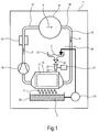
- FIG 1 shows a clothes treatment appliance realized as a household drying appliance 11, in particular a clothes dryer.
- the drying appliance 11 includes a clothes container in form of a rotatable clothes drum 12.
- the drum 12 is connected to an air inlet section 13 and an air outlet section 14 of a process air channel 15.
- Warm air entering the drum 12 via the air inlet section 13 can dry the clothes contained in the drum 12.
- the resulting warm and wet process air P leaves the drum 12 through the air outlet section 14 and flows to a process air condenser 16 that cools the process air P.
- the condenser 16 typically has several plate-like cooling blades 17 that are arranged in a parallel fashion (which in the shown drawing are oriented in parallel to and are spaced apart perpendicular to the viewing plane).
- the condenser 16 and its cooling blades 17, respectively, may be cooled by a fluid medium, such as, for example, water.
- a fluid medium such as, for example, water.
- the condenser may be embodied as a water/air heat exchanger.
- the process air condenser 16 may be an evaporator of a heat pump, e.g. a compressor-type heat pump.
- the process air P is cool and dry and is moved by an appropriate device (for example a fan) to a heater 18 that heats up the process air P to be warm and dry.
- the heater 18 may be, e.g., an electric heater, or a condenser of a heat pump.
- This warm and dry process air P is then re-introduced into the drum 12 via the air inlet section 13.
- an air blower 19 is used to keep up the flow of the process air P.
- a condensate collector 20 e.g. a pan.
- the condensate collector 20 may be integrated in the process air channel 15, e.g. as a bottom of a section of the process air channel 15. From the condensate collector 20, the condensate C is pumped by a pump 21 to a water container 22 located above the condenser 16. A bottom region of the water container 22 is connected to a transfer pipe 23 that leads to the condenser 16.
- a controllable valve 24 that, if opened, allows the condensate C stored in the water container 22 to enter an upper inlet of the transfer pipe 23, flow through the transfer pipe 23, and leave a lower outlet 25 of the transfer pipe 23 as a water gush.
- the transfer pipe 23 is directed such, and the outlet 25 is positioned such that the water gush can clean the condenser 16, in particular cooling blades 17 of the condenser 16.
- the condenser 16 is thus a water-cleanable unit.
- the water-cleanable unit may e.g. be a process air filter 26, in particular if positioned between the drum 12 and the condenser 16.
- the household drying appliance 11 also includes a water accelerator 27 to accelerate the water leaving the transfer pipe 23 and thus to increase to momentum / energy of the water gush and thus to enhance cleaning effectiveness.
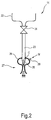
- FIG. 2 shows a sectional side view of one embodiment of the water accelerator 27.
- the water accelerator 27 includes a Venturi nozzle 28 at the outlet 25 of the transfer pipe 23.
- the Venturi nozzle 28 includes an inlet 29 for pressurized medium M, e.g. pressurized air, steam or water.
- the pressurized medium M is used in a well-known manner to create the Venturi effect and to accelerate the condensate C leaving the outlet 25.
- the Venturi nozzle 28 may be integrated into the transfer pipe 23 or may be an attachment to the transfer pipe 23.
- FIG 3 shows a sectional side view of another embodiment of the water accelerator 27.
- the water accelerator 27 includes a pressure generator 30 for generating pressure in the transfer pipe 31 by a compression chamber 32.
- the compression chamber 32 is located downstream from the valve 24 and is realized as a section 33 of the transfer pipe 31.
- the compression chamber 32 is divided into two parts 32a, 32b, namely a first part 32a containing the condensate C coming from the water container 22 and a second part 32b not containing the condensate C.
- the compression chamber 32 further includes a mechanical device in the form of a movable piston 34 that acts as a partition means for the two parts 32a and 32b. Movement of the piston 34 controllably changes a volume of the compression chamber 32 (in particular its first part 32a).
- the second part 32b includes an inlet 35 for a pressure providing medium M that can be opened and closed by a valve 36.
- a spring 37 is located in the second part 32b that pushes the piston 34 in the direction of the first part 32a.
- the valve 24 opens and lets the condensate C flow into the transfer pipe 31.
- the valve 36 opens such that the second part 32b is pressurized (e.g. by an influx of pressurized process air P or tap water) and moves the piston 34 in the direction of the first part 32a. This reduces a volume of the first part 32a and increases pressure of the condensate C.
- the transfer pipe 31 may have another valve 53 (see figure 4 ) downstream from the compression chamber 32.
- valve 53 is closed when the valve 24 is open and may open after the valve 36 has opened and the piston 34 has been moved, or a little later or earlier. Therefore, the piston 34 acts on a contained condensate C that cannot leave the transfer pipe 31 during pressure build-up. After the gush the piston 34 can be removed to initial position. This can be realized by a pulling spiral spring 37 which contracts after pressure release. Alternatively, the piston 34 can be moved by a mechanical or electromechanical device (a linear motor for example).
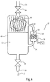
- FIG 4 shows a sectional side view of yet another embodiment of the water accelerator 27 including a steam generator 38 as a pressure generator for generating steam as the pressurized or pressurizing medium.
- the steam generator 38 includes an electric heater 39, an outlet of which is connected to a steam inlet 40 for the steam.
- the steam inlet 40 is also located downstream the valve 24.
- the transfer pipe 31 also shows the valve 53 downstream the inlet 40 for the steam (here at the outlet 25 of pressure container 41).
- the valve 24 is open to feed the condensate C into the pressure container 41 while the valve 53 is closed.
- An opening duration of the valve 24 is such that a water level of the condensate C filling the pressure container 41 is lower than the inlet 40 for the steam.
- the valve 24 is closed such that the pressure container 41 provides a pressure-tight container for the condensate.
- the electric heater 39 is activated and generates steam as the pressurizing medium M. A steam atmosphere builds up above the water level in the pressure container 41 and generates pressure.
- the valve 53 is opened, and the condensate C can leave the transfer pipe 41 with increased speed. After that, the process may be repeated.
- the electric heater 39 To feed the electric heater 39 with water, it is connected by a feed channel 54 to the transfer pipe 41, at a position below the inlet 40 and below the water level.
- the steam generator 38 does not need to have a separate water feed and may only produce pressurized steam M if there is condensate C in the pressure container 41.
- Figure 5 shows a sectional side view of another embodiment of the water accelerator 27 including an impeller 43 within the transfer pipe 23.
- the rotation of impeller 43 pushes the water in the direction of the outlet 25 of the transfer pipe 23.
- Figure 6 shows a sectional side view of a rotating chopper 45 for creating a water hammer effect.
- the rotating chopper 45 is part of a closing device 44 for periodically opening and closing the transfer pipe 46.
- the closing device 44 may generate a series of pressure pulses or spikes of the pressure of the condensate C leaving the transfer pipe 46 in a simple manner.
- the rotating chopper 45 has a disc-shaped body ('rotor') which has at least one through-hole 47 perpendicular to its longitudinal axis L. If there is more than one through-hole 47, they can be located concentrically around the longitudinal axis L.
- the through-hole 47 is alternatingly placed within the transfer pipe 46 (and then opens the transfer pipe 46) or outside the transfer pipe 46 (such that the chopper 45 closes the transfer pipe 46).
- a diameter of the through-hole 47 may correspond to a diameter of the transfer pipe 46 at the cut-out 48, or may be slightly smaller to increase a sealing property.
- Figure 7 shows a bottom view of a closing device 42 including another chopper 49 for creating a water hammer effect.
- This chopper 49 has two disc-shaped bodies 50 and 51.
- the bodies 50 and 51 are concentrically aligned and are only shown offset for easier description of the chopper 49.
- the bodies 50 and 51 are of the same shape and have several through-holes 52.
- the through-holes 52 are shaped like angular sectors of a ring. Of the two disc-shaped bodies 50 and 51, only one body 50 or 51 is rotatable.
- This chopper 49 is placed within the transfer pipe.
- the through-holes 52 of the bodies 50 and 51 alternatingly overlap and are misaligned and thus open or close the transfer pipe, respectively.
Landscapes
- Engineering & Computer Science (AREA)
- Textile Engineering (AREA)
- Detail Structures Of Washing Machines And Dryers (AREA)
- Jet Pumps And Other Pumps (AREA)
Description
- The invention relates to a clothes treatment appliance, including a process air condenser and a water container connected to a transfer pipe leading to a water-cleanable unit of the clothes treatment appliance.
- A typical clothes dryer (as such or as a washer-dryer in combination with a washing function) includes a laundry or clothes container (e.g. a rotatable clothes drum) that is connected to an air inlet and an air outlet of a process air channel. Warm air entering the clothes container via the air inlet of the process channel dries the clothes or laundry. The resulting warm and wet process air leaves the clothes container through the air outlet of the process air channel and flows to a process air condenser that cools the process air. At the condenser, the humidity contained by the process air precipitates. Thus, behind the condenser (with respect to a flow direction of the process air) the process air is cool and dry and flows to a heater that heats up the process air to be warm and dry. This warm and dry process air is then re-introduced into the clothes container via the air inlet. To keep up the flow of the process air, an air blower may be used.
- During the drying process, solid residues, especially fluffs and hair, are released by the clothes and are dragged along with the process air. At the condenser, the fluffs and hair etc. adhere to the precipitated drops of condensate water and at least partly stick to the condenser if the water drops drip from the condenser, typically into a condensate collector, the so called collection pan. To remove particles from the process air prior to the condenser, it is known to place filters into the process air channel between the air outlet and the condenser. However, filters are not effective enough to separate all the particles or residue from the process air flow. Therefore, at the condenser mainly agglomerated lint (from fluff and/or hairs) can be observed even after a few drying operations. These lint agglomerations reduce the condensation effectiveness and may cause a breakdown of the condenser function over time.
- For this sake, the condensation unit is going to be rinsed in appropriate sequences.
- In state of the art appliances the removal of the agglomerations is realized by issuing a water gush where the water is released from a water container above the condenser and flows through a vertical transfer pipe that directs the water to the condenser.
- For example,
EP 2 134 896 B1 andWO 2010/102892 A1 both disclose a cleaning device as described with the water container in an upper region of the drying appliance and the condensation unit in a lower region of the drying appliance. The water container is supplied by condensate water collected from the condenser. - The realization of the described set-ups above is complex. It affords several components and is associated with considerable cost for material and assembly. Also, the water gush often cannot completely clean the condenser, and typically a certain amount of lint remains.
- It is an object of the present invention to overcome or mitigate at least some of the problems associated with the prior art and in particular to provide a clothes treatment appliance with an improved effectiveness for cleaning a condenser.
- An object is achieved by a clothes treatment appliance, including a water container connected to a transfer pipe leading to a water-cleanable unit of the clothes treatment appliance wherein the clothes treatment appliance further includes a water accelerator.
- The water container is typically positioned above the water-cleanable unit such that water released into the transfer pipe can create a water gush at a lower outlet of the transfer pipe to clean the water-cleanable unit. Up to now, the energy and momentum of the water is mainly dependent on the gravitational potential energy of the water and thus on the height of the water container relative to the condenser unit. To increase, in particular amplify, the energy and momentum of the water leaving the transfer pipe and thus to enhance a cleaning effectiveness in particular with respect to the water-cleanable unit, the clothes treatment appliance further includes a water accelerator. The water accelerator also enables the application of a shorter transfer pipe in any geometrical arrangement and thus a more flexible design and/or a more compact set-up.
- In particular, the water-cleanable unit may be a process air condenser. Alternatively or additionally, the water-cleanable unit may e.g. be a process air filter, in particular if it is positioned between a clothes container (e.g. drum) of the clothes treatment appliance and the process air condenser. The filter may be a lint (fluff, hair etc.) filter.
- In an advantageous embodiment the water accelerator includes a pressure generator for generating pressure in the transfer pipe. The pressure increases the energy and momentum of the water leaving the transfer pipe. The pressure generator may have a particularly simple and rugged design or set-up. Also, use of the pressure generator enables a fast-responding build-up (and relaxation) in pressure of the water and thus a precise control of the water gush momentum and energy.
- In an advantageous embodiment the pressure generator includes an inlet for a pressurized medium. This enables a particularly simple set-up. The pressure of the pressurized medium is transferred to the water coming from the water container. The pressurized medium may, e.g., be pressurized process air tapped or bypassed from a process air channel, pressurized air generated by a compressor, steam provided by a steam generator, main (tap) water and/or water output by a pump.
- In a variation, the inlet is connected to the pressure generator to drive the pressure generator. In this case the pressure generator could also be called a pressure transfer device.
- In another variation, the inlet is directly connected to the transfer pipe to directly transfer the pressure to the transfer pipe. In particular, if the inlet is directly connected to the transfer pipe, the pressure generator providing the pressurized medium may be part of the pressure generator, e.g. a valve connected to a tap or main water line, an air compressor, a steam generator and so on.
- In an advantageous embodiment an outlet of the transfer pipe is shaped as a Venturi nozzle that is connected to the inlet for the pressurized medium. Thus, the pressurized medium accelerates the water having flown through the transfer pipe. The Venturi nozzle may be integrated into the transfer pipe or may be an attachment to an existing transfer pipe. For example alternatively, the transfer pipe may have a nozzle / nozzle-like means at another position, e.g. in a midsection. The Venturi nozzle may be regarded as a pressure generator.
- In another advantageous embodiment the pressure generator includes a compression chamber connected to the transfer pipe downstream a valve for controlling a water flow from the water container into the transfer pipe and wherein the compression chamber includes a mechanical device for controllably changing a volume of the compression chamber. This enables a particular high pressure.
- The mechanical device may, e.g., include a piston or a deformable membrane. The membrane may be made of rubber, etc. The piston may be pushed in the direction of the transfer pipe to reduce the volume available for the water e.g. by pressure (pressured air, steam or water). In this case the compression chamber may be regarded as a pressure transfer device. The membrane may in particular be pushed in the direction of the transfer pipe by pressure to reduce the volume available for the water e.g. by pressure (pressured air, steam or water).
- Alternatively, the mechanical device may be moved or driven by a motor (electric motor, hydraulic motor and so on), in particular if the mechanical device is a piston.
- In an advantageous embodiment the compression chamber is a section of the transfer pipe. This enables an easy assembly and, particularly, a compact design.
- It is generally advantageous that the pressure generator is connected to the transfer pipe downstream (with respect to the water coming from the water container) a valve for controlling a water flow from the water container into the transfer pipe. This prevents a spillback of the water into the water container and maintains the pressure in the transfer pipe if this valve is closed. To adjust activation of the valve and the water accelerator, the clothes treatment appliance may e.g. include a controller (for example a microcontroller) for controlling the valve and the water accelerator.
- Generally, the valve may be a controlled / active valve or be a passive valve like a flap or a back-pressure valve etc.
- The valve may, e.g., be integrated with an outlet of the water tank, be located between the water tank and the transfer pipe, or be integrated with the transfer pipe.
- In yet another advantageous embodiment the pressure generator includes a steam generator for generating steam as the pressurized medium and wherein a steam outlet of the steam generator is connected to the transfer pipe downstream a valve for controlling a water flow from the water container into the transfer pipe. The use of a steam generator may enable a particularly compact design. The steam generator may include an electric heater.
- To feed the electric heater with water, it may be connected to the transfer pipe, in particular, at a position of the transfer pipe below the connection to its steam outlet. This has an advantage that the steam generator does not need a separate water feed and may produce pressurized steam if there is water in the transfer pipe but does not generate steam if the transfer pipe is empty.
- In yet another advantageous embodiment the water accelerator includes an impeller within the transfer pipe. The rotation of the impeller pushes the water in the direction of the outlet of the transfer pipe. Use of the impeller has an advantage that this embodiment allows for a particularly compact design.
- In another advantageous embodiment the clothes treatment appliance is adapted to apply a water hammer effect (shock wave) on the water in the transfer pipe. The water hammer effect may in particular include a modulation of the pressure of the water leaving the transfer pipe. The modulation may, in particular, include a series of pressure pulses or spikes, in particular, a periodic series. The water hammer effect enhances the cleaning effectiveness even further.
- In an advantageous embodiment the water hammer effect is achieved by modulating a pressure generated by the pressure generator.
- In another advantageous embodiment the transfer pipe includes a closing device downstream of the water accelerator for periodically opening and closing the transfer pipe. Thus, the closing device may generate a series of pressure pulses or spikes in a simple manner.
- In particular, the closing device may include a rotating chopper. The rotating chopper may be operated by a motor.
- In one embodiment the rotating chopper has a cylinder-shaped body which has a through-hole perpendicular to its longitudinal axis. By placing the section of the chopper that includes the through-hole within the transfer pipe and by rotating the chopper around its longitudinal axis, the through-hole is alternatingly aligned parallel to the transfer pipe (and then fully opens the transfer pipe) and perpendicular to the transfer pipe (and then closes the transfer pipe). The longitudinal axis of the chopper may in particular be oriented perpendicular to a longitudinal axis of the transfer pipe, e.g. horizontally. This embodiment has an advantage that the chopper has a fixed position with respect to the down pipe which simplifies a pressure-tight sealing. The chopper may be fixed to the transfer pipe by a pivot bearing.
- In another advantageous embodiment the rotating chopper has a disc-shaped body ('rotor') which has one or more through-holes parallel to its longitudinal axis. If there is more than one through-hole, they are advantageously located concentrically around a longitudinal axis of the chopper. By placing a section of the rotor that includes a through-hole into a cut-out of the transfer pipe and by rotating the rotor around its longitudinal axis, the through-hole is alternatingly placed within the transfer pipe (and then opens the transfer pipe) or outside the transfer pipe (such that the chopper closes the transfer pipe). It is advantageous that a distance between the through-holes is such that the transfer pipe is alternatingly opened and closed by the rotation rotor. Advantageously, the plane of the disc-shaped rotor (perpendicular to the longitudinal axis) is oriented perpendicular to the longitudinal axis of the transfer pipe, e.g. horizontally, and the longitudinal axis is oriented parallel to the longitudinal axis of the transfer pipe.
- In yet another advantageous embodiment the chopper has two disc-shaped bodies, both of which have one or more through-holes. The two disc-shaped bodies may in particular have the same or a very similar shape and a same location and size of the through-hole. Of the two disc-shaped bodies, at least one body is rotatable ('rotor'), or e.g. both bodies are rotatable but in a different direction. This chopper may be placed within the transfer pipe. During operation, the through-holes of the two discs alternatingly overlap or are misaligned and thus leave the transfer pipe open or close the transfer pipe , respectively.
- The clothes treatment appliance may in particular be a clothes drying appliance, e.g. a clothes dryer or a washer-dryer.
- The clothes treatment appliance may in particular be a household appliance.
- In the figures of the attached drawing, the invention is schematically described in more detail by means of several exemplary embodiments. Same or functionally equivalent elements may be denoted by the same reference numerals. In particular,
- Fig.1
- shows a sectional side view of a household drying appliance including a water accelerator;
- Fig.2
- shows a sectional side view of one embodiment of the water accelerator;
- Fig.3
- shows a sectional side view of another embodiment of the water accelerator;
- Fig.4
- shows a sectional side view of yet another embodiment of the water accelerator;
- Fig.5
- shows a sectional side view of even another embodiment of the water accelerator;
- Fig.6
- shows a sectional side view of a chopper for creating a water hammer effect; and
- Fig.7
- shows a bottom view of another chopper 49 for creating a water hammer effect.
-
Figure 1 shows a clothes treatment appliance realized as ahousehold drying appliance 11, in particular a clothes dryer. The dryingappliance 11 includes a clothes container in form of a rotatable clothes drum 12. Thedrum 12 is connected to anair inlet section 13 and anair outlet section 14 of aprocess air channel 15. Warm air entering thedrum 12 via theair inlet section 13 can dry the clothes contained in thedrum 12. The resulting warm and wet process air P leaves thedrum 12 through theair outlet section 14 and flows to aprocess air condenser 16 that cools the process air P. Thus, at thecondenser 16, the process air precipitates. To cool the process air P, thecondenser 16 typically has several plate-like cooling blades 17 that are arranged in a parallel fashion (which in the shown drawing are oriented in parallel to and are spaced apart perpendicular to the viewing plane). - The
condenser 16 and itscooling blades 17, respectively, may be cooled by a fluid medium, such as, for example, water. In this case, the condenser may be embodied as a water/air heat exchanger. Alternatively, theprocess air condenser 16 may be an evaporator of a heat pump, e.g. a compressor-type heat pump. - Behind or downstream the
condenser 16, the process air P is cool and dry and is moved by an appropriate device (for example a fan) to aheater 18 that heats up the process air P to be warm and dry. Theheater 18 may be, e.g., an electric heater, or a condenser of a heat pump. - This warm and dry process air P is then re-introduced into the
drum 12 via theair inlet section 13. To keep up the flow of the process air P, anair blower 19 is used. - To collect the condensate C dripping from the
condenser 16, underneath there is located acondensate collector 20, e.g. a pan. Thecondensate collector 20 may be integrated in theprocess air channel 15, e.g. as a bottom of a section of theprocess air channel 15. From thecondensate collector 20, the condensate C is pumped by apump 21 to awater container 22 located above thecondenser 16. A bottom region of thewater container 22 is connected to atransfer pipe 23 that leads to thecondenser 16. Between thewater container 22 and thetransfer pipe 23 is acontrollable valve 24 that, if opened, allows the condensate C stored in thewater container 22 to enter an upper inlet of thetransfer pipe 23, flow through thetransfer pipe 23, and leave alower outlet 25 of thetransfer pipe 23 as a water gush. Thetransfer pipe 23 is directed such, and theoutlet 25 is positioned such that the water gush can clean thecondenser 16, inparticular cooling blades 17 of thecondenser 16. Thecondenser 16 is thus a water-cleanable unit. - Alternatively or additionally, the water-cleanable unit may e.g. be a
process air filter 26, in particular if positioned between thedrum 12 and thecondenser 16. - The
household drying appliance 11 also includes awater accelerator 27 to accelerate the water leaving thetransfer pipe 23 and thus to increase to momentum / energy of the water gush and thus to enhance cleaning effectiveness. -
Figure 2 shows a sectional side view of one embodiment of thewater accelerator 27. Thewater accelerator 27 includes aVenturi nozzle 28 at theoutlet 25 of thetransfer pipe 23. TheVenturi nozzle 28 includes aninlet 29 for pressurized medium M, e.g. pressurized air, steam or water. The pressurized medium M is used in a well-known manner to create the Venturi effect and to accelerate the condensate C leaving theoutlet 25. TheVenturi nozzle 28 may be integrated into thetransfer pipe 23 or may be an attachment to thetransfer pipe 23. -
Figure 3 shows a sectional side view of another embodiment of thewater accelerator 27. Here, thewater accelerator 27 includes a pressure generator 30 for generating pressure in thetransfer pipe 31 by a compression chamber 32. The compression chamber 32 is located downstream from thevalve 24 and is realized as a section 33 of thetransfer pipe 31. The compression chamber 32 is divided into twoparts first part 32a containing the condensate C coming from thewater container 22 and asecond part 32b not containing the condensate C. The compression chamber 32 further includes a mechanical device in the form of amovable piston 34 that acts as a partition means for the twoparts piston 34 controllably changes a volume of the compression chamber 32 (in particular itsfirst part 32a). This enables a particular high pressure of the condensate C within thetransfer pipe 31. To this effect, thesecond part 32b includes aninlet 35 for a pressure providing medium M that can be opened and closed by avalve 36. To increase the pressure and to facilitate a movement of thepiston 34 in the direction of thefirst part 32a (to decrease its volume), aspring 37 is located in thesecond part 32b that pushes thepiston 34 in the direction of thefirst part 32a. - During one possible mode of operation, the
valve 24 opens and lets the condensate C flow into thetransfer pipe 31. When thevalve 24 closes, thevalve 36 opens such that thesecond part 32b is pressurized (e.g. by an influx of pressurized process air P or tap water) and moves thepiston 34 in the direction of thefirst part 32a. This reduces a volume of thefirst part 32a and increases pressure of the condensate C. - To increase a pressure of the condensate C within the
transfer pipe 31, thetransfer pipe 31 may have another valve 53 (seefigure 4 ) downstream from the compression chamber 32. - During another possible mode of operation, the
valve 53 is closed when thevalve 24 is open and may open after thevalve 36 has opened and thepiston 34 has been moved, or a little later or earlier. Therefore, thepiston 34 acts on a contained condensate C that cannot leave thetransfer pipe 31 during pressure build-up. After the gush thepiston 34 can be removed to initial position. This can be realized by a pullingspiral spring 37 which contracts after pressure release. Alternatively, thepiston 34 can be moved by a mechanical or electromechanical device (a linear motor for example). -
Figure 4 shows a sectional side view of yet another embodiment of thewater accelerator 27 including asteam generator 38 as a pressure generator for generating steam as the pressurized or pressurizing medium. Thesteam generator 38 includes anelectric heater 39, an outlet of which is connected to asteam inlet 40 for the steam. Thesteam inlet 40 is also located downstream thevalve 24. Thetransfer pipe 31 also shows thevalve 53 downstream theinlet 40 for the steam (here at theoutlet 25 of pressure container 41). - In one mode of operation, the
valve 24 is open to feed the condensate C into thepressure container 41 while thevalve 53 is closed. An opening duration of thevalve 24 is such that a water level of the condensate C filling thepressure container 41 is lower than theinlet 40 for the steam. Then thevalve 24 is closed such that thepressure container 41 provides a pressure-tight container for the condensate. In a further step, theelectric heater 39 is activated and generates steam as the pressurizing medium M. A steam atmosphere builds up above the water level in thepressure container 41 and generates pressure. In a next step, thevalve 53 is opened, and the condensate C can leave thetransfer pipe 41 with increased speed. After that, the process may be repeated. - To feed the
electric heater 39 with water, it is connected by afeed channel 54 to thetransfer pipe 41, at a position below theinlet 40 and below the water level. Thus, thesteam generator 38 does not need to have a separate water feed and may only produce pressurized steam M if there is condensate C in thepressure container 41. -
Figure 5 shows a sectional side view of another embodiment of thewater accelerator 27 including animpeller 43 within thetransfer pipe 23. The rotation ofimpeller 43 pushes the water in the direction of theoutlet 25 of thetransfer pipe 23. -
Figure 6 shows a sectional side view of arotating chopper 45 for creating a water hammer effect. The rotatingchopper 45 is part of aclosing device 44 for periodically opening and closing thetransfer pipe 46. Thus, the closingdevice 44 may generate a series of pressure pulses or spikes of the pressure of the condensate C leaving thetransfer pipe 46 in a simple manner. - The rotating
chopper 45 has a disc-shaped body ('rotor') which has at least one through-hole 47 perpendicular to its longitudinal axis L. If there is more than one through-hole 47, they can be located concentrically around the longitudinal axis L. By placing a section of thechopper 45 that includes the through-hole 47 into a cut-out 48 of thetransfer pipe 46 and by rotating or oscillating thechopper 45 around its longitudinal axis L, the through-hole 47 is alternatingly placed within the transfer pipe 46 (and then opens the transfer pipe 46) or outside the transfer pipe 46 (such that thechopper 45 closes the transfer pipe 46). To allow a large opening cross section, a diameter of the through-hole 47 may correspond to a diameter of thetransfer pipe 46 at the cut-out 48, or may be slightly smaller to increase a sealing property. -
Figure 7 shows a bottom view of a closing device 42 including another chopper 49 for creating a water hammer effect. This chopper 49 has two disc-shapedbodies bodies bodies holes 52. The through-holes 52 are shaped like angular sectors of a ring. Of the two disc-shapedbodies body - This chopper 49 is placed within the transfer pipe. During rotation, the through-
holes 52 of thebodies - Of course, the present invention is not limited to the described embodiments.
-
- 11
- household drying appliance, clothes dryer
- 12
- drum
- 13
- air inlet section
- 14
- air outlet section
- 15
- process air channel
- 16
- process air condenser
- P
- process air
- 17
- cooling blade
- 18
- heater
- 19
- air blower
- C
- condensate
- 20
- condensate collector, pan
- 21
- pump
- 22
- water container
- 23
- transfer pipe
- 24
- valve
- 25
- lower outlet
- 26
- process air filter
- 27
- water accelerator
- 28
- Venturi nozzle
- 29
- inlet
- M
- pressurized medium
- 30
- pressure generator
- 31
- transfer pipe
- 32
- compression chamber
- 32a
- first part of compression chamber
- 32b
- second part of compression chamber
- 33
- section of
transfer pipe 31 - 34
- piston
- 35
- inlet
- 36
- valve
- 37
- spring
- 38
- steam generator
- 39
- electric heater
- 40
- steam inlet
- 41
- pressure container
- 43
- impeller
- 44
- closing device
- 45
- chopper
- 46
- transfer pipe
- 47
- through-hole
- 48
- cut-out
- 49
- chopper
- 50
- first disc-shaped body
- 51
- second disc-shaped body
- 52
- through-hole
- 53
- valve
- 54
- feed channel
Claims (14)
- A clothes treatment appliance (11), comprising:a water container (22) connected to a transfer pipe (23) leading to a water-cleanable unit (16), said water container (22) positioned above said water-cleanable unit (16) such that water released into said transfer pipe (23) can create a water gush at a lower outlet (25) of said transfer pipe (23) to clean the water-cleanable unit (16) ; characterized bya water accelerator (27) that comprises a pressure generator (30, 43) for generating pressure in the transfer pipe (23).
- The clothes treatment (11) appliance of claim 1, wherein said water-cleanable unit (16) is a process air condenser (16).
- The clothes treatment (11) appliance of claim 1, wherein the pressure generator (30, 43) comprises an inlet (29) for a pressurized medium (M).
- The clothes treatment (11) appliance of claim 1, wherein the pressure generator (30, 43) comprises a compression chamber (32) connected to the transfer pipe (23) downstream from a valve (24) that controls a water flow from the water container (22) into the transfer pipe (23) and wherein the compression chamber (32) comprises a mechanical or electromechanical device (34, 35, 36, 37) that controllably changes a volume of the compression chamber (32).
- The clothes treatment appliance (11) of claim 4, wherein the compression chamber (32) is a section of the transfer pipe (23).
- The clothes treatment appliance (11) of claim 1, wherein the pressure generator (30, 43) comprises a steam generator (38) for generating steam as a pressurized medium (M), and wherein an outlet of the steam generator (38) is connected to the transfer pipe (23) downstream from a valve (24) that controls a water flow from the water container (22) into the transfer pipe (23).
- The clothes treatment (11) appliance of claim 1, wherein a section of the transfer pipe (23) is shaped as a Venturi nozzle (28) that is connected to an inlet (29) for a pressurized medium (M).
- The clothes treatment (11) appliance of claim 1, wherein the water accelerator (27) comprises an impeller (43) within the transfer pipe (23).
- The clothes treatment (11) appliance of claim 1, wherein the clothes treatment appliance (11) is adapted to apply a water hammer effect on water in the transfer pipe (23).
- The clothes treatment (11) appliance of claim 9, wherein the water hammer effect is achieved by modulating a pressure generated by a pressure generator (30, 43).
- The clothes treatment appliance (11) of claim 9, wherein the transfer pipe (23) comprises a closing device (44) downstream from the water accelerator (27) for periodically opening and closing the transfer pipe (23).
- The clothes treatment appliance (11) of claim 11, wherein the closing device (44) comprises a rotating device (43, 45) as an impeller (43) or a chopper (45).
- The clothes treatment appliance (11) of claim 1, wherein the clothes treatment appliance (11) is a clothes drying appliance (11).
- The clothes treatment appliance (11) of claim 1, wherein the clothes treatment appliance (1,1) is a household appliance (11).
Applications Claiming Priority (3)
| Application Number | Priority Date | Filing Date | Title |
|---|---|---|---|
| US13/431,101 US20130255331A1 (en) | 2012-03-27 | 2012-03-27 | Clothes treatment appliance with water container and downpipe |
| US13/469,136 US20130255094A1 (en) | 2012-03-27 | 2012-05-11 | Clothes treatment appliance with water container and a transfer pipe |
| PCT/IB2013/052079 WO2013144764A1 (en) | 2012-03-27 | 2013-03-15 | Clothes treatment appliance with water container and a transfer pipe |
Publications (2)
| Publication Number | Publication Date |
|---|---|
| EP2831332A1 EP2831332A1 (en) | 2015-02-04 |
| EP2831332B1 true EP2831332B1 (en) | 2016-05-18 |
Family
ID=48325800
Family Applications (1)
| Application Number | Title | Priority Date | Filing Date |
|---|---|---|---|
| EP13721072.0A Not-in-force EP2831332B1 (en) | 2012-03-27 | 2013-03-15 | Clothes treatment appliance with water container and a transfer pipe |
Country Status (4)
| Country | Link |
|---|---|
| US (1) | US20130255094A1 (en) |
| EP (1) | EP2831332B1 (en) |
| PL (1) | PL2831332T3 (en) |
| WO (1) | WO2013144764A1 (en) |
Families Citing this family (14)
| Publication number | Priority date | Publication date | Assignee | Title |
|---|---|---|---|---|
| US20130255331A1 (en) * | 2012-03-27 | 2013-10-03 | Bsh Bosch Und Siemens Hausgerate Gmbh | Clothes treatment appliance with water container and downpipe |
| US9382658B2 (en) * | 2012-12-18 | 2016-07-05 | Mohamed H. Tarifi | Lint trap |
| US9562707B2 (en) | 2013-03-14 | 2017-02-07 | Whirlpool Corporation | Refrigerator cooling system having a secondary cooling loop |
| DE102015200331A1 (en) * | 2015-01-13 | 2016-07-14 | BSH Hausgeräte GmbH | Condensation dryer with a heat exchanger and a flushing device for this, as well as method for its operation |
| US10633785B2 (en) | 2016-08-10 | 2020-04-28 | Whirlpool Corporation | Maintenance free dryer having multiple self-cleaning lint filters |
| US10519591B2 (en) | 2016-10-14 | 2019-12-31 | Whirlpool Corporation | Combination washing/drying laundry appliance having a heat pump system with reversible condensing and evaporating heat exchangers |
| US10738411B2 (en) | 2016-10-14 | 2020-08-11 | Whirlpool Corporation | Filterless air-handling system for a heat pump laundry appliance |
| US10502478B2 (en) | 2016-12-20 | 2019-12-10 | Whirlpool Corporation | Heat rejection system for a condenser of a refrigerant loop within an appliance |
| US10544539B2 (en) | 2017-02-27 | 2020-01-28 | Whirlpool Corporation | Heat exchanger filter for self lint cleaning system in dryer appliance |
| US10514194B2 (en) | 2017-06-01 | 2019-12-24 | Whirlpool Corporation | Multi-evaporator appliance having a multi-directional valve for delivering refrigerant to the evaporators |
| US10718082B2 (en) | 2017-08-11 | 2020-07-21 | Whirlpool Corporation | Acoustic heat exchanger treatment for a laundry appliance having a heat pump system |
| US11015281B2 (en) | 2017-09-26 | 2021-05-25 | Whirlpool Corporation | Laundry appliance having a maintenance free lint removal system |
| CN110130072B (en) * | 2019-03-25 | 2020-12-18 | 嘉兴市发扬喷织有限公司 | Textile drying device |
| CN113737493B (en) * | 2021-09-13 | 2026-02-17 | 重庆海尔滚筒洗衣机有限公司 | Condensing container and clothes treating apparatus |
Family Cites Families (13)
| Publication number | Priority date | Publication date | Assignee | Title |
|---|---|---|---|---|
| GB1112337A (en) * | 1965-10-22 | 1968-05-01 | Whirlpool Co | Improvements in or relating to laundry apparatus |
| IT1083106B (en) * | 1977-05-17 | 1985-05-21 | Pagnozzi Vincenzo | EMPTY DRYER PARTICULARLY FOR TIMBER |
| DE2806873C3 (en) * | 1978-02-17 | 1981-03-26 | Bauknecht Hausgeräte GmbH, 70565 Stuttgart | Drum washing and drying machine |
| US4319410A (en) * | 1980-06-24 | 1982-03-16 | The Brandt Company | Dryer system for drilling mud cuttings |
| AU571845B2 (en) * | 1983-08-19 | 1988-04-28 | Barry Bros. Specialised Services Pty Ltd | Pig, launcher and catcher for tube or pipe cleaning |
| IT1192075B (en) * | 1986-04-09 | 1988-03-31 | Zanussi Elettrodomestici | HOUSEHOLD APPLIANCE MACHINE FOR LAUNDRY WASHING AND DRYING |
| CA2421300A1 (en) * | 2000-09-05 | 2003-03-04 | Naoki Ohta | Rankine cycle system |
| KR101328920B1 (en) * | 2006-09-18 | 2013-11-14 | 엘지전자 주식회사 | laundry dryer |
| DE602007007287D1 (en) * | 2007-02-23 | 2010-08-05 | Electrolux Home Prod Corp | Clothes dryers for the household |
| DE102007016074A1 (en) * | 2007-04-03 | 2008-10-09 | BSH Bosch und Siemens Hausgeräte GmbH | Method and device for cleaning a component, in particular an evaporator of a condenser device, and laundry or tumble dryer with such a device |
| ES2351260T3 (en) * | 2007-05-11 | 2011-02-02 | Electrolux Home Products Corporation N.V. | DRESS DRESS IMPROVED WITH RESTORATION OPERATION. |
| DE102009001548A1 (en) | 2009-03-13 | 2010-09-16 | BSH Bosch und Siemens Hausgeräte GmbH | A laundry drying apparatus having a lint filter disposed within a process air cycle and method of operating the laundry dryer |
| US20120005912A1 (en) * | 2010-07-08 | 2012-01-12 | Lee Yongju | Clothes dryer |
-
2012
- 2012-05-11 US US13/469,136 patent/US20130255094A1/en not_active Abandoned
-
2013
- 2013-03-15 EP EP13721072.0A patent/EP2831332B1/en not_active Not-in-force
- 2013-03-15 WO PCT/IB2013/052079 patent/WO2013144764A1/en not_active Ceased
- 2013-03-15 PL PL13721072.0T patent/PL2831332T3/en unknown
Also Published As
| Publication number | Publication date |
|---|---|
| PL2831332T3 (en) | 2016-11-30 |
| WO2013144764A1 (en) | 2013-10-03 |
| US20130255094A1 (en) | 2013-10-03 |
| EP2831332A1 (en) | 2015-02-04 |
Similar Documents
| Publication | Publication Date | Title |
|---|---|---|
| US20130255094A1 (en) | Clothes treatment appliance with water container and a transfer pipe | |
| US20130340797A1 (en) | Clothes treatment appliance with transfer pipe | |
| US20130255095A1 (en) | Clothes treatment appliance with condenser and cleaning device | |
| EP2246470B1 (en) | Washer-drier machine | |
| US7997006B2 (en) | Laundry machine and control method thereof | |
| EP2628846A1 (en) | Laundry treatment apparatus with heat exchanger cleaning | |
| ES2383236T3 (en) | Procedure for treating laundry in a washing machine and washing machine | |
| US8161662B2 (en) | Method for operating a laundry appliance having a steam generator device, and laundry appliance | |
| US20130255331A1 (en) | Clothes treatment appliance with water container and downpipe | |
| US20090235957A1 (en) | Method for controlling dishwasher | |
| JP2012223358A (en) | Dryer | |
| EP2163682B1 (en) | Home laundry drier | |
| EP2826909A1 (en) | Method for operating a steam generation unit in a laundry dryer and method of operating a laundry dryer | |
| US20130255097A1 (en) | Clothes treatment appliance with condenser and cleaning device | |
| KR20090123936A (en) | Method and apparatus for cleaning components, especially evaporator of condenser apparatus, and laundry / dryer or tumble dryer comprising such apparatus | |
| MX2008011099A (en) | Fabric treatment appliance with steam backflow device. | |
| AU2008200122A1 (en) | Laundry machine and control method thereof | |
| CN113944040B (en) | Control method for laundry treatment apparatus and laundry treatment apparatus | |
| CN107931223A (en) | Smoke machine cleaning method and the smoke machine using it and automatically controlled flow | |
| KR100774217B1 (en) | dryer | |
| KR20180097326A (en) | Cloth treating apparatus | |
| JP2011092541A (en) | Washing machine | |
| CN106222976B (en) | Device for clothing processing | |
| CN208907180U (en) | A clothing treatment device | |
| CN110393449A (en) | A kind of cooker with steaming function |
Legal Events
| Date | Code | Title | Description |
|---|---|---|---|
| PUAI | Public reference made under article 153(3) epc to a published international application that has entered the european phase |
Free format text: ORIGINAL CODE: 0009012 |
|
| 17P | Request for examination filed |
Effective date: 20141027 |
|
| AK | Designated contracting states |
Kind code of ref document: A1 Designated state(s): AL AT BE BG CH CY CZ DE DK EE ES FI FR GB GR HR HU IE IS IT LI LT LU LV MC MK MT NL NO PL PT RO RS SE SI SK SM TR |
|
| AX | Request for extension of the european patent |
Extension state: BA ME |
|
| RAP1 | Party data changed (applicant data changed or rights of an application transferred) |
Owner name: BSH HAUSGERAETE GMBH |
|
| DAX | Request for extension of the european patent (deleted) | ||
| GRAP | Despatch of communication of intention to grant a patent |
Free format text: ORIGINAL CODE: EPIDOSNIGR1 |
|
| INTG | Intention to grant announced |
Effective date: 20151214 |
|
| GRAS | Grant fee paid |
Free format text: ORIGINAL CODE: EPIDOSNIGR3 |
|
| GRAA | (expected) grant |
Free format text: ORIGINAL CODE: 0009210 |
|
| AK | Designated contracting states |
Kind code of ref document: B1 Designated state(s): AL AT BE BG CH CY CZ DE DK EE ES FI FR GB GR HR HU IE IS IT LI LT LU LV MC MK MT NL NO PL PT RO RS SE SI SK SM TR |
|
| REG | Reference to a national code |
Ref country code: GB Ref legal event code: FG4D |
|
| REG | Reference to a national code |
Ref country code: CH Ref legal event code: EP |
|
| REG | Reference to a national code |
Ref country code: IE Ref legal event code: FG4D Ref country code: AT Ref legal event code: REF Ref document number: 800576 Country of ref document: AT Kind code of ref document: T Effective date: 20160615 |
|
| REG | Reference to a national code |
Ref country code: DE Ref legal event code: R096 Ref document number: 602013007677 Country of ref document: DE |
|
| REG | Reference to a national code |
Ref country code: NL Ref legal event code: MP Effective date: 20160518 |
|
| REG | Reference to a national code |
Ref country code: LT Ref legal event code: MG4D |
|
| PG25 | Lapsed in a contracting state [announced via postgrant information from national office to epo] |
Ref country code: NO Free format text: LAPSE BECAUSE OF FAILURE TO SUBMIT A TRANSLATION OF THE DESCRIPTION OR TO PAY THE FEE WITHIN THE PRESCRIBED TIME-LIMIT Effective date: 20160818 Ref country code: NL Free format text: LAPSE BECAUSE OF FAILURE TO SUBMIT A TRANSLATION OF THE DESCRIPTION OR TO PAY THE FEE WITHIN THE PRESCRIBED TIME-LIMIT Effective date: 20160518 Ref country code: LT Free format text: LAPSE BECAUSE OF FAILURE TO SUBMIT A TRANSLATION OF THE DESCRIPTION OR TO PAY THE FEE WITHIN THE PRESCRIBED TIME-LIMIT Effective date: 20160518 Ref country code: FI Free format text: LAPSE BECAUSE OF FAILURE TO SUBMIT A TRANSLATION OF THE DESCRIPTION OR TO PAY THE FEE WITHIN THE PRESCRIBED TIME-LIMIT Effective date: 20160518 |
|
| REG | Reference to a national code |
Ref country code: AT Ref legal event code: MK05 Ref document number: 800576 Country of ref document: AT Kind code of ref document: T Effective date: 20160518 |
|
| PG25 | Lapsed in a contracting state [announced via postgrant information from national office to epo] |
Ref country code: LV Free format text: LAPSE BECAUSE OF FAILURE TO SUBMIT A TRANSLATION OF THE DESCRIPTION OR TO PAY THE FEE WITHIN THE PRESCRIBED TIME-LIMIT Effective date: 20160518 Ref country code: RS Free format text: LAPSE BECAUSE OF FAILURE TO SUBMIT A TRANSLATION OF THE DESCRIPTION OR TO PAY THE FEE WITHIN THE PRESCRIBED TIME-LIMIT Effective date: 20160518 Ref country code: HR Free format text: LAPSE BECAUSE OF FAILURE TO SUBMIT A TRANSLATION OF THE DESCRIPTION OR TO PAY THE FEE WITHIN THE PRESCRIBED TIME-LIMIT Effective date: 20160518 Ref country code: GR Free format text: LAPSE BECAUSE OF FAILURE TO SUBMIT A TRANSLATION OF THE DESCRIPTION OR TO PAY THE FEE WITHIN THE PRESCRIBED TIME-LIMIT Effective date: 20160819 Ref country code: ES Free format text: LAPSE BECAUSE OF FAILURE TO SUBMIT A TRANSLATION OF THE DESCRIPTION OR TO PAY THE FEE WITHIN THE PRESCRIBED TIME-LIMIT Effective date: 20160518 Ref country code: PT Free format text: LAPSE BECAUSE OF FAILURE TO SUBMIT A TRANSLATION OF THE DESCRIPTION OR TO PAY THE FEE WITHIN THE PRESCRIBED TIME-LIMIT Effective date: 20160919 Ref country code: SE Free format text: LAPSE BECAUSE OF FAILURE TO SUBMIT A TRANSLATION OF THE DESCRIPTION OR TO PAY THE FEE WITHIN THE PRESCRIBED TIME-LIMIT Effective date: 20160518 |
|
| PG25 | Lapsed in a contracting state [announced via postgrant information from national office to epo] |
Ref country code: EE Free format text: LAPSE BECAUSE OF FAILURE TO SUBMIT A TRANSLATION OF THE DESCRIPTION OR TO PAY THE FEE WITHIN THE PRESCRIBED TIME-LIMIT Effective date: 20160518 Ref country code: CZ Free format text: LAPSE BECAUSE OF FAILURE TO SUBMIT A TRANSLATION OF THE DESCRIPTION OR TO PAY THE FEE WITHIN THE PRESCRIBED TIME-LIMIT Effective date: 20160518 Ref country code: DK Free format text: LAPSE BECAUSE OF FAILURE TO SUBMIT A TRANSLATION OF THE DESCRIPTION OR TO PAY THE FEE WITHIN THE PRESCRIBED TIME-LIMIT Effective date: 20160518 Ref country code: RO Free format text: LAPSE BECAUSE OF FAILURE TO SUBMIT A TRANSLATION OF THE DESCRIPTION OR TO PAY THE FEE WITHIN THE PRESCRIBED TIME-LIMIT Effective date: 20160518 Ref country code: SK Free format text: LAPSE BECAUSE OF FAILURE TO SUBMIT A TRANSLATION OF THE DESCRIPTION OR TO PAY THE FEE WITHIN THE PRESCRIBED TIME-LIMIT Effective date: 20160518 |
|
| REG | Reference to a national code |
Ref country code: DE Ref legal event code: R097 Ref document number: 602013007677 Country of ref document: DE |
|
| PG25 | Lapsed in a contracting state [announced via postgrant information from national office to epo] |
Ref country code: SM Free format text: LAPSE BECAUSE OF FAILURE TO SUBMIT A TRANSLATION OF THE DESCRIPTION OR TO PAY THE FEE WITHIN THE PRESCRIBED TIME-LIMIT Effective date: 20160518 Ref country code: AT Free format text: LAPSE BECAUSE OF FAILURE TO SUBMIT A TRANSLATION OF THE DESCRIPTION OR TO PAY THE FEE WITHIN THE PRESCRIBED TIME-LIMIT Effective date: 20160518 Ref country code: BE Free format text: LAPSE BECAUSE OF FAILURE TO SUBMIT A TRANSLATION OF THE DESCRIPTION OR TO PAY THE FEE WITHIN THE PRESCRIBED TIME-LIMIT Effective date: 20160518 |
|
| PLBE | No opposition filed within time limit |
Free format text: ORIGINAL CODE: 0009261 |
|
| STAA | Information on the status of an ep patent application or granted ep patent |
Free format text: STATUS: NO OPPOSITION FILED WITHIN TIME LIMIT |
|
| 26N | No opposition filed |
Effective date: 20170221 |
|
| PG25 | Lapsed in a contracting state [announced via postgrant information from national office to epo] |
Ref country code: SI Free format text: LAPSE BECAUSE OF FAILURE TO SUBMIT A TRANSLATION OF THE DESCRIPTION OR TO PAY THE FEE WITHIN THE PRESCRIBED TIME-LIMIT Effective date: 20160518 |
|
| PGFP | Annual fee paid to national office [announced via postgrant information from national office to epo] |
Ref country code: TR Payment date: 20170313 Year of fee payment: 5 |
|
| PGFP | Annual fee paid to national office [announced via postgrant information from national office to epo] |
Ref country code: IT Payment date: 20170323 Year of fee payment: 5 |
|
| REG | Reference to a national code |
Ref country code: CH Ref legal event code: PL |
|
| PG25 | Lapsed in a contracting state [announced via postgrant information from national office to epo] |
Ref country code: MC Free format text: LAPSE BECAUSE OF FAILURE TO SUBMIT A TRANSLATION OF THE DESCRIPTION OR TO PAY THE FEE WITHIN THE PRESCRIBED TIME-LIMIT Effective date: 20160518 |
|
| REG | Reference to a national code |
Ref country code: IE Ref legal event code: MM4A |
|
| REG | Reference to a national code |
Ref country code: FR Ref legal event code: ST Effective date: 20171130 |
|
| PG25 | Lapsed in a contracting state [announced via postgrant information from national office to epo] |
Ref country code: FR Free format text: LAPSE BECAUSE OF NON-PAYMENT OF DUE FEES Effective date: 20170331 Ref country code: LU Free format text: LAPSE BECAUSE OF NON-PAYMENT OF DUE FEES Effective date: 20170315 |
|
| PG25 | Lapsed in a contracting state [announced via postgrant information from national office to epo] |
Ref country code: CH Free format text: LAPSE BECAUSE OF NON-PAYMENT OF DUE FEES Effective date: 20170331 Ref country code: LI Free format text: LAPSE BECAUSE OF NON-PAYMENT OF DUE FEES Effective date: 20170331 Ref country code: IE Free format text: LAPSE BECAUSE OF NON-PAYMENT OF DUE FEES Effective date: 20170315 |
|
| PG25 | Lapsed in a contracting state [announced via postgrant information from national office to epo] |
Ref country code: MT Free format text: LAPSE BECAUSE OF NON-PAYMENT OF DUE FEES Effective date: 20170315 |
|
| PG25 | Lapsed in a contracting state [announced via postgrant information from national office to epo] |
Ref country code: AL Free format text: LAPSE BECAUSE OF FAILURE TO SUBMIT A TRANSLATION OF THE DESCRIPTION OR TO PAY THE FEE WITHIN THE PRESCRIBED TIME-LIMIT Effective date: 20160518 |
|
| PG25 | Lapsed in a contracting state [announced via postgrant information from national office to epo] |
Ref country code: IT Free format text: LAPSE BECAUSE OF NON-PAYMENT OF DUE FEES Effective date: 20180315 |
|
| REG | Reference to a national code |
Ref country code: DE Ref legal event code: R084 Ref document number: 602013007677 Country of ref document: DE |
|
| PG25 | Lapsed in a contracting state [announced via postgrant information from national office to epo] |
Ref country code: HU Free format text: LAPSE BECAUSE OF FAILURE TO SUBMIT A TRANSLATION OF THE DESCRIPTION OR TO PAY THE FEE WITHIN THE PRESCRIBED TIME-LIMIT; INVALID AB INITIO Effective date: 20130315 |
|
| PG25 | Lapsed in a contracting state [announced via postgrant information from national office to epo] |
Ref country code: BG Free format text: LAPSE BECAUSE OF FAILURE TO SUBMIT A TRANSLATION OF THE DESCRIPTION OR TO PAY THE FEE WITHIN THE PRESCRIBED TIME-LIMIT Effective date: 20160518 |
|
| PG25 | Lapsed in a contracting state [announced via postgrant information from national office to epo] |
Ref country code: CY Free format text: LAPSE BECAUSE OF FAILURE TO SUBMIT A TRANSLATION OF THE DESCRIPTION OR TO PAY THE FEE WITHIN THE PRESCRIBED TIME-LIMIT Effective date: 20160518 |
|
| PG25 | Lapsed in a contracting state [announced via postgrant information from national office to epo] |
Ref country code: MK Free format text: LAPSE BECAUSE OF FAILURE TO SUBMIT A TRANSLATION OF THE DESCRIPTION OR TO PAY THE FEE WITHIN THE PRESCRIBED TIME-LIMIT Effective date: 20160518 |
|
| PG25 | Lapsed in a contracting state [announced via postgrant information from national office to epo] |
Ref country code: IS Free format text: LAPSE BECAUSE OF FAILURE TO SUBMIT A TRANSLATION OF THE DESCRIPTION OR TO PAY THE FEE WITHIN THE PRESCRIBED TIME-LIMIT Effective date: 20160918 |
|
| PG25 | Lapsed in a contracting state [announced via postgrant information from national office to epo] |
Ref country code: TR Free format text: LAPSE BECAUSE OF NON-PAYMENT OF DUE FEES Effective date: 20180315 |
|
| PGFP | Annual fee paid to national office [announced via postgrant information from national office to epo] |
Ref country code: PL Payment date: 20230302 Year of fee payment: 11 Ref country code: GB Payment date: 20230323 Year of fee payment: 11 Ref country code: DE Payment date: 20230331 Year of fee payment: 11 |
|
| REG | Reference to a national code |
Ref country code: DE Ref legal event code: R119 Ref document number: 602013007677 Country of ref document: DE |
|
| GBPC | Gb: european patent ceased through non-payment of renewal fee |
Effective date: 20240315 |
|
| PG25 | Lapsed in a contracting state [announced via postgrant information from national office to epo] |
Ref country code: DE Free format text: LAPSE BECAUSE OF NON-PAYMENT OF DUE FEES Effective date: 20241001 |
|
| PG25 | Lapsed in a contracting state [announced via postgrant information from national office to epo] |
Ref country code: GB Free format text: LAPSE BECAUSE OF NON-PAYMENT OF DUE FEES Effective date: 20240315 |
|
| PG25 | Lapsed in a contracting state [announced via postgrant information from national office to epo] |
Ref country code: GB Free format text: LAPSE BECAUSE OF NON-PAYMENT OF DUE FEES Effective date: 20240315 Ref country code: DE Free format text: LAPSE BECAUSE OF NON-PAYMENT OF DUE FEES Effective date: 20241001 |
|
| PG25 | Lapsed in a contracting state [announced via postgrant information from national office to epo] |
Ref country code: PL Free format text: LAPSE BECAUSE OF NON-PAYMENT OF DUE FEES Effective date: 20240315 |