EP2830790B1 - Method for joining workpiece layers - Google Patents
Method for joining workpiece layers Download PDFInfo
- Publication number
- EP2830790B1 EP2830790B1 EP13711010.2A EP13711010A EP2830790B1 EP 2830790 B1 EP2830790 B1 EP 2830790B1 EP 13711010 A EP13711010 A EP 13711010A EP 2830790 B1 EP2830790 B1 EP 2830790B1
- Authority
- EP
- European Patent Office
- Prior art keywords
- workpiece
- punch rivet
- layers
- rivet
- layer
- Prior art date
- Legal status (The legal status is an assumption and is not a legal conclusion. Google has not performed a legal analysis and makes no representation as to the accuracy of the status listed.)
- Not-in-force
Links
- 238000000034 method Methods 0.000 title claims description 38
- 238000005304 joining Methods 0.000 title claims description 28
- 239000011248 coating agent Substances 0.000 claims description 19
- 238000000576 coating method Methods 0.000 claims description 19
- 238000004080 punching Methods 0.000 claims description 10
- 239000000853 adhesive Substances 0.000 claims description 7
- 230000001070 adhesive effect Effects 0.000 claims description 7
- 238000005520 cutting process Methods 0.000 claims description 7
- 239000000155 melt Substances 0.000 claims description 5
- 229910000838 Al alloy Inorganic materials 0.000 claims description 3
- 229920002430 Fibre-reinforced plastic Polymers 0.000 claims description 3
- 229910000861 Mg alloy Inorganic materials 0.000 claims description 3
- 238000001816 cooling Methods 0.000 claims description 3
- 239000011151 fibre-reinforced plastic Substances 0.000 claims description 3
- 239000007769 metal material Substances 0.000 claims description 3
- 239000004033 plastic Substances 0.000 claims description 3
- 229920003023 plastic Polymers 0.000 claims description 3
- 239000002861 polymer material Substances 0.000 claims description 2
- 239000007787 solid Substances 0.000 claims description 2
- CWYNVVGOOAEACU-UHFFFAOYSA-N Fe2+ Chemical compound [Fe+2] CWYNVVGOOAEACU-UHFFFAOYSA-N 0.000 claims 1
- 229910045601 alloy Inorganic materials 0.000 claims 1
- 239000000956 alloy Substances 0.000 claims 1
- 229920001169 thermoplastic Polymers 0.000 claims 1
- 239000004416 thermosoftening plastic Substances 0.000 claims 1
- 239000000463 material Substances 0.000 description 13
- 239000000835 fiber Substances 0.000 description 11
- 239000011159 matrix material Substances 0.000 description 9
- 230000032798 delamination Effects 0.000 description 6
- 229910000831 Steel Inorganic materials 0.000 description 4
- 239000011347 resin Substances 0.000 description 4
- 229920005989 resin Polymers 0.000 description 4
- 239000010959 steel Substances 0.000 description 4
- 229910000851 Alloy steel Inorganic materials 0.000 description 2
- 239000004918 carbon fiber reinforced polymer Substances 0.000 description 2
- 230000007797 corrosion Effects 0.000 description 2
- 238000005260 corrosion Methods 0.000 description 2
- 239000011152 fibreglass Substances 0.000 description 2
- 239000006260 foam Substances 0.000 description 2
- 238000003780 insertion Methods 0.000 description 2
- 230000037431 insertion Effects 0.000 description 2
- 229910052751 metal Inorganic materials 0.000 description 2
- 239000002184 metal Substances 0.000 description 2
- 239000002131 composite material Substances 0.000 description 1
- 230000001419 dependent effect Effects 0.000 description 1
- 239000003292 glue Substances 0.000 description 1
- 238000010438 heat treatment Methods 0.000 description 1
- 238000004519 manufacturing process Methods 0.000 description 1
- 238000002844 melting Methods 0.000 description 1
- 230000008018 melting Effects 0.000 description 1
- 150000002739 metals Chemical class 0.000 description 1
- 238000012986 modification Methods 0.000 description 1
- 230000004048 modification Effects 0.000 description 1
- 238000000465 moulding Methods 0.000 description 1
- 230000002093 peripheral effect Effects 0.000 description 1
- 229920000642 polymer Polymers 0.000 description 1
- 230000003014 reinforcing effect Effects 0.000 description 1
- 230000003685 thermal hair damage Effects 0.000 description 1
- 238000011144 upstream manufacturing Methods 0.000 description 1
Images

Classifications
-
- B—PERFORMING OPERATIONS; TRANSPORTING
- B21—MECHANICAL METAL-WORKING WITHOUT ESSENTIALLY REMOVING MATERIAL; PUNCHING METAL
- B21J—FORGING; HAMMERING; PRESSING METAL; RIVETING; FORGE FURNACES
- B21J15/00—Riveting
- B21J15/02—Riveting procedures
- B21J15/04—Riveting hollow rivets mechanically
-
- B—PERFORMING OPERATIONS; TRANSPORTING
- B21—MECHANICAL METAL-WORKING WITHOUT ESSENTIALLY REMOVING MATERIAL; PUNCHING METAL
- B21J—FORGING; HAMMERING; PRESSING METAL; RIVETING; FORGE FURNACES
- B21J15/00—Riveting
- B21J15/02—Riveting procedures
- B21J15/025—Setting self-piercing rivets
-
- B—PERFORMING OPERATIONS; TRANSPORTING
- B21—MECHANICAL METAL-WORKING WITHOUT ESSENTIALLY REMOVING MATERIAL; PUNCHING METAL
- B21J—FORGING; HAMMERING; PRESSING METAL; RIVETING; FORGE FURNACES
- B21J15/00—Riveting
- B21J15/02—Riveting procedures
- B21J15/08—Riveting by applying heat, e.g. to the end parts of the rivets to enable heads to be formed
-
- B—PERFORMING OPERATIONS; TRANSPORTING
- B21—MECHANICAL METAL-WORKING WITHOUT ESSENTIALLY REMOVING MATERIAL; PUNCHING METAL
- B21J—FORGING; HAMMERING; PRESSING METAL; RIVETING; FORGE FURNACES
- B21J15/00—Riveting
- B21J15/10—Riveting machines
- B21J15/14—Riveting machines specially adapted for riveting specific articles, e.g. brake lining machines
- B21J15/147—Composite articles
-
- B—PERFORMING OPERATIONS; TRANSPORTING
- B21—MECHANICAL METAL-WORKING WITHOUT ESSENTIALLY REMOVING MATERIAL; PUNCHING METAL
- B21J—FORGING; HAMMERING; PRESSING METAL; RIVETING; FORGE FURNACES
- B21J15/00—Riveting
- B21J15/38—Accessories for use in connection with riveting, e.g. pliers for upsetting; Hand tools for riveting
- B21J15/48—Devices for caulking rivets
-
- B—PERFORMING OPERATIONS; TRANSPORTING
- B29—WORKING OF PLASTICS; WORKING OF SUBSTANCES IN A PLASTIC STATE IN GENERAL
- B29C—SHAPING OR JOINING OF PLASTICS; SHAPING OF MATERIAL IN A PLASTIC STATE, NOT OTHERWISE PROVIDED FOR; AFTER-TREATMENT OF THE SHAPED PRODUCTS, e.g. REPAIRING
- B29C65/00—Joining or sealing of preformed parts, e.g. welding of plastics materials; Apparatus therefor
- B29C65/02—Joining or sealing of preformed parts, e.g. welding of plastics materials; Apparatus therefor by heating, with or without pressure
- B29C65/18—Joining or sealing of preformed parts, e.g. welding of plastics materials; Apparatus therefor by heating, with or without pressure using heated tools
- B29C65/24—Joining or sealing of preformed parts, e.g. welding of plastics materials; Apparatus therefor by heating, with or without pressure using heated tools characterised by the means for heating the tool
- B29C65/30—Electrical means
- B29C65/32—Induction
-
- B—PERFORMING OPERATIONS; TRANSPORTING
- B29—WORKING OF PLASTICS; WORKING OF SUBSTANCES IN A PLASTIC STATE IN GENERAL
- B29C—SHAPING OR JOINING OF PLASTICS; SHAPING OF MATERIAL IN A PLASTIC STATE, NOT OTHERWISE PROVIDED FOR; AFTER-TREATMENT OF THE SHAPED PRODUCTS, e.g. REPAIRING
- B29C65/00—Joining or sealing of preformed parts, e.g. welding of plastics materials; Apparatus therefor
- B29C65/56—Joining or sealing of preformed parts, e.g. welding of plastics materials; Apparatus therefor using mechanical means or mechanical connections, e.g. form-fits
- B29C65/562—Joining or sealing of preformed parts, e.g. welding of plastics materials; Apparatus therefor using mechanical means or mechanical connections, e.g. form-fits using extra joining elements, i.e. which are not integral with the parts to be joined
- B29C65/564—Joining or sealing of preformed parts, e.g. welding of plastics materials; Apparatus therefor using mechanical means or mechanical connections, e.g. form-fits using extra joining elements, i.e. which are not integral with the parts to be joined hidden in the joint, e.g. dowels or Z-pins
-
- B—PERFORMING OPERATIONS; TRANSPORTING
- B29—WORKING OF PLASTICS; WORKING OF SUBSTANCES IN A PLASTIC STATE IN GENERAL
- B29C—SHAPING OR JOINING OF PLASTICS; SHAPING OF MATERIAL IN A PLASTIC STATE, NOT OTHERWISE PROVIDED FOR; AFTER-TREATMENT OF THE SHAPED PRODUCTS, e.g. REPAIRING
- B29C65/00—Joining or sealing of preformed parts, e.g. welding of plastics materials; Apparatus therefor
- B29C65/56—Joining or sealing of preformed parts, e.g. welding of plastics materials; Apparatus therefor using mechanical means or mechanical connections, e.g. form-fits
- B29C65/60—Riveting or staking
- B29C65/601—Riveting or staking using extra riveting elements, i.e. the rivets being non-integral with the parts to be joined
- B29C65/602—Riveting or staking using extra riveting elements, i.e. the rivets being non-integral with the parts to be joined using hollow rivets
-
- B—PERFORMING OPERATIONS; TRANSPORTING
- B29—WORKING OF PLASTICS; WORKING OF SUBSTANCES IN A PLASTIC STATE IN GENERAL
- B29C—SHAPING OR JOINING OF PLASTICS; SHAPING OF MATERIAL IN A PLASTIC STATE, NOT OTHERWISE PROVIDED FOR; AFTER-TREATMENT OF THE SHAPED PRODUCTS, e.g. REPAIRING
- B29C65/00—Joining or sealing of preformed parts, e.g. welding of plastics materials; Apparatus therefor
- B29C65/56—Joining or sealing of preformed parts, e.g. welding of plastics materials; Apparatus therefor using mechanical means or mechanical connections, e.g. form-fits
- B29C65/60—Riveting or staking
- B29C65/601—Riveting or staking using extra riveting elements, i.e. the rivets being non-integral with the parts to be joined
- B29C65/603—Riveting or staking using extra riveting elements, i.e. the rivets being non-integral with the parts to be joined the rivets being pushed in blind holes
-
- B—PERFORMING OPERATIONS; TRANSPORTING
- B29—WORKING OF PLASTICS; WORKING OF SUBSTANCES IN A PLASTIC STATE IN GENERAL
- B29C—SHAPING OR JOINING OF PLASTICS; SHAPING OF MATERIAL IN A PLASTIC STATE, NOT OTHERWISE PROVIDED FOR; AFTER-TREATMENT OF THE SHAPED PRODUCTS, e.g. REPAIRING
- B29C65/00—Joining or sealing of preformed parts, e.g. welding of plastics materials; Apparatus therefor
- B29C65/56—Joining or sealing of preformed parts, e.g. welding of plastics materials; Apparatus therefor using mechanical means or mechanical connections, e.g. form-fits
- B29C65/64—Joining a non-plastics element to a plastics element, e.g. by force
-
- B—PERFORMING OPERATIONS; TRANSPORTING
- B29—WORKING OF PLASTICS; WORKING OF SUBSTANCES IN A PLASTIC STATE IN GENERAL
- B29C—SHAPING OR JOINING OF PLASTICS; SHAPING OF MATERIAL IN A PLASTIC STATE, NOT OTHERWISE PROVIDED FOR; AFTER-TREATMENT OF THE SHAPED PRODUCTS, e.g. REPAIRING
- B29C65/00—Joining or sealing of preformed parts, e.g. welding of plastics materials; Apparatus therefor
- B29C65/74—Joining or sealing of preformed parts, e.g. welding of plastics materials; Apparatus therefor by welding and severing, or by joining and severing, the severing being performed in the area to be joined, next to the area to be joined, in the joint area or next to the joint area
- B29C65/743—Joining or sealing of preformed parts, e.g. welding of plastics materials; Apparatus therefor by welding and severing, or by joining and severing, the severing being performed in the area to be joined, next to the area to be joined, in the joint area or next to the joint area using the same tool for both joining and severing, said tool being monobloc or formed by several parts mounted together and forming a monobloc
- B29C65/7437—Joining or sealing of preformed parts, e.g. welding of plastics materials; Apparatus therefor by welding and severing, or by joining and severing, the severing being performed in the area to be joined, next to the area to be joined, in the joint area or next to the joint area using the same tool for both joining and severing, said tool being monobloc or formed by several parts mounted together and forming a monobloc the tool being a perforating tool
-
- B—PERFORMING OPERATIONS; TRANSPORTING
- B29—WORKING OF PLASTICS; WORKING OF SUBSTANCES IN A PLASTIC STATE IN GENERAL
- B29C—SHAPING OR JOINING OF PLASTICS; SHAPING OF MATERIAL IN A PLASTIC STATE, NOT OTHERWISE PROVIDED FOR; AFTER-TREATMENT OF THE SHAPED PRODUCTS, e.g. REPAIRING
- B29C66/00—General aspects of processes or apparatus for joining preformed parts
- B29C66/01—General aspects dealing with the joint area or with the area to be joined
- B29C66/05—Particular design of joint configurations
- B29C66/10—Particular design of joint configurations particular design of the joint cross-sections
- B29C66/11—Joint cross-sections comprising a single joint-segment, i.e. one of the parts to be joined comprising a single joint-segment in the joint cross-section
- B29C66/112—Single lapped joints
- B29C66/1122—Single lap to lap joints, i.e. overlap joints
-
- B—PERFORMING OPERATIONS; TRANSPORTING
- B29—WORKING OF PLASTICS; WORKING OF SUBSTANCES IN A PLASTIC STATE IN GENERAL
- B29C—SHAPING OR JOINING OF PLASTICS; SHAPING OF MATERIAL IN A PLASTIC STATE, NOT OTHERWISE PROVIDED FOR; AFTER-TREATMENT OF THE SHAPED PRODUCTS, e.g. REPAIRING
- B29C66/00—General aspects of processes or apparatus for joining preformed parts
- B29C66/01—General aspects dealing with the joint area or with the area to be joined
- B29C66/05—Particular design of joint configurations
- B29C66/20—Particular design of joint configurations particular design of the joint lines, e.g. of the weld lines
- B29C66/21—Particular design of joint configurations particular design of the joint lines, e.g. of the weld lines said joint lines being formed by a single dot or dash or by several dots or dashes, i.e. spot joining or spot welding
-
- B—PERFORMING OPERATIONS; TRANSPORTING
- B29—WORKING OF PLASTICS; WORKING OF SUBSTANCES IN A PLASTIC STATE IN GENERAL
- B29C—SHAPING OR JOINING OF PLASTICS; SHAPING OF MATERIAL IN A PLASTIC STATE, NOT OTHERWISE PROVIDED FOR; AFTER-TREATMENT OF THE SHAPED PRODUCTS, e.g. REPAIRING
- B29C66/00—General aspects of processes or apparatus for joining preformed parts
- B29C66/40—General aspects of joining substantially flat articles, e.g. plates, sheets or web-like materials; Making flat seams in tubular or hollow articles; Joining single elements to substantially flat surfaces
- B29C66/41—Joining substantially flat articles ; Making flat seams in tubular or hollow articles
- B29C66/43—Joining a relatively small portion of the surface of said articles
-
- B—PERFORMING OPERATIONS; TRANSPORTING
- B29—WORKING OF PLASTICS; WORKING OF SUBSTANCES IN A PLASTIC STATE IN GENERAL
- B29C—SHAPING OR JOINING OF PLASTICS; SHAPING OF MATERIAL IN A PLASTIC STATE, NOT OTHERWISE PROVIDED FOR; AFTER-TREATMENT OF THE SHAPED PRODUCTS, e.g. REPAIRING
- B29C66/00—General aspects of processes or apparatus for joining preformed parts
- B29C66/70—General aspects of processes or apparatus for joining preformed parts characterised by the composition, physical properties or the structure of the material of the parts to be joined; Joining with non-plastics material
- B29C66/72—General aspects of processes or apparatus for joining preformed parts characterised by the composition, physical properties or the structure of the material of the parts to be joined; Joining with non-plastics material characterised by the structure of the material of the parts to be joined
- B29C66/721—Fibre-reinforced materials
-
- B—PERFORMING OPERATIONS; TRANSPORTING
- B29—WORKING OF PLASTICS; WORKING OF SUBSTANCES IN A PLASTIC STATE IN GENERAL
- B29C—SHAPING OR JOINING OF PLASTICS; SHAPING OF MATERIAL IN A PLASTIC STATE, NOT OTHERWISE PROVIDED FOR; AFTER-TREATMENT OF THE SHAPED PRODUCTS, e.g. REPAIRING
- B29C66/00—General aspects of processes or apparatus for joining preformed parts
- B29C66/70—General aspects of processes or apparatus for joining preformed parts characterised by the composition, physical properties or the structure of the material of the parts to be joined; Joining with non-plastics material
- B29C66/74—Joining plastics material to non-plastics material
- B29C66/742—Joining plastics material to non-plastics material to metals or their alloys
-
- B—PERFORMING OPERATIONS; TRANSPORTING
- B29—WORKING OF PLASTICS; WORKING OF SUBSTANCES IN A PLASTIC STATE IN GENERAL
- B29C—SHAPING OR JOINING OF PLASTICS; SHAPING OF MATERIAL IN A PLASTIC STATE, NOT OTHERWISE PROVIDED FOR; AFTER-TREATMENT OF THE SHAPED PRODUCTS, e.g. REPAIRING
- B29C66/00—General aspects of processes or apparatus for joining preformed parts
- B29C66/80—General aspects of machine operations or constructions and parts thereof
- B29C66/81—General aspects of the pressing elements, i.e. the elements applying pressure on the parts to be joined in the area to be joined, e.g. the welding jaws or clamps
- B29C66/814—General aspects of the pressing elements, i.e. the elements applying pressure on the parts to be joined in the area to be joined, e.g. the welding jaws or clamps characterised by the design of the pressing elements, e.g. of the welding jaws or clamps
- B29C66/8141—General aspects of the pressing elements, i.e. the elements applying pressure on the parts to be joined in the area to be joined, e.g. the welding jaws or clamps characterised by the design of the pressing elements, e.g. of the welding jaws or clamps characterised by the surface geometry of the part of the pressing elements, e.g. welding jaws or clamps, coming into contact with the parts to be joined
- B29C66/81427—General aspects of the pressing elements, i.e. the elements applying pressure on the parts to be joined in the area to be joined, e.g. the welding jaws or clamps characterised by the design of the pressing elements, e.g. of the welding jaws or clamps characterised by the surface geometry of the part of the pressing elements, e.g. welding jaws or clamps, coming into contact with the parts to be joined comprising a single ridge, e.g. for making a weakening line; comprising a single tooth
- B29C66/81429—General aspects of the pressing elements, i.e. the elements applying pressure on the parts to be joined in the area to be joined, e.g. the welding jaws or clamps characterised by the design of the pressing elements, e.g. of the welding jaws or clamps characterised by the surface geometry of the part of the pressing elements, e.g. welding jaws or clamps, coming into contact with the parts to be joined comprising a single ridge, e.g. for making a weakening line; comprising a single tooth comprising a single tooth
-
- B—PERFORMING OPERATIONS; TRANSPORTING
- B29—WORKING OF PLASTICS; WORKING OF SUBSTANCES IN A PLASTIC STATE IN GENERAL
- B29C—SHAPING OR JOINING OF PLASTICS; SHAPING OF MATERIAL IN A PLASTIC STATE, NOT OTHERWISE PROVIDED FOR; AFTER-TREATMENT OF THE SHAPED PRODUCTS, e.g. REPAIRING
- B29C66/00—General aspects of processes or apparatus for joining preformed parts
- B29C66/80—General aspects of machine operations or constructions and parts thereof
- B29C66/81—General aspects of the pressing elements, i.e. the elements applying pressure on the parts to be joined in the area to be joined, e.g. the welding jaws or clamps
- B29C66/814—General aspects of the pressing elements, i.e. the elements applying pressure on the parts to be joined in the area to be joined, e.g. the welding jaws or clamps characterised by the design of the pressing elements, e.g. of the welding jaws or clamps
- B29C66/8141—General aspects of the pressing elements, i.e. the elements applying pressure on the parts to be joined in the area to be joined, e.g. the welding jaws or clamps characterised by the design of the pressing elements, e.g. of the welding jaws or clamps characterised by the surface geometry of the part of the pressing elements, e.g. welding jaws or clamps, coming into contact with the parts to be joined
- B29C66/81431—General aspects of the pressing elements, i.e. the elements applying pressure on the parts to be joined in the area to be joined, e.g. the welding jaws or clamps characterised by the design of the pressing elements, e.g. of the welding jaws or clamps characterised by the surface geometry of the part of the pressing elements, e.g. welding jaws or clamps, coming into contact with the parts to be joined comprising a single cavity, e.g. a groove
-
- B—PERFORMING OPERATIONS; TRANSPORTING
- B29—WORKING OF PLASTICS; WORKING OF SUBSTANCES IN A PLASTIC STATE IN GENERAL
- B29C—SHAPING OR JOINING OF PLASTICS; SHAPING OF MATERIAL IN A PLASTIC STATE, NOT OTHERWISE PROVIDED FOR; AFTER-TREATMENT OF THE SHAPED PRODUCTS, e.g. REPAIRING
- B29C66/00—General aspects of processes or apparatus for joining preformed parts
- B29C66/80—General aspects of machine operations or constructions and parts thereof
- B29C66/83—General aspects of machine operations or constructions and parts thereof characterised by the movement of the joining or pressing tools
- B29C66/832—Reciprocating joining or pressing tools
- B29C66/8322—Joining or pressing tools reciprocating along one axis
-
- F—MECHANICAL ENGINEERING; LIGHTING; HEATING; WEAPONS; BLASTING
- F16—ENGINEERING ELEMENTS AND UNITS; GENERAL MEASURES FOR PRODUCING AND MAINTAINING EFFECTIVE FUNCTIONING OF MACHINES OR INSTALLATIONS; THERMAL INSULATION IN GENERAL
- F16B—DEVICES FOR FASTENING OR SECURING CONSTRUCTIONAL ELEMENTS OR MACHINE PARTS TOGETHER, e.g. NAILS, BOLTS, CIRCLIPS, CLAMPS, CLIPS OR WEDGES; JOINTS OR JOINTING
- F16B11/00—Connecting constructional elements or machine parts by sticking or pressing them together, e.g. cold pressure welding
- F16B11/006—Connecting constructional elements or machine parts by sticking or pressing them together, e.g. cold pressure welding by gluing
-
- F—MECHANICAL ENGINEERING; LIGHTING; HEATING; WEAPONS; BLASTING
- F16—ENGINEERING ELEMENTS AND UNITS; GENERAL MEASURES FOR PRODUCING AND MAINTAINING EFFECTIVE FUNCTIONING OF MACHINES OR INSTALLATIONS; THERMAL INSULATION IN GENERAL
- F16B—DEVICES FOR FASTENING OR SECURING CONSTRUCTIONAL ELEMENTS OR MACHINE PARTS TOGETHER, e.g. NAILS, BOLTS, CIRCLIPS, CLAMPS, CLIPS OR WEDGES; JOINTS OR JOINTING
- F16B19/00—Bolts without screw-thread; Pins, including deformable elements; Rivets
- F16B19/04—Rivets; Spigots or the like fastened by riveting
- F16B19/08—Hollow rivets; Multi-part rivets
- F16B19/086—Self-piercing rivets
-
- F—MECHANICAL ENGINEERING; LIGHTING; HEATING; WEAPONS; BLASTING
- F16—ENGINEERING ELEMENTS AND UNITS; GENERAL MEASURES FOR PRODUCING AND MAINTAINING EFFECTIVE FUNCTIONING OF MACHINES OR INSTALLATIONS; THERMAL INSULATION IN GENERAL
- F16B—DEVICES FOR FASTENING OR SECURING CONSTRUCTIONAL ELEMENTS OR MACHINE PARTS TOGETHER, e.g. NAILS, BOLTS, CIRCLIPS, CLAMPS, CLIPS OR WEDGES; JOINTS OR JOINTING
- F16B5/00—Joining sheets or plates, e.g. panels, to one another or to strips or bars parallel to them
- F16B5/04—Joining sheets or plates, e.g. panels, to one another or to strips or bars parallel to them by means of riveting
-
- B—PERFORMING OPERATIONS; TRANSPORTING
- B29—WORKING OF PLASTICS; WORKING OF SUBSTANCES IN A PLASTIC STATE IN GENERAL
- B29C—SHAPING OR JOINING OF PLASTICS; SHAPING OF MATERIAL IN A PLASTIC STATE, NOT OTHERWISE PROVIDED FOR; AFTER-TREATMENT OF THE SHAPED PRODUCTS, e.g. REPAIRING
- B29C66/00—General aspects of processes or apparatus for joining preformed parts
- B29C66/70—General aspects of processes or apparatus for joining preformed parts characterised by the composition, physical properties or the structure of the material of the parts to be joined; Joining with non-plastics material
- B29C66/72—General aspects of processes or apparatus for joining preformed parts characterised by the composition, physical properties or the structure of the material of the parts to be joined; Joining with non-plastics material characterised by the structure of the material of the parts to be joined
- B29C66/721—Fibre-reinforced materials
- B29C66/7212—Fibre-reinforced materials characterised by the composition of the fibres
-
- B—PERFORMING OPERATIONS; TRANSPORTING
- B29—WORKING OF PLASTICS; WORKING OF SUBSTANCES IN A PLASTIC STATE IN GENERAL
- B29C—SHAPING OR JOINING OF PLASTICS; SHAPING OF MATERIAL IN A PLASTIC STATE, NOT OTHERWISE PROVIDED FOR; AFTER-TREATMENT OF THE SHAPED PRODUCTS, e.g. REPAIRING
- B29C66/00—General aspects of processes or apparatus for joining preformed parts
- B29C66/70—General aspects of processes or apparatus for joining preformed parts characterised by the composition, physical properties or the structure of the material of the parts to be joined; Joining with non-plastics material
- B29C66/72—General aspects of processes or apparatus for joining preformed parts characterised by the composition, physical properties or the structure of the material of the parts to be joined; Joining with non-plastics material characterised by the structure of the material of the parts to be joined
- B29C66/721—Fibre-reinforced materials
- B29C66/7214—Fibre-reinforced materials characterised by the length of the fibres
- B29C66/72141—Fibres of continuous length
-
- B—PERFORMING OPERATIONS; TRANSPORTING
- B29—WORKING OF PLASTICS; WORKING OF SUBSTANCES IN A PLASTIC STATE IN GENERAL
- B29C—SHAPING OR JOINING OF PLASTICS; SHAPING OF MATERIAL IN A PLASTIC STATE, NOT OTHERWISE PROVIDED FOR; AFTER-TREATMENT OF THE SHAPED PRODUCTS, e.g. REPAIRING
- B29C66/00—General aspects of processes or apparatus for joining preformed parts
- B29C66/70—General aspects of processes or apparatus for joining preformed parts characterised by the composition, physical properties or the structure of the material of the parts to be joined; Joining with non-plastics material
- B29C66/74—Joining plastics material to non-plastics material
- B29C66/742—Joining plastics material to non-plastics material to metals or their alloys
- B29C66/7422—Aluminium or alloys of aluminium
-
- B—PERFORMING OPERATIONS; TRANSPORTING
- B29—WORKING OF PLASTICS; WORKING OF SUBSTANCES IN A PLASTIC STATE IN GENERAL
- B29C—SHAPING OR JOINING OF PLASTICS; SHAPING OF MATERIAL IN A PLASTIC STATE, NOT OTHERWISE PROVIDED FOR; AFTER-TREATMENT OF THE SHAPED PRODUCTS, e.g. REPAIRING
- B29C66/00—General aspects of processes or apparatus for joining preformed parts
- B29C66/70—General aspects of processes or apparatus for joining preformed parts characterised by the composition, physical properties or the structure of the material of the parts to be joined; Joining with non-plastics material
- B29C66/74—Joining plastics material to non-plastics material
- B29C66/742—Joining plastics material to non-plastics material to metals or their alloys
- B29C66/7428—Transition metals or their alloys
- B29C66/74283—Iron or alloys of iron, e.g. steel
-
- B—PERFORMING OPERATIONS; TRANSPORTING
- B29—WORKING OF PLASTICS; WORKING OF SUBSTANCES IN A PLASTIC STATE IN GENERAL
- B29C—SHAPING OR JOINING OF PLASTICS; SHAPING OF MATERIAL IN A PLASTIC STATE, NOT OTHERWISE PROVIDED FOR; AFTER-TREATMENT OF THE SHAPED PRODUCTS, e.g. REPAIRING
- B29C66/00—General aspects of processes or apparatus for joining preformed parts
- B29C66/80—General aspects of machine operations or constructions and parts thereof
- B29C66/81—General aspects of the pressing elements, i.e. the elements applying pressure on the parts to be joined in the area to be joined, e.g. the welding jaws or clamps
- B29C66/814—General aspects of the pressing elements, i.e. the elements applying pressure on the parts to be joined in the area to be joined, e.g. the welding jaws or clamps characterised by the design of the pressing elements, e.g. of the welding jaws or clamps
- B29C66/8141—General aspects of the pressing elements, i.e. the elements applying pressure on the parts to be joined in the area to be joined, e.g. the welding jaws or clamps characterised by the design of the pressing elements, e.g. of the welding jaws or clamps characterised by the surface geometry of the part of the pressing elements, e.g. welding jaws or clamps, coming into contact with the parts to be joined
- B29C66/81411—General aspects of the pressing elements, i.e. the elements applying pressure on the parts to be joined in the area to be joined, e.g. the welding jaws or clamps characterised by the design of the pressing elements, e.g. of the welding jaws or clamps characterised by the surface geometry of the part of the pressing elements, e.g. welding jaws or clamps, coming into contact with the parts to be joined characterised by its cross-section, e.g. transversal or longitudinal, being non-flat
- B29C66/81421—General aspects of the pressing elements, i.e. the elements applying pressure on the parts to be joined in the area to be joined, e.g. the welding jaws or clamps characterised by the design of the pressing elements, e.g. of the welding jaws or clamps characterised by the surface geometry of the part of the pressing elements, e.g. welding jaws or clamps, coming into contact with the parts to be joined characterised by its cross-section, e.g. transversal or longitudinal, being non-flat being convex or concave
- B29C66/81422—General aspects of the pressing elements, i.e. the elements applying pressure on the parts to be joined in the area to be joined, e.g. the welding jaws or clamps characterised by the design of the pressing elements, e.g. of the welding jaws or clamps characterised by the surface geometry of the part of the pressing elements, e.g. welding jaws or clamps, coming into contact with the parts to be joined characterised by its cross-section, e.g. transversal or longitudinal, being non-flat being convex or concave being convex
-
- B—PERFORMING OPERATIONS; TRANSPORTING
- B29—WORKING OF PLASTICS; WORKING OF SUBSTANCES IN A PLASTIC STATE IN GENERAL
- B29C—SHAPING OR JOINING OF PLASTICS; SHAPING OF MATERIAL IN A PLASTIC STATE, NOT OTHERWISE PROVIDED FOR; AFTER-TREATMENT OF THE SHAPED PRODUCTS, e.g. REPAIRING
- B29C66/00—General aspects of processes or apparatus for joining preformed parts
- B29C66/80—General aspects of machine operations or constructions and parts thereof
- B29C66/81—General aspects of the pressing elements, i.e. the elements applying pressure on the parts to be joined in the area to be joined, e.g. the welding jaws or clamps
- B29C66/814—General aspects of the pressing elements, i.e. the elements applying pressure on the parts to be joined in the area to be joined, e.g. the welding jaws or clamps characterised by the design of the pressing elements, e.g. of the welding jaws or clamps
- B29C66/8141—General aspects of the pressing elements, i.e. the elements applying pressure on the parts to be joined in the area to be joined, e.g. the welding jaws or clamps characterised by the design of the pressing elements, e.g. of the welding jaws or clamps characterised by the surface geometry of the part of the pressing elements, e.g. welding jaws or clamps, coming into contact with the parts to be joined
- B29C66/81411—General aspects of the pressing elements, i.e. the elements applying pressure on the parts to be joined in the area to be joined, e.g. the welding jaws or clamps characterised by the design of the pressing elements, e.g. of the welding jaws or clamps characterised by the surface geometry of the part of the pressing elements, e.g. welding jaws or clamps, coming into contact with the parts to be joined characterised by its cross-section, e.g. transversal or longitudinal, being non-flat
- B29C66/81421—General aspects of the pressing elements, i.e. the elements applying pressure on the parts to be joined in the area to be joined, e.g. the welding jaws or clamps characterised by the design of the pressing elements, e.g. of the welding jaws or clamps characterised by the surface geometry of the part of the pressing elements, e.g. welding jaws or clamps, coming into contact with the parts to be joined characterised by its cross-section, e.g. transversal or longitudinal, being non-flat being convex or concave
- B29C66/81423—General aspects of the pressing elements, i.e. the elements applying pressure on the parts to be joined in the area to be joined, e.g. the welding jaws or clamps characterised by the design of the pressing elements, e.g. of the welding jaws or clamps characterised by the surface geometry of the part of the pressing elements, e.g. welding jaws or clamps, coming into contact with the parts to be joined characterised by its cross-section, e.g. transversal or longitudinal, being non-flat being convex or concave being concave
-
- B—PERFORMING OPERATIONS; TRANSPORTING
- B29—WORKING OF PLASTICS; WORKING OF SUBSTANCES IN A PLASTIC STATE IN GENERAL
- B29C—SHAPING OR JOINING OF PLASTICS; SHAPING OF MATERIAL IN A PLASTIC STATE, NOT OTHERWISE PROVIDED FOR; AFTER-TREATMENT OF THE SHAPED PRODUCTS, e.g. REPAIRING
- B29C66/00—General aspects of processes or apparatus for joining preformed parts
- B29C66/90—Measuring or controlling the joining process
- B29C66/91—Measuring or controlling the joining process by measuring or controlling the temperature, the heat or the thermal flux
- B29C66/914—Measuring or controlling the joining process by measuring or controlling the temperature, the heat or the thermal flux by controlling or regulating the temperature, the heat or the thermal flux
- B29C66/9141—Measuring or controlling the joining process by measuring or controlling the temperature, the heat or the thermal flux by controlling or regulating the temperature, the heat or the thermal flux by controlling or regulating the temperature
- B29C66/91421—Measuring or controlling the joining process by measuring or controlling the temperature, the heat or the thermal flux by controlling or regulating the temperature, the heat or the thermal flux by controlling or regulating the temperature of the joining tools
-
- B—PERFORMING OPERATIONS; TRANSPORTING
- B29—WORKING OF PLASTICS; WORKING OF SUBSTANCES IN A PLASTIC STATE IN GENERAL
- B29C—SHAPING OR JOINING OF PLASTICS; SHAPING OF MATERIAL IN A PLASTIC STATE, NOT OTHERWISE PROVIDED FOR; AFTER-TREATMENT OF THE SHAPED PRODUCTS, e.g. REPAIRING
- B29C66/00—General aspects of processes or apparatus for joining preformed parts
- B29C66/90—Measuring or controlling the joining process
- B29C66/91—Measuring or controlling the joining process by measuring or controlling the temperature, the heat or the thermal flux
- B29C66/914—Measuring or controlling the joining process by measuring or controlling the temperature, the heat or the thermal flux by controlling or regulating the temperature, the heat or the thermal flux
- B29C66/9141—Measuring or controlling the joining process by measuring or controlling the temperature, the heat or the thermal flux by controlling or regulating the temperature, the heat or the thermal flux by controlling or regulating the temperature
- B29C66/91431—Measuring or controlling the joining process by measuring or controlling the temperature, the heat or the thermal flux by controlling or regulating the temperature, the heat or the thermal flux by controlling or regulating the temperature the temperature being kept constant over time
-
- Y—GENERAL TAGGING OF NEW TECHNOLOGICAL DEVELOPMENTS; GENERAL TAGGING OF CROSS-SECTIONAL TECHNOLOGIES SPANNING OVER SEVERAL SECTIONS OF THE IPC; TECHNICAL SUBJECTS COVERED BY FORMER USPC CROSS-REFERENCE ART COLLECTIONS [XRACs] AND DIGESTS
- Y10—TECHNICAL SUBJECTS COVERED BY FORMER USPC
- Y10T—TECHNICAL SUBJECTS COVERED BY FORMER US CLASSIFICATION
- Y10T29/00—Metal working
- Y10T29/49—Method of mechanical manufacture
- Y10T29/49826—Assembling or joining
- Y10T29/49947—Assembling or joining by applying separate fastener
- Y10T29/49954—Fastener deformed after application
- Y10T29/49956—Riveting
- Y10T29/49957—At least one part nonmetallic
-
- Y—GENERAL TAGGING OF NEW TECHNOLOGICAL DEVELOPMENTS; GENERAL TAGGING OF CROSS-SECTIONAL TECHNOLOGIES SPANNING OVER SEVERAL SECTIONS OF THE IPC; TECHNICAL SUBJECTS COVERED BY FORMER USPC CROSS-REFERENCE ART COLLECTIONS [XRACs] AND DIGESTS
- Y10—TECHNICAL SUBJECTS COVERED BY FORMER USPC
- Y10T—TECHNICAL SUBJECTS COVERED BY FORMER US CLASSIFICATION
- Y10T29/00—Metal working
- Y10T29/53—Means to assemble or disassemble
- Y10T29/53709—Overedge assembling means
- Y10T29/5377—Riveter
Definitions
- the invention relates to a method for joining at least two workpiece layers by introducing a connecting element with a coating applied externally on the connecting element, wherein the connecting element is introduced by means of a joining device at a joint and connects the at least two workpiece layers by the connecting element from the direction of the first workpiece position by means of a punch under application of a punching force at least through the first workpiece layer, to form a cut surface in the first workpiece layer or past a cut surface of the first workpiece layer, carried out, in particular punched and at least partially penetrates into the second workpiece position and the connecting element by means of a on the second die position adjacent die is deformed under application of the stamping force on the connecting element, so that it mi the form-locking mi the at least two workpiece layers connects with each other.
- the punch riveting method is generally known. This method is used for permanent and non-positive joining of the workpiece layers with special punch rivets as connecting elements with which the workpiece layers are punched and joined without prior punching in a combined punching and forming process.
- the punch rivet serves as a disposable cutting punch and is thereby also transformed itself.
- the workpiece layers are first of all by means of a hold-down over a die positioned. Subsequently, the punch rivet is acted upon by a punch with a force and pressed into the joining parts. Depending on the riveting method, the rivet shank cuts through at least the uppermost workpiece layers and is then spread open in the die.
- the US 2010/0088880 A1 discloses a connecting element which has within the rivet shank an adhesive which is pressed by passage of the rivet shank to the outer surface of the rivet shank only after the beginning of the joining process, namely during the punching process. Before the beginning of the joining process, the connecting element is not coated on the outside.
- a method for joining two workpiece layers with a punch rivet is known. Due to the introduction of the punch rivet into the workpiece layers, cracks and gaps may occur in the workpiece layers. To prevent low rivet bond strength and to prevent corrosion problems, these cracks and gaps are closed.
- the punch rivet is included a resin layer which foams and cures under temperature. The foamed resin foams the cracks and the gaps.
- a steel rivet is known, can be riveted to the workpiece layers of non-steel metals without a contact corrosion takes place.
- the steel rivet is covered with a resin layer.
- the rivet is heated for a period of 5 to 20 minutes to a temperature of 140 to 200 degrees Celsius, whereby the resin melts, penetrates into the spaces between the steel rivet and the metal workpiece layers and forms an electrically insulating layer.
- the invention is based on the object to improve a method for joining the aforementioned type, in particular to largely or completely avoid delamination of fiber-reinforced workpiece layers in the region of the cut surfaces. Furthermore, a connecting element and a joining device for carrying out the method according to the invention are to be made available.
- the connecting element is heated to the extent that a coating of the connecting element melts and wets the cut surface in the first workpiece layer, in particular completely closes and that after a cooling process, the re-solidified coating adheres to the cut surface of the first workpiece layer, the cut surface is through the coating especially completely closed and thus prevented delamination at workpiece layers made of fiber-reinforced plastic.
- One or more of the workpiece layers may be pre-punched so that a cut surface resulting from the pre-punching is covered by the coating.
- the cut surface can also be generated during the process according to the invention by the connecting element itself.
- punched connecting elements are suitable.
- a piercing connection element is to be understood as meaning a connection element which can pierce one or more workpiece layers during the joining operation, i. a punch rivet.
- a punching connection element can also be carried out without difficulty by a previously introduced pre-hole in one or more of the workpiece layers, so that the connection element itself does not punch a hole in the workpiece layers, but essentially serves only to join the workpiece layers.
- at least one of the at least two workpiece layers, in particular the first workpiece layer, before the start of the method in the region of the joint is a continuously closed surface without a pre-hole. Thus, the processing cost is reduced.
- Punch rivets in particular semi-hollow punch rivets as punched connecting elements, are particularly suitable.
- the lowermost workpiece layer (thus the second workpiece layer in the case of two workpiece layers) is preferably not or not completely punched through the stamped rivet, so that a tight joint is formed. Consequently, the generic term "punching connection element” is also to be understood as meaning known connection elements which do not completely punch through all of the workpiece layers, but instead of or only partially puncturing a workpiece layer, in particular the second of two workpiece layers.
- the method is also advantageous using solid rivets, especially when all workpiece layers are completely punched.
- the connecting element has a through hole or a threaded hole, more functions can be integrated into the joint or tied at the joint.
- the first workpiece layer consists of a fiber-reinforced plastic
- the second workpiece layer consists of a metallic material, in particular a steel alloy, aluminum alloy or magnesium alloy.
- the coating of the connecting element preferably has an adhesive or plastic, in particular a polymer material. For punch rivets it is sufficient if their rivet shank is coated.
- Particularly suitable joining devices which comprise a die, a hold-down and a die as tool elements, of which at least one tool element is heatable.
- the stamp is heatable.
- the joining device comprises a temperature control device by means of which the temperature of the tool element, in particular of the punch, can be adjusted and maintained at a constant level.
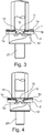
- FIG. 1 shows a first workpiece layer 1 and to be joined to this second material layer 2, which are introduced and positioned in a joining device.
- the joining device known per se comprises a die 21, a lower holder 24 and a punch 26.
- the first workpiece layer 1 consists of a fiber-reinforced material, in the matrix 1a of which a multiplicity of fibers 1b are introduced for reinforcing the matrix material 1a.
- this fiber-reinforced material is a glass or carbon fiber reinforced plastic with aligned long fibers.
- the second material layer 2 consists of a metallic material, in particular of a steel alloy, aluminum alloy or magnesium alloy.
- the second material layer 2 rests on the die 21. On the second material layer 2 lies flat on the first material layer 1.
- the two material layers 1, 2 are fixed by means of the blank holder 24 relative to each other in the joining device.
- a connecting element in the form of a punch rivet 10 is positioned in the joining device above the joint.
- the punch rivet 10 is designed as Halbhohlstanzniet, but could also be a full rivet in a modified version.
- the punch rivet 1 comprises a rivet head 11 and a rivet shank 12.
- the rivet shank 12 is provided with a coating 15, which preferably consists of a polymer which is applied to the rivet shank 12 as an adhesive or plastic.
- FIG. 2 the joint is shown immediately after the combined punching and forming process, in which the punched rivet 10, which is subjected to force by means of the punch 26, is punched through the first workpiece layer 1 and introduced into the second workpiece layer 2.
- the punch rivet 10 serves as a disposable cutting punch and is itself also transformed by being spread by the force applied by the die 21 counterforce on a molding in the die 21. In the present case, this happens in particular without completely piercing the second workpiece layer 2.
- a peripheral, cylindrical cut surface is created due to the punching.
- the matrix material of the matrix 1a and the fibers 1b are cut through in the region of the cut surface. In the edge zone of the cut surface, the fiber ends of the fibers 1b are open and are not covered and protected by matrix material of the matrix 1a. This results in delamination of fibers 1b and matrix material 1a in the cut surface.
- the first workpiece layer 1 is pre-punched before the beginning of the method according to the invention, so that the cut surface in the first workpiece position is not or only partially generated by the punch rivet 10.
- the joint is heated by the punch 26 by the punch 26 is heated and is heated, in particular electrically or inductively.
- the die 21 and / or the hold-down device 24 can also be heated.
- the coating 15 of the rivet shank 12 of the punch rivet 10 melts due to the introduced heat and wets the cut surface in the first workpiece layer 1, so that the coating in particular completely closes the cut surface.
- FIG. 4 shows, the joint is cooled by the heat input is turned off in the punch 26 and in particular additionally actively cooled.
- the punch 26 is already removed from the joint.
- the coating 15 now solidifies on the cut surface of the first workpiece layer 1 and thus covers the fiber ends of the fibers 1b, which are thereby protected from delamination.
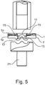
- the joined workpiece layers 1 and 2 are removed from the joining apparatus in a last method step ( FIG. 5 ).
Description
Die Erfindung betrifft ein Verfahren zum Fügen mindestens zweier Werkstücklagen durch Einbringen eines Verbindungselementes mit einer außen auf dem Verbindungselement aufgebrachten Beschichtung, wobei das Verbindungselement mittels einer Fügevorrichtung an einer Fügestelle eingebracht wird und die mindestens zwei Werkstücklagen miteinander verbindet, indem das Verbindungselement aus Richtung der ersten Werkstücklage mittels eines Stempels unter Aufbringung einer Stempelkraft zumindest durch die erste Werkstücklage, unter Bildung einer Schnittfläche in der ersten Werkstücklage oder vorbei an einer Schnittfläche der ersten Werkstücklage, durchgeführt, insbesondere durchgestanzt wird und in die zweite Werkstücklage wenigstens teilweise eindringt und das Verbindungselement mittels einer an der zweiten Werkstücklage anliegenden Matrize unter Aufbringung der Stempelkraft auf das Verbindungselement umgeformt wird, so dass es die mindestens zwei Werkstücklagen formschlüssig miteinander verbindet.The invention relates to a method for joining at least two workpiece layers by introducing a connecting element with a coating applied externally on the connecting element, wherein the connecting element is introduced by means of a joining device at a joint and connects the at least two workpiece layers by the connecting element from the direction of the first workpiece position by means of a punch under application of a punching force at least through the first workpiece layer, to form a cut surface in the first workpiece layer or past a cut surface of the first workpiece layer, carried out, in particular punched and at least partially penetrates into the second workpiece position and the connecting element by means of a on the second die position adjacent die is deformed under application of the stamping force on the connecting element, so that it mi the form-locking mi the at least two workpiece layers connects with each other.
Zum Fügen mindestens zweier Werkstücklagen ist beispielsweise das Stanznietverfahren allgemein bekannt. Dieses Verfahren dient zum unlösbaren kraft- und formschlüssigen Fügen der Werkstücklagen mit speziellen Stanznieten als Verbindungselementen, mit denen die Werkstücklagen ohne vorheriges Lochen in einem kombinierten Stanz- und Umformvorgang durchgestanzt und gefügt werden. Der Stanzniet dient dabei als Einweg-Schneidstempel und wird dabei auch selbst umgeformt. Die Werkstücklagen werden zunächst mittels eines Niederhalters über einer Matrize positioniert. Anschließend wird der Stanzniet über einen Stempel mit einer Kraft beaufschlagt und in die Fügeteile gepresst. Der Nietschaft durchschneidet dabei je nach Nietverfahren zumindest die obersten Werkstücklagen und wird dann in der Matrize aufgespreizt. Bei Verwendung eines Hohlniets geschieht dies insbesondere ohne die unterste Werkstücklage vollständig zu durchstoßen. Beim Stanznieten von faserverstärkten Materialen, wie beispielsweise glasfaser- oder kohlefaserverstärkten Kunststoffen, werden durch den Stanzniet die Fasern durchgeschnitten, und es kann in der Randzone der Schnittfläche zu einer Delaminierung von Fasern und Matrixwerkstoff kommen. Dies kann zu Rissen im Werkstück und einem vollständigen Versagen der Verbindungsstelle führen.For joining at least two workpiece layers, for example, the punch riveting method is generally known. This method is used for permanent and non-positive joining of the workpiece layers with special punch rivets as connecting elements with which the workpiece layers are punched and joined without prior punching in a combined punching and forming process. The punch rivet serves as a disposable cutting punch and is thereby also transformed itself. The workpiece layers are first of all by means of a hold-down over a die positioned. Subsequently, the punch rivet is acted upon by a punch with a force and pressed into the joining parts. Depending on the riveting method, the rivet shank cuts through at least the uppermost workpiece layers and is then spread open in the die. When using a hollow rivet, this is done in particular without completely piercing the lowermost workpiece position. In the case of punched riveting of fiber-reinforced materials, such as for example glass fiber or carbon fiber reinforced plastics, the punch rivet cuts through the fibers and delamination of fibers and matrix material can occur in the edge zone of the cut surface. This can lead to cracks in the workpiece and a complete failure of the joint.
Aus der
Die
Aus der
Aus der gattungsgemäßen
Der Erfindung liegt die Aufgabe zu Grunde, ein Verfahren zum Fügen der eingangs genannten Art zu verbessern, insbesondere um ein Delaminieren von faserverstärkten Werkstücklagen im Bereich der Schnittflächen weitgehend oder vollständig zu vermeiden. Des Weiteren soll ein Verbindungselement und eine Fügevorrichtung zur Durchführung des erfindungsgemäßen Verfahrens zur Verfügung gestellt werden.The invention is based on the object to improve a method for joining the aforementioned type, in particular to largely or completely avoid delamination of fiber-reinforced workpiece layers in the region of the cut surfaces. Furthermore, a connecting element and a joining device for carrying out the method according to the invention are to be made available.
Diese Aufgabe wird erfindungsgemäß durch ein Verfahren mit den im Anspruch 1 genannten Verfahrensschritten gelöst. Vorteilhafte Ausgestaltungen, welche einzeln oder in Kombination miteinander eingesetzt werden können, sind Gegenstand der Unteransprüche.This object is achieved by a method with the method steps mentioned in
Dadurch, dass das Verbindungselement soweit aufgeheizt wird, dass eine Beschichtung des Verbindungselementes schmilzt und die Schnittfläche in der ersten Werkstücklage benetzt, insbesondere vollständig verschließt und dass nach einem Abkühlprozess die wieder verfestigte Beschichtung an der Schnittfläche der ersten Werkstücklage haftet, wird die Schnittfläche durch die Beschichtung insbesondere vollständig verschlossen und dadurch bei Werkstücklagen aus faserverstärktem Kunststoff einer Delaminierung vorgebeugt.Characterized in that the connecting element is heated to the extent that a coating of the connecting element melts and wets the cut surface in the first workpiece layer, in particular completely closes and that after a cooling process, the re-solidified coating adheres to the cut surface of the first workpiece layer, the cut surface is through the coating especially completely closed and thus prevented delamination at workpiece layers made of fiber-reinforced plastic.
Eine oder mehrere der Werkstücklagen können vorgelocht sein, so dass eine durch das Vorlochen entstandene Schnittfläche mittels der Beschichtung bedeckt wird. Die Schnittfläche kann jedoch auch während des erfindungsgemäßen Verfahrens durch das Verbindungselement selbst erzeugt werden. Dazu sind insbesondere durchstanzende Verbindungselemente geeignet.One or more of the workpiece layers may be pre-punched so that a cut surface resulting from the pre-punching is covered by the coating. However, the cut surface can also be generated during the process according to the invention by the connecting element itself. For this purpose, in particular punched connecting elements are suitable.
Unter einem durchstanzenden Verbindungselement ist ein Verbindungselement zu verstehen, das eine oder mehrere Werkstücklagen während des Fügevorgangs durchstanzen kann, d.h. ein Stanzniet. Ein durchstanzendes Verbindungselement aber auch problemlos durch ein zuvor eingebrachtes Vorloch in einer oder in mehreren der Werkstücklagen durchgeführt werden, so dass das Verbindungselement selbst kein Loch in die Werkstücklagen stanzt, sondern im Wesentlichen nur der Verbindung der Werkstücklagen dient. Vorteilhafterweise ist zumindest eine der mindestens zwei Werkstücklagen, insbesondere die erste Werkstücklage, vor Beginn des Verfahrens im Bereich der Fügestelle eine durchgehend geschlossene Fläche ohne Vorloch. Somit wird der Bearbeitungsaufwand reduziert.A piercing connection element is to be understood as meaning a connection element which can pierce one or more workpiece layers during the joining operation, i. a punch rivet. However, a punching connection element can also be carried out without difficulty by a previously introduced pre-hole in one or more of the workpiece layers, so that the connection element itself does not punch a hole in the workpiece layers, but essentially serves only to join the workpiece layers. Advantageously, at least one of the at least two workpiece layers, in particular the first workpiece layer, before the start of the method in the region of the joint is a continuously closed surface without a pre-hole. Thus, the processing cost is reduced.
Besonders geeignet sind Stanzniete, insbesondere Halbhohlstanzniete als durchstanzende Verbindungselemente. Die unterste Werkstücklage (bei zwei Werkstücklagen somit die zweite Werkstücklage) wird vorzugsweise durch den Stanzniet nicht oder nicht vollständig durchgestanzt, so dass eine dichte Fügestelle entsteht. Folglich sind unter dem Oberbegriff "durchstanzendes Verbindungselement" auch bekannte Verbindungselemente zu verstehen, die nicht sämtliche Werkstücklagen vollständig durchstanzen, sondern eine Werkstücklage, insbesondere die zweite von zwei Werkstücklagen, nicht oder nur teilweise durchgestanzt wird. Das Verfahren ist auch unter Verwendung von Vollstanznieten vorteilhaft, insbesondere dann, wenn sämtliche Werkstücklagen vollständig durchstanzt werden.Punch rivets, in particular semi-hollow punch rivets as punched connecting elements, are particularly suitable. The lowermost workpiece layer (thus the second workpiece layer in the case of two workpiece layers) is preferably not or not completely punched through the stamped rivet, so that a tight joint is formed. Consequently, the generic term "punching connection element" is also to be understood as meaning known connection elements which do not completely punch through all of the workpiece layers, but instead of or only partially puncturing a workpiece layer, in particular the second of two workpiece layers. The method is also advantageous using solid rivets, especially when all workpiece layers are completely punched.
Indem das Verbindungselement ein Durchgangsloch oder ein Gewindeloch aufweist, können weitere Funktionen in die Fügestelle integriert oder an der Fügestelle angebunden werden.By the connecting element has a through hole or a threaded hole, more functions can be integrated into the joint or tied at the joint.
Besonders vorteilhaft ist das Verfahren zur Erzeugung von Composits, deren erste Werkstücklage aus einem faserverstärkten Kunststoff besteht, und deren zweite Werkstücklage aus einem metallischem Werkstoff, insbesondere einer Stahllegierung, Aluminiumlegierung oder Magnesiumlegierung besteht.Particularly advantageous is the method for producing composites, the first workpiece layer consists of a fiber-reinforced plastic, and the second workpiece layer consists of a metallic material, in particular a steel alloy, aluminum alloy or magnesium alloy.
Die Beschichtung des Verbindungselements weist bevorzugt einen Kleber oder Kunststoff, insbesondere einen Polymerwerkstoff, auf. Für Stanzniete ist es ausreichend, wenn deren Nietschaft beschichtet ist.The coating of the connecting element preferably has an adhesive or plastic, in particular a polymer material. For punch rivets it is sufficient if their rivet shank is coated.
Je nach Geometrie und Werkstoff der zu fügenden Werkstücklagen kann es vorteilhaft sein, in einem vorgeschalteten Verfahrensschritt eine oder sämtliche Werkstücklagen oder den Stanzniet oder die Fügevorrichtung vorzuwärmen.Depending on the geometry and material of the workpiece layers to be joined, it may be advantageous to preheat one or all workpiece layers or the punch rivet or the joining device in an upstream method step.
Besonders geeignet sind Fügevorrichtungen, die als Werkzeugelemente eine Matrize, einen Niederhalter und einen Stempel umfassen, von denen mindestens ein Werkzeugelement beheizbar ist. Vorzugsweise ist der Stempel beheizbar.Particularly suitable joining devices, which comprise a die, a hold-down and a die as tool elements, of which at least one tool element is heatable. Preferably, the stamp is heatable.
Eine thermische Beschädigung der Werkstücklagen durch zu hohe Temperaturen wird vermieden, indem die Fügevorrichtung eine Temperaturregelungsvorrichtung umfasst, mittels derer die Temperatur des Werkzeugelementes, insbesondere des Stempels, eingestellt und auf einem konstanten Niveau gehalten werden kann.A thermal damage to the workpiece layers due to excessive temperatures is avoided by the joining device comprises a temperature control device by means of which the temperature of the tool element, in particular of the punch, can be adjusted and maintained at a constant level.
Im Folgenden ist die Erfindung anhand eines in den Zeichnungen dargestellten vorteilhaften Ausführungsbeispiels näher erläutert. Die Erfindung ist jedoch nicht auf dieses Ausführungsbeispiele beschränkt. Es zeigen:
-
Fig. 1 zwei zwischen Niederhalter und Matrize positionierte Werkstücklagen vordem Einbringen des Stanzniets, -
Fig. 2 die Fügestelle unmittelbar nach dem Einbringen des Stanzniets in die Fügestelle, -
Fig. 3 das anschließende Aufheizen des Stanzniets und Aufschmelzen der Nietbeschichtung, -
Fig. 4 das anschließende Abkühlen der Fügestelle mit an den Schnittflächen anhaftender Beschichtung und -
Fig. 5 die fertiggestellte Fügestelle unmittelbar vor der Entfernung aus dem Fügevorrichtung.
-
Fig. 1 two workpiece layers positioned between the hold-down device and the die prior to insertion of the punched rivet, -
Fig. 2 the joint immediately after insertion of the punch rivet into the joint, -
Fig. 3 the subsequent heating of the punch rivet and melting of the rivet coating, -
Fig. 4 the subsequent cooling of the joint with adhering to the cut surfaces coating and -
Fig. 5 the finished joint immediately before removal from the joining device.
Die erste Werkstücklage 1 besteht aus einem faserverstärkten Werkstoff, in dessen Matrix 1a eine Vielzahl von Fasern 1b zur Verstärkung des Matrixwerkstoffes 1a eingebracht sind. Bei diesem faserverstärkten Werkstoff handelt es sich vorliegend um einen glas- oder kohlefaserverstärkten Kunststoff mit ausgerichteten Langfasern. Es ist jedoch grundsätzlich der Einsatz aller bekannten faserverstärkten Werkstoffe für die erste Werkstücklage 1 möglich. Die zweite Werkstofflage 2 besteht vorliegend aus einem metallischem Werkstoff, insbesondere aus einer Stahllegierung, Aluminiumlegierung oder Magnesiumlegierung. Es ist jedoch grundsätzlich auch der Einsatz anderer bekannter nicht faserverstärkter oder faserverstärkten Werkstoffe für die zweite Werkstücklage 2 möglich.The
Die zweite Werkstofflage 2 liegt auf der Matrize 21 auf. Auf der zweiten Werkstofflage 2 liegt flächig die erste Werkstofflage 1 auf. Die beiden Werkstofflagen 1, 2 werden mittels des Niederhalters 24 relativ zueinander in der Fügevorrichtung fixiert.The
Ein Verbindungselement in Form eines Stanznietes 10 ist in der Fügevorrichtung oberhalb der Fügestelle positioniert. Der Stanzniet 10 ist als Halbhohlstanzniet ausgeführt, könnte in abgewandelter Ausführung jedoch auch ein Vollniet sein. Der Stanzniet 1 umfasst einen Nietkopf 11 und einen Nietschaft 12. Der Nietschaft 12 ist mit einer Beschichtung 15 versehen, die bevorzugt aus einem Polymer besteht, der als Kleber oder Kunststoff auf den Nietschaft 12 aufgebracht ist.A connecting element in the form of a
In
In einer Abwandlung des Ausführungsbeispiels ist die erste Werkstücklage 1 bereits vor Beginn des erfindungsgemäßen Verfahrens vorgelocht, so dass die Schnittfläche in der ersten Werkstücklage nicht oder nur teilweise durch den Stanzniet 10 erzeugt wird.In a modification of the embodiment, the
In einem nächsten, in der
In einem anschließenden Schritt, den
Die miteinander gefügten Werkstücklagen 1 und 2 werden in einem letzten Verfahrensschritt aus der Fügevorrichtung entnommen (
- 11
- erste Werkstücklagefirst workpiece position
- 1a1a
- Matrixmatrix
- 1b1b
- Faserfiber
- 22
- zweite Werkstücklagesecond workpiece position
- 1010
- Verbindungselement, StanznietConnecting element, punched rivet
- 1111
- Nietkopfrivet head
- 1212
- Nietschaftrivet
- 1515
- Beschichtungcoating
- 2121
- Matrizedie
- 2424
- NiederhalterStripper plate
- 2626
- Stempelstamp
Claims (8)
- Method for joining at least two workpiece layers (1, 2) by introducing a punch rivet (10) having a coating (15) which is applied to the outside of the punch rivet (10), wherein the punch rivet (10) is introduced into the workpiece layers (1, 2) by means of a joining device (21, 24, 26) at a joint and interconnects the at least two workpiece layers (1, 2), in thata. by means of a stamp (26), the punch rivet (10), from the direction of the first workpiece layer (1) and under exertion of a stamping force, and while forming a cutting face in the first workpiece layer (1) or passing beside a cutting face of the first workpiece layer (1), is guided through, in particular punched through, at least the first workpiece layer (1) and penetrates, at least in part, the second workpiece layer,b. the punch rivet (10), by means of a die plate (21) bearing on the second workpiece layer (2), is deformed under exertion of the stamping force onto the punch rivet (10), such that said connecting element (10), in a form-fitting manner, interconnects the at least two workpiece layers (1, 2),c. the punch rivet (10), during the process, is heated to such an extent that the coating (15) which has been applied to the outside of the punch rivet (10) melts and wets the cutting face in the first workpiece layer (1), andd. the re-solidified coating (15), after a cooling process, adheres to the cutting face of the first workpiece layer (1), characterized in that at least one of the at least two workpiece layers (1, 2) is composed of fiber-reinforced plastic.
- Method according to Claim 1, characterized in that the punch rivet (10) is heated to such an extent that the coating (15) melts and completely seals the cutting face in the first workpiece layer (1).
- Method according to Claim 1 or 2, characterized in that, prior to commencing the method, at least one of the at least two workpiece layers (1, 2), in the region of the joint, has a continuously closed surface without a prepunch.
- Method according to Claim 3, characterized in that the through-punching punch rivet (10) is a semi-hollow punch rivet or a solid punch rivet.
- Method according to one of the preceding claims, characterized in that the punch rivet (10) has a through hole or a tapped hole.
- Method according to one of the preceding claims, characterized in that at least one of the at least two workpiece layers (1, 2) is composed of a metallic material, in particular a ferrous alloy, an aluminum alloy, or a magnesium alloy.
- Method according to one of the preceding claims, characterized in that the coating (15) comprises an adhesive or a plastic, in particular a polymer material.
- Method according to Claim 7, characterized in that the coating (15) is composed of a thermoplastic.
Applications Claiming Priority (3)
| Application Number | Priority Date | Filing Date | Title |
|---|---|---|---|
| DE102012006631 | 2012-03-31 | ||
| DE102012008798.5A DE102012008798B4 (en) | 2012-03-31 | 2012-04-19 | Method of joining and connecting element |
| PCT/EP2013/055430 WO2013143887A1 (en) | 2012-03-31 | 2013-03-15 | Method for joining workpiece layers and connecting element and joining device |
Publications (2)
| Publication Number | Publication Date |
|---|---|
| EP2830790A1 EP2830790A1 (en) | 2015-02-04 |
| EP2830790B1 true EP2830790B1 (en) | 2018-06-13 |
Family
ID=49154518
Family Applications (1)
| Application Number | Title | Priority Date | Filing Date |
|---|---|---|---|
| EP13711010.2A Not-in-force EP2830790B1 (en) | 2012-03-31 | 2013-03-15 | Method for joining workpiece layers |
Country Status (8)
| Country | Link |
|---|---|
| US (1) | US20140331478A1 (en) |
| EP (1) | EP2830790B1 (en) |
| JP (1) | JP5847321B2 (en) |
| KR (1) | KR20140102299A (en) |
| CN (1) | CN104023869B (en) |
| DE (1) | DE102012008798B4 (en) |
| IN (1) | IN2014DN03080A (en) |
| WO (1) | WO2013143887A1 (en) |
Families Citing this family (17)
| Publication number | Priority date | Publication date | Assignee | Title |
|---|---|---|---|---|
| DE102014000624B4 (en) * | 2014-01-18 | 2016-07-28 | Audi Ag | Method for joining at least two joining parts, which are overlapping at least in a joining zone, using a padding element |
| US10189113B2 (en) * | 2014-04-24 | 2019-01-29 | GM Global Technology Operations LLC | Resistance spot welding method |
| DE102015207052A1 (en) * | 2015-04-17 | 2016-10-20 | Ejot Gmbh & Co. Kg | Connecting element for positive connection with at least one component |
| DE102015109255A1 (en) * | 2015-06-11 | 2016-12-15 | Profil Verbindungstechnik Gmbh & Co. Kg | Method for fastening a rivet element and corresponding fastening system |
| DE102015016912B3 (en) * | 2015-12-23 | 2017-03-02 | Technische Universität Chemnitz | Tool for producing mechanical joints of overlapping plate-shaped workpieces and mechanical joint connection |
| DE102016118109A1 (en) | 2016-09-26 | 2018-03-29 | Newfrey Llc | Joining method for pre-hole-free connection of at least one first component with a second component |
| US10487863B2 (en) * | 2017-02-17 | 2019-11-26 | Ford Global Technologies, Llc | Castellated joint for improved adhesive coverage when using mechanical fixings and adhesive in one joint |
| CN108296369A (en) * | 2018-01-30 | 2018-07-20 | 芜湖东光奥威汽车制动系统有限公司 | A kind of closing-up machine improving productive temp |
| JP7398186B2 (en) * | 2018-05-10 | 2023-12-14 | 日産自動車株式会社 | Board joining structure and joining method |
| CN108555219B (en) * | 2018-05-14 | 2019-12-31 | 上海应用技术大学 | Self-piercing riveting device and self-piercing riveting method for semi-hollow rivet |
| CN109047620B (en) * | 2018-09-28 | 2024-04-02 | 无锡安士达五金有限公司 | Self-punching rivet |
| KR102081744B1 (en) | 2018-10-02 | 2020-02-26 | 주식회사 성우하이텍 | hybrid jointing apparatus and method for manufacturing joint structure using the same |
| KR102081742B1 (en) | 2018-10-02 | 2020-02-26 | 주식회사 성우하이텍 | hybrid jointing apparatus and method for manufacturing joint structure using the same |
| KR102081737B1 (en) | 2018-10-02 | 2020-02-26 | 주식회사 성우하이텍 | hybrid jointing apparatus and method for manufacturing joint structure using the same |
| KR102161128B1 (en) * | 2018-12-27 | 2020-09-29 | (주)탑아이엔디 | Vehicle body assembly jig |
| US11665755B2 (en) | 2020-05-15 | 2023-05-30 | Zhenbang Yang | Peer-to-peer communication among end user devices |
| CN112659571A (en) * | 2021-03-15 | 2021-04-16 | 长沙理工大学 | Riveting method of carbon fiber plate |
Citations (2)
| Publication number | Priority date | Publication date | Assignee | Title |
|---|---|---|---|---|
| JP2004360746A (en) * | 2003-06-03 | 2004-12-24 | Nissan Motor Co Ltd | Rivet, and junction method using rivet |
| JP2005321018A (en) * | 2004-05-10 | 2005-11-17 | Nissan Motor Co Ltd | Rivet and joining method using rivet |
Family Cites Families (38)
| Publication number | Priority date | Publication date | Assignee | Title |
|---|---|---|---|---|
| US1872385A (en) * | 1930-04-02 | 1932-08-16 | Smith Corp A O | Connecting parts |
| US3524042A (en) * | 1967-02-17 | 1970-08-11 | Gen Electric | Method of making mechanical and welded joint |
| US3639137A (en) * | 1969-10-09 | 1972-02-01 | Ncr Co | Metal fastening coated with pressure-activatable encapsulated sealant system |
| US3878356A (en) * | 1973-09-27 | 1975-04-15 | Cleveland E Roye | Diffusion band riveting method |
| US4010519A (en) * | 1975-11-24 | 1977-03-08 | Shur-Lok Corporation | Fastener structures utilizing a thermoplastic adhesive |
| US4475389A (en) * | 1982-08-23 | 1984-10-09 | Stant Inc. | Radiator cap probe |
| US4838813A (en) * | 1988-05-10 | 1989-06-13 | Amp Incorporated | Terminator plug with electrical resistor |
| US5025128A (en) * | 1988-12-02 | 1991-06-18 | Metcal, Inc. | Rivet with integral heater |
| BR9206821A (en) * | 1991-11-27 | 1995-12-12 | Henrob Ltd | Improved methods of panel tamping |
| US5253965A (en) * | 1992-04-13 | 1993-10-19 | Progressive Tool & Industries Co. | Piercing fastener with adhesive |
| US5680690A (en) * | 1996-02-06 | 1997-10-28 | Franklin S. Briles | Coated rivet and deformation thereof |
| US7131807B1 (en) * | 1999-07-09 | 2006-11-07 | Profil Verbindungstechnik Gmbh & Co., Kg | Functional element, method for fixing it in a sheet metal part, assembling element and swaging assembly |
| DE10125559A1 (en) * | 2001-05-23 | 2002-11-28 | Basf Ag | Composite component manufacturing method, involves compression of a punched edge on a metal component into a plastic component to form a connection |
| JP2003106316A (en) * | 2001-09-28 | 2003-04-09 | Fukui Byora Co Ltd | Self boring rivet, quality-inspecting apparatus for connecting state thereof, and rivet setter provided therewith |
| DE10149633A1 (en) * | 2001-10-09 | 2003-04-10 | Basf Ag | Laminar component composed of metal and plastics sections, is produced by injection moldings and by using stamping edge or collar |
| US6694597B2 (en) * | 2002-03-08 | 2004-02-24 | General Motors Corporation | Method for riveting metal members |
| US6732420B2 (en) * | 2002-03-08 | 2004-05-11 | General Motors Corporation | Method for riveting metal members therewith |
| US6851186B2 (en) * | 2002-11-13 | 2005-02-08 | Malico, Inc. | Environmental protection concerned method for manufacturing heat sink |
| US6836948B2 (en) * | 2003-02-05 | 2005-01-04 | General Motors Corporation | Method of joining a sheet metal part to a metal tube |
| US6905295B2 (en) * | 2003-07-22 | 2005-06-14 | General Motors Corporation | Blind rivet with extended adhesive reservoir |
| JP2005069451A (en) * | 2003-08-28 | 2005-03-17 | Honda Motor Co Ltd | Tightening method for overlapped fiber reinforced plastic plates and its tightening structure |
| US7267736B2 (en) * | 2003-12-18 | 2007-09-11 | General Motors Corporation | Method of joining dissimilar materials |
| DE102004003909B4 (en) * | 2004-01-27 | 2010-09-09 | GM Global Technology Operations, Inc., Detroit | Press welding process for joining two or more sheets or profile parts, in particular a body segment, its use and body segment |
| DE102004025492A1 (en) * | 2004-05-21 | 2009-08-06 | Volkswagen Ag | Method for joining surface materials by using a joining element such as bolts or nuts, comprises welding the joining element with the surface material under mechanical load by resistance heating or inductive heating |
| JP2006043769A (en) * | 2004-07-05 | 2006-02-16 | Nissan Motor Co Ltd | Joining method with self-piercing rivet, and self-piercing rivet joining apparatus |
| DE102005031917A1 (en) | 2004-09-24 | 2006-04-13 | Böllhoff Verbindungstechnik GmbH | Method for joining and device for actuating a joining tool |
| US20080149256A1 (en) * | 2006-12-21 | 2008-06-26 | Gm Global Technology Operations, Inc. | Method and apparatus to minimize adhesive induced distortion |
| JP2008221947A (en) * | 2007-03-09 | 2008-09-25 | Mazda Motor Corp | Vehicle body joining method and its joining structure |
| DE102007030806A1 (en) * | 2007-07-03 | 2009-01-08 | Ejot Gmbh & Co. Kg | Friction welding connection of several superimposed plates |
| DE102007044635A1 (en) * | 2007-09-19 | 2009-04-02 | Böllhoff Verbindungstechnik GmbH | Self-piercing element |
| US8393068B2 (en) * | 2007-11-06 | 2013-03-12 | The Boeing Company | Method and apparatus for assembling composite structures |
| JP5055104B2 (en) * | 2007-12-18 | 2012-10-24 | 日産自動車株式会社 | Self-piercing rivet joining method and rivet joining die |
| US8087149B2 (en) * | 2008-10-09 | 2012-01-03 | GM Global Technology Operations LLC | Self-piercing rivet and method of joining with bonded riveted joints |
| JP2010188383A (en) * | 2009-02-18 | 2010-09-02 | Honda Motor Co Ltd | Rivet joining method |
| US7984919B2 (en) * | 2009-05-18 | 2011-07-26 | Zephyros, Inc. | Structural mounting insert having a non-conductive isolator |
| EP2650105A4 (en) * | 2010-12-08 | 2013-12-04 | Toyota Motor Co Ltd | Method of connecting members |
| CN102248112B (en) * | 2011-06-10 | 2013-07-10 | 郑州大学 | Stirring friction riveting device and method for light metal plate |
| US20140223641A1 (en) * | 2013-02-10 | 2014-08-14 | Blake Henderson | Helmet with custom foam liner and removable / replaceable layers of crushable energy absorption material |
-
2012
- 2012-04-19 DE DE102012008798.5A patent/DE102012008798B4/en not_active Expired - Fee Related
-
2013
- 2013-03-15 IN IN3080DEN2014 patent/IN2014DN03080A/en unknown
- 2013-03-15 CN CN201380004562.7A patent/CN104023869B/en not_active Expired - Fee Related
- 2013-03-15 WO PCT/EP2013/055430 patent/WO2013143887A1/en active Application Filing
- 2013-03-15 JP JP2014540523A patent/JP5847321B2/en not_active Expired - Fee Related
- 2013-03-15 US US14/361,457 patent/US20140331478A1/en not_active Abandoned
- 2013-03-15 KR KR1020147019368A patent/KR20140102299A/en not_active Application Discontinuation
- 2013-03-15 EP EP13711010.2A patent/EP2830790B1/en not_active Not-in-force
Patent Citations (2)
| Publication number | Priority date | Publication date | Assignee | Title |
|---|---|---|---|---|
| JP2004360746A (en) * | 2003-06-03 | 2004-12-24 | Nissan Motor Co Ltd | Rivet, and junction method using rivet |
| JP2005321018A (en) * | 2004-05-10 | 2005-11-17 | Nissan Motor Co Ltd | Rivet and joining method using rivet |
Also Published As
| Publication number | Publication date |
|---|---|
| JP5847321B2 (en) | 2016-01-20 |
| WO2013143887A1 (en) | 2013-10-03 |
| EP2830790A1 (en) | 2015-02-04 |
| CN104023869A (en) | 2014-09-03 |
| KR20140102299A (en) | 2014-08-21 |
| DE102012008798A1 (en) | 2013-10-02 |
| US20140331478A1 (en) | 2014-11-13 |
| CN104023869B (en) | 2016-07-13 |
| JP2014533203A (en) | 2014-12-11 |
| DE102012008798B4 (en) | 2016-01-14 |
| IN2014DN03080A (en) | 2015-05-15 |
Similar Documents
| Publication | Publication Date | Title |
|---|---|---|
| EP2830790B1 (en) | Method for joining workpiece layers | |
| EP3116705B1 (en) | Method for connecting components one of which is made of a fiber-reinforced plastic material | |
| DE19630488C2 (en) | Method and device for joining by forming | |
| EP1790462B1 (en) | Process for joining a metallic bolt to a plastic workpiece | |
| DE102010047032A1 (en) | Method for connecting two metallic elements and connecting tool | |
| DE102015106563B4 (en) | Method for connecting fiber-reinforced structural components | |
| EP2739427A1 (en) | Joining sheet metal-type components having an intermediate layer made of thermoplastic synthetic material | |
| DE102014211222A1 (en) | Method for producing a joint connection by setting and hot pressing a joining element, as well as hereby produced workpiece composite | |
| DE102011114306A1 (en) | Method for joining two fiber-reinforced plastic components by metallic joining element, involves driving setting bolt through fiber-reinforced plastic-components as joint element and subsequently through metal sheet lying in joint area | |
| DE102010020569A1 (en) | Thermally joining first component with second component by electrical heating, comprises provisioning joining auxiliary agent at joining position of component, and melting joining auxiliary agent and second component by electrical heating | |
| DE102014007330A1 (en) | Semi-hollow punching rivet and method for producing a joint connection | |
| DE102015118058A1 (en) | New joining technology for mixed connections | |
| DE102015210965A1 (en) | Method for producing a component composite with a connecting element | |
| WO2015135712A1 (en) | Method for joining a steel part to a fiber-reinforced plastic part by means of a connection element | |
| DE102016001401A1 (en) | Method and device for producing connecting regions on fiber-matrix composite components | |
| DE102014000624B4 (en) | Method for joining at least two joining parts, which are overlapping at least in a joining zone, using a padding element | |
| EP3450141A1 (en) | Method and system for connecting two aircraft components made of a thermoplastic composite material | |
| DE102016200357B4 (en) | Method for joining at least two components by means of a hardened joining element | |
| DE102017205940A1 (en) | Method for producing a composite component and motor vehicle | |
| DE102007022297A1 (en) | Bonding a steel workpiece to a workpiece of light material comprises heating a joint region of the steel to an annealing temperature and cooling before applying adhesive and deforming both workpieces | |
| EP2638988A1 (en) | Self-piercing rivet and method for joining workpieces using said rivet | |
| DE10124920A1 (en) | Riveting method e.g. for automobile body panels, uses sonotrode for oscillation of rivet at defined frequency | |
| DE102009021850A1 (en) | Method for joining workpieces comprises holding a rotating tool in an axially fixed position during melting of one of the workpieces | |
| WO2015161999A1 (en) | Method for the series production of punch rivet connections between frp workpieces and metal workpieces | |
| EP2664394B1 (en) | Method for clinching two ductile components with a non ductile component |
Legal Events
| Date | Code | Title | Description |
|---|---|---|---|
| PUAI | Public reference made under article 153(3) epc to a published international application that has entered the european phase |
Free format text: ORIGINAL CODE: 0009012 |
|
| 17P | Request for examination filed |
Effective date: 20141031 |
|
| AK | Designated contracting states |
Kind code of ref document: A1 Designated state(s): AL AT BE BG CH CY CZ DE DK EE ES FI FR GB GR HR HU IE IS IT LI LT LU LV MC MK MT NL NO PL PT RO RS SE SI SK SM TR |
|
| AX | Request for extension of the european patent |
Extension state: BA ME |
|
| DAX | Request for extension of the european patent (deleted) | ||
| 17Q | First examination report despatched |
Effective date: 20160223 |
|
| RAP1 | Party data changed (applicant data changed or rights of an application transferred) |
Owner name: ADIENT LUXEMBOURG HOLDING S.A R.L. |
|
| STAA | Information on the status of an ep patent application or granted ep patent |
Free format text: STATUS: EXAMINATION IS IN PROGRESS |
|
| GRAP | Despatch of communication of intention to grant a patent |
Free format text: ORIGINAL CODE: EPIDOSNIGR1 |
|
| STAA | Information on the status of an ep patent application or granted ep patent |
Free format text: STATUS: GRANT OF PATENT IS INTENDED |
|
| RAP1 | Party data changed (applicant data changed or rights of an application transferred) |
Owner name: ADIENT LUXEMBOURG HOLDING S.A R.L. |
|
| INTG | Intention to grant announced |
Effective date: 20180226 |
|
| GRAS | Grant fee paid |
Free format text: ORIGINAL CODE: EPIDOSNIGR3 |
|
| GRAA | (expected) grant |
Free format text: ORIGINAL CODE: 0009210 |
|
| STAA | Information on the status of an ep patent application or granted ep patent |
Free format text: STATUS: THE PATENT HAS BEEN GRANTED |
|
| AK | Designated contracting states |
Kind code of ref document: B1 Designated state(s): AL AT BE BG CH CY CZ DE DK EE ES FI FR GB GR HR HU IE IS IT LI LT LU LV MC MK MT NL NO PL PT RO RS SE SI SK SM TR |
|
| REG | Reference to a national code |
Ref country code: GB Ref legal event code: FG4D Free format text: NOT ENGLISH |
|
| REG | Reference to a national code |
Ref country code: CH Ref legal event code: EP Ref country code: AT Ref legal event code: REF Ref document number: 1007942 Country of ref document: AT Kind code of ref document: T Effective date: 20180615 |
|
| REG | Reference to a national code |
Ref country code: IE Ref legal event code: FG4D Free format text: LANGUAGE OF EP DOCUMENT: GERMAN |
|
| REG | Reference to a national code |
Ref country code: DE Ref legal event code: R096 Ref document number: 502013010380 Country of ref document: DE |
|
| REG | Reference to a national code |
Ref country code: NL Ref legal event code: MP Effective date: 20180613 |
|
| REG | Reference to a national code |
Ref country code: LT Ref legal event code: MG4D |
|
| PG25 | Lapsed in a contracting state [announced via postgrant information from national office to epo] |
Ref country code: ES Free format text: LAPSE BECAUSE OF FAILURE TO SUBMIT A TRANSLATION OF THE DESCRIPTION OR TO PAY THE FEE WITHIN THE PRESCRIBED TIME-LIMIT Effective date: 20180613 Ref country code: FI Free format text: LAPSE BECAUSE OF FAILURE TO SUBMIT A TRANSLATION OF THE DESCRIPTION OR TO PAY THE FEE WITHIN THE PRESCRIBED TIME-LIMIT Effective date: 20180613 Ref country code: SE Free format text: LAPSE BECAUSE OF FAILURE TO SUBMIT A TRANSLATION OF THE DESCRIPTION OR TO PAY THE FEE WITHIN THE PRESCRIBED TIME-LIMIT Effective date: 20180613 Ref country code: NO Free format text: LAPSE BECAUSE OF FAILURE TO SUBMIT A TRANSLATION OF THE DESCRIPTION OR TO PAY THE FEE WITHIN THE PRESCRIBED TIME-LIMIT Effective date: 20180913 Ref country code: CY Free format text: LAPSE BECAUSE OF FAILURE TO SUBMIT A TRANSLATION OF THE DESCRIPTION OR TO PAY THE FEE WITHIN THE PRESCRIBED TIME-LIMIT Effective date: 20180613 Ref country code: LT Free format text: LAPSE BECAUSE OF FAILURE TO SUBMIT A TRANSLATION OF THE DESCRIPTION OR TO PAY THE FEE WITHIN THE PRESCRIBED TIME-LIMIT Effective date: 20180613 Ref country code: BG Free format text: LAPSE BECAUSE OF FAILURE TO SUBMIT A TRANSLATION OF THE DESCRIPTION OR TO PAY THE FEE WITHIN THE PRESCRIBED TIME-LIMIT Effective date: 20180913 |
|
| PG25 | Lapsed in a contracting state [announced via postgrant information from national office to epo] |
Ref country code: HR Free format text: LAPSE BECAUSE OF FAILURE TO SUBMIT A TRANSLATION OF THE DESCRIPTION OR TO PAY THE FEE WITHIN THE PRESCRIBED TIME-LIMIT Effective date: 20180613 Ref country code: RS Free format text: LAPSE BECAUSE OF FAILURE TO SUBMIT A TRANSLATION OF THE DESCRIPTION OR TO PAY THE FEE WITHIN THE PRESCRIBED TIME-LIMIT Effective date: 20180613 Ref country code: LV Free format text: LAPSE BECAUSE OF FAILURE TO SUBMIT A TRANSLATION OF THE DESCRIPTION OR TO PAY THE FEE WITHIN THE PRESCRIBED TIME-LIMIT Effective date: 20180613 Ref country code: GR Free format text: LAPSE BECAUSE OF FAILURE TO SUBMIT A TRANSLATION OF THE DESCRIPTION OR TO PAY THE FEE WITHIN THE PRESCRIBED TIME-LIMIT Effective date: 20180914 |
|
| PG25 | Lapsed in a contracting state [announced via postgrant information from national office to epo] |
Ref country code: NL Free format text: LAPSE BECAUSE OF FAILURE TO SUBMIT A TRANSLATION OF THE DESCRIPTION OR TO PAY THE FEE WITHIN THE PRESCRIBED TIME-LIMIT Effective date: 20180613 |
|
| PG25 | Lapsed in a contracting state [announced via postgrant information from national office to epo] |
Ref country code: SK Free format text: LAPSE BECAUSE OF FAILURE TO SUBMIT A TRANSLATION OF THE DESCRIPTION OR TO PAY THE FEE WITHIN THE PRESCRIBED TIME-LIMIT Effective date: 20180613 Ref country code: CZ Free format text: LAPSE BECAUSE OF FAILURE TO SUBMIT A TRANSLATION OF THE DESCRIPTION OR TO PAY THE FEE WITHIN THE PRESCRIBED TIME-LIMIT Effective date: 20180613 Ref country code: RO Free format text: LAPSE BECAUSE OF FAILURE TO SUBMIT A TRANSLATION OF THE DESCRIPTION OR TO PAY THE FEE WITHIN THE PRESCRIBED TIME-LIMIT Effective date: 20180613 Ref country code: EE Free format text: LAPSE BECAUSE OF FAILURE TO SUBMIT A TRANSLATION OF THE DESCRIPTION OR TO PAY THE FEE WITHIN THE PRESCRIBED TIME-LIMIT Effective date: 20180613 Ref country code: IS Free format text: LAPSE BECAUSE OF FAILURE TO SUBMIT A TRANSLATION OF THE DESCRIPTION OR TO PAY THE FEE WITHIN THE PRESCRIBED TIME-LIMIT Effective date: 20181013 Ref country code: PL Free format text: LAPSE BECAUSE OF FAILURE TO SUBMIT A TRANSLATION OF THE DESCRIPTION OR TO PAY THE FEE WITHIN THE PRESCRIBED TIME-LIMIT Effective date: 20180613 |
|
| PG25 | Lapsed in a contracting state [announced via postgrant information from national office to epo] |
Ref country code: SM Free format text: LAPSE BECAUSE OF FAILURE TO SUBMIT A TRANSLATION OF THE DESCRIPTION OR TO PAY THE FEE WITHIN THE PRESCRIBED TIME-LIMIT Effective date: 20180613 Ref country code: IT Free format text: LAPSE BECAUSE OF FAILURE TO SUBMIT A TRANSLATION OF THE DESCRIPTION OR TO PAY THE FEE WITHIN THE PRESCRIBED TIME-LIMIT Effective date: 20180613 |
|
| REG | Reference to a national code |
Ref country code: DE Ref legal event code: R097 Ref document number: 502013010380 Country of ref document: DE |
|
| PLBE | No opposition filed within time limit |
Free format text: ORIGINAL CODE: 0009261 |
|
| STAA | Information on the status of an ep patent application or granted ep patent |
Free format text: STATUS: NO OPPOSITION FILED WITHIN TIME LIMIT |
|
| 26N | No opposition filed |
Effective date: 20190314 |
|
| PG25 | Lapsed in a contracting state [announced via postgrant information from national office to epo] |
Ref country code: DK Free format text: LAPSE BECAUSE OF FAILURE TO SUBMIT A TRANSLATION OF THE DESCRIPTION OR TO PAY THE FEE WITHIN THE PRESCRIBED TIME-LIMIT Effective date: 20180613 Ref country code: SI Free format text: LAPSE BECAUSE OF FAILURE TO SUBMIT A TRANSLATION OF THE DESCRIPTION OR TO PAY THE FEE WITHIN THE PRESCRIBED TIME-LIMIT Effective date: 20180613 |
|
| PG25 | Lapsed in a contracting state [announced via postgrant information from national office to epo] |
Ref country code: MC Free format text: LAPSE BECAUSE OF FAILURE TO SUBMIT A TRANSLATION OF THE DESCRIPTION OR TO PAY THE FEE WITHIN THE PRESCRIBED TIME-LIMIT Effective date: 20180613 |
|
| REG | Reference to a national code |
Ref country code: CH Ref legal event code: PL |
|
| GBPC | Gb: european patent ceased through non-payment of renewal fee |
Effective date: 20190315 |
|
| PG25 | Lapsed in a contracting state [announced via postgrant information from national office to epo] |
Ref country code: AL Free format text: LAPSE BECAUSE OF FAILURE TO SUBMIT A TRANSLATION OF THE DESCRIPTION OR TO PAY THE FEE WITHIN THE PRESCRIBED TIME-LIMIT Effective date: 20180613 Ref country code: LU Free format text: LAPSE BECAUSE OF NON-PAYMENT OF DUE FEES Effective date: 20190315 |
|
| REG | Reference to a national code |
Ref country code: BE Ref legal event code: MM Effective date: 20190331 |
|
| PG25 | Lapsed in a contracting state [announced via postgrant information from national office to epo] |
Ref country code: IE Free format text: LAPSE BECAUSE OF NON-PAYMENT OF DUE FEES Effective date: 20190315 Ref country code: CH Free format text: LAPSE BECAUSE OF NON-PAYMENT OF DUE FEES Effective date: 20190331 Ref country code: GB Free format text: LAPSE BECAUSE OF NON-PAYMENT OF DUE FEES Effective date: 20190315 Ref country code: LI Free format text: LAPSE BECAUSE OF NON-PAYMENT OF DUE FEES Effective date: 20190331 |
|
| PG25 | Lapsed in a contracting state [announced via postgrant information from national office to epo] |
Ref country code: BE Free format text: LAPSE BECAUSE OF NON-PAYMENT OF DUE FEES Effective date: 20190331 |
|
| PG25 | Lapsed in a contracting state [announced via postgrant information from national office to epo] |
Ref country code: TR Free format text: LAPSE BECAUSE OF FAILURE TO SUBMIT A TRANSLATION OF THE DESCRIPTION OR TO PAY THE FEE WITHIN THE PRESCRIBED TIME-LIMIT Effective date: 20180613 |
|
| PG25 | Lapsed in a contracting state [announced via postgrant information from national office to epo] |
Ref country code: PT Free format text: LAPSE BECAUSE OF FAILURE TO SUBMIT A TRANSLATION OF THE DESCRIPTION OR TO PAY THE FEE WITHIN THE PRESCRIBED TIME-LIMIT Effective date: 20181015 Ref country code: MT Free format text: LAPSE BECAUSE OF FAILURE TO SUBMIT A TRANSLATION OF THE DESCRIPTION OR TO PAY THE FEE WITHIN THE PRESCRIBED TIME-LIMIT Effective date: 20180613 |
|
| REG | Reference to a national code |
Ref country code: AT Ref legal event code: MM01 Ref document number: 1007942 Country of ref document: AT Kind code of ref document: T Effective date: 20190315 |
|
| PG25 | Lapsed in a contracting state [announced via postgrant information from national office to epo] |
Ref country code: AT Free format text: LAPSE BECAUSE OF NON-PAYMENT OF DUE FEES Effective date: 20190315 |
|
| PG25 | Lapsed in a contracting state [announced via postgrant information from national office to epo] |
Ref country code: HU Free format text: LAPSE BECAUSE OF FAILURE TO SUBMIT A TRANSLATION OF THE DESCRIPTION OR TO PAY THE FEE WITHIN THE PRESCRIBED TIME-LIMIT; INVALID AB INITIO Effective date: 20130315 |
|
| PGFP | Annual fee paid to national office [announced via postgrant information from national office to epo] |
Ref country code: DE Payment date: 20220329 Year of fee payment: 10 |
|
| PGFP | Annual fee paid to national office [announced via postgrant information from national office to epo] |
Ref country code: FR Payment date: 20220325 Year of fee payment: 10 |
|
| PG25 | Lapsed in a contracting state [announced via postgrant information from national office to epo] |
Ref country code: MK Free format text: LAPSE BECAUSE OF FAILURE TO SUBMIT A TRANSLATION OF THE DESCRIPTION OR TO PAY THE FEE WITHIN THE PRESCRIBED TIME-LIMIT Effective date: 20180613 |
|
| REG | Reference to a national code |
Ref country code: DE Ref legal event code: R081 Ref document number: 502013010380 Country of ref document: DE Owner name: ADIENT US LLC, PLYMOUTH, US Free format text: FORMER OWNER: ADIENT LUXEMBOURG HOLDING S.A R.L., LUXEMBOURG, LU |
|
| REG | Reference to a national code |
Ref country code: DE Ref legal event code: R119 Ref document number: 502013010380 Country of ref document: DE |
|
| PG25 | Lapsed in a contracting state [announced via postgrant information from national office to epo] |
Ref country code: FR Free format text: LAPSE BECAUSE OF NON-PAYMENT OF DUE FEES Effective date: 20230331 Ref country code: DE Free format text: LAPSE BECAUSE OF NON-PAYMENT OF DUE FEES Effective date: 20231003 |