EP2830770B1 - Brake mechanism for an electronic pipette - Google Patents
Brake mechanism for an electronic pipette Download PDFInfo
- Publication number
- EP2830770B1 EP2830770B1 EP13768512.9A EP13768512A EP2830770B1 EP 2830770 B1 EP2830770 B1 EP 2830770B1 EP 13768512 A EP13768512 A EP 13768512A EP 2830770 B1 EP2830770 B1 EP 2830770B1
- Authority
- EP
- European Patent Office
- Prior art keywords
- brake
- movement
- lever
- brake member
- rotor
- Prior art date
- Legal status (The legal status is an assumption and is not a legal conclusion. Google has not performed a legal analysis and makes no representation as to the accuracy of the status listed.)
- Active
Links
Images
Classifications
-
- B—PERFORMING OPERATIONS; TRANSPORTING
- B01—PHYSICAL OR CHEMICAL PROCESSES OR APPARATUS IN GENERAL
- B01L—CHEMICAL OR PHYSICAL LABORATORY APPARATUS FOR GENERAL USE
- B01L3/00—Containers or dishes for laboratory use, e.g. laboratory glassware; Droppers
- B01L3/02—Burettes; Pipettes
- B01L3/021—Pipettes, i.e. with only one conduit for withdrawing and redistributing liquids
-
- B—PERFORMING OPERATIONS; TRANSPORTING
- B01—PHYSICAL OR CHEMICAL PROCESSES OR APPARATUS IN GENERAL
- B01L—CHEMICAL OR PHYSICAL LABORATORY APPARATUS FOR GENERAL USE
- B01L3/00—Containers or dishes for laboratory use, e.g. laboratory glassware; Droppers
- B01L3/02—Burettes; Pipettes
- B01L3/021—Pipettes, i.e. with only one conduit for withdrawing and redistributing liquids
- B01L3/0217—Pipettes, i.e. with only one conduit for withdrawing and redistributing liquids of the plunger pump type
-
- B—PERFORMING OPERATIONS; TRANSPORTING
- B01—PHYSICAL OR CHEMICAL PROCESSES OR APPARATUS IN GENERAL
- B01L—CHEMICAL OR PHYSICAL LABORATORY APPARATUS FOR GENERAL USE
- B01L3/00—Containers or dishes for laboratory use, e.g. laboratory glassware; Droppers
- B01L3/02—Burettes; Pipettes
- B01L3/021—Pipettes, i.e. with only one conduit for withdrawing and redistributing liquids
- B01L3/0217—Pipettes, i.e. with only one conduit for withdrawing and redistributing liquids of the plunger pump type
- B01L3/0227—Details of motor drive means
-
- F—MECHANICAL ENGINEERING; LIGHTING; HEATING; WEAPONS; BLASTING
- F16—ENGINEERING ELEMENTS AND UNITS; GENERAL MEASURES FOR PRODUCING AND MAINTAINING EFFECTIVE FUNCTIONING OF MACHINES OR INSTALLATIONS; THERMAL INSULATION IN GENERAL
- F16D—COUPLINGS FOR TRANSMITTING ROTATION; CLUTCHES; BRAKES
- F16D63/00—Brakes not otherwise provided for; Brakes combining more than one of the types of groups F16D49/00 - F16D61/00
- F16D63/006—Positive locking brakes
-
- H—ELECTRICITY
- H02—GENERATION; CONVERSION OR DISTRIBUTION OF ELECTRIC POWER
- H02P—CONTROL OR REGULATION OF ELECTRIC MOTORS, ELECTRIC GENERATORS OR DYNAMO-ELECTRIC CONVERTERS; CONTROLLING TRANSFORMERS, REACTORS OR CHOKE COILS
- H02P3/00—Arrangements for stopping or slowing electric motors, generators, or dynamo-electric converters
-
- B—PERFORMING OPERATIONS; TRANSPORTING
- B01—PHYSICAL OR CHEMICAL PROCESSES OR APPARATUS IN GENERAL
- B01L—CHEMICAL OR PHYSICAL LABORATORY APPARATUS FOR GENERAL USE
- B01L2200/00—Solutions for specific problems relating to chemical or physical laboratory apparatus
- B01L2200/06—Fluid handling related problems
-
- B—PERFORMING OPERATIONS; TRANSPORTING
- B01—PHYSICAL OR CHEMICAL PROCESSES OR APPARATUS IN GENERAL
- B01L—CHEMICAL OR PHYSICAL LABORATORY APPARATUS FOR GENERAL USE
- B01L2400/00—Moving or stopping fluids
- B01L2400/04—Moving fluids with specific forces or mechanical means
- B01L2400/0475—Moving fluids with specific forces or mechanical means specific mechanical means and fluid pressure
-
- B—PERFORMING OPERATIONS; TRANSPORTING
- B01—PHYSICAL OR CHEMICAL PROCESSES OR APPARATUS IN GENERAL
- B01L—CHEMICAL OR PHYSICAL LABORATORY APPARATUS FOR GENERAL USE
- B01L3/00—Containers or dishes for laboratory use, e.g. laboratory glassware; Droppers
- B01L3/02—Burettes; Pipettes
Definitions
- a pipette according to the present invention solves the above mentioned problems.
- the brake actuator in a pipette according to the invention is used for abrupt stopping of the movement of the actuator that moves the plunger.
- the brake actuator in a pipette according to the invention comprises an electromotive functional member that turns a brake part stopping the rotational movement by means of a mediating mechanism.
- the invention is directed to an electronic pipette comprising a brake mechanism, which mechanism is used for abrupt stopping of the movement of the actuator that moves the plunger.
- the mechanism comprises a rotatable, essentially circular rotor which is provided at its periphery with brake notches arranged at regular intervals, and a brake actuator comprising an actuating member, a brake member to which a brake cam compatible with the brake notches is connected, a mediation mechanism for transmission of the movement of the motion member to the brake member, the brake member comprising a turnable member connected to the motion member that is arranged to act with the brake member such that the movement of the turnable member can be accelerated before it essentially effects the movement of the brake member.
- the brake member comprises an opening in which the turnable member is adapted, here a lever (2) that is turnably adapted on a shaft (2a).
- the shape of the opening is arranged to be such that the turnable member can turn between two locked end positions.
- the turnable member turns about 180° from one end position to the other.
- the size of the opening in relation to the turning lever is such that it enables the turning lever to move between the two positions and that depending of the position of the turning lever in the opening, the turning lever forces the brake member to turn around its axis from a locked position to a free position, and from a free position to a locked position.
- the brake notches of the rotor comprise protrusions for stopping the rotor and slots for locking the rotor in relation to the brake cam.
- the protrusions in the rotor stop the rotor as the brake cam locks into a slot between two protrusions.
- the brake cam ends up in the upper or lower brake notch of figure 3 .
- the drive means can be a DC-motor, a linear solenoid or a rotary solenoid.
- the brake drive means is coupled to the brake member by a mediation mechanism.
- the configuration according to the invention comprising a mediation mechanism has the first advantage of the brake part locking into both end positions.
- a second advantage of the solution according to the invention is the high momentary velocity of the brake part physically stopping the movement, i.e. the turnable member.
- the mediation member between the brake drive means, i.e. the movement-inducing means (the motor), and the brake member enables the brake motor to accelerate before the movement for stopping the brake member rotor begins.
- the turning movement of the turnable member reaches its top speed almost immediately as the movement begins, whereby the brake member hits its target location in the rotating rotor in a more controlled manner.
- the high velocity of the brake member enables, in terms of functionality, a preferred higher velocity of the stopping part at the braking moment.
- a third advantage is that due to the kinetic energy accumulated during the acceleration of the drive means, force is gained in the movement of the brake member in the very beginning of the movement, which leads to more reliable opening and closing of the brake.
- the mediation mechanism functionality according to the invention can be implemented with a crank mechanism or a cam gear mechanism.
- the brake actuator turns approximately 180 degrees in all, and the brake member stopping the movement turns a fraction of this.
- the brake member and the brake actuator are coupled to each other with a connecting rod.
- the brake part reaches its top angular velocity between the two ends of the movement of the brake actuator, the velocity is zero or close to zero at the end positions.
- the actual brake member stopping the rotation movement is moved by a cam gear mechanism that is simpler than a crank mechanism.
- An advantage of the invention over the prior art is also that in the structure according to the invention, the brake locks the rotor into place without any clearance causing a movement error.
- a significant advantage of the structure according to the invention is the ability of the brake to lock into the extreme positions, preventing undesired closing of the brake during running in case of a loss of electricity. This is a very important feature since braking while running at high speed may break the operating mechanism.
- the brake motor turns the brake member back and forth by means of the mediation mechanism.
- the brake member turns about 20°.
- the "barb" of the brake member locks the rotating movement of the rotor and at the other end the rotation is free.
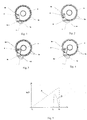
- Figure 1 shows the brake member (1) that is attached to the body of the brake at its pivot pin (1b) such that it can turn.
- the task of the brake cam (1a) of the brake member is to stop the rotation of rotor (3) by setting into a brake notch (3a) of the rotor.
- the turning lever (2) is locked onto the shaft (2a) of the electric motor (not shown) and is so located that at the extreme ends of its movement the brake member is either open or closed.
- the brake is closed and the relative location and the geometry of the brake member and the turning lever locks the brake at the position even though the motor is not powered on.
- FIG. 5 the power generation and speed advantage achieved by the mechanism are illustrated.
- the X-axis represents time and the Y-axis the angular velocity.
- the motor When the motor is turned on at time t1, it accelerates according to graph A.
- Graph B illustrates the angular velocity of the brake part.
- the turning lever hits the brake member at high speed, quickly turning it to its other end position.
- the movement of the parts stops and the brake is locked at the other end position.
- FIG. 5 the power generation and speed advantage achieved by the mechanism are illustrated.
- the X-axis represents time and the Y-axis the angular velocity.
- the motor When the motor is turned on at time t1, it accelerates according to graph A.
- Graph B illustrates the angular velocity of the brake member.
- the turning lever hits the brake member at high speed, quickly turning it to its other end position.
- the movement of the parts stops and the brake is locked at the other end position.
Landscapes
- Engineering & Computer Science (AREA)
- Chemical Kinetics & Catalysis (AREA)
- Health & Medical Sciences (AREA)
- Clinical Laboratory Science (AREA)
- Chemical & Material Sciences (AREA)
- General Engineering & Computer Science (AREA)
- Mechanical Engineering (AREA)
- Power Engineering (AREA)
- Connection Of Motors, Electrical Generators, Mechanical Devices, And The Like (AREA)
- Devices For Use In Laboratory Experiments (AREA)
- Sampling And Sample Adjustment (AREA)
- Transmission Devices (AREA)
- Braking Arrangements (AREA)
Description
- Solutions based on brakeless stepper motors have conventionally been used as an essential part of the operating machinery of electronic pipettes. The combination presented in Finnish patent no.
87740 FI 87740
In Japanese patent applicationH01 210039 A - A pipette according to the present invention solves the above mentioned problems. The brake actuator in a pipette according to the invention is used for abrupt stopping of the movement of the actuator that moves the plunger. The brake actuator in a pipette according to the invention comprises an electromotive functional member that turns a brake part stopping the rotational movement by means of a mediating mechanism.
- The invention is directed to an electronic pipette comprising a brake mechanism, which mechanism is used for abrupt stopping of the movement of the actuator that moves the plunger. The mechanism comprises a rotatable, essentially circular rotor which is provided at its periphery with brake notches arranged at regular intervals, and a brake actuator comprising an actuating member, a brake member to which a brake cam compatible with the brake notches is connected, a mediation mechanism for transmission of the movement of the motion member to the brake member, the brake member comprising a turnable member connected to the motion member that is arranged to act with the brake member such that the movement of the turnable member can be accelerated before it essentially effects the movement of the brake member.
- According to the invention, the brake member comprises an opening in which the turnable member is adapted, here a lever (2) that is turnably adapted on a shaft (2a). The shape of the opening is arranged to be such that the turnable member can turn between two locked end positions. Preferably, the turnable member turns about 180° from one end position to the other. The size of the opening in relation to the turning lever is such that it enables the turning lever to move between the two positions and that depending of the position of the turning lever in the opening, the turning lever forces the brake member to turn around its axis from a locked position to a free position, and from a free position to a locked position.
- According to a preferred embodiment the brake notches of the rotor comprise protrusions for stopping the rotor and slots for locking the rotor in relation to the brake cam. The protrusions in the rotor stop the rotor as the brake cam locks into a slot between two protrusions. Depending on the direction of rotation, the brake cam ends up in the upper or lower brake notch of
figure 3 . When the rotor rotates counter-clockwise, the brake cam locks into the lower notch and when it rotates clockwise in turn into the upper notch. - In the brake configuration according to the invention, the drive means can be a DC-motor, a linear solenoid or a rotary solenoid.
- In the configuration according to the invention the brake drive means is coupled to the brake member by a mediation mechanism. The configuration according to the invention comprising a mediation mechanism has the first advantage of the brake part locking into both end positions. A second advantage of the solution according to the invention is the high momentary velocity of the brake part physically stopping the movement, i.e. the turnable member. The mediation member between the brake drive means, i.e. the movement-inducing means (the motor), and the brake member enables the brake motor to accelerate before the movement for stopping the brake member rotor begins. Thus, the turning movement of the turnable member reaches its top speed almost immediately as the movement begins, whereby the brake member hits its target location in the rotating rotor in a more controlled manner. On the other hand, the high velocity of the brake member enables, in terms of functionality, a preferred higher velocity of the stopping part at the braking moment. A third advantage is that due to the kinetic energy accumulated during the acceleration of the drive means, force is gained in the movement of the brake member in the very beginning of the movement, which leads to more reliable opening and closing of the brake.
- The mediation mechanism functionality according to the invention can be implemented with a crank mechanism or a cam gear mechanism. In both mechanisms the brake actuator turns approximately 180 degrees in all, and the brake member stopping the movement turns a fraction of this. In a cam gear mechanism, the brake member and the brake actuator are coupled to each other with a connecting rod. In this mechanism the brake part reaches its top angular velocity between the two ends of the movement of the brake actuator, the velocity is zero or close to zero at the end positions. According to a preferred embodiment, the actual brake member stopping the rotation movement is moved by a cam gear mechanism that is simpler than a crank mechanism.
- An advantage of the invention over the prior art is also that in the structure according to the invention, the brake locks the rotor into place without any clearance causing a movement error.
- A significant advantage of the structure according to the invention is the ability of the brake to lock into the extreme positions, preventing undesired closing of the brake during running in case of a loss of electricity. This is a very important feature since braking while running at high speed may break the operating mechanism.
- According to the invention the brake motor turns the brake member back and forth by means of the mediation mechanism. In a preferred embodiment the brake member turns about 20°. At one end the "barb" of the brake member locks the rotating movement of the rotor and at the other end the rotation is free.
- In
Figures 1-4 , one technical solution for implementing the function according to the invention is presented.Figure 1 shows the brake member (1) that is attached to the body of the brake at its pivot pin (1b) such that it can turn. The task of the brake cam (1a) of the brake member is to stop the rotation of rotor (3) by setting into a brake notch (3a) of the rotor. The turning lever (2) is locked onto the shaft (2a) of the electric motor (not shown) and is so located that at the extreme ends of its movement the brake member is either open or closed. In the situation infigure 1 , the brake is closed and the relative location and the geometry of the brake member and the turning lever locks the brake at the position even though the motor is not powered on. - In
Figure 2 , the motor is switched on and the turning lever has accelerated freely approximately 90° and is about to hit the brake member. - In the situation of
Figure 3 , the turning lever has turned to its other end position and has at the same time turned the brake member into its open position. Also in this position, the brake is locked into position as infigure 1 . - In
Figure 4 we are in the situation offigure 2 of applying the brake. - In
Figure 5 , the power generation and speed advantage achieved by the mechanism are illustrated. The X-axis represents time and the Y-axis the angular velocity. When the motor is turned on at time t1, it accelerates according to graph A. Graph B illustrates the angular velocity of the brake part. At time t2 the turning lever hits the brake member at high speed, quickly turning it to its other end position. At time t3 the movement of the parts stops and the brake is locked at the other end position. - In
Figure 4 we are in the situation where the turning lever is about to hit the brake member, as infigure 2 , now for closing the brake. - In
Figure 5 , the power generation and speed advantage achieved by the mechanism are illustrated. The X-axis represents time and the Y-axis the angular velocity. When the motor is turned on at time t1, it accelerates according to graph A. Graph B illustrates the angular velocity of the brake member. At time t2 the turning lever hits the brake member at high speed, quickly turning it to its other end position. At time t3 the movement of the parts stops and the brake is locked at the other end position.
Claims (3)
- An electronic pipette comprising a brake mechanism, wherein the mechanism comprises a rotatable, circular rotor (3) that is at its periphery provided with brake notches (3a) arranged at regular intervals, and a brake actuator comprising- a movement-inducing means,- a brake member (1) comprising a brake cam (1a) that is compatible with and settable into the brake notches (3a),- a mediation mechanism for transmission of the movement of the movement-inducing means to the brake member (1),characterized in that the brake member comprises an opening in which a turnable lever (2) is adapted;
the opening in the brake member (1) being such that the lever (2) can turn between two end positions into which the lever (2) is lockable;
wherein the lever (2) is arranged, upon movement within the opening between said two end positions, to force the brake member (1) to turn around a pivot (1b) from a position where the brake cam (1a) locks the rotor (3) to a position where the rotor (3) is free and vice versa. - The pipette according to claim 1, characterized in that the movement-inducing means is an electric motor.
- The pipette according to claim 1 or claim 2, characterized in that
the brake member (1) is turnable by about 20° around the pivot (1b), and
the lever (2) is turnable by about 180° in the opening between said two end positions,
wherein the lever (2) is arranged to hit and turn the brake member (1) at a turning angle of the lever of about 90°.
Applications Claiming Priority (2)
| Application Number | Priority Date | Filing Date | Title |
|---|---|---|---|
| FI20125372A FI125310B (en) | 2012-03-30 | 2012-03-30 | Brake mechanism for electronic pipette |
| PCT/FI2013/050359 WO2013144457A1 (en) | 2012-03-30 | 2013-04-02 | Brake mechanism for an electronic pipette |
Publications (3)
| Publication Number | Publication Date |
|---|---|
| EP2830770A1 EP2830770A1 (en) | 2015-02-04 |
| EP2830770A4 EP2830770A4 (en) | 2015-11-25 |
| EP2830770B1 true EP2830770B1 (en) | 2018-10-10 |
Family
ID=49258316
Family Applications (1)
| Application Number | Title | Priority Date | Filing Date |
|---|---|---|---|
| EP13768512.9A Active EP2830770B1 (en) | 2012-03-30 | 2013-04-02 | Brake mechanism for an electronic pipette |
Country Status (7)
| Country | Link |
|---|---|
| US (1) | US9387473B2 (en) |
| EP (1) | EP2830770B1 (en) |
| JP (1) | JP6268160B2 (en) |
| CN (1) | CN104169005B (en) |
| FI (1) | FI125310B (en) |
| RU (1) | RU2638367C2 (en) |
| WO (1) | WO2013144457A1 (en) |
Families Citing this family (2)
| Publication number | Priority date | Publication date | Assignee | Title |
|---|---|---|---|---|
| US10094161B2 (en) * | 2015-05-15 | 2018-10-09 | Vapensystems Inc. | Weapons storage system and locking mechanism |
| US10876585B2 (en) * | 2017-08-21 | 2020-12-29 | Hall Labs Llc | Parking brake and anti-theft apparatus for vented disc brakes |
Citations (1)
| Publication number | Priority date | Publication date | Assignee | Title |
|---|---|---|---|---|
| JPH01210039A (en) * | 1988-02-19 | 1989-08-23 | Fuji Photo Film Co Ltd | Pipette for partial pipetting |
Family Cites Families (17)
| Publication number | Priority date | Publication date | Assignee | Title |
|---|---|---|---|---|
| US801983A (en) * | 1904-12-16 | 1905-10-17 | Olney James Hubbard | Bale-tying apparatus. |
| SU13622A1 (en) * | 1928-12-21 | 1930-03-31 | А.И. Певзнер | A device for turning the flywheel of internal combustion engines at the start of the course |
| US2175601A (en) * | 1936-12-19 | 1939-10-10 | Grund William | Calking gun |
| US5187990A (en) | 1984-02-16 | 1993-02-23 | Rainin Instrument Co., Inc. | Method for dispensing liquids with a pipette with compensation for air pressure and surface tension |
| FI87740C (en) * | 1990-05-04 | 1994-04-08 | Biohit Oy | Pipette |
| FI961649A0 (en) * | 1996-04-15 | 1996-04-15 | Labsystems Oy | Spaerrpipett |
| WO2000051738A1 (en) * | 1999-03-05 | 2000-09-08 | Rainin Instrument Co., Inc. | Improved battery powered microprocessor controlled hand portable electronic pipette |
| US6254832B1 (en) * | 1999-03-05 | 2001-07-03 | Rainin Instrument Co., Inc. | Battery powered microprocessor controlled hand portable electronic pipette |
| US6532837B1 (en) * | 2000-02-03 | 2003-03-18 | Rainin Instrument, Llc | Pipette device with tip ejector utilizing stored energy |
| US6428750B1 (en) * | 2000-02-17 | 2002-08-06 | Rainin Instrument, Llc | Volume adjustable manual pipette with quick set volume adjustment |
| US6715369B2 (en) * | 2000-08-03 | 2004-04-06 | Nichiryo Co., Ltd. | Hybrid pipette |
| JP3640904B2 (en) * | 2000-08-03 | 2005-04-20 | 株式会社ニチリョー | Hybrid pipette device |
| RU2340397C2 (en) * | 2003-11-27 | 2008-12-10 | Джилсон С.А.С. | Electronic pipette with display and manipulator for controlling liquid suction and distribution |
| US7690293B2 (en) | 2007-01-05 | 2010-04-06 | Ivek Corporation | Coupling system for use with fluid displacement apparatus |
| DE102007006076B4 (en) * | 2007-02-02 | 2008-10-30 | Brand Gmbh + Co Kg | Multichannel pipetting |
| PL211690B1 (en) * | 2007-11-23 | 2012-06-29 | Pz Htl Społka Akcyjna | Pipette with preset volume of collected liquid |
| CN102917795B (en) * | 2010-05-03 | 2014-11-12 | 因特格拉生物科学股份公司 | Manually directed, multi-channel electronic pipetting system |
-
2012
- 2012-03-30 FI FI20125372A patent/FI125310B/en active IP Right Grant
-
2013
- 2013-04-02 RU RU2014143485A patent/RU2638367C2/en active
- 2013-04-02 EP EP13768512.9A patent/EP2830770B1/en active Active
- 2013-04-02 JP JP2015502396A patent/JP6268160B2/en active Active
- 2013-04-02 WO PCT/FI2013/050359 patent/WO2013144457A1/en not_active Ceased
- 2013-04-02 CN CN201380015604.7A patent/CN104169005B/en active Active
- 2013-04-02 US US14/385,710 patent/US9387473B2/en active Active
Patent Citations (1)
| Publication number | Priority date | Publication date | Assignee | Title |
|---|---|---|---|---|
| JPH01210039A (en) * | 1988-02-19 | 1989-08-23 | Fuji Photo Film Co Ltd | Pipette for partial pipetting |
Also Published As
| Publication number | Publication date |
|---|---|
| JP6268160B2 (en) | 2018-01-24 |
| EP2830770A1 (en) | 2015-02-04 |
| CN104169005A (en) | 2014-11-26 |
| JP2015518417A (en) | 2015-07-02 |
| WO2013144457A1 (en) | 2013-10-03 |
| CN104169005B (en) | 2016-06-29 |
| FI125310B (en) | 2015-08-31 |
| US20150050197A1 (en) | 2015-02-19 |
| US9387473B2 (en) | 2016-07-12 |
| RU2638367C2 (en) | 2017-12-13 |
| RU2014143485A (en) | 2016-05-27 |
| EP2830770A4 (en) | 2015-11-25 |
| FI20125372L (en) | 2013-10-01 |
Similar Documents
| Publication | Publication Date | Title |
|---|---|---|
| US10563434B2 (en) | Locking unit for a motor vehicle | |
| KR102179959B1 (en) | Vehicle door lock | |
| MXPA05011345A (en) | Electromagnetic valve actuator. | |
| KR101589331B1 (en) | Drive unit comprising a blocked functional element for a central locking mechanism | |
| KR102165338B1 (en) | Lock for a flap or door | |
| JP2006524775A5 (en) | ||
| US8403380B2 (en) | Cover closure for housing cover of laboratory devices and the like | |
| JP5269884B2 (en) | Door lock | |
| US8448999B2 (en) | Motor-driven lock with a rotary bolt | |
| US9387473B2 (en) | Brake mechanism for an electronic pipette | |
| US3946984A (en) | Motor-driven control device for a valve rod | |
| CN101909951B (en) | Device for turning on a blocking unit | |
| CN100380551C (en) | Operator for switch | |
| EP3684994B1 (en) | Drive unit for a motor vehicle component | |
| CN109047909B (en) | A kind of control structure of electric circular saw | |
| CN110088431A (en) | Actuation means and its operating method | |
| KR20120004174U (en) | Lid lock s/w | |
| CN216311698U (en) | Manual energy storage driving assembly for energy storage type operating mechanism | |
| RU2646692C1 (en) | Ratchet device for shaft stopping | |
| KR102964211B1 (en) | Vehicle locking devices, especially vehicle boot locking devices | |
| JP4172260B2 (en) | Lock pin drive structure | |
| WO2018050784A1 (en) | Mechanism for opening and closing a circuit breaker | |
| JP2008301906A5 (en) | ||
| CN114023610A (en) | Manual energy storage driving assembly for energy storage type operating mechanism | |
| CN118855885A (en) | Safety locking mechanism and power tool |
Legal Events
| Date | Code | Title | Description |
|---|---|---|---|
| PUAI | Public reference made under article 153(3) epc to a published international application that has entered the european phase |
Free format text: ORIGINAL CODE: 0009012 |
|
| 17P | Request for examination filed |
Effective date: 20141008 |
|
| AK | Designated contracting states |
Kind code of ref document: A1 Designated state(s): AL AT BE BG CH CY CZ DE DK EE ES FI FR GB GR HR HU IE IS IT LI LT LU LV MC MK MT NL NO PL PT RO RS SE SI SK SM TR |
|
| AX | Request for extension of the european patent |
Extension state: BA ME |
|
| DAX | Request for extension of the european patent (deleted) | ||
| RA4 | Supplementary search report drawn up and despatched (corrected) |
Effective date: 20151022 |
|
| RIC1 | Information provided on ipc code assigned before grant |
Ipc: B01L 3/02 20060101AFI20151016BHEP |
|
| STAA | Information on the status of an ep patent application or granted ep patent |
Free format text: STATUS: REQUEST FOR EXAMINATION WAS MADE |
|
| R17P | Request for examination filed (corrected) |
Effective date: 20141008 |
|
| STAA | Information on the status of an ep patent application or granted ep patent |
Free format text: STATUS: EXAMINATION IS IN PROGRESS |
|
| 17Q | First examination report despatched |
Effective date: 20171120 |
|
| GRAP | Despatch of communication of intention to grant a patent |
Free format text: ORIGINAL CODE: EPIDOSNIGR1 |
|
| RIC1 | Information provided on ipc code assigned before grant |
Ipc: F16D 63/00 20060101ALN20180413BHEP Ipc: B01L 3/02 20060101AFI20180413BHEP |
|
| STAA | Information on the status of an ep patent application or granted ep patent |
Free format text: STATUS: GRANT OF PATENT IS INTENDED |
|
| INTG | Intention to grant announced |
Effective date: 20180524 |
|
| GRAS | Grant fee paid |
Free format text: ORIGINAL CODE: EPIDOSNIGR3 |
|
| GRAA | (expected) grant |
Free format text: ORIGINAL CODE: 0009210 |
|
| STAA | Information on the status of an ep patent application or granted ep patent |
Free format text: STATUS: THE PATENT HAS BEEN GRANTED |
|
| AK | Designated contracting states |
Kind code of ref document: B1 Designated state(s): AL AT BE BG CH CY CZ DE DK EE ES FI FR GB GR HR HU IE IS IT LI LT LU LV MC MK MT NL NO PL PT RO RS SE SI SK SM TR |
|
| REG | Reference to a national code |
Ref country code: GB Ref legal event code: FG4D |
|
| REG | Reference to a national code |
Ref country code: CH Ref legal event code: EP Ref country code: AT Ref legal event code: REF Ref document number: 1050609 Country of ref document: AT Kind code of ref document: T Effective date: 20181015 |
|
| REG | Reference to a national code |
Ref country code: IE Ref legal event code: FG4D |
|
| REG | Reference to a national code |
Ref country code: DE Ref legal event code: R096 Ref document number: 602013044890 Country of ref document: DE |
|
| REG | Reference to a national code |
Ref country code: NL Ref legal event code: MP Effective date: 20181010 |
|
| REG | Reference to a national code |
Ref country code: LT Ref legal event code: MG4D |
|
| REG | Reference to a national code |
Ref country code: AT Ref legal event code: MK05 Ref document number: 1050609 Country of ref document: AT Kind code of ref document: T Effective date: 20181010 |
|
| PG25 | Lapsed in a contracting state [announced via postgrant information from national office to epo] |
Ref country code: NL Free format text: LAPSE BECAUSE OF FAILURE TO SUBMIT A TRANSLATION OF THE DESCRIPTION OR TO PAY THE FEE WITHIN THE PRESCRIBED TIME-LIMIT Effective date: 20181010 |
|
| PG25 | Lapsed in a contracting state [announced via postgrant information from national office to epo] |
Ref country code: BG Free format text: LAPSE BECAUSE OF FAILURE TO SUBMIT A TRANSLATION OF THE DESCRIPTION OR TO PAY THE FEE WITHIN THE PRESCRIBED TIME-LIMIT Effective date: 20190110 Ref country code: NO Free format text: LAPSE BECAUSE OF FAILURE TO SUBMIT A TRANSLATION OF THE DESCRIPTION OR TO PAY THE FEE WITHIN THE PRESCRIBED TIME-LIMIT Effective date: 20190110 Ref country code: PL Free format text: LAPSE BECAUSE OF FAILURE TO SUBMIT A TRANSLATION OF THE DESCRIPTION OR TO PAY THE FEE WITHIN THE PRESCRIBED TIME-LIMIT Effective date: 20181010 Ref country code: HR Free format text: LAPSE BECAUSE OF FAILURE TO SUBMIT A TRANSLATION OF THE DESCRIPTION OR TO PAY THE FEE WITHIN THE PRESCRIBED TIME-LIMIT Effective date: 20181010 Ref country code: LV Free format text: LAPSE BECAUSE OF FAILURE TO SUBMIT A TRANSLATION OF THE DESCRIPTION OR TO PAY THE FEE WITHIN THE PRESCRIBED TIME-LIMIT Effective date: 20181010 Ref country code: FI Free format text: LAPSE BECAUSE OF FAILURE TO SUBMIT A TRANSLATION OF THE DESCRIPTION OR TO PAY THE FEE WITHIN THE PRESCRIBED TIME-LIMIT Effective date: 20181010 Ref country code: ES Free format text: LAPSE BECAUSE OF FAILURE TO SUBMIT A TRANSLATION OF THE DESCRIPTION OR TO PAY THE FEE WITHIN THE PRESCRIBED TIME-LIMIT Effective date: 20181010 Ref country code: AT Free format text: LAPSE BECAUSE OF FAILURE TO SUBMIT A TRANSLATION OF THE DESCRIPTION OR TO PAY THE FEE WITHIN THE PRESCRIBED TIME-LIMIT Effective date: 20181010 Ref country code: IS Free format text: LAPSE BECAUSE OF FAILURE TO SUBMIT A TRANSLATION OF THE DESCRIPTION OR TO PAY THE FEE WITHIN THE PRESCRIBED TIME-LIMIT Effective date: 20190210 Ref country code: LT Free format text: LAPSE BECAUSE OF FAILURE TO SUBMIT A TRANSLATION OF THE DESCRIPTION OR TO PAY THE FEE WITHIN THE PRESCRIBED TIME-LIMIT Effective date: 20181010 |
|
| PG25 | Lapsed in a contracting state [announced via postgrant information from national office to epo] |
Ref country code: GR Free format text: LAPSE BECAUSE OF FAILURE TO SUBMIT A TRANSLATION OF THE DESCRIPTION OR TO PAY THE FEE WITHIN THE PRESCRIBED TIME-LIMIT Effective date: 20190111 Ref country code: PT Free format text: LAPSE BECAUSE OF FAILURE TO SUBMIT A TRANSLATION OF THE DESCRIPTION OR TO PAY THE FEE WITHIN THE PRESCRIBED TIME-LIMIT Effective date: 20190210 Ref country code: SE Free format text: LAPSE BECAUSE OF FAILURE TO SUBMIT A TRANSLATION OF THE DESCRIPTION OR TO PAY THE FEE WITHIN THE PRESCRIBED TIME-LIMIT Effective date: 20181010 Ref country code: RS Free format text: LAPSE BECAUSE OF FAILURE TO SUBMIT A TRANSLATION OF THE DESCRIPTION OR TO PAY THE FEE WITHIN THE PRESCRIBED TIME-LIMIT Effective date: 20181010 Ref country code: AL Free format text: LAPSE BECAUSE OF FAILURE TO SUBMIT A TRANSLATION OF THE DESCRIPTION OR TO PAY THE FEE WITHIN THE PRESCRIBED TIME-LIMIT Effective date: 20181010 |
|
| REG | Reference to a national code |
Ref country code: DE Ref legal event code: R097 Ref document number: 602013044890 Country of ref document: DE |
|
| PG25 | Lapsed in a contracting state [announced via postgrant information from national office to epo] |
Ref country code: IT Free format text: LAPSE BECAUSE OF FAILURE TO SUBMIT A TRANSLATION OF THE DESCRIPTION OR TO PAY THE FEE WITHIN THE PRESCRIBED TIME-LIMIT Effective date: 20181010 Ref country code: CZ Free format text: LAPSE BECAUSE OF FAILURE TO SUBMIT A TRANSLATION OF THE DESCRIPTION OR TO PAY THE FEE WITHIN THE PRESCRIBED TIME-LIMIT Effective date: 20181010 Ref country code: DK Free format text: LAPSE BECAUSE OF FAILURE TO SUBMIT A TRANSLATION OF THE DESCRIPTION OR TO PAY THE FEE WITHIN THE PRESCRIBED TIME-LIMIT Effective date: 20181010 |
|
| PLBE | No opposition filed within time limit |
Free format text: ORIGINAL CODE: 0009261 |
|
| STAA | Information on the status of an ep patent application or granted ep patent |
Free format text: STATUS: NO OPPOSITION FILED WITHIN TIME LIMIT |
|
| PG25 | Lapsed in a contracting state [announced via postgrant information from national office to epo] |
Ref country code: RO Free format text: LAPSE BECAUSE OF FAILURE TO SUBMIT A TRANSLATION OF THE DESCRIPTION OR TO PAY THE FEE WITHIN THE PRESCRIBED TIME-LIMIT Effective date: 20181010 Ref country code: SK Free format text: LAPSE BECAUSE OF FAILURE TO SUBMIT A TRANSLATION OF THE DESCRIPTION OR TO PAY THE FEE WITHIN THE PRESCRIBED TIME-LIMIT Effective date: 20181010 Ref country code: SM Free format text: LAPSE BECAUSE OF FAILURE TO SUBMIT A TRANSLATION OF THE DESCRIPTION OR TO PAY THE FEE WITHIN THE PRESCRIBED TIME-LIMIT Effective date: 20181010 Ref country code: EE Free format text: LAPSE BECAUSE OF FAILURE TO SUBMIT A TRANSLATION OF THE DESCRIPTION OR TO PAY THE FEE WITHIN THE PRESCRIBED TIME-LIMIT Effective date: 20181010 |
|
| 26N | No opposition filed |
Effective date: 20190711 |
|
| PG25 | Lapsed in a contracting state [announced via postgrant information from national office to epo] |
Ref country code: SI Free format text: LAPSE BECAUSE OF FAILURE TO SUBMIT A TRANSLATION OF THE DESCRIPTION OR TO PAY THE FEE WITHIN THE PRESCRIBED TIME-LIMIT Effective date: 20181010 |
|
| REG | Reference to a national code |
Ref country code: CH Ref legal event code: PL |
|
| REG | Reference to a national code |
Ref country code: BE Ref legal event code: MM Effective date: 20190430 |
|
| PG25 | Lapsed in a contracting state [announced via postgrant information from national office to epo] |
Ref country code: MC Free format text: LAPSE BECAUSE OF FAILURE TO SUBMIT A TRANSLATION OF THE DESCRIPTION OR TO PAY THE FEE WITHIN THE PRESCRIBED TIME-LIMIT Effective date: 20181010 Ref country code: LU Free format text: LAPSE BECAUSE OF NON-PAYMENT OF DUE FEES Effective date: 20190402 |
|
| PG25 | Lapsed in a contracting state [announced via postgrant information from national office to epo] |
Ref country code: LI Free format text: LAPSE BECAUSE OF NON-PAYMENT OF DUE FEES Effective date: 20190430 Ref country code: CH Free format text: LAPSE BECAUSE OF NON-PAYMENT OF DUE FEES Effective date: 20190430 |
|
| PG25 | Lapsed in a contracting state [announced via postgrant information from national office to epo] |
Ref country code: BE Free format text: LAPSE BECAUSE OF NON-PAYMENT OF DUE FEES Effective date: 20190430 |
|
| PG25 | Lapsed in a contracting state [announced via postgrant information from national office to epo] |
Ref country code: TR Free format text: LAPSE BECAUSE OF FAILURE TO SUBMIT A TRANSLATION OF THE DESCRIPTION OR TO PAY THE FEE WITHIN THE PRESCRIBED TIME-LIMIT Effective date: 20181010 |
|
| PG25 | Lapsed in a contracting state [announced via postgrant information from national office to epo] |
Ref country code: IE Free format text: LAPSE BECAUSE OF NON-PAYMENT OF DUE FEES Effective date: 20190402 |
|
| PG25 | Lapsed in a contracting state [announced via postgrant information from national office to epo] |
Ref country code: CY Free format text: LAPSE BECAUSE OF FAILURE TO SUBMIT A TRANSLATION OF THE DESCRIPTION OR TO PAY THE FEE WITHIN THE PRESCRIBED TIME-LIMIT Effective date: 20181010 |
|
| PG25 | Lapsed in a contracting state [announced via postgrant information from national office to epo] |
Ref country code: HU Free format text: LAPSE BECAUSE OF FAILURE TO SUBMIT A TRANSLATION OF THE DESCRIPTION OR TO PAY THE FEE WITHIN THE PRESCRIBED TIME-LIMIT; INVALID AB INITIO Effective date: 20130402 Ref country code: MT Free format text: LAPSE BECAUSE OF FAILURE TO SUBMIT A TRANSLATION OF THE DESCRIPTION OR TO PAY THE FEE WITHIN THE PRESCRIBED TIME-LIMIT Effective date: 20181010 |
|
| PG25 | Lapsed in a contracting state [announced via postgrant information from national office to epo] |
Ref country code: MK Free format text: LAPSE BECAUSE OF FAILURE TO SUBMIT A TRANSLATION OF THE DESCRIPTION OR TO PAY THE FEE WITHIN THE PRESCRIBED TIME-LIMIT Effective date: 20181010 |
|
| P01 | Opt-out of the competence of the unified patent court (upc) registered |
Effective date: 20230515 |
|
| PGFP | Annual fee paid to national office [announced via postgrant information from national office to epo] |
Ref country code: DE Payment date: 20250417 Year of fee payment: 13 |
|
| PGFP | Annual fee paid to national office [announced via postgrant information from national office to epo] |
Ref country code: FR Payment date: 20250422 Year of fee payment: 13 |
|
| PGFP | Annual fee paid to national office [announced via postgrant information from national office to epo] |
Ref country code: GB Payment date: 20260324 Year of fee payment: 14 |