EP2830733B1 - Filtergehäuse für austauschbare filter - Google Patents
Filtergehäuse für austauschbare filter Download PDFInfo
- Publication number
- EP2830733B1 EP2830733B1 EP13709329.0A EP13709329A EP2830733B1 EP 2830733 B1 EP2830733 B1 EP 2830733B1 EP 13709329 A EP13709329 A EP 13709329A EP 2830733 B1 EP2830733 B1 EP 2830733B1
- Authority
- EP
- European Patent Office
- Prior art keywords
- housing
- base
- longitudinal axis
- filter
- base surface
- Prior art date
- Legal status (The legal status is an assumption and is not a legal conclusion. Google has not performed a legal analysis and makes no representation as to the accuracy of the status listed.)
- Active
Links
Images


Classifications
-
- B—PERFORMING OPERATIONS; TRANSPORTING
- B01—PHYSICAL OR CHEMICAL PROCESSES OR APPARATUS IN GENERAL
- B01D—SEPARATION
- B01D35/00—Filtering devices having features not specifically covered by groups B01D24/00 - B01D33/00, or for applications not specifically covered by groups B01D24/00 - B01D33/00; Auxiliary devices for filtration; Filter housing constructions
- B01D35/30—Filter housing constructions
-
- B—PERFORMING OPERATIONS; TRANSPORTING
- B01—PHYSICAL OR CHEMICAL PROCESSES OR APPARATUS IN GENERAL
- B01D—SEPARATION
- B01D2201/00—Details relating to filtering apparatus
- B01D2201/30—Filter housing constructions
- B01D2201/301—Details of removable closures, lids, caps, filter heads
- B01D2201/304—Seals or gaskets
Definitions
- the invention relates to a filter housing for replaceable filter with a housing base for receiving the filter and the housing spanning the housing dome, wherein the housing base and the housing dome are connected to each other via an aseptic clamp connection, the Gepuris steel a Nutklemmstutzen and housing a collar clamp, which via a Clamp are fixed in their connected position against each other, wherein the Nutklemmstutzen has a sealing groove with a seal over which the Nutklemmstutzen is sealed against the collar clamping, wherein the housing base has a connection for the supply of liquid to be filtered and a connection for the removal of filtered liquid, and wherein the housing base has a transverse to the housing longitudinal axis of the end face of the filter used adjacent base surface.
- Replaceable filter housing for filtration of liquids in the biopharmaceutical industry is known.
- Replaceable filter housing includes a housing base for receiving the filter and a housing dome spanning the filter, with the housing base and housing dome connected together via an aseptic clamp connection.
- the housing base has a Nutklemmstutzen, which is connected via a clamp with a collar clamp of the housing dome.
- the Nutklemmstutzen on a sealing groove with an O-ring seal over which the Nutklemmstutzen is sealed against the collar clamping.
- the housing base has a connection for the supply of liquid to be filtered and a connection for the removal of filtered liquid, wherein the housing base transversely to the housing longitudinal axis of the end face of the inserted filter adjacent base surface having a central opening to that in the port for removal having the filtered liquid emanating drainage channel.
- a disadvantage of the known filter housing which corresponds in its aseptic clamp connection of DIN 11864-3 and DIN 11853-3 and has proven itself in principle, that when emptying the filter housing liquid can remain on the base surface to the end face of the filter out.
- the US 4,120,794 discloses a filter housing in which the filter cartridge is held by a spring for fixing to the bottom flange.
- An aseptic connection is not disclosed, ie the medium which is present in the housing, flows from the interior space between the two housing parts from the bottom flange and the hood clamping piece to the O-ring.
- the O-ring is located in a standard rectangular O-ring groove. After draining the medium from the housing, the part of the medium that is in the space remains and can not drain. In addition, the medium accumulates in the O-ring groove. When emptying the medium also remains in the entrance, since no drainage pipe is provided.
- Object of the present invention is therefore to improve the known filter housing so that both when filtering and when cleaning or rinsing, if possible no liquid residues remain.
- the object is achieved in conjunction with the preamble of claim 1, characterized in that the base surface is inclined inwardly towards the housing longitudinal axis towards a transverse to the housing longitudinal axis arranged horizontal plane.
- the sealing groove is limited to the housing longitudinal axis by an inner collar with a circumferential inner surface, which forms the outer boundary for the base surface.
- the inner surface runs parallel to the housing longitudinal axis, that is, it runs substantially vertically and contributes to a safe liquid drainage.
- the base surface is annular with a central opening formed to a liquid out.
- the base surface is inclined to the housing longitudinal axis through an angle which is greater than 2 ° and further preferably greater than 4 °.
- An angle of 5 ° has proven to be particularly favorable.
- the seal is formed as an O-ring seal.
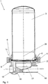
- a filter housing 1 essentially consists of a housing base 2, a housing dome 3, a clamp 4 and a seal 11.
- the housing base 2 has a Nutklemmstutzen 5 for GeHousedom 3 out.
- the Gerissausedom 3 has the housing base 2 through a collar clamp 6 with a circumferential collar 7, which engages in a circumferential groove 8 of the Nutklemmstutzens 5.
- the groove 8 is opened radially outward.
- the Nutklemmstutzen 5 has at its end face 9 a receiving groove / seal groove 10 for a seal 11, which is formed in the embodiment as an O-ring seal 12, on.
- the Nutklemmstutzen 5 and the collar clamping piece 6 are sealed by the seal 11 against each other and are pressed in a conventional manner by a clamp 13 against each other and fixed.
- the housing base 2 and the housing dome 3 are connected via an aseptic clamp connection 14, as is known from DIN 11864-3 or as a hygiene connection from DIN 11853-3.
- the housing base 2 has a lateral port 15 for fluid delivery, i. for the supply of liquid to be filtered, on.
- the port 15 merges into a vertically extending inflow channel 16 and leads to a filter, not shown, the liquid to be filtered.
- the housing base 2 has a central vertically extending outflow channel 17, which merges into a horizontal port 18 for fluid discharge.
- the housing base 2 has an annular base surface 19.
- the base surface 19 is delimited by its central circulating discharge opening 21.
- For receiving groove 10 of the seal 11 toward the base surface 19 is bounded by a circumferential inner surface 22 of an inner collar 23. Between the inner collar 23 and an inner collar 23 to the outside spaced outer collar 24, the receiving groove 10 is arranged for the O-ring seal 12.
- the base surface 19 is inclined relative to a transversely to the housing longitudinal axis 20 extending horizontal plane 25 by an angle 26 of 5 °, i. it falls to the housing longitudinal axis 20 down.
Landscapes
- Chemical & Material Sciences (AREA)
- Chemical Kinetics & Catalysis (AREA)
- Filtration Of Liquid (AREA)
- Separation Using Semi-Permeable Membranes (AREA)
- Pressure Vessels And Lids Thereof (AREA)
Description
- Die Erfindung betrifft ein Filtergehäuse für austauschbare Filter mit einer Gehäusebasis zur Aufnahme des Filters und einem den Filter überspannenden Gehäusedom, wobei die Gehäusebasis und der Gehäusedom über eine Aseptik-Klemmverbindung miteinander verbindbar sind, die gehäusebasisseitig einen Nutklemmstutzen und gehäusedomseitig einen Bundklemmstutzen aufweist, welche über eine Klammer in ihrer verbundenen Position gegeneinander fixiert sind, wobei der Nutklemmstutzen eine Dichtungsnut mit einer Dichtung aufweist, über die der Nutklemmstutzen gegenüber dem Bundklemmstutzen abdichtbar ist, wobei die Gehäusebasis einen Anschluss zur Zufuhr von zu filtrierender Flüssigkeit und einen Anschluss zur Abfuhr von filtrierter Flüssigkeit aufweist, und wobei die Gehäusebasis quer zur Gehäuselängsachse eine der Stirnfläche des eingesetzten Filters benachbarte Basisfläche aufweist.
- Aus dem Firmenprospekt "Products and Solutions for the Biopharmaceutical Industry" der Sartorius Stedim Biotech GmbH ist ein Filtergehäuse zur Filtration von Flüssigkeiten in der biopharmazeutischen Industrie bekannt.
Filtergehäuse für austauschbare Filter besteht aus einer Gehäusebasis zur Aufnahme des Filters und einem den Filter überspannenden Gehäusedom, wobei die Gehäusebasis und der Gehäusedom über eine Aseptik-Klemmverbindung miteinander verbunden werden. Die Gehäusebasis weist einen Nutklemmstutzen auf, der über eine Klammer mit einem Bundklemmstutzen des Gehäusedoms verbunden wird. Dabei weist der Nutklemmstutzen eine Dichtungsnut mit einer O-RingDichtung auf, über die der Nutklemmstutzen gegenüber dem Bundklemmstutzen abgedichtet ist. Die Gehäusebasis weist einen Anschluss zur Zufuhr von zu filtrierender Flüssigkeit und einen Anschluss zur Abfuhr von filtrierter Flüssigkeit auf, wobei die Gehäusebasis quer zur Gehäuselängsachse eine der Stirnfläche des eingesetzten Filters benachbarte Basisfläche aufweist, die eine zentrale Öffnung zu dem in den in den Anschluss zur Abfuhr der filtrierten Flüssigkeit mündenden Abflusskanal aufweist. - Nachteilig bei dem bekannten Filtergehäuse, das in seiner aseptischen Klemmverbindung der DIN 11864-3 und DIN 11853-3 entspricht und sich grundsätzlich bewährt hat, ist, dass beim Entleeren des Filtergehäuses Flüssigkeit auf der Basisfläche zur Stirnfläche des Filters hin zurückbleiben kann.
- Die
US 4,120,794 offenbart ein Filtergehäuse bei dem die Filterkerze über eine Feder zum Fixieren am Bodenflansch gehalten wird. Eine aseptische Verbindung wird nicht offenbart, d.h. das Medium welches im Gehäuse ansteht, fließt vom Innenraum zwischen die beiden Gehäuseteile aus Bodenflansch und Haubenklemmstutzen bis zum O-Ring. Der O-Ring befindet sich dabei in einer Standard-Rechteck-O-Ring-Nut. Nach dem Ablassen des Mediums aus dem Gehäuse bleibt der Teil des Mediums, der sich in dem Zwischenraum befindet, stehen und kann nicht abfließen. Darüber hinaus sammelt sich das Medium in der O-Ring-Nut. Beim Leerlaufen bleibt das Medium außerdem im Eingang stehen, da kein Entleerungsstutzen vorgesehen ist. - Aufgabe der vorliegenden Erfindung ist es daher, das bekannte Filtergehäuse so zu verbessern, dass sowohl beim Filtrieren als auch beim Reinigen bzw. Spülen, möglichst keine Flüssigkeitsreste zurückbleiben.
- Die Aufgabe wird in Verbindung mit dem Oberbegriff des Anspruches 1 dadurch gelöst, dass die Basisfläche nach innen zur Gehäuselängsachse hin gegenüber einer quer zur Gehäuselängsachse angeordneten horizontalen Ebene geneigt ist. Die Dichtungsnut ist zur Gehäuselängsachse hin von einem Innenkragen mit einer umlaufenden Innenfläche begrenzt, die die äußere Begrenzung für die Basisfläche bildet. Die Innenfläche verläuft dabei parallel zur Gehäuselängsachse, das heißt sie verläuft im Wesentlichen vertikal und trägt zu einem sicheren Flüssigkeitsabfluss bei.
- Durch die Neigung der Basisfläche zur Gehäuselängsachse bzw. zu ihrer zentralen Öffnung hin, können auch letzte Reste von Flüssigkeit auf der Basisfläche von selbst abfließen.
- Gemäß einer bevorzugten Ausführungsform der Erfindung ist die Basisfläche ringförmig mit einer zentralen Öffnung zu einem Flüssigkeitsabfluss hin ausgebildet.
- Grundsätzlich ist es möglich, die Basisfläche zur Dichtungsnut bzw. deren Begrenzung zu erhöhen oder die Basisfläche tiefer zu setzen und zur Gehäuselängsachse hin zu neigen bzw. abfallen zu lassen.
- Gemäß einer weiteren bevorzugten Ausführungsform der Erfindung ist die Basisfläche zur Gehäuselängsachse hin um einen Winkel geneigt ist, der größer ist als 2° und weiter bevorzugt größer ist als 4°. Als besonders günstig hat sich ein Winkel von 5° erwiesen.
- Nach einer weiteren bevorzugten Ausführungsform der Erfindung ist die Dichtung als eine O-Ringdichtung ausgebildet.
- Weitere Einzelheiten der Erfindung ergeben sich aus der nachfolgenden ausführlichen Beschreibung und den beigefügten Zeichnungen, in denen bevorzugte Ausführungsformen der Erfindung beispielhaft veranschaulicht sind.
- In den Zeichnungen zeigen:
- Figur 1:
- eine Seitenansicht eines Filtergehäuses im Schnitt;
- Figur 2:
- eine vergrößerte Darstellung der Einzelheit II aus
Figur 1 ; - Figur 3:
- eine räumliche Ansicht eines Filtergehäuses in verkleinerter Darstellung;
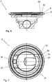
- Figur 4:
- eine Seitenansicht der Gehäusebasis von
Figur 1 im Schnitt; - Figur 5:
- eine vergrößerte Darstellung der Einzelheit V von
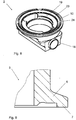
Figur 4 ; - Figur 6:
- eine Seitenansicht der Gehäusebasis von
Figur 4 entlang der Linie VI-VI geschnitten; - Figur 7:
- eine Draufsicht auf die Gehäusebasis von
Figur 4 ; - Figur 8:
- eine räumliche Darstellung der Gehäusebasis von
Figur 4 ; und - Figur 9:
- eine vergrößerte Darstellung des Gehäusedoms von
Figur 1 im Schnitt und Ausriss. - Ein Filtergehäuse 1 besteht im Wesentlichen aus einer Gehäusebasis 2, einem Gehäusedom 3, einer Klammer 4 und einer Dichtung 11.
- Die Gehäusebasis 2 weist zum Gehäusedom 3 hin einen Nutklemmstutzen 5 auf. Der Gehäusedom 3 weist zur Gehäusebasis 2 hin einen Bundklemmstutzen 6 mit einem umlaufenden Bund 7 auf, der in eine umlaufende Nut 8 des Nutklemmstutzens 5 eingreift. Die Nut 8 ist radial nach außen geöffnet. Der Nutklemmstutzen 5 weist an seiner Stirnfläche 9 eine Aufnahmenut/Dichtungsnut 10 für eine Dichtung 11, die im Ausführungsbeispiel als eine O-Ringdichtung 12 ausgebildet ist, auf.
- Der Nutklemmstutzen 5 und der Bundklemmstutzen 6 sind über die Dichtung 11 gegeneinander abdichtbar und werden in an sich bekannter Weise von einer Klammer 13 gegeneinander gepresst und fixiert. Damit sind die Gehäusebasis 2 und der Gehäusedom 3 über eine Aseptik-Klemmverbindung 14, wie sie aus der DIN 11864-3 oder als eine Hygieneverbindung aus der DIN 11853-3 bekannt ist, verbunden.
- Die Gehäusebasis 2 weist einen seitlichen Anschluss 15 zur Fluidzufuhr, d.h. zur Zufuhr von zu filtrierender Flüssigkeit, auf. Der Anschluss 15 geht in einen in vertikaler Richtung verlaufenden Zuflusskanal 16 über und führt einem nicht dargestellten Filter die zu filtrierende Flüssigkeit zu.
- Die Gehäusebasis 2 weist einen zentralen in vertikaler Richtung verlaufenden Abflusskanal 17 auf, der in einen horizontalen Anschluss 18 zur Fluidabfuhr übergeht. Zum Gehäusedom 3 hin weist die Gehäusebasis 2 eine ringförmige Basisfläche 19 auf. Zu der Gehäuselängsachse 20 hin wird die Basisfläche 19 von ihrer zentralen umlaufenden Abflussöffnung 21 begrenzt. Zur Aufnahmenut 10 der Dichtung 11 hin wird die Basisfläche 19 von einer umlaufenden Innenfläche 22 eines Innenkragens 23 begrenzt. Zwischen dem Innenkragen 23 und einem zum Innenkragen 23 nach außen hin beabstandeten Außenkragen 24 ist die Aufnahmenut 10 für die O-Ringdichtung 12 angeordnet.
- Die Basisfläche 19 ist gegenüber einer quer zur Gehäuselängsachse 20 verlaufenden horizontalen Ebene 25 um einen Winkel 26 von 5° geneigt, d.h. sie fällt zur Gehäuselängsachse 20 hin ab.
- Natürlich stellen die in der speziellen Beschreibung diskutierten und in den Figuren gezeigten Ausführungsformen nur illustrative Ausführungsbeispiele der vorliegenden Erfindung dar. Dem Fachmann ist im Lichte der hiesigen Offenbarung ein breites Spektrum an Variationsmöglichkeiten an die Hand gegeben.
-
- 1
- Filtergehäuse
- 2
- Gehäusebasis
- 3
- Gehäusedom
- 4
- Klammer
- 5
- Nutklemmstutzen
- 6
- Bundklemmstutzen
- 7
- Bund von 6
- 8
- Nut von 5
- 9
- Stirnfläche von 5
- 10
- Aufnahmenut/Dichtungsnut
- 11
- Dichtung
- 12
- O-Ringdichtung von 11
- 13
- Klammer
- 14
- Aseptik-Klemmverbindung
- 15
- Anschluss von 2
- 16
- Zuflusskanal
- 17
- Abflusskanal
- 18
- (horizontaler) Abschluss
- 19
- Basisfläche
- 20
- Gehäuselängsachse
- 21
- Abflussöffnung von 19
- 22
- umlaufende Innenfläche
- 23
- Innenkragen von 2
- 24
- Außenkragen von 2
- 25
- horizontale Ebene
- 26
- Winkel
Claims (6)
- Filtergehäuse (1) für austauschbare Filter mit einer Gehäusebasis (2) zur Aufnahme des Filters und einem den Filter überspannenden Gehäusedom (3), wobei die Gehäusebasis (2) und der Gehäusedom (3) über eine Aseptik-Klemmverbindung (14) miteinander verbindbar sind, die gehäusebasisseitig einen Nutklemmstutzen (5) und gehäusedomseitig einen Bundklemmstutzen (6) aufweist, welche über eine Klammer (4) in ihrer verbundenen Position gegeneinander fixiert sind, wobei der Nutklemmstutzen (5) eine Dichtungsnut (10) mit einer Dichtung (11) aufweist, über die der Nutklemmstutzen (5) gegenüber dem Bundklemmstutzen (6) abdichtbar ist, wobei die Gehäusebasis (2) einen Anschluss (15) zur Zufuhr von zu filtrierender Flüssigkeit und einen Anschluss (18) zur Abfuhr von filtrierter Flüssigkeit aufweist, und wobei die Gehäusebasis (2) quer zur Gehäuselängsachse (20) eine der Stirnfläche (9) des eingesetzten Filters benachbarte Basisfläche (19) aufweist,
dadurch gekennzeichnet,
dass die Basisfläche (19) nach innen zur Gehäuselängsachse (20) hin gegenüber einer quer zur Gehäuselängsachse (20) angeordneten horizontalen Ebene (25) geneigt ist und die Dichtungsnut (10) zur Gehäuselängsachse (20) hin von einem Innenkragen (23) mit einer umlaufenden Innenfläche (22) begrenzt ist, die die äußere Begrenzung (24) für die Basisfläche (19) bildet, wobei die umlaufende Innenfläche (22) im Wesentlichen vertikal und somit gemäß der Gehäuselängsachse (20) verläuft. - Filtergehäuse nach Anspruch 1,
dadurch gekennzeichnet,
dass die Basisfläche (19) ringförmig mit einer zentralen Öffnung (21) zu einem Flüssigkeitsabfluss (17) hin ausgebildet ist. - Filtergehäuse nach einem der Ansprüche 1 und 2,
dadurch gekennzeichnet,
dass die Basisfläche (19) zur Gehäuselängsachse (20) hin um einen Winkel (26) geneigt ist, der größer als 2° ist. - Filtergehäuse nach Anspruch 3,
dadurch gekennzeichnet,
dass die Basisfläche (19) zur Gehäuselängsachse (20) hin um einen Winkel (26) von größer als 4° geneigt ist. - Filtergehäuse nach Anspruch 4,
dadurch gekennzeichnet,
dass die Basisfläche (19) zur Gehäuselängsachse (20) hin um einen Winkel (26) von 5° geneigt ist. - Filtergehäuse nach einem der Ansprüche 1 bis 5,
dadurch gekennzeichnet,
dass die Dichtung (11) als eine O-Ringdichtung (12) ausgebildet ist.
Applications Claiming Priority (2)
| Application Number | Priority Date | Filing Date | Title |
|---|---|---|---|
| DE202012003252U DE202012003252U1 (de) | 2012-03-30 | 2012-03-30 | Filtergehäuse für austauschbare Filter |
| PCT/EP2013/000683 WO2013143651A1 (de) | 2012-03-30 | 2013-03-07 | Filtergehäuse für austauschbare filter |
Publications (2)
| Publication Number | Publication Date |
|---|---|
| EP2830733A1 EP2830733A1 (de) | 2015-02-04 |
| EP2830733B1 true EP2830733B1 (de) | 2018-02-21 |
Family
ID=46145091
Family Applications (1)
| Application Number | Title | Priority Date | Filing Date |
|---|---|---|---|
| EP13709329.0A Active EP2830733B1 (de) | 2012-03-30 | 2013-03-07 | Filtergehäuse für austauschbare filter |
Country Status (5)
| Country | Link |
|---|---|
| US (1) | US9636612B2 (de) |
| EP (1) | EP2830733B1 (de) |
| CN (1) | CN104203365B (de) |
| DE (1) | DE202012003252U1 (de) |
| WO (1) | WO2013143651A1 (de) |
Families Citing this family (3)
| Publication number | Priority date | Publication date | Assignee | Title |
|---|---|---|---|---|
| GB2544055B (en) * | 2015-11-03 | 2020-05-20 | Mann & Hummel Gmbh | Centrifugal seperator with drainage slots |
| CN105253994A (zh) * | 2015-11-20 | 2016-01-20 | 无锡山川环保机械有限公司 | 流化床横梁支架 |
| TR201902651A2 (tr) * | 2019-02-21 | 2020-09-21 | Serdar Plastik Sanayi Ve Ticaret Anonim Sirketi | 2K Sızdırmaz Püskürtmeli Döner Pervane |
Family Cites Families (15)
| Publication number | Priority date | Publication date | Assignee | Title |
|---|---|---|---|---|
| AT26543B (de) | 1904-07-08 | 1906-11-26 | F W Schilbach Fa | Sägemaschine zum selbsttätigen gleichzeitigen Abtrennen einzelner Stücke von mehreren Werkstücken. |
| US4120794A (en) * | 1977-03-31 | 1978-10-17 | Amf Incorporated | Filter cartridge assembly |
| US4525725A (en) | 1982-12-13 | 1985-06-25 | Iwatsu Electric Co., Ltd. | Method and apparatus for forming magnetic latent images |
| DE3617420C2 (de) | 1986-05-23 | 1994-09-22 | Bosch Gmbh Robert | Filter zum Reinigen von Flüssigkeiten |
| US5209845A (en) * | 1991-06-11 | 1993-05-11 | Charles Sims | Seal for injection molded filter body |
| JPH08276107A (ja) | 1995-04-04 | 1996-10-22 | Kanebo Ltd | 使い捨て型濾過装置 |
| DE19828840C1 (de) | 1998-06-27 | 1999-10-28 | Sartorius Gmbh | Mehrfachfiltergehäuse mit Verriegelungseinrichtung für Filterelemente |
| US6602412B2 (en) * | 2001-03-01 | 2003-08-05 | Inflos Designs | Single cartridge filter housing |
| US6977040B2 (en) * | 2001-03-19 | 2005-12-20 | Allegheny Bradford Corporation | Integrated filter housing with associated cleaning system and method |
| US6902598B2 (en) | 2003-05-02 | 2005-06-07 | Fleetguard, Inc. | Filter with efficiently sealed end |
| US7704392B2 (en) * | 2008-01-18 | 2010-04-27 | Mks Instruments, Inc. | Minimal residual liquid retention filter housing |
| DE102008027250B4 (de) * | 2008-06-06 | 2010-07-15 | Sartorius Stedim Biotech Gmbh | Gehäuse zur Filtration |
| EP2349524B1 (de) * | 2008-09-24 | 2014-11-12 | Repligen Corporation | Siebfiltermodul für die wechselstromfiltration |
| CN201711037U (zh) * | 2010-06-30 | 2011-01-19 | 浙江雅乐思电器科技股份有限公司 | 一种过滤器 |
| CN202044845U (zh) * | 2011-05-06 | 2011-11-23 | 王锦林 | 净水机的过滤筒 |
-
2012
- 2012-03-30 DE DE202012003252U patent/DE202012003252U1/de not_active Expired - Lifetime
-
2013
- 2013-03-07 EP EP13709329.0A patent/EP2830733B1/de active Active
- 2013-03-07 WO PCT/EP2013/000683 patent/WO2013143651A1/de not_active Ceased
- 2013-03-07 US US14/389,440 patent/US9636612B2/en active Active
- 2013-03-07 CN CN201380017394.5A patent/CN104203365B/zh active Active
Also Published As
| Publication number | Publication date |
|---|---|
| WO2013143651A1 (de) | 2013-10-03 |
| DE202012003252U1 (de) | 2012-04-25 |
| CN104203365A (zh) | 2014-12-10 |
| EP2830733A1 (de) | 2015-02-04 |
| US20150060343A1 (en) | 2015-03-05 |
| US9636612B2 (en) | 2017-05-02 |
| CN104203365B (zh) | 2016-05-11 |
Similar Documents
| Publication | Publication Date | Title |
|---|---|---|
| EP3271043B1 (de) | Filtervorrichtung | |
| WO2011047754A1 (de) | Filtervorrichtung sowie filterelement für den einsatz bei einer solchen filtervorrichtung | |
| DE112016002154T5 (de) | Pneumatischer Filter und Filterelement | |
| DE102009013070A1 (de) | Filtervorrichtung, insbesondere Rücklauf-Saugfilter, sowie Filterelement für den Einsatz bei einer solchen Filtervorrichtung | |
| WO2016169838A1 (de) | Sekundärelement für ein filtersystem sowie filtersystem mit einem sekundärelement | |
| EP3621717A1 (de) | Filtervorrichtung | |
| DE102016011950A1 (de) | Filterelement, insbesondere zur Gasfiltration | |
| DE102013012917A1 (de) | Flüssigkeitsfilter, insbesondere für Kraftstoff | |
| WO2013143651A1 (de) | Filtergehäuse für austauschbare filter | |
| EP2910290B1 (de) | Flüssigkeitsfilter | |
| DE19857751A1 (de) | Modulfilter mit zumindest einem Zulauf für Unfiltrat und einem Ablauf für das Filtrat und mit zumindest einem Filtermodul | |
| WO2017084657A1 (de) | Filterscheibe | |
| AT396874B (de) | Spaltfilter, vorzugsweise für hochviskose flüssigkeiten | |
| EP3403708A1 (de) | Filtersystem mit zentralelement und siebfilter | |
| DE102012022189B3 (de) | Filteranordnung zur Filtration von in einer Flüssigkeit feinstverteilt vorliegenden festen Stoffen | |
| EP3328701A1 (de) | Kupplungssystem, insbesondere kupplungssystem zur pneumatischen verbindung einer pneumatischen bremsanlage eines zugfahrzeuges und eines anhängers | |
| WO2003064106A1 (de) | Vorrichtung zum separieren und austragen von spänen und arbeitsflüssigkeit | |
| DE102012007627B4 (de) | Filterelement | |
| EP1419807B1 (de) | Filtereinrichtung mit einem auswechselbaren Filterelement | |
| DE10240666B4 (de) | Flüssigkeitsfilter, insbesondere für Getriebeöl in Kraftfahrzeugen | |
| DE4424232C2 (de) | Rückspülbare Filtereinrichtung | |
| EP0650753A2 (de) | Rückspülbare Filtereinrichtung | |
| DE102021005289A1 (de) | Filtervorrichtung | |
| EP3592447B1 (de) | Filterelement für eine werkzeugmaschine, werkzeugmaschine, verwendung und austauschverfahren | |
| DE112008002390B4 (de) | Wechselfilter |
Legal Events
| Date | Code | Title | Description |
|---|---|---|---|
| PUAI | Public reference made under article 153(3) epc to a published international application that has entered the european phase |
Free format text: ORIGINAL CODE: 0009012 |
|
| 17P | Request for examination filed |
Effective date: 20141030 |
|
| AK | Designated contracting states |
Kind code of ref document: A1 Designated state(s): AL AT BE BG CH CY CZ DE DK EE ES FI FR GB GR HR HU IE IS IT LI LT LU LV MC MK MT NL NO PL PT RO RS SE SI SK SM TR |
|
| AX | Request for extension of the european patent |
Extension state: BA ME |
|
| DAX | Request for extension of the european patent (deleted) | ||
| 17Q | First examination report despatched |
Effective date: 20160623 |
|
| GRAP | Despatch of communication of intention to grant a patent |
Free format text: ORIGINAL CODE: EPIDOSNIGR1 |
|
| INTG | Intention to grant announced |
Effective date: 20171005 |
|
| GRAS | Grant fee paid |
Free format text: ORIGINAL CODE: EPIDOSNIGR3 |
|
| GRAA | (expected) grant |
Free format text: ORIGINAL CODE: 0009210 |
|
| AK | Designated contracting states |
Kind code of ref document: B1 Designated state(s): AL AT BE BG CH CY CZ DE DK EE ES FI FR GB GR HR HU IE IS IT LI LT LU LV MC MK MT NL NO PL PT RO RS SE SI SK SM TR |
|
| REG | Reference to a national code |
Ref country code: GB Ref legal event code: FG4D Free format text: NOT ENGLISH |
|
| REG | Reference to a national code |
Ref country code: CH Ref legal event code: EP |
|
| REG | Reference to a national code |
Ref country code: AT Ref legal event code: REF Ref document number: 971096 Country of ref document: AT Kind code of ref document: T Effective date: 20180315 Ref country code: FR Ref legal event code: PLFP Year of fee payment: 6 |
|
| REG | Reference to a national code |
Ref country code: IE Ref legal event code: FG4D Free format text: LANGUAGE OF EP DOCUMENT: GERMAN |
|
| REG | Reference to a national code |
Ref country code: DE Ref legal event code: R096 Ref document number: 502013009455 Country of ref document: DE |
|
| REG | Reference to a national code |
Ref country code: NL Ref legal event code: MP Effective date: 20180221 |
|
| REG | Reference to a national code |
Ref country code: LT Ref legal event code: MG4D |
|
| PG25 | Lapsed in a contracting state [announced via postgrant information from national office to epo] |
Ref country code: FI Free format text: LAPSE BECAUSE OF FAILURE TO SUBMIT A TRANSLATION OF THE DESCRIPTION OR TO PAY THE FEE WITHIN THE PRESCRIBED TIME-LIMIT Effective date: 20180221 Ref country code: CY Free format text: LAPSE BECAUSE OF FAILURE TO SUBMIT A TRANSLATION OF THE DESCRIPTION OR TO PAY THE FEE WITHIN THE PRESCRIBED TIME-LIMIT Effective date: 20180221 Ref country code: NO Free format text: LAPSE BECAUSE OF FAILURE TO SUBMIT A TRANSLATION OF THE DESCRIPTION OR TO PAY THE FEE WITHIN THE PRESCRIBED TIME-LIMIT Effective date: 20180521 Ref country code: NL Free format text: LAPSE BECAUSE OF FAILURE TO SUBMIT A TRANSLATION OF THE DESCRIPTION OR TO PAY THE FEE WITHIN THE PRESCRIBED TIME-LIMIT Effective date: 20180221 Ref country code: HR Free format text: LAPSE BECAUSE OF FAILURE TO SUBMIT A TRANSLATION OF THE DESCRIPTION OR TO PAY THE FEE WITHIN THE PRESCRIBED TIME-LIMIT Effective date: 20180221 Ref country code: LT Free format text: LAPSE BECAUSE OF FAILURE TO SUBMIT A TRANSLATION OF THE DESCRIPTION OR TO PAY THE FEE WITHIN THE PRESCRIBED TIME-LIMIT Effective date: 20180221 Ref country code: ES Free format text: LAPSE BECAUSE OF FAILURE TO SUBMIT A TRANSLATION OF THE DESCRIPTION OR TO PAY THE FEE WITHIN THE PRESCRIBED TIME-LIMIT Effective date: 20180221 |
|
| PG25 | Lapsed in a contracting state [announced via postgrant information from national office to epo] |
Ref country code: LV Free format text: LAPSE BECAUSE OF FAILURE TO SUBMIT A TRANSLATION OF THE DESCRIPTION OR TO PAY THE FEE WITHIN THE PRESCRIBED TIME-LIMIT Effective date: 20180221 Ref country code: SE Free format text: LAPSE BECAUSE OF FAILURE TO SUBMIT A TRANSLATION OF THE DESCRIPTION OR TO PAY THE FEE WITHIN THE PRESCRIBED TIME-LIMIT Effective date: 20180221 Ref country code: GR Free format text: LAPSE BECAUSE OF FAILURE TO SUBMIT A TRANSLATION OF THE DESCRIPTION OR TO PAY THE FEE WITHIN THE PRESCRIBED TIME-LIMIT Effective date: 20180522 Ref country code: RS Free format text: LAPSE BECAUSE OF FAILURE TO SUBMIT A TRANSLATION OF THE DESCRIPTION OR TO PAY THE FEE WITHIN THE PRESCRIBED TIME-LIMIT Effective date: 20180221 Ref country code: BG Free format text: LAPSE BECAUSE OF FAILURE TO SUBMIT A TRANSLATION OF THE DESCRIPTION OR TO PAY THE FEE WITHIN THE PRESCRIBED TIME-LIMIT Effective date: 20180521 |
|
| PG25 | Lapsed in a contracting state [announced via postgrant information from national office to epo] |
Ref country code: MT Free format text: LAPSE BECAUSE OF FAILURE TO SUBMIT A TRANSLATION OF THE DESCRIPTION OR TO PAY THE FEE WITHIN THE PRESCRIBED TIME-LIMIT Effective date: 20180221 |
|
| PG25 | Lapsed in a contracting state [announced via postgrant information from national office to epo] |
Ref country code: PL Free format text: LAPSE BECAUSE OF FAILURE TO SUBMIT A TRANSLATION OF THE DESCRIPTION OR TO PAY THE FEE WITHIN THE PRESCRIBED TIME-LIMIT Effective date: 20180221 Ref country code: AL Free format text: LAPSE BECAUSE OF FAILURE TO SUBMIT A TRANSLATION OF THE DESCRIPTION OR TO PAY THE FEE WITHIN THE PRESCRIBED TIME-LIMIT Effective date: 20180221 Ref country code: IT Free format text: LAPSE BECAUSE OF FAILURE TO SUBMIT A TRANSLATION OF THE DESCRIPTION OR TO PAY THE FEE WITHIN THE PRESCRIBED TIME-LIMIT Effective date: 20180221 Ref country code: EE Free format text: LAPSE BECAUSE OF FAILURE TO SUBMIT A TRANSLATION OF THE DESCRIPTION OR TO PAY THE FEE WITHIN THE PRESCRIBED TIME-LIMIT Effective date: 20180221 Ref country code: RO Free format text: LAPSE BECAUSE OF FAILURE TO SUBMIT A TRANSLATION OF THE DESCRIPTION OR TO PAY THE FEE WITHIN THE PRESCRIBED TIME-LIMIT Effective date: 20180221 |
|
| REG | Reference to a national code |
Ref country code: CH Ref legal event code: PL |
|
| REG | Reference to a national code |
Ref country code: DE Ref legal event code: R097 Ref document number: 502013009455 Country of ref document: DE |
|
| PG25 | Lapsed in a contracting state [announced via postgrant information from national office to epo] |
Ref country code: CZ Free format text: LAPSE BECAUSE OF FAILURE TO SUBMIT A TRANSLATION OF THE DESCRIPTION OR TO PAY THE FEE WITHIN THE PRESCRIBED TIME-LIMIT Effective date: 20180221 Ref country code: DK Free format text: LAPSE BECAUSE OF FAILURE TO SUBMIT A TRANSLATION OF THE DESCRIPTION OR TO PAY THE FEE WITHIN THE PRESCRIBED TIME-LIMIT Effective date: 20180221 Ref country code: SM Free format text: LAPSE BECAUSE OF FAILURE TO SUBMIT A TRANSLATION OF THE DESCRIPTION OR TO PAY THE FEE WITHIN THE PRESCRIBED TIME-LIMIT Effective date: 20180221 Ref country code: MC Free format text: LAPSE BECAUSE OF FAILURE TO SUBMIT A TRANSLATION OF THE DESCRIPTION OR TO PAY THE FEE WITHIN THE PRESCRIBED TIME-LIMIT Effective date: 20180221 Ref country code: SK Free format text: LAPSE BECAUSE OF FAILURE TO SUBMIT A TRANSLATION OF THE DESCRIPTION OR TO PAY THE FEE WITHIN THE PRESCRIBED TIME-LIMIT Effective date: 20180221 |
|
| REG | Reference to a national code |
Ref country code: BE Ref legal event code: MM Effective date: 20180331 |
|
| REG | Reference to a national code |
Ref country code: IE Ref legal event code: MM4A |
|
| PLBE | No opposition filed within time limit |
Free format text: ORIGINAL CODE: 0009261 |
|
| STAA | Information on the status of an ep patent application or granted ep patent |
Free format text: STATUS: NO OPPOSITION FILED WITHIN TIME LIMIT |
|
| PG25 | Lapsed in a contracting state [announced via postgrant information from national office to epo] |
Ref country code: LU Free format text: LAPSE BECAUSE OF NON-PAYMENT OF DUE FEES Effective date: 20180307 |
|
| 26N | No opposition filed |
Effective date: 20181122 |
|
| PG25 | Lapsed in a contracting state [announced via postgrant information from national office to epo] |
Ref country code: IE Free format text: LAPSE BECAUSE OF NON-PAYMENT OF DUE FEES Effective date: 20180307 |
|
| PG25 | Lapsed in a contracting state [announced via postgrant information from national office to epo] |
Ref country code: LI Free format text: LAPSE BECAUSE OF NON-PAYMENT OF DUE FEES Effective date: 20180331 Ref country code: BE Free format text: LAPSE BECAUSE OF NON-PAYMENT OF DUE FEES Effective date: 20180331 Ref country code: CH Free format text: LAPSE BECAUSE OF NON-PAYMENT OF DUE FEES Effective date: 20180331 Ref country code: SI Free format text: LAPSE BECAUSE OF FAILURE TO SUBMIT A TRANSLATION OF THE DESCRIPTION OR TO PAY THE FEE WITHIN THE PRESCRIBED TIME-LIMIT Effective date: 20180221 |
|
| REG | Reference to a national code |
Ref country code: AT Ref legal event code: MM01 Ref document number: 971096 Country of ref document: AT Kind code of ref document: T Effective date: 20180307 |
|
| PG25 | Lapsed in a contracting state [announced via postgrant information from national office to epo] |
Ref country code: AT Free format text: LAPSE BECAUSE OF NON-PAYMENT OF DUE FEES Effective date: 20180307 |
|
| PG25 | Lapsed in a contracting state [announced via postgrant information from national office to epo] |
Ref country code: TR Free format text: LAPSE BECAUSE OF FAILURE TO SUBMIT A TRANSLATION OF THE DESCRIPTION OR TO PAY THE FEE WITHIN THE PRESCRIBED TIME-LIMIT Effective date: 20180221 |
|
| PG25 | Lapsed in a contracting state [announced via postgrant information from national office to epo] |
Ref country code: PT Free format text: LAPSE BECAUSE OF FAILURE TO SUBMIT A TRANSLATION OF THE DESCRIPTION OR TO PAY THE FEE WITHIN THE PRESCRIBED TIME-LIMIT Effective date: 20180221 Ref country code: HU Free format text: LAPSE BECAUSE OF FAILURE TO SUBMIT A TRANSLATION OF THE DESCRIPTION OR TO PAY THE FEE WITHIN THE PRESCRIBED TIME-LIMIT; INVALID AB INITIO Effective date: 20130307 |
|
| PG25 | Lapsed in a contracting state [announced via postgrant information from national office to epo] |
Ref country code: MK Free format text: LAPSE BECAUSE OF NON-PAYMENT OF DUE FEES Effective date: 20180221 |
|
| PG25 | Lapsed in a contracting state [announced via postgrant information from national office to epo] |
Ref country code: IS Free format text: LAPSE BECAUSE OF FAILURE TO SUBMIT A TRANSLATION OF THE DESCRIPTION OR TO PAY THE FEE WITHIN THE PRESCRIBED TIME-LIMIT Effective date: 20180621 |
|
| P01 | Opt-out of the competence of the unified patent court (upc) registered |
Effective date: 20230526 |
|
| PGFP | Annual fee paid to national office [announced via postgrant information from national office to epo] |
Ref country code: GB Payment date: 20260324 Year of fee payment: 14 |
|
| PGFP | Annual fee paid to national office [announced via postgrant information from national office to epo] |
Ref country code: DE Payment date: 20260320 Year of fee payment: 14 |
|
| PGFP | Annual fee paid to national office [announced via postgrant information from national office to epo] |
Ref country code: FR Payment date: 20260325 Year of fee payment: 14 |