EP2830338A1 - Subscriber server, monitoring server, mobile terminal, method related thereto, and computer-readable medium - Google Patents
Subscriber server, monitoring server, mobile terminal, method related thereto, and computer-readable medium Download PDFInfo
- Publication number
- EP2830338A1 EP2830338A1 EP13763835.9A EP13763835A EP2830338A1 EP 2830338 A1 EP2830338 A1 EP 2830338A1 EP 13763835 A EP13763835 A EP 13763835A EP 2830338 A1 EP2830338 A1 EP 2830338A1
- Authority
- EP
- European Patent Office
- Prior art keywords
- mobile terminal
- subscriber
- server
- data
- behavior data
- Prior art date
- Legal status (The legal status is an assumption and is not a legal conclusion. Google has not performed a legal analysis and makes no representation as to the accuracy of the status listed.)
- Withdrawn
Links
Images



Classifications
-
- H—ELECTRICITY
- H04—ELECTRIC COMMUNICATION TECHNIQUE
- H04W—WIRELESS COMMUNICATION NETWORKS
- H04W8/00—Network data management
- H04W8/18—Processing of user or subscriber data, e.g. subscribed services, user preferences or user profiles; Transfer of user or subscriber data
- H04W8/20—Transfer of user or subscriber data
-
- H—ELECTRICITY
- H04—ELECTRIC COMMUNICATION TECHNIQUE
- H04W—WIRELESS COMMUNICATION NETWORKS
- H04W76/00—Connection management
- H04W76/20—Manipulation of established connections
- H04W76/27—Transitions between radio resource control [RRC] states
-
- H—ELECTRICITY
- H04—ELECTRIC COMMUNICATION TECHNIQUE
- H04W—WIRELESS COMMUNICATION NETWORKS
- H04W8/00—Network data management
- H04W8/02—Processing of mobility data, e.g. registration information at HLR [Home Location Register] or VLR [Visitor Location Register]; Transfer of mobility data, e.g. between HLR, VLR or external networks
- H04W8/04—Registration at HLR or HSS [Home Subscriber Server]
-
- H—ELECTRICITY
- H04—ELECTRIC COMMUNICATION TECHNIQUE
- H04W—WIRELESS COMMUNICATION NETWORKS
- H04W88/00—Devices specially adapted for wireless communication networks, e.g. terminals, base stations or access point devices
- H04W88/08—Access point devices
Definitions
- a third aspect includes a mobile terminal being connected to a mobile core network through a radio access network.
- the mobile terminal includes a transmission unit that transmits behavior data of the mobile terminal to a monitoring server.
- the behavior data is used to update subscriber data regarding the mobile terminal managed by a subscriber server arranged in the mobile core network.
- a fifth aspect includes a method performed by a monitoring server.
- the method includes the following (a) and (b):
- a seventh aspect includes a program for causing a computer to execute the method according to the fourth aspect stated above.
- An eighth aspect includes a program for causing a computer to execute the method according to the fifth aspect stated above.
- the mobile terminal 200 transmits behavior data of the mobile terminal 200 to the UE monitoring server 700.
- the behavior data is used to update the subscriber data 410 regarding the mobile terminal 200 based on the communication between the UE monitoring server 700 and the subscriber server 400.
- Fig. 2 is a sequence diagram showing one example of the communication to update the subscriber data 410 according to this embodiment.
- the mobile terminal 200 collects the behavior data of the mobile terminal 200.
- the mobile terminal 200 transmits the behavior data to the UE monitoring server 700.
- the UE monitoring server 700 communicates with the subscriber server 400 to update the subscriber data 410 regarding the mobile terminal 200 based on the behavior data.
- the UE monitoring server 700 transmits to the subscriber server 400 an update request of the subscriber data 410.
- the update request includes configuration data of the UE inactivity timer 101 (i.e., expiration period of the timer).
- the subscriber data 410 managed by the subscriber server 400 can be updated from outside of the mobile core network 20 based on the behavior data of the mobile terminal 200.
- the UE monitoring server 700 may be a server having an Access Network Discovery and Selection Function (ANDSF).
- the ANDSF communicates with the mobile terminal 200 on an application layer using an S14 interface.
- the ANDSF provides to the mobile terminal 200 information (e.g., Inter-system mobility policy, Access network discovery information, Inter-System Routing Policy) that is necessary to search and select a non-3GPP access network (e.g., wireless LAN, WiMAX).
- a non-3GPP access network e.g., wireless LAN, WiMAX.
- the mobile terminal 200 transmits the behavior data to the UE monitoring server 700 through the S14 interface.
- the detail of the ANDSF is described in the section 4.8 of 3GPP TS 23.402 V11.2.0 (2012-03).
Landscapes
- Engineering & Computer Science (AREA)
- Computer Networks & Wireless Communication (AREA)
- Signal Processing (AREA)
- Databases & Information Systems (AREA)
- Mobile Radio Communication Systems (AREA)
Abstract
Description
- The present invention relates to a mobile communication system, and more particularly, to update of subscriber data held in a subscriber server.
-
Patent literature 1 discloses measuring, by a mobile terminal or a network (i.e., a base station or a gateway), duration time of an inactive state during which the mobile terminal does not perform communication, and causing the mobile terminal to transition to a sleep mode when the duration time exceeds a predetermined expiration period.Patent literature 1 further discloses measuring, by a mobile terminal or a network (i.e., a base station or a gateway), a communication frequency of the mobile terminal, and changing the timer expiration period regarding the sleep mode transition based on the communication frequency of the mobile terminal.Patent literature 1 further discloses changing the timer expiration period regarding the sleep mode transition based on remaining battery power of the mobile terminal. - Further, Non-patent
literature - The following are definitions of the terms "CONNECTED state" and "IDLE state" used in this specification and Claims. The "IDLE state" means a state in which a mobile terminal does not continuously transmit or receive control signals for session management and mobility management to or from a mobile core network, and radio resources in a radio access network have been released. The radio access network is, for example, UTRAN or E-UTRAN. The mobile core network is, for example, a General Packet Radio Service (GPRS) packet core or an Evolved Packet Core (EPC). One example of the IDLE state is an EPS Connection Management IDLE (ECM-IDLE) state and a Radio Resource Control IDLE (RRC_IDLE) state of the 3GPP. In the RRC_IDLE, radio resources in the Evolved Universal Terrestrial Radio Access Network (E-UTRAN) have been released.
- Meanwhile, the "CONNECTED state" means a state in which, as in an ECM-CONNECTED state and an RRC_CONNECTED state of the 3GPP stated above, radio resources at least for transmitting and receiving control signals (control messages) for session management and mobility management between the mobile terminal and the mobile core network are secured in a radio access network, and such a connection is established as to be able to transmit and receive control signals (control messages) between the mobile terminal and the mobile core network. In short, the "CONNECTED state" is a state in which the mobile terminal is connected to the mobile core network so as to be able to at least transmit and receive the control signals (control messages) for the session management and the mobility management. In other words, the "CONNECTED state" does not require a state in which a data bearer is configured for transmitting and receiving user data between the mobile terminal and an external packet data network (PDN). The "CONNECTED state" can also be called an "ACTIVE state".
- Typically, the mobile core network manages the location of a mobile terminal which is in the CONNECTED state on a cell by cell basis, and manages the location of a mobile terminal which is in the IDLE state in units of location registration areas (e.g., tracking areas, routing areas) including a plurality of cells. When moved from one location registration area to another location registration area, the mobile terminal which is in the IDLE state transmits a message indicating an update of the location registration area to the mobile core network. The mobile core network transmits, upon arrival of downlink traffic (downlink data or incoming voice call) to the mobile terminal which is in the IDLE state, a paging signal into a paging area defined based on the location registration area.
- [Patent Literature 1] Japanese Unexamined Patent Application Publication No.
H11-313370 -
- [Non-Patent Literature 1] 3GPP S2-120475, "Inactivity timer management function", NTT docomo and NEC, 3GPP TSG-SA2 Meeting #89, Vancouver, Canada, 6-10 February 2012
- [Non-Patent Literature 2] 3GPP S2-120476, "Inactivity timer management function", NTT docomo and NEC, 3GPP TSG-SA2 Meeting #89, Vancouver, Canada, 6-10 February 2012
- There are various types and various applications of mobile terminals connected to a mobile core network through a radio access network. The types of the mobile terminals include, for example, smartphones, tablets, and Machine Type Communication (MTC) devices. It is supposed that smartphones generally have different traffic characteristics depending on the applications that are installed. Further, the MTC devices are mounted on various devices including vending machines, gas meters, electric meters, vehicles, railway vehicles, environmental sensors, traffic sensors and the like. It is therefore supposed that the MTC devices have different traffic characteristics depending on its applications.
- The inventors have studied about changing a configuration of radio control parameters based on the behavior of a mobile terminal such as traffic characteristics of the mobile terminal. The control of the UE inactivity timer, which is one of the radio control parameters, is described here. It is desirable that the behavior data of the mobile terminal can be collected by a monitoring server arranged outside the radio access network and the mobile core network. The monitoring server may be operated not only by a mobile network operator but also by an external service operator. As already described above, however, the configuration data of the UE inactivity timer may be managed by the HSS as the subscriber data. It is currently impossible to change the subscriber data managed by the HSS from an outside of the mobile core network.
- Note that the subscriber data managed by the HSS is not limited to the UE inactivity timer stated above. The subscriber data includes, for example, a QoS Class (QCI) of a data bearer, an Access Point Name (APN), or an IP address of a mobile terminal. If the subscriber data can be changed based on the behavior of the mobile terminal collected by the monitoring server, operations of a mobile network adapted for the mobile terminal can be provided. It is currently impossible, however, to change these subscriber data from an outside of the mobile core network.
- The present invention has been made based on the above study by the inventors, and aims to provide a subscriber server, monitoring server, mobile terminal, methods of controlling them, and program for allowing update of subscriber data managed by a subscriber server (e.g., HSS) from an outside of the mobile core network.
- A first aspect includes a subscriber server being arranged in a mobile core network and managing subscriber data regarding a mobile terminal connected to the mobile core network through a radio access network. The subscriber server includes first and second communication units and an update unit. The first communication unit performs communication with a first server to update the subscriber data based on behavior data of the mobile terminal. The update unit updates the subscriber data based on the communication with the first server. The second communication unit transmits the subscriber data to a network node arranged in the mobile core network.
- A second aspect includes a monitoring server. The monitoring server includes an acquiring unit and a communication unit. The acquiring unit acquires behavior data of a mobile terminal capable of being connected to a mobile core network through a radio access network. The communication unit performs communication with a subscriber server arranged in the mobile core network to update subscriber data regarding the mobile terminal based on the behavior data.
- A third aspect includes a mobile terminal being connected to a mobile core network through a radio access network. The mobile terminal includes a transmission unit that transmits behavior data of the mobile terminal to a monitoring server. The behavior data is used to update subscriber data regarding the mobile terminal managed by a subscriber server arranged in the mobile core network.
- A fourth aspect includes a method performed by a subscriber server. The subscriber server is arranged in a mobile core network and manages subscriber data regarding a mobile terminal connected to the mobile core network through a radio access network. The method according to this aspect includes the following (a) to (c):
- (a) performing communication with a first server to update the subscriber data based on behavior data of the mobile terminal;
- (b) updating the subscriber data based on the communication with the first server; and
- (c) transmitting the subscriber data to a network node arranged in the mobile core network.
- A fifth aspect includes a method performed by a monitoring server. The method includes the following (a) and (b):
- (a) acquiring behavior data of a mobile terminal capable of being connected to a mobile core network through a radio access network; and
- (b) performing communication with a subscriber server arranged in the mobile core network to update subscriber data regarding the mobile terminal based on the behavior data.
- A sixth aspect includes a method performed by a mobile terminal being connected to a mobile core network through a radio access network. The method includes transmitting behavior data of the mobile terminal to a monitoring server. The behavior data is used to update subscriber data regarding the mobile terminal managed by a subscriber server arranged in the mobile core network.
- A seventh aspect includes a program for causing a computer to execute the method according to the fourth aspect stated above.
- An eighth aspect includes a program for causing a computer to execute the method according to the fifth aspect stated above.
- A ninth aspect includes a program for causing a computer to execute the method according to the sixth aspect stated above.
- According to aspects of the present invention stated above, it is possible to provide a subscriber server, monitoring server, mobile terminal, methods of controlling them, and program for allowing update of subscriber data managed by a subscriber server (e.g., HSS) from an outside of the mobile core network.
-
-
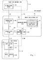
Fig. 1 is a block diagram showing a configuration example of a mobile communication system according to an embodiment of the present invention; -
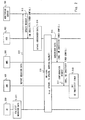
Fig. 2 is a sequence diagram showing an operation of a mobile communication system according to an embodiment of the present invention; -
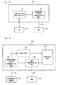
Fig. 3 is a block diagram showing a configuration example of a mobile terminal according to an embodiment of the present invention; -
Fig. 4 is a block diagram showing another configuration example of a mobile terminal according to an embodiment of the present invention; -
Fig. 5 is a block diagram showing a configuration example of a monitoring server according to an embodiment of the present invention; -
Fig. 6 is a block diagram showing a configuration example of a subscriber server according to an embodiment of the present invention; -
Fig. 7 is a block diagram showing a configuration example of a mobile communication system according to an embodiment of the present invention; -
Fig. 8 is a block diagram showing a configuration example of a mobile communication system according to an embodiment of the present invention; and -
Fig. 9 is a block diagram showing a configuration example of a mobile communication system according to an embodiment of the present invention. - Hereinafter, with reference to the drawings, specific embodiments to which the present invention is applied will be described in detail. Throughout the drawings, the identical and corresponding components are denoted by the same reference symbols, and overlapping description will be omitted as appropriate for the sake of clarification of description.
-
Fig. 1 is a block diagram showing a configuration example of a network including amobile terminal 200, asubscriber server 400, and aUE monitoring server 700 according to this embodiment. The configuration example shown inFig. 1 includes a radio access network (RAN) 10, amobile core network 20, and a packet data network (PDN) 30. The basic configurations and functions of theRAN 10, themobile core network 20, and the PDN 30 will be described first. - The
RAN 10 includes abase station 100 and themobile terminal 200. Thebase station 100 is connected to themobile terminal 200 by means of a radio access technology. Themobile terminal 200 has a radio interface, is connected to thebase station 100 by means of a radio access technology, and is connected to thecore network 20 through the RAN 10 (i.e., base station 100). TheRAN 10 is, for example, E-UTRAN or UTRAN, or the combination thereof. In the E-UTRAN, thebase station 100 corresponds to an E-UTRAN NodeB (eNB). In the UTRAN, thebase station 100 corresponds to the functions of a NodeB and a Radio Network Controller (RNC). - The
base station 100 may include aUE inactivity timer 101. When there are a plurality ofmobile terminals 200, thebase station 100 may includeUE inactivity timers 101 each associated with a respective one of themobile terminals 200. TheUE inactivity timer 101 is started by thebase station 100, and is used to determine the change of state of the mobile terminal 200 from a CONNECTED state to an IDLE state. - The
mobile core network 20 is a network managed by an operator that provides a mobile communication service. Themobile core network 20 is, for example, an EPC in an Evolved Packet System (EPS), a GPRS packet core in a Universal Mobile Telecommunications System (UMTS), or the combination thereof. Themobile core network 20 has a control plane function including bearer management and mobility management of themobile terminal 200 and a user plane function including transfer of user data sent between themobile terminal 200 and the external PDN 30. Themobile core network 20 shown inFig. 1 includes amobility management node 300 and thesubscriber server 400 as control plane entities. Further, themobile core network 20 includestransfer nodes 500 and 600 as user plane entities. - The
mobility management node 300 performs mobility management and bearer management of the mobile terminal 200 (e.g., bearer establishment, bearer modification, bearer release). In the case of the UMTS, for example, themobility management node 300 has control plane functions of a Serving GPRS Support Node (SGSN). Further, in the case of the EPS, themobility management node 300 has a Mobility Management Entity (MME) function. The mobility management node (e.g., MME) 300 is connected to a plurality of base stations (e.g., eNBs) 100 with a control interface (e.g., S1-MME interface), is connected to the transfer node (e.g., Serving Gateway (S-GW)) with a control interface (e.g., S11 interface), and is also connected to a subscriber server (e.g., Home Subscriber Server (HSS)) with a control interface (e.g., S6a interface). The mobility management node (e.g., MME) 300 processes Non-Access Stratum (NAS) signals sent between themobile terminal 200 and themobile core network 20. As an example, when themobile terminal 200 attaches to themobile core network 20, themobility management node 300 acquires subscriber data (or subscriber information) of the mobile terminal 200 from thesubscriber server 400, generates a UE context including the subscriber data, and requests thebase station 100 and thetransfer node 500 to set up a bearer based on the UE context. - The
subscriber server 400 manages asubscriber data 410 regarding themobile terminal 200. In the case of the UMTS, for example, thesubscriber server 400 has functions of a Home Location Register (HLR). In the case of the EPS, thesubscriber server 400 has functions of an HSS. The subscriber data managed by the subscriber server (e.g., HSS) 400 includes, for example, QoS information, information regarding a PDN to which themobile terminal 200 can connect, the IP address of themobile terminal 200 and the like. The QoS information includes, for example, QoS parameters of a data bearer (e.g., QCI). The information regarding the PDN includes, for example, an APN indicating the name of the PDN, or the Internet Protocol (IP) address of the PDN. Further, the subscriber data may include radio control parameters of theRAN 10 regarding themobile terminal 200. One example of the radio control parameters is aconfiguration data 411 of theUE inactivity timer 101. Thesubscriber server 400 transmits and receives control signals to and from themobility management node 300 upon attach of themobile terminal 200, location update, a service request and the like to supply the subscriber data of themobile terminal 200 to themobility management node 300, and acquires information of themobility management node 300 where themobile terminal 200 is currently registered. - The
transfer node 500 is connected to thebase station 200 with a user plane interface (e.g., S1-U interface), transmits downlink user data to the base station, and receives uplink user data from the base station. In the case of the UMTS, for example, thetransfer node 500 has user plane functions of an SGSN. In the case of the EPS, thetransfer node 500 has an S-GW function. - The transfer node 600 is connected to the PDN 30 with a user plane interface (e.g., SGi interface) and operates as a gateway to the PDN 30. The transfer node 600 performs filtering of data flow (i.e., packet flow) and enforcement of the QoS policy to the data flow. In the case of the UMTS, for example, the transfer node 600 has a Gateway GPRS Support Node (GGSN) function. Further, in the case of the EPS, the transfer node 600 has a PDN Gateway (P-GW) function.
- The PDN 30 includes a network or a node with which the
mobile terminal 200 communicates. The PDN 30 includes a gateway (not shown) being connected to the transfer node 600 with the interface (e.g., SGi interface). User data packets (e.g., IP packets) sent between the PDN 30 and themobile terminal 200 are transferred transparently through theRAN 10 and themobile core network 20. The node arranged in the PDN 30 and themobile terminal 200 thus can communicate transparently on an application layer. In the example shown inFig. 1 , the PDN 30 includes theUE monitoring server 700. - In the following description, the
mobile terminal 200, thesubscriber server 400, and theUE monitoring server 700 according to this embodiment will be described further in detail. Themobile terminal 200 transmits behavior data of themobile terminal 200 to theUE monitoring server 700. The behavior data is used to update thesubscriber data 410 regarding themobile terminal 200 based on the communication between theUE monitoring server 700 and thesubscriber server 400. - The
mobile terminal 200 may transmit the behavior data to the UE monitoring server 70 by means of transparent communication on a layer, identical to or superior to an IP layer, which is not terminated by theRAN 10 and themobile core network 20. Themobile terminal 200 may transmit, for example, the behavior data to the UE monitoring server 70 by means of the transparent communication on the application layer. In this way, the load of theRAN 10 and themobile core network 20 can be reduced and there is no need to add the function (i.e., behavior data processing) to theRAN 10 and themobile core network 20. The transmission of the behavior data from themobile terminal 200 to theUE monitoring server 700 may be performed through theRAN 10 and themobile core network 20. Alternatively, the behavior data may be transmitted not through theRAN 10 and the mobile core network 20but through, for example, a wireless local area network (wireless LAN) and the Internet. - The
UE monitoring server 700 communicates with thesubscriber server 400 in order to update thesubscriber data 410 of themobile terminal 200 based on the behavior data acquired from themobile terminal 200. In short, theUE monitoring server 700 exchanges control signals with thesubscriber server 400. For this communication, a new interface (reference point) 710 is defined between theUE monitoring server 700 and thesubscriber data 410. TheUE monitoring server 700 may transmit to thesubscriber server 400 an update request message of thesubscriber data 410 determined based on the behavior data by means of the communication using the interface (reference point) 710. Alternatively, theUE monitoring server 700 may transmit the behavior data to thesubscriber data 410 by means of the communication using the interface (reference point) 710. In the former case, thesubscriber server 400 may modify the subscriber data of themobile terminal 200 so that the subscriber data matches with the updated contents indicated by the update request message. In the latter case, thesubscriber server 400 may modify the subscriber data based on the behavior data received from theUE monitoring server 700. - The behavior data transmitted from the
mobile terminal 200 is required to be efficient for updating thesubscriber data 410 regarding themobile terminal 200. The behavior data includes, for example, at least one of (a) data indicating the communication frequency of themobile terminal 200, (b) data indicating a correspondent network or correspondent node that is arranged in the PDN 30 and communicates with themobile terminal 200, (c) data indicating a protocol used to communicate with the correspondent network or the correspondent node arranged in the PDN 30, (d) data indicating an application program installed in themobile terminal 200, (e) data indicating an application program activated in themobile terminal 200, and (f) data indicating an amount of communication traffic of themobile terminal 200. - The data (a) indicating the communication frequency of the
mobile terminal 200 is effective, for example, when at least one of theconfiguration data 411 of theUE inactivity timer 101 and configuration data of a DRX inactivity timer is managed as thesubscriber data 410. As already described above, theUE inactivity timer 101 is started by thebase station 100, and is used to determine the change of state of the mobile terminal 200 from the CONNECTED state to the IDLE state. The base station 100 (re)starts the UE inactivity timer of themobile terminal 200 when scheduling downlink or uplink radio resources to themobile terminal 200, for example. Instead or in combination therewith, thebase station 100 may (re)start the UE inactivity timer of themobile terminal 200 in response to at least one of reception of downlink data for themobile terminal 200, transmission of an uplink transmission grant (Uplink Grant) to themobile terminal 200, transmission of a paging message to themobile terminal 200, and reception of a radio resource allocation request from themobile terminal 200, for example. - Meanwhile, the DRX inactivity timer is managed by the
mobile terminal 200 which is in the CONNECTED state, and defines an ON-duration in the CONNECTED state. To be more specific, the mobile terminal 200 (re)starts the DRX inactivity timer upon reception of the scheduling. The duration until the DRX inactivity timer expires is called an ON-duration. In the ON-duration, themobile terminal 200 continuously receives all the sub-frames. When the DRX inactivity timer expires, themobile terminal 200 makes a transition to a DRX cycle (specifically, short DRX cycle). The DRX inactivity timer measures the inactive period of time until themobile terminal 200 which is in the CONNECTED state (i.e., RRC_CONNECTED state) makes a transition from a continuous reception state to a DRX state. - In general, the
mobile terminal 200 that has completed the communication immediately makes a transition to the IDLE state, and radio resources of theRAN 10 are released and there is no need to perform handover processing of themobile terminal 200, thereby reducing the load of theRAN 10 and thecore network 20. However, when themobile terminal 200 repeats the transition between the IDLE state and the CONNECTED state, the number of control signals that should be processed by thecore network 20 increases, which leads to a problem of an increase in the load of thecore network 20. Therefore, when the communication frequency of themobile terminal 200 is high, theUE monitoring server 700 and thesubscriber server 400 may update the configuration data so as to increase the expiration period of the UE inactivity timer of the terminal. This increases the time during which themobile terminal 200 remains in the CONNECTED state. It is therefore expected that it is possible to suppress the increase in the number of control signals that should be processed by thecore network 20, which is caused due to the repeat of the CONNECTED-IDLE transition of themobile terminal 200. - When the time during which the
mobile terminal 200 remains in the CONNECTED state increases, time during which themobile terminal 200 is active increases, resulting in an increase in the battery consumption of themobile terminal 200. In such a case, the DRX cycle of themobile terminal 200 may be set longer. It is therefore possible to reduce the battery consumption of themobile terminal 200. Alternatively, the DRX inactivity timer of themobile terminal 200 may be set shorter. Themobile terminal 200 then immediately makes a transition to the DRX state, and time during which themobile terminal 200 remains in the continuous reception state can be shortened, thereby reducing the power consumption in themobile terminal 200 which is in the CONNECTED state. Further, the DRX cycle of themobile terminal 200 may be set longer and the DRX inactivity timer of themobile terminal 200 may be set shorter. It is therefore possible to further enhance the effect of reducing the power consumption in themobile terminal 200. - The data (b) indicating the correspondent network or the correspondent node arranged in the PDN 30 is effective, for example, when at least one of the QoS parameters of a bearer and information regarding the PDN to which the
mobile terminal 200 can connect is managed as thesubscriber data 410. As one example, theUE monitoring server 700 and thesubscriber server 400 may change the QoS parameters of a bearer so as to increase the priority of the traffic of themobile terminal 200 depending on the correspondent network or the correspondent node with which themobile terminal 200 communicates on the IP layer or the application layer. Further, theUE monitoring server 700 and thesubscriber server 400 may change the information regarding the PDN to which themobile terminal 200 can connect so as to select a PDN having a short distance (a small number of hops) to the correspondent network or the correspondent node with which themobile terminal 200 communicates on the IP layer or the application layer. - The above behavior data (c) to (f) are also effective when at least one of the configuration data of the UE inactivity timer, the configuration data of the DRX inactivity timer, the QoS parameters of a bearer, and information regarding the PDN to which the
mobile terminal 200 can connect is managed as thesubscriber data 410. As one example, theUE monitoring server 700 and thesubscriber server 400 may change the configuration data of the UE inactivity timer according to the communication frequency characteristics of the application program activated (or installed) in themobile terminal 200. As another example, when an application program corresponding to a specific service is installed in themobile terminal 200, theUE monitoring server 700 and thesubscriber server 400 may update thesubscriber data 410 so as to select the QoS parameters or the PDN corresponding to the specific service. -
Fig. 2 is a sequence diagram showing one example of the communication to update thesubscriber data 410 according to this embodiment. In step S11, themobile terminal 200 collects the behavior data of themobile terminal 200. In step S12, themobile terminal 200 transmits the behavior data to theUE monitoring server 700. In step S13, theUE monitoring server 700 communicates with thesubscriber server 400 to update thesubscriber data 410 regarding themobile terminal 200 based on the behavior data. In the example shown inFig. 2 , theUE monitoring server 700 transmits to thesubscriber server 400 an update request of thesubscriber data 410. The update request includes configuration data of the UE inactivity timer 101 (i.e., expiration period of the timer). In step S14, thesubscriber server 400 updates thesubscriber data 410 regarding themobile terminal 200 based on the signaling in step S13. In the example shown inFig. 2 , thesubscriber server 400 changes the configuration data of theUE inactivity timer 101 regarding themobile terminal 200 to a value indicated by the update request from theUE monitoring server 700. - Steps S 15 to S18 in
Fig. 2 show a procedure for setting theUE inactivity timer 101 as one example of the scenario in which thesubscriber data 410 of themobile terminal 200 is utilized. To be more specific, in step S15, some mobility management event is performed such as attach of themobile terminal 200 to themobile core network 20, update of the tracking area of themobile terminal 200, or a service request from themobile terminal 200. In step S16, by signaling of thesubscriber server 400 and themobility management node 300 associated with the mobility management event in step S15, thesubscriber data 410 of themobile terminal 200 is transmitted to themobility management node 300. In the example shown inFig. 2 , thesubscriber data 410 includes configuration data of theUE inactivity timer 101. In step S17, by signaling of thebase station 100 and themobility management node 300 associated with the mobility management event in step S15, a configuration request including configuration data of theUE inactivity timer 101 is transmitted to thebase station 100. In step S18, thebase station 100 sets theUE inactivity timer 101 according to the configuration data received from themobility management node 300. - Described below is a configuration example of the
mobile terminal 200, theUE monitoring server 700, and thesubscriber server 400.Fig. 3 is a block diagram showing a configuration example of themobile terminal 200. Theradio communication unit 201 is connected to thebase station 100 by means of a radio access technology and is connected to themobile core network 20 through thebase station 100. The behaviordata transmission unit 202 transmits the behavior data to theUE monitoring server 700 arranged in the PDN 30. The behaviordata transmission unit 202 communicates with the PDN 30 transparently on the application layer through theRAN 10 and themobile core network 20 by using theradio communication unit 201. The behaviordata transmission unit 202 may transmit the behavior data not through theRAN 10 and the mobile core network 20but through, for example, a wireless LAN, a wired LAN, the Internet, or the combination thereof. The behavior data may be transmitted through another device (e.g., personal computer). The behavior data may be transmitted periodically or may be transmitted in response to the detection of a new behavior such as installing of a new application program. The behavior data may be transmitted in response to a predetermined event such as connection of themobile terminal 200 to the personal computer or connection of a charging cable to themobile terminal 200. - The processing performed by the behavior
data transmission unit 20 may be implemented using a semiconductor processing device including an Application Specific Integrated Circuit (ASIC). Further, the processing may be implemented by causing a computer system including at least one processor (e.g., microprocessor, MPU, Digital Signal Processor (DSP)) to execute a program. To be more specific, one or a plurality of programs including instructions to cause the computer system to execute the algorithm regarding themobile terminal 200 described with reference toFigs. 1 to 3 may be created, and this program may be supplied to the computer. - The program can be stored and provided to a computer using any type of non-transitory computer readable media. Non-transitory computer readable media include any type of tangible storage media. Examples of non-transitory computer readable media include magnetic storage media (such as flexible disks, magnetic tapes, hard disk drives, etc.), optical magnetic storage media (e.g., magneto-optical disks), CD-ROM (Read Only Memory), CD-R, CD-R/W, and semiconductor memories (such as mask ROM, PROM (Programmable ROM), EPROM (Erasable PROM), flash ROM, RAM (random access memory), etc.). The program may be provided to a computer using any type of transitory computer readable media. Examples of transitory computer readable media include electric signals, optical signals, and electromagnetic waves. Transitory computer readable media can provide the program to a computer via a wired communication line (e.g., electric wires, and optical fibers) or a wireless communication line.
-
Fig. 4 is a block diagram showing a configuration example when themobile terminal 200 is fabricated using a computer system. The example shown inFig. 4 includes amicrophone 203, aspeaker 204, atouch panel 205, adisplay 206, and acamera 207 as specific examples of an input device and an output device. Aprocessor 202 performs control, monitoring, and information processing of thecommunication terminal 200. Theprocessor 202 includes at least one processor (e.g., Micro Processing Unit (MPU), microcontroller). An operating system (OS) 209 and a behavior datacollection application program 210 stored in a non-volatile storage 208 (e.g., flash memory or hard disc drive) are loaded to a RAM in theprocessor 202. Theprocessor 202 executes the OS 209 and theapplication program 210, thereby implementing the function of the behaviordata transmission unit 202 shown inFig. 2 . -
Fig. 5 is a block diagram showing a configuration example of theUE monitoring server 700. A behaviordata acquiring unit 701 acquires the behavior data of themobile terminal 200. A subscriberserver communication unit 702 communicates with thesubscriber server 400 using the new interface (reference point) 710 to update thesubscriber data 410 regarding themobile terminal 200 based on the behavior data. -
Fig. 6 is a block diagram showing a configuration example of thesubscriber server 400. A monitoringserver communication unit 401 communicates with theUE monitoring server 700 using the new interface (reference point) 710 to update thesubscriber data 410 based on the behavior data of themobile terminal 200. Anupdate unit 403 updates thesubscriber data 410 based on the communication with theUE monitoring server 700. AnMME communication unit 402 performs signaling with themobility management node 300 in response to an event such as attach of themobile terminal 200, update of the location registration area (e.g., tracking area) of themobile terminal 200, or a service request from themobile terminal 200, for example, and transmits thesubscriber data 410 to themobility management node 300. - The
UE monitoring server 700 and thesubscriber server 400 shown inFigs. 5 and 6 may also be implemented by causing a computer system including at least one processor to execute a program. Specifically, the computer may be provided with one or a plurality of programs including instructions that causes the computer system to execute the algorithm regarding theUE monitoring server 700 described with reference toFigs. 1 ,2 , and4 . Further, the computer may be provided with one or a plurality of programs including instructions that causes the computer system to execute the algorithm regarding thesubscriber server 400 described with reference toFigs. 1 ,2 , and5 . - As described above, according to the
mobile terminal 200, theUE monitoring server 700, and thesubscriber server 400 in this embodiment, by using theinterface 710 between theUE monitoring server 700 and thesubscriber server 400, thesubscriber data 410 managed by thesubscriber server 400 can be updated from outside of themobile core network 20 based on the behavior data of themobile terminal 200. -
Fig. 1 shows the example in which the behavior data is transmitted from themobile terminal 200 to theUE monitoring server 700 through theRAN 10 and themobile core network 20. As already stated above, however, as shown inFig. 7 , the behavior data may be transmitted without the intervention of theRAN 10 and themobile core network 20. - Further,
Fig. 1 exemplifies the entities of the EPS (i.e., E-UTRAN and EPC). As already stated above, however, the network configuration example shown inFig. 1 may be a UMTS network, or may be changed to a network in which the EPS and the UMTS are combined. -
Fig. 8 shows a configuration example of the UMTS network. In the example shown inFig. 8 , the RNC and the NodeB correspond to thebase station 100. In the example shown inFig. 8 , the SGSN control plane function corresponds to themobility management node 300, and the SGSN user plane function corresponds to thetransfer node 500. Further, the HLR corresponds to thesubscriber server 400, and the GGSN corresponds to the transfer node 600. -
Fig. 9 shows a configuration example of a network in which the EPS and the UMTS are combined. In the example shown inFig. 9 , themobile terminal 200 is connected to the UTRAN and communicates with the PDN 30 through the S4-SGSN and the EPC. In the example shown inFig. 9 , the RNC and the NodeB thus correspond to thebase station 100. In the example shown inFig. 9 , the MME and the control plane function of the S4-SGSN correspond to themobility management node 300. Further, the HLR/HSS corresponds to thesubscriber server 400, and the P-GW corresponds to the transfer node 600. The transfer node 601 corresponding to the S-GW shown inFig. 9 relays user data between the transfer node 500 (SGSN) and the transfer node 600 (P-GW). - Further, the
mobile terminal 200, the behavior datacollection application program 210, and theUE monitoring server 700 described in the first embodiment may be used for various purposes. Further, the combination of the behavior data and the item of thesubscriber data 410 updated according to the behavior data may be changed as appropriate depending on the utilization purpose. For example, the behavior datacollection application program 210 may be an open mobile alliance-device management (OMA-DM) client and theUE monitoring server 700 may be an OMA-DM server. Alternatively, the behavior datacollection application program 210 may be an MTC client and theUE monitoring server 700 may be an MTC server. Further, themobile terminal 200 may serve as a virtual switch, e.g., OpenFlow Switch, and theUE monitoring server 700 may be an OpenFlow controller. When themobile terminal 200 serves as the OpenFlow Switch, themobile terminal 200 transmits the behavior data to theUE monitoring server 700 using a Packet_in message or the like, for example. - The
UE monitoring server 700 may be a server having an Access Network Discovery and Selection Function (ANDSF). The ANDSF communicates with themobile terminal 200 on an application layer using an S14 interface. The ANDSF provides to themobile terminal 200 information (e.g., Inter-system mobility policy, Access network discovery information, Inter-System Routing Policy) that is necessary to search and select a non-3GPP access network (e.g., wireless LAN, WiMAX). In this case, themobile terminal 200 transmits the behavior data to theUE monitoring server 700 through the S14 interface. The detail of the ANDSF is described in the section 4.8 of 3GPP TS 23.402 V11.2.0 (2012-03). - Further, the present invention is not limited to the embodiments stated above, and it will be obvious that various modifications may be made therein without departing from the spirit of the present invention described above.
- This application is based upon and claims the benefit of priority from Japanese Patent Application No.
2012-067229, filed on March 23, 2012 -
- 10
- RADIO ACCESS NETWORK
- 20
- MOBILE CORE NETWORK
- 30
- PACKET DATA NETWORK
- 100
- BASE STATION
- 101
- UE INACTIVITY TIMER
- 200
- MOBILE TERMINAL
- 201
- RADIO COMMUNICATION UNIT
- 202
- PROCESSOR
- 203
- MICROPHONE
- 204
- SPEAKER
- 205
- TOUCH PANEL
- 206
- DISPLAY
- 207
- CAMERA
- 208
- NON-VOLATILE STORAGE
- 209
- OPERATING SYSTEM
- 210
- BEHAVIOR DATA COLLECTION APPLICATION
- 300
- MOBILITY MANAGEMENT NODE
- 400
- SUBSCRIBER SERVER
- 401
- MONITORING SERVER COMMUNICATION UNIT
- 402
- MME COMMUNICATION UNIT
- 403
- UPDATE UNIT
- 410
- SUBSCRIBER DATA
- 411
- TIMER CONFIGURATION DATA
- 500
- TRANSFER NODE
- 600
- TRANSFER NODE
- 601
- TRANSFER NODE
- 700
- UE MONITORING SERVER
- 701
- BEHAVIOR DATA ACQUIRING UNIT
- 702
- SUBSCRIBER SERVER COMMUNICATION UNIT
- 710
- CONTROL INTERFACE (REFERENCE POINT)
Claims (53)
- A subscriber server being arranged in a mobile core network and managing subscriber data regarding a mobile terminal connected to the mobile core network through a radio access network, the subscriber server comprising:a first communication unit that performs communication with a first server to update the subscriber data based on behavior data of the mobile terminal;an update unit that updates the subscriber data based on the communication with the first server; anda second communication unit that transmits the subscriber data to a network node arranged in the mobile core network.
- The subscriber server according to Claim 1, wherein
the subscriber data comprises a radio control parameter of the radio access network regarding the mobile terminal, and
the update unit updates the radio control parameter based on the communication with the first server. - The subscriber server according to Claim 1 or 2, wherein
the subscriber data comprises configuration information of a timer that measures duration time of an inactive state during which user data regarding the mobile terminal is neither transmitted nor received, and
the update unit updates the configuration information of the timer based on the communication with the first server. - The subscriber server according to Claim 3, wherein the timer is started by a base station arranged in the radio access network and is used to determine change of a state of the mobile terminal from a CONNECTED state to an IDLE state.
- The subscriber server according to Claim 3, wherein the timer is started by the mobile terminal and is used to determine start of discontinuous reception (DRX) in the CONNECTED state.
- The subscriber server according to any one of Claims 1 to 5, wherein the communication with the first server comprises transmitting, from the first server to the subscriber server, a message indicating an update of the subscriber data determined based on the behavior data.
- The subscriber server according to any one of Claims 1 to 5, wherein the communication with the first server comprises transmitting the behavior data from the first server to the subscriber server.
- The subscriber server according to any one of Claims 1 to 7, wherein
the network node comprises a mobility management node, and
the second communication unit transmits the subscriber data to the mobility management node in response to a request transmitted from the mobility management node, the request being transmitted according to at least one of attach of the mobile terminal, location registration update, and a service request. - The subscriber server according to any one of Claims 1 to 8, wherein
the subscriber data comprises at least one of an address used by the mobile terminal when communicating with an external network and an access point name indicating an external network to which the mobile terminal is permitted to connect, and
the update unit updates at least one of the address and the access point name based on the communication with the first server. - The subscriber server according to any one of Claims 1 to 9, wherein
the subscriber data comprises a QoS parameter of a bearer configured in the radio access network and the mobile core network, and
the update unit updates the QoS parameter based on the communication with the first server. - The subscriber server according to any one of Claims 1 to 10, wherein the behavior data comprises data indicating a node or a network with which the mobile terminal communicates through the radio access network and the mobile core network.
- The subscriber server according to any one of Claims 1 to 11, wherein the behavior data comprises data indicating a communication protocol used by the mobile terminal when performing communication through the radio access network and the mobile core network.
- The subscriber server according to any one of Claims 1 to 12, wherein the behavior data comprises data indicating a communication frequency of the mobile terminal.
- The subscriber server according to any one of Claims 1 to 13, wherein the behavior data comprises data indicating an application program installed in the mobile terminal.
- The subscriber server according to any one of Claims 1 to 14, wherein the behavior data comprises data indicating an application program activated in the mobile terminal.
- The subscriber server according to any one of Claims 1 to 15, wherein the behavior data comprises data indicating an amount of communication traffic of the mobile terminal.
- The subscriber server according to any one of Claims 1 to 16, wherein the subscriber server is arranged outside the radio access network and the mobile core network.
- A monitoring server comprising:an acquiring unit that acquires behavior data of a mobile terminal capable of being connected to a mobile core network through a radio access network; anda communication unit that performs communication with a subscriber server arranged in the mobile core network to update subscriber data regarding the mobile terminal based on the behavior data.
- The monitoring server according to Claim 18, wherein the monitoring server is arranged outside the radio access network and the mobile core network.
- The monitoring server according to Claim 18 or 19, wherein the acquiring unit acquires the behavior data by communicating with the mobile terminal transparently on an application layer which is not terminated by the radio access network and the mobile core network.
- The monitoring server according to any one of Claims 18 to 20,
wherein the communication with the subscriber server comprises transmitting, from the monitoring server to the subscriber server, a message indicating an update of the subscriber data determined based on the behavior data. - The monitoring server according to any one of Claims 18 to 20,
wherein the communication with the subscriber server comprises transmitting the behavior data from the monitoring server to the subscriber server. - The monitoring server according to any one of Claims 18 to 22,
wherein
the subscriber data comprises a radio control parameter of the radio access network regarding the mobile terminal, and
the communication unit communicates with the subscriber server to update the radio control parameter. - The monitoring server according to any one of Claims 18 to 23,
wherein
the subscriber data comprises configuration information of a timer that measures duration time of an inactive state during which user data regarding the mobile terminal is neither transmitted nor received, and
the communication unit communicates with the subscriber server to update the configuration information of the timer. - The monitoring server according to Claim 24, wherein the timer is started by a base station arranged in the radio access network and is used to determine change of a state of the mobile terminal from a CONNECTED state to an IDLE state.
- The monitoring server according to Claim 24, wherein the timer is started by the mobile terminal and is used to determine start of discontinuous reception (DRX) in the CONNECTED state.
- The monitoring server according to any one of Claims 18 to 26,
wherein
the subscriber data comprises at least one of an address used by the mobile terminal when communicating with an external network and an access point name indicating an external network to which the mobile terminal is permitted to connect, and
the communication unit communicates with the subscriber server to update at least one of the address and the access point name. - The monitoring server according to any one of Claims 18 to 27,
wherein
the subscriber data comprises a QoS parameter of a bearer configured in the radio access network and the mobile core network, and
the communication unit communicates with the subscriber server to update the QoS parameter. - The monitoring server according to any one of Claims 18 to 28,
wherein the behavior data comprises data indicating a node or a network with which the mobile terminal communicates through the radio access network and the mobile core network. - The monitoring server according to any one of Claims 18 to 29,
wherein the behavior data comprises data indicating a communication protocol used by the mobile terminal when performing communication through the radio access network and the mobile core network. - The monitoring server according to any one of Claims 18 to 30,
wherein the behavior data comprises data indicating a communication frequency of the mobile terminal. - The monitoring server according to any one of Claims 18 to 31,
wherein the behavior data comprises data indicating an application program installed in the mobile terminal. - The monitoring server according to any one of Claims 18 to 32,
wherein the behavior data comprises data indicating an application program activated in the mobile terminal. - The monitoring server according to any one of Claims 18 to 33,
wherein the behavior data comprises data indicating an amount of communication traffic of the mobile terminal. - A mobile terminal being connected to a mobile core network through a radio access network, the mobile terminal comprising:a transmission unit that transmits behavior data of the mobile terminal to a monitoring server, the behavior data being used to update subscriber data regarding the mobile terminal managed by a subscriber server arranged in the mobile core network.
- The mobile terminal according to Claim 35, wherein
the subscriber data comprises a radio control parameter of the radio access network regarding the mobile terminal, and
the behavior data is used to update the radio control parameter. - The mobile terminal according to Claim 35 or 36, wherein
the subscriber data comprises configuration information of a timer, the timer measuring duration time of an inactive state during which user data regarding the mobile terminal is neither transmitted nor received, and
the behavior data is used to update the configuration information of the timer. - The mobile terminal according to Claim 37, wherein the timer is started by a base station arranged in the radio access network and is used to determine change of a state of the mobile terminal from a CONNECTED state to an IDLE state.
- The mobile terminal according to Claim 37, wherein the timer is started by the mobile terminal and is used to determine start of discontinuous reception (DRX) in the CONNECTED state.
- The mobile terminal according to any one of Claims 35 to 39, wherein
the subscriber data comprises at least one of an address used by the mobile terminal when communicating with an external network and an access point name indicating the external network to which the mobile terminal is permitted to connect, and
the behavior data is used to update at least one of the address and the access point name. - The mobile terminal according to any one of Claims 35 to 40, wherein
the subscriber data comprises a QoS parameter of a bearer configured in the radio access network and the mobile core network, and
the behavior data is used to update the QoS parameter. - The mobile terminal according to any one of Claims 35 to 41, wherein the behavior data comprises data indicating a node or a network with which the mobile terminal communicates through the radio access network and the mobile core network.
- The mobile terminal according to any one of Claims 35 to 42, wherein the behavior data comprises data indicating a communication protocol used by the mobile terminal when performing communication through the radio access network and the mobile core network.
- The mobile terminal according to any one of Claims 35 to 43, wherein the behavior data comprises data indicating a communication frequency of the mobile terminal.
- The mobile terminal according to any one of Claims 35 to 44, wherein the behavior data comprises data indicating an application program installed in the mobile terminal.
- The mobile terminal according to any one of Claims 35 to 45, wherein the behavior data comprises data indicating an application program activated in the mobile terminal.
- The mobile terminal according to any one of Claims 35 to 46, wherein the behavior data comprises data indicating an amount of communication traffic of the mobile terminal.
- A method performed by a subscriber server, the subscriber server being arranged in a mobile core network and managing subscriber data regarding a mobile terminal connected to the mobile core network through a radio access network, the method comprising:performing communication with a first server to update the subscriber data based on behavior data of the mobile terminal;updating the subscriber data based on the communication with the first server; andtransmitting the subscriber data to a network node arranged in the mobile core network.
- A method performed by a monitoring server, the method comprising:acquiring behavior data of a mobile terminal capable of being connected to a mobile core network through a radio access network; andperforming communication with a subscriber server arranged in the mobile core network to update subscriber data regarding the mobile terminal based on the behavior data.
- A method performed by a mobile terminal connected to a mobile core network through a radio access network, the method comprising transmitting behavior data of the mobile terminal to a monitoring server, the behavior data being used to update subscriber data regarding the mobile terminal managed by a subscriber server arranged in the mobile core network.
- A non-transitory computer readable medium storing a program for causing a computer to execute a method regarding a subscriber server, the subscriber server being arranged in a mobile core network and managing subscriber data regarding a mobile terminal connected to the mobile core network through a radio access network, the method comprising:performing communication with a first server to update the subscriber data based on behavior data of the mobile terminal;updating the subscriber data based on the communication with the first server; andtransmitting the subscriber data to a network node arranged in the mobile core network.
- A non-transitory computer readable medium storing a program for causing a computer to execute a method performed by a monitoring server, the method comprising:acquiring behavior data of a mobile terminal capable of being connected to a mobile core network through a radio access network; andperforming communication with a subscriber server arranged in the mobile core network to update subscriber data regarding the mobile terminal based on the behavior data.
- A non-transitory computer readable medium storing a program for causing a computer to execute a method performed by a mobile terminal, the mobile terminal being connected to a mobile core network through a radio access network, the method comprising transmitting behavior data of the mobile terminal to a monitoring server, the behavior data being used to update subscriber data regarding the mobile terminal managed by a subscriber server arranged in the mobile core network.
Applications Claiming Priority (2)
| Application Number | Priority Date | Filing Date | Title |
|---|---|---|---|
| JP2012067229 | 2012-03-23 | ||
| PCT/JP2013/001563 WO2013140743A1 (en) | 2012-03-23 | 2013-03-11 | Subscriber server, monitoring server, mobile terminal, method related thereto, and computer-readable medium |
Publications (2)
| Publication Number | Publication Date |
|---|---|
| EP2830338A1 true EP2830338A1 (en) | 2015-01-28 |
| EP2830338A4 EP2830338A4 (en) | 2015-12-30 |
Family
ID=49222226
Family Applications (1)
| Application Number | Title | Priority Date | Filing Date |
|---|---|---|---|
| EP13763835.9A Withdrawn EP2830338A4 (en) | 2012-03-23 | 2013-03-11 | SUBSCRIBER SERVER, MONITORING SERVER, MOBILE TERMINAL, CORRESPONDING METHOD, AND COMPUTER-READABLE MEDIUM |
Country Status (6)
| Country | Link |
|---|---|
| US (2) | US9628980B2 (en) |
| EP (1) | EP2830338A4 (en) |
| JP (2) | JP6222081B2 (en) |
| CN (1) | CN104170419B (en) |
| BR (1) | BR112014022171B1 (en) |
| WO (1) | WO2013140743A1 (en) |
Cited By (4)
| Publication number | Priority date | Publication date | Assignee | Title |
|---|---|---|---|---|
| WO2018126406A1 (en) * | 2017-01-05 | 2018-07-12 | Nokia Technologies Oy | Mobile terminated data handling in inactive state |
| RU2785151C2 (en) * | 2018-06-26 | 2022-12-05 | Хуавей Текнолоджиз Ко., Лтд. | Information processing method and device |
| US11595810B2 (en) | 2018-06-26 | 2023-02-28 | Huawei Technologies Co., Ltd. | Information processing method and apparatus |
| US12610252B2 (en) | 2021-10-08 | 2026-04-21 | Telia Company Ab | Management of an update of a configuration of a terminal device |
Families Citing this family (12)
| Publication number | Priority date | Publication date | Assignee | Title |
|---|---|---|---|---|
| WO2015045223A1 (en) * | 2013-09-27 | 2015-04-02 | 日本電気株式会社 | Communication system, service-sharing device, mobile-network node device, and data communication method |
| JP6515929B2 (en) * | 2014-07-14 | 2019-05-22 | 日本電気株式会社 | Method and apparatus for connection management |
| JP6523432B2 (en) * | 2014-08-11 | 2019-05-29 | エルジー エレクトロニクス インコーポレイティド | Method and apparatus for monitoring communication reachability to a terminal in a wireless communication system |
| US10165514B2 (en) * | 2015-06-01 | 2018-12-25 | Huawei Technologies Co., Ltd. | Systems and methods for user equipment power management via third party entity |
| WO2017041838A1 (en) * | 2015-09-09 | 2017-03-16 | Telefonaktiebolaget Lm Ericsson (Publ) | Methods and devices for requesting and providing information |
| CN105873194A (en) * | 2015-11-30 | 2016-08-17 | 乐视网信息技术(北京)股份有限公司 | Method and device for reporting behaviours of mobile terminal |
| WO2017158515A1 (en) | 2016-03-15 | 2017-09-21 | Telefonaktiebolaget Lm Ericsson (Publ) | Systems and methods for quality of service differentiation for non-ip bearers |
| WO2019176068A1 (en) * | 2018-03-15 | 2019-09-19 | 富士通株式会社 | Wireless communication system, base station, mobile station, and wireless communication method |
| WO2020001336A1 (en) * | 2018-06-26 | 2020-01-02 | 华为技术有限公司 | Information processing method and device |
| CN109246718B (en) * | 2018-09-30 | 2022-05-24 | 京信网络系统股份有限公司 | Terminal user behavior monitoring method and device |
| EP3935814B1 (en) * | 2019-03-08 | 2024-02-14 | Telefonaktiebolaget Lm Ericsson (Publ) | Dynamic access network selection based on application orchestration information in an edge cloud system |
| US12355913B2 (en) | 2020-07-01 | 2025-07-08 | Telefonaktiebolaget Lm Ericsson (Publ) | Using subscriber event data to control release operations related to communication session in communications network |
Family Cites Families (23)
| Publication number | Priority date | Publication date | Assignee | Title |
|---|---|---|---|---|
| JPH11313370A (en) | 1998-04-28 | 1999-11-09 | Toshiba Corp | Mobile packet communication system and its data communication device, base station device and mobile terminal device |
| US20030074443A1 (en) | 2001-10-15 | 2003-04-17 | Makonnen Melaku | Last mile quality of service broker (LMQB) for multiple access networks |
| EP1834426A4 (en) * | 2005-01-05 | 2012-11-07 | Lg Electronics Inc | Managing channel configuration information in a wireless communication system |
| US7807834B2 (en) * | 2005-08-03 | 2010-10-05 | Parion Sciences, Inc. | Capped pyrazinoylguanidine sodium channel blockers |
| GB0612721D0 (en) * | 2006-06-27 | 2006-08-09 | Novartis Ag | Organic compounds |
| US8260372B2 (en) | 2006-06-30 | 2012-09-04 | Nokia Corporation | Traffic monitoring for regulating states of a terminal |
| JP4374004B2 (en) * | 2006-08-28 | 2009-12-02 | 株式会社エヌ・ティ・ティ・ドコモ | Location register, location registration system, location registration method |
| US9288276B2 (en) * | 2006-11-03 | 2016-03-15 | At&T Intellectual Property I, L.P. | Application services infrastructure for next generation networks including a notification capability and related methods and computer program products |
| US20100151817A1 (en) * | 2007-02-26 | 2010-06-17 | Lidstroem Mattias | Method And Apparatus For Monitoring Client Behaviour |
| GB2458258A (en) * | 2008-02-04 | 2009-09-16 | Nec Corp | Method of controlling base station loading in a mobile communication system |
| PL2274933T3 (en) | 2008-05-09 | 2021-01-25 | Telefonaktiebolaget Lm Ericsson (Publ) | Method and apparatuses for seamless handover between 3gpp and non- 3gpp networks |
| ES2380200T3 (en) | 2008-06-18 | 2012-05-09 | Research In Motion Limited | Method for continuity of quality of service between multiple 3GPP networks |
| JP5069666B2 (en) | 2008-11-11 | 2012-11-07 | 株式会社エヌ・ティ・ティ・ドコモ | Information collection system, communication terminal, and information collection method |
| CN101790150B (en) | 2009-01-23 | 2012-01-25 | 华为技术有限公司 | Method and device for updating contract allocation of access point name |
| CN101998353A (en) | 2009-08-20 | 2011-03-30 | 中兴通讯股份有限公司 | Bearer type indicating method, base station and system |
| WO2011039959A1 (en) * | 2009-10-02 | 2011-04-07 | 三菱電機株式会社 | Mobile communication system |
| US20110171958A1 (en) * | 2010-01-11 | 2011-07-14 | Suzann Hua | Mobile device usage management via home subscriber server operation and profile |
| CN102223729B (en) * | 2010-04-16 | 2016-06-29 | 中兴通讯股份有限公司 | Method and system for controlling network access of machine type communication equipment |
| US8438278B2 (en) * | 2010-05-03 | 2013-05-07 | Htc Corporation | Methods for monitoring and reporting MTC events |
| US9535762B2 (en) * | 2010-05-28 | 2017-01-03 | At&T Intellectual Property I, L.P. | Methods to improve overload protection for a home subscriber server (HSS) |
| US20120159151A1 (en) * | 2010-12-21 | 2012-06-21 | Tektronix, Inc. | Evolved Packet System Non Access Stratum Deciphering Using Real-Time LTE Monitoring |
| BR112013017481B1 (en) | 2011-01-06 | 2022-07-26 | Nec Corporation | POLICY DETERMINATION SYSTEM AND POLICY DETERMINATION METHOD |
| CN103621114B (en) * | 2011-04-01 | 2017-09-15 | 交互数字专利控股公司 | Method and apparatus for triggering and synchronizing machine type communication devices |
-
2013
- 2013-03-11 CN CN201380013223.5A patent/CN104170419B/en active Active
- 2013-03-11 EP EP13763835.9A patent/EP2830338A4/en not_active Withdrawn
- 2013-03-11 BR BR112014022171-5A patent/BR112014022171B1/en active IP Right Grant
- 2013-03-11 JP JP2014506002A patent/JP6222081B2/en active Active
- 2013-03-11 WO PCT/JP2013/001563 patent/WO2013140743A1/en not_active Ceased
- 2013-03-11 US US14/383,743 patent/US9628980B2/en active Active
-
2017
- 2017-03-07 US US15/451,940 patent/US10484864B2/en active Active
- 2017-09-15 JP JP2017177704A patent/JP6489186B2/en active Active
Cited By (5)
| Publication number | Priority date | Publication date | Assignee | Title |
|---|---|---|---|---|
| WO2018126406A1 (en) * | 2017-01-05 | 2018-07-12 | Nokia Technologies Oy | Mobile terminated data handling in inactive state |
| RU2785151C2 (en) * | 2018-06-26 | 2022-12-05 | Хуавей Текнолоджиз Ко., Лтд. | Information processing method and device |
| US11595810B2 (en) | 2018-06-26 | 2023-02-28 | Huawei Technologies Co., Ltd. | Information processing method and apparatus |
| US12580919B2 (en) | 2018-06-26 | 2026-03-17 | Huawei Technologies Co., Ltd. | Information processing method and apparatus |
| US12610252B2 (en) | 2021-10-08 | 2026-04-21 | Telia Company Ab | Management of an update of a configuration of a terminal device |
Also Published As
| Publication number | Publication date |
|---|---|
| JPWO2013140743A1 (en) | 2015-08-03 |
| US20170180978A1 (en) | 2017-06-22 |
| JP6489186B2 (en) | 2019-03-27 |
| CN104170419A (en) | 2014-11-26 |
| US20150099506A1 (en) | 2015-04-09 |
| WO2013140743A1 (en) | 2013-09-26 |
| EP2830338A4 (en) | 2015-12-30 |
| US10484864B2 (en) | 2019-11-19 |
| BR112014022171B1 (en) | 2022-09-20 |
| JP6222081B2 (en) | 2017-11-01 |
| BR112014022171A2 (en) | 2017-06-20 |
| US9628980B2 (en) | 2017-04-18 |
| JP2017216755A (en) | 2017-12-07 |
| CN104170419B (en) | 2018-11-02 |
Similar Documents
| Publication | Publication Date | Title |
|---|---|---|
| US10484864B2 (en) | Subscriber server, monitoring server, mobile terminal, methods related thereto, and computer readable medium | |
| US9661571B2 (en) | Method of determining expiration period of timer, network node, and non-transitory computer readable medium | |
| CN104584672B (en) | Evolved Nodes for Low Power Consumption in Wireless Communication Systems | |
| US8428589B2 (en) | Method for reducing signalling | |
| JP2020025369A (en) | Control node and method in control node | |
| CN104619023B (en) | Intelligent paging method and intelligent paging equipment | |
| US20110310804A1 (en) | Method and Arrangement for Paging in a Wireless Communications System | |
| EP2739110A1 (en) | Wireless communication system, base station, control node, mobile station, method relating to these, and computer readable medium | |
| CN109076494B (en) | Radio network node, core network node and methods performed therein in a paging context | |
| CN102111856A (en) | Electricity-saving method and system of machine type communication (MTC) terminal, MTC terminal | |
| CN103686955A (en) | Electric energy optimization method and system | |
| WO2016009580A1 (en) | Method and device for communications management | |
| CN104919825A (en) | Mobile communication system, service platform, network parameter control method, and computer-readable medium | |
| JPWO2016009578A1 (en) | Method and apparatus for connection management | |
| US9820319B2 (en) | Mobile communication system, mobile communication apparatus, network assist information transmission method, and non-transitory computer readable medium | |
| JP6436076B2 (en) | COMMUNICATION SYSTEM, COMMUNICATION DEVICE, NETWORK PARAMETER CONTROL METHOD, AND PROGRAM | |
| EP2692196B1 (en) | A node, method and computer readable storage medium for detachment in wireless communication system |
Legal Events
| Date | Code | Title | Description |
|---|---|---|---|
| PUAI | Public reference made under article 153(3) epc to a published international application that has entered the european phase |
Free format text: ORIGINAL CODE: 0009012 |
|
| 17P | Request for examination filed |
Effective date: 20140828 |
|
| AK | Designated contracting states |
Kind code of ref document: A1 Designated state(s): AL AT BE BG CH CY CZ DE DK EE ES FI FR GB GR HR HU IE IS IT LI LT LU LV MC MK MT NL NO PL PT RO RS SE SI SK SM TR |
|
| AX | Request for extension of the european patent |
Extension state: BA ME |
|
| DAX | Request for extension of the european patent (deleted) | ||
| RA4 | Supplementary search report drawn up and despatched (corrected) |
Effective date: 20151127 |
|
| RIC1 | Information provided on ipc code assigned before grant |
Ipc: H04W 8/04 20090101AFI20151123BHEP |
|
| STAA | Information on the status of an ep patent application or granted ep patent |
Free format text: STATUS: EXAMINATION IS IN PROGRESS |
|
| 17Q | First examination report despatched |
Effective date: 20180615 |
|
| 17Q | First examination report despatched |
Effective date: 20180621 |
|
| GRAP | Despatch of communication of intention to grant a patent |
Free format text: ORIGINAL CODE: EPIDOSNIGR1 |
|
| STAA | Information on the status of an ep patent application or granted ep patent |
Free format text: STATUS: GRANT OF PATENT IS INTENDED |
|
| RIC1 | Information provided on ipc code assigned before grant |
Ipc: H04W 8/20 20090101ALI20210210BHEP Ipc: H04W 8/04 20090101AFI20210210BHEP |
|
| INTG | Intention to grant announced |
Effective date: 20210224 |
|
| RIN1 | Information on inventor provided before grant (corrected) |
Inventor name: TAMURA, TOSHIYUKI Inventor name: IWAI, TAKANORI Inventor name: ZEMBUTSU, HAJIME |
|
| STAA | Information on the status of an ep patent application or granted ep patent |
Free format text: STATUS: THE APPLICATION IS DEEMED TO BE WITHDRAWN |
|
| 18D | Application deemed to be withdrawn |
Effective date: 20210707 |