EP2830190A2 - Modular electric power conversion system for a reversible electromagnetic device - Google Patents
Modular electric power conversion system for a reversible electromagnetic device Download PDFInfo
- Publication number
- EP2830190A2 EP2830190A2 EP20140177346 EP14177346A EP2830190A2 EP 2830190 A2 EP2830190 A2 EP 2830190A2 EP 20140177346 EP20140177346 EP 20140177346 EP 14177346 A EP14177346 A EP 14177346A EP 2830190 A2 EP2830190 A2 EP 2830190A2
- Authority
- EP
- European Patent Office
- Prior art keywords
- modules
- converters
- electric
- conversion system
- bus
- Prior art date
- Legal status (The legal status is an assumption and is not a legal conclusion. Google has not performed a legal analysis and makes no representation as to the accuracy of the status listed.)
- Granted
Links
Images




Classifications
-
- H—ELECTRICITY
- H02—GENERATION; CONVERSION OR DISTRIBUTION OF ELECTRIC POWER
- H02J—ELECTRIC POWER NETWORKS; CIRCUIT ARRANGEMENTS OR SYSTEMS FOR SUPPLYING OR DISTRIBUTING ELECTRIC POWER; SYSTEMS FOR STORING ELECTRIC ENERGY
- H02J7/00—Circuit arrangements for charging or discharging batteries or for supplying loads from batteries
- H02J7/14—Circuit arrangements for charging or discharging batteries or for supplying loads from batteries for charging batteries from dynamo-electric generators driven at varying speed, e.g. on vehicle
-
- H—ELECTRICITY
- H02—GENERATION; CONVERSION OR DISTRIBUTION OF ELECTRIC POWER
- H02K—DYNAMO-ELECTRIC MACHINES
- H02K1/00—Details of the magnetic circuit
- H02K1/06—Details of the magnetic circuit characterised by the shape, form or construction
- H02K1/12—Stationary parts of the magnetic circuit
- H02K1/14—Stator cores with salient poles
- H02K1/141—Stator cores with salient poles consisting of C-shaped cores
-
- H—ELECTRICITY
- H02—GENERATION; CONVERSION OR DISTRIBUTION OF ELECTRIC POWER
- H02K—DYNAMO-ELECTRIC MACHINES
- H02K11/00—Structural association of dynamo-electric machines with electric components or with devices for shielding, monitoring or protection
- H02K11/30—Structural association with control circuits or drive circuits
- H02K11/33—Drive circuits, e.g. power electronics
-
- H—ELECTRICITY
- H02—GENERATION; CONVERSION OR DISTRIBUTION OF ELECTRIC POWER
- H02P—CONTROL OR REGULATION OF ELECTRIC MOTORS, ELECTRIC GENERATORS OR DYNAMO-ELECTRIC CONVERTERS; CONTROLLING TRANSFORMERS, REACTORS OR CHOKE COILS
- H02P6/00—Arrangements for controlling synchronous motors or other dynamo-electric motors using electronic commutation dependent on the rotor position; Electronic commutators therefor
- H02P6/14—Electronic commutators
-
- H—ELECTRICITY
- H02—GENERATION; CONVERSION OR DISTRIBUTION OF ELECTRIC POWER
- H02K—DYNAMO-ELECTRIC MACHINES
- H02K2213/00—Specific aspects, not otherwise provided for and not covered by codes H02K2201/00 - H02K2211/00
- H02K2213/06—Machines characterised by the presence of fail safe, back up, redundant or other similar emergency arrangements
-
- H—ELECTRICITY
- H02—GENERATION; CONVERSION OR DISTRIBUTION OF ELECTRIC POWER
- H02K—DYNAMO-ELECTRIC MACHINES
- H02K2213/00—Specific aspects, not otherwise provided for and not covered by codes H02K2201/00 - H02K2211/00
- H02K2213/12—Machines characterised by the modularity of some components
Definitions
- the present invention relates to a modular electric power conversion system for a reversible electromagnetic device.
- Electromagnetic devices having reversible operation as a generator and as an electric motor, i.e. which can convert kinetic energy into electric power in a first operating mode (as a generator) and electric power into kinetic energy in a second operating mode (as a motor), are known.
- Patent Applications WO 2009/093181 and WO 2009/093183 describe an electromagnetic device with reversible operation as a generator-motor, having modular features.
- such an electromagnetic device denoted as a whole by reference numeral 1, comprises a plurality of mutually independent modules (or cells) 2, each capable of operating reversibly as a motor or, alternatively, as a generator.
- the electromagnetic device 1 comprises a disc- or ring-shaped rotor 3, either mounted to a rotation shaft 4 or integrated in a turbine impeller, as disclosed in Patent Applications WO 2009/093181 and WO 2009/093183 .
- Rotor 3 carries a plurality of permanent magnets (not shown in figure 1 ), equally spaced apart along an outer circumference of the disc or ring, and defining a sequence of alternatively opposite poles.
- Each module 2 of the electromagnetic device 1 comprises at least one magnetic yoke 5, having two polar expansions 6a, 6b, about which a respective coil is wound, arranged facing a respective pair of permanent magnets of rotor 3 ( figure 1 shows one pair of magnetic yokes 5 for each module 2, arranged on opposite sides of rotor 3, each facing the respective pair of permanent magnets).
- the magnetic yokes 5 as a whole form the stator of the electromagnetic device 1.
- Each magnetic yoke 5 (or pair of magnetic yokes) forms a magnetic circuit with the respective pair of permanent magnets, which is adapted to contribute to the operation as a generator or, alternatively, as a motor of the electromagnetic device 1.
- each magnetic yoke 5 may be individually and electrically coupled, alternatively either to an electric power source or to an electric user or load; moreover, each magnetic yoke 5 is mounted on a respective support 7 (diagrammatically shown in figure 1 ), the position of which is independently adjustable, both axially and radially, with respect to rotor 3, so as to allow a static and/or dynamic adjustment of the gap between the polar expansions 6a, 6b and the respective permanent magnets (i.e. of the gap of the respective magnetic circuit).
- the electromagnetic device 1 thus allows a reversible motor-generator operation of each module 2, and furthermore, in principle, the simultaneous operation of some of modules 2 as a motor and of other modules 2 as a generator.
- the electromagnetic device 1 further comprises a casing 8, in which the rotor 3 and the stator of the electromagnetic device 1 are assembled, and which additionally allows the rotation shaft 4 to pass through and rotate.
- Static power converters manage the extraction of electric power from the electric machine in a controlled manner to adapt it to the needs of users, which may be either isolated loads or the electric grid.
- the electromagnetic device 1 described in aforesaid Patent Applications WO 2009/093181 and WO 2009/093183 has a number of single-phase interfaces with respect to a power converter, each interface corresponding to a respective module 2; therefore, the contributions of the respective modules 2 must be combined together, by means of appropriate connections, to provide a single poly-phase interface, which is compatible with the input of the power converter.
- phase groups may be provided by connecting the modules 2 in series and/or in parallel, while the poly-phase interface may be appropriately arranged by connecting together the single phase groups.
- connection in parallel of modules 2 requires the alternating quantities (typically voltages) that are induced in the modules 2 by electromagnetic effect to be isomorphic, i.e. to have the same amplitude, frequency and phase.
- imbalances which determine a flow of noise electric current in the modules 2, are generated in the poly-phase system if the isomorphism condition is not respected.
- Such an electric current although not contributing to the useful power available for the load, clearly implies additional losses by Joule effect and, thus, an efficiency loss of the power conversion system.
- the imperfect isomorphism between electric quantities may be caused by various factors, which commonly occur during the operation of the conversion system, including for example the mechanical misalignment between the modules 2, the heterogeneity of the electromagnetic properties of the materials used for manufacturing the corresponding stator cores and the variability of the gap width due to the mechanical tolerances of the components.
- the adoption of known conversion systems thus requires manufacturing of the same electromagnetic device 1 with a high degree of accuracy and selection of the parts forming the various modules 2, in order to make the device with components as homogenous as possible from the dimensional point of view and with regards to electromagnetic properties, so as to reduce voltage asymmetries and recirculation currents accordingly.
- a further limitation associated with the power conversion systems of the known type consists in the difficulty of providing so-called "fault tolerant” systems, i.e. systems capable of operating, although at reduced performance, in the presence of one or more faults.
- one possibility may consist in using a plurality of poly-phase converters associated with the same outputs of the electromagnetic device, connected to one another in parallel.
- a solution does not allow to continue operation in case of fault of the electromagnetic device.
- possible faults to one of the converters could compromise the integrity of the entire system because the converters share the same input poly-phase interface.
- a modular electric power conversion system indicated as a whole by reference numeral 10, for an electromagnetic device, indicated by reference numeral 1, for example of the type described in the aforesaid Patent Applications WO 2009/093181 and WO 2009/093183 , diagrammatically illustrated here (and not described again in detail), will now be described with reference to figure 2 .
- the electromagnetic device 1 thus comprises a plurality of mutually independent modules 2, herein also indicated by M 1 .. M n (with n being an integer greater than one), each capable of reversibly operating as a motor or, alternatively, as an electric generator.
- the conversion system 10 comprises a plurality of static type converters 12, also indicated by C 1 .. C n , which operate an AC/DC conversion (alternating current/direct current conversion).
- each converter 12 is of the single-phase type, and is connected to a respective module 2 of the electromagnetic device 1.
- Each converter 12 thus has a first AC input/output interface of the single-phase type connected to a respective module 2 of the electromagnetic device 1.
- Converters 12 also have a respective second DC output/input interface connected to a DC bus 14, for example of the capacitive type.
- the second output/input interfaces are connected to one another in parallel to form the same DC bus 14 (which is thus shared by all converters 12).
- the conversion system 10 further comprises a DC network 15, supplied by the DC bus 14, to which one or more DC loads 16 and/or one or more AC loads 17 are connected, the latter by interposing a respective DC/AC converter 18 (direct current/alternating current converter).
- a DC network 15 supplied by the DC bus 14, to which one or more DC loads 16 and/or one or more AC loads 17 are connected, the latter by interposing a respective DC/AC converter 18 (direct current/alternating current converter).
- An energy storage device 19 for example including a battery, is connected to the DC network 15, and is coupled to the DC bus 14.
- the conversion system 10 further comprises a central control unit 20, in particular including a microprocessor, a microcontroller, or similar processing unit, operatively coupled to the converters 12, for example in a cabled manner, i.e. by means of a communication bus, or in wireless mode, by means of appropriate communication protocol.
- a central control unit 20 in particular including a microprocessor, a microcontroller, or similar processing unit, operatively coupled to the converters 12, for example in a cabled manner, i.e. by means of a communication bus, or in wireless mode, by means of appropriate communication protocol.
- each module 2 of the electromagnetic device 1 is individually managed by the respective converter 12, under the supervision of the central control unit 20, thus forming an independent single-phase conversion system which transforms the alternating quantities (induced by electromagnetic effect) into DC quantities.
- Each module 2 may alternatively operate as an electric motor or as an electric generator, and may be additionally activated or deactivated according to the operating needs of the conversion system 10.
- the converters 12 are intelligent blocks, i.e. provided with autonomous processing capability, and are all provided with electronic components needed to perform power conversion, and with calculation and communication systems which allow to execute appropriate control algorithms and to communicate with the central control unit 20.
- each converter 12 is provided with a local control unit 21 including, for example, a microprocessor, a microcontroller, a FPGA (Field Programmable Gate Array), a DSP (Digital Signal Processor), or a similar processing and calculation unit.
- a local control unit 21 including, for example, a microprocessor, a microcontroller, a FPGA (Field Programmable Gate Array), a DSP (Digital Signal Processor), or a similar processing and calculation unit.
- the central control unit 20 may allow the synchronization of the various converters 12, in order to implement more or less sophisticated conversion algorithms (of a known type, not described here in detail), for example those based on an alternating quantity vector control.
- the presence of the energy storage device 19 allows power flux inversion in addition to providing a back-up function for supplying the DC loads 16 and/or the AC loads 17 in case of faults.
- the electromagnetic device 1 as an electric motor by means of the converters 12, thus transforming the stored electric energy into mechanical energy.
- the modularity of the conversion system 10, combined with the intrinsic modularity of the electromagnetic device 1, allows in particular the simultaneous operation as a motor/generator of the modules 2 of the electromagnetic device 1, each module 2 being indeed able to operate, in combination with the associated converter 12, either as a motor or as an electric generator, autonomously and independently from the other modules 2 (and associated converters 12).
- intelligent-type converters 12 each provided with its own local control unit 21, allows online reconfigurability (i.e. in real-time during operation) of the electromagnetic device 1, thus allowing, for example, to establish which and how many modules 2 to dedicate to operation as a motor or as an electric generator.
- the central control unit 20 may configure the type of operation of each converter 12 (and of the associated module 2) by sending appropriate control and configuration signals.
- the central control unit 20 may itself receive appropriate configuration instructions from the outside.
- the modularity of the conversion system 10 allows to manage each converter 12 and associated module 2 in an entirely autonomous manner, independently from the other components of the conversion system 10.
- modules 2 which have faults can be switched off, deactivated and disconnected from the DC bus 14, thus avoiding the propagation of the faults and damage to the conversion system 10.
- Such an automatic switch-off of modules 2 may be managed by the central control unit 20 or by the corresponding local control units 21, for example as a function of the temperatures measured by appropriate temperature sensors.
- the conversion system 10 is reconfigurable and self-adaptive, also dynamically and in real-time (in addition to during the phase of designing the system).
- a second embodiment of the present solution may include, in order to limit the number of converters 12 required in the conversion system 10, grouping two or more modules 2, so as to form a plurality of poly-phase systems with a desired number of phases ( figure 3 shows two groups of m and p phases, with m and p being integers greater than or equal to two).
- Each group which may consist of a respective number of modules 2 connected to one another in series and/or in parallel, is in this case connected to a respective converter 12 of the poly-phase type.
- the reconfigurability of the conversion system 10 may also extend, in this case, to assigning a desired variable number of modules 2 to each converter 12, for this purpose appropriate switches (not shown) being provided, which can be selectively controlled by the central control unit 20 and/or by the control units 21.
- each converter 12, and the corresponding group of modules 2 may be further configured to operate as a motor or as an electric generator by the central control unit 20 and/or control units 21, and may also be selectively deactivated.
- converters 12 may advantageously be provided aboard the electromagnetic device 1, coupled in an integrated manner to the respective modules 2, for example being made on respective printed circuit boards (PCBs) mechanically coupled to the supports 7 of the respective modules 2, within the casing 8 of the electromagnetic device 1.
- PCBs printed circuit boards
- an appropriate high temperature resistant technology may be used to manufacture such printed circuit boards and the corresponding electronic components.
- a further embodiment of the conversion system 10, shown in figure 4 is instead free from central control unit 20.
- the local control units 21 of the converters 12 are connected in reciprocal direct communication, for example by means of a communication bus 24, so as to exchange control signals and commands.
- An appropriate communication protocol may conveniently be provided on the communication bus 24 and an appropriate hierarchy relationship of the master-slave type may be provided between the local control units 21.
- a first local control unit 21, operating as a master unit, in addition to performing control functions with respect to the other local control units 21, operating as slave units, may be able to receive appropriate control signals from the outside, in order to manage appropriate conversion strategies.
- Each local control unit 21 may advantageously share the same processing resources to define the conversion strategy so as to operate as a master unit, if this is required during the step of reconfiguring (also dynamically) the conversion system; for example, in case of master fault, the immediately next slave unit will take the master unit functions itself.
- several local control units 21 may be provided, each operating as a master unit and with associated respective converters, operating as slave units.
- a possible embodiment of a converter 12 will now be described by way of example, in this case of the single-phase type, i.e. having the first input/output interface connected to a single module 2 of the electromagnetic device 1 (diagrammatically shown here with an equivalent inductance). Changes which will be apparent for a person skilled in art are to be made if a poly-phase interface is required.
- Converter 12 comprises a bridge circuit 25 of the single-phase type consisting (in a known manner, here not described in detail) of an appropriate configuration of controlled switches 26, each made with a respective semiconductor power device (e.g. a power transistor).
- a respective semiconductor power device e.g. a power transistor
- the bridge circuit 25 has: a first a pair of interface terminals Int 1 , Int 2 , between which the respective module 2 is connected and between which an alternating voltage V AC is present; and a second pair of interface terminals Int 3 , Int 4 , between which a capacitor element 27 is connected, having local energy storage function, and between which a direct voltage V DC is present.
- the second pair of interface terminals Int 3 , Int 4 and the capacitor element 27 are additionally connected to the DC bus 14.
- the local control unit 21 supplies appropriate control signals, for example PWM (Pulse Width Modulation) control signals, to the controlled switches 26, by means of the interposition of appropriate control modules (drivers) 28.
- PWM Pulse Width Modulation
- Converter 12 further comprises: appropriate AC feedback sensors 29a, and appropriate DC feedback sensors 29b, including voltage and current sensors, coupled to the first pair of interface terminals Int 1 , Int 2 and to the second pair of interface terminals Int 3 , Int 4 , respectively; converter 12 further comprises appropriate temperature sensors 29c.
- the PWM control signals and the feedback signals from the sensors are managed by the local control unit 21 and are made available to the central control unit 20 (if present) and/or to the local control unit 21 of the other converters 12 of the conversion system 10, on communication buses or by interposing a shared memory 30.
- the local control unit 21 may receive control signals from the outside according to which operating set points may be calculated and assigned, and according to which, for example, the PWM control signals may be generated.
- the bridge circuit 25 is configured to operate as a rectifier (both in active configuration and in passive configuration), if the associated modules 2 of the electromagnetic device 1 operate as an electric generator, or as an inverter, if the same modules 2 operate as an electric motor.
- an exemplary use of the conversion system 10 for an electromagnetic device 1 will now be described, having a first section consisting of a given number of modules 2, dedicated to the generation of electric energy, and a second section consisting of a respective number of different modules 2, dedicated to operation as an electric motor; the two sections, and the respective modules 2, operate simultaneously.
- a mechanical power source is coupled to the electromagnetic device 1 (alternatively, the mechanical power source may be the fluid which activates the impeller of a turbine, where the electromagnetic device 1 is integrated in the impeller).
- the number of modules 2 dedicated to generation of electric energy and to operation as an electric motor may be varied and configured either offline (statically) or online (dynamically) according to the operating needs of the electromagnetic device 1 and/or of the conversion system 10.
- the configuration illustrated in figure 6 may be advantageous in applications where a mechanical power boost is required; for example, in an aircraft, the main role of the electric machine is to convert part of the mechanical energy generated by the propulsion engine into electric energy for supplying the loads; a mechanical power boost may be supplied to the propulsion engine during take-off by reconfiguring part of the electromagnetic device and utilizing part of the electric machine as a motor.
- both generator and electric motor sections being contained in the electromagnetic device 1 itself allows an obvious reduction of weight, because both sections share the "heavy" parts, such as rotor 3, rotating shaft 4 and casing 8.
- such a solution allows to use the electromagnetic device 1 both as a generator and as an electric motor in an intelligent, totally configurable manner, also in real time (online) in addition to during the step of designing (offline).
- simultaneous operation as a generator/motor of first and, respectively, second modules 2 forming the electromagnetic device 1 is possible.
- the DC conversion of the single-phase (or poly-phase) electric quantities generated by the modules 2 of the electromagnetic device 1 allows to overcome the limitation related to the isomorphism of the electric quantities to be combined, because the combination of the contributions of each module 2 is no longer in AC, where it is important to ensure equality of amplitude, frequency and phase, but in DC, where adjusting the amplitude is sufficient.
- the problem of the misalignment of modules 2 and of the variability of the gap is solved electronically, and not longer by means of mechanical calibration.
- figures 7a and 7b diagrammatically show the result of a possible variability, indicated by ⁇ g 1 , ⁇ g 2 , in the gap g between rotor 3 and magnetic yoke 5 ( figure 7a shows the nominal design situation).
- Figures 8a-8d diagrammatically show the result of an imperfect alignment between the polar expansions 6a, 6b of the magnetic yoke 5, in particular, figures 8b and 8c , in the form of an angular displacement ⁇ 1 , ⁇ 2 with respect to a nominal angle ⁇ 0 ( figure 8a ) of the symmetry axis (c being the center of rotor 3); alternatively, figure 8d shows an angular displacement ⁇ of the position of the entire magnetic yoke 5.
- Figures 9a and 9b diagrammatically show the result of a radial misalignment ( figure 9a ), or on the horizontal plane ( figure 9b ), (displacement ⁇ x and ⁇ y along a first and a second horizontal axis x, y) of the polar expansions 6a and 6b with respect to the nominal arrangement.
- the aforesaid feature results in the advantage of not requiring the intervention of a specialized operator having the equipment needed for calibration and does not require machine downtime for implementing corrective actions because these are carried out electronically by automatically controlling the DC voltage, resulting from the conversion of the single/poly-phase quantities generated by the single modules/groups of modules (and by leveling the amplitudes by the capacitive contribution associated with the DC bus 14).
- the present solution generally allows to increase the efficiency of the conversion system 10 and to release the constraints and manufacturing tolerances of the modular electric machines by eliminating the phenomenon of recirculation currents caused by the lack of isomorphism of the electromagnetic quantities.
- the suggested solution allows to solve the problems related to constructive asymmetries caused by mechanical manufacturing tolerances (translation and/or rotation), which do not result, in this solution, in the generation of recirculation currents in the modules (or cells) connected in parallel to one another. Indeed, by independently DC converting the contribution of each cell, the need to connect several cells in parallel to one another no longer exists. Possible differences in amplitude, frequency and phase of the alternating quantities output by the cells liable to manufacturing tolerances are no longer present in the DC converted quantities which are sent onto the common DC bus, where it is sufficient to adjust only the amplitude of the output quantities from the AC/DC converters in order to avoid the generation of recirculation currents.
- the suggested solution also allows to increase the reliability of the energy conversion system 10 and its fault resistance; indeed, the number of independent conversion branches is equal to the number of modules 2 of the electromagnetic device 1, thus greatly increasing the number of admissible faults.
- the intrinsic modularity of the electromagnetic device 1 effectively ensures the physical and magnetic insulation of the various modules 2, and therefore the possibility of fault propagation is minimized.
- the presence of the DC network 15, onto which an appropriate energy storage device 19 is to be connected, for example in the form of one or more battery packs, further provides an emergency system for supplying the loads in case of total failure of the conversion system 10.
- the suggested solution also allows to obtain clear reductions of weight, dimensions and general complexity of the conversion system 10, and an increase of efficiency and flexibility of use of the same conversion system 10.
- circuit structure of the single converters 12 may differ from the above disclosure given by way of example.
- the conversion system 10 is advantageously applicable to an electromagnetic device 1 of the previously described type, it is apparent that the same conversion system 10 may operate with different types of electric machines; in particular, the configuration of the electric machine may differ from the above-disclosed embodiments given by way of example.
Landscapes
- Engineering & Computer Science (AREA)
- Power Engineering (AREA)
- Microelectronics & Electronic Packaging (AREA)
- Inverter Devices (AREA)
- Ac-Ac Conversion (AREA)
- Radiation-Therapy Devices (AREA)
Description
- The present invention relates to a modular electric power conversion system for a reversible electromagnetic device.
- Electromagnetic devices (or "electric machines") having reversible operation as a generator and as an electric motor, i.e. which can convert kinetic energy into electric power in a first operating mode (as a generator) and electric power into kinetic energy in a second operating mode (as a motor), are known.
- There are many situations in which using such reversible electromagnetic devices is advantageous, for example in systems which require the presence of a rotating element, in which the rotation of such an element can be utilized to generate electric power or, alternatively, to cause the rotation of the element itself by supplying electric power.
- Generally, important requirements for such electromagnetic devices are to be compact and light, in addition to being cost-effective to be manufactured, in particular in the field for vehicular applications (e.g. for land vehicles or aircrafts).
- Patent Applications
WO 2009/093181 andWO 2009/093183 describe an electromagnetic device with reversible operation as a generator-motor, having modular features. - With reference to
figure 1 , such an electromagnetic device, denoted as a whole byreference numeral 1, comprises a plurality of mutually independent modules (or cells) 2, each capable of operating reversibly as a motor or, alternatively, as a generator. - The
electromagnetic device 1 comprises a disc- or ring-shaped rotor 3, either mounted to arotation shaft 4 or integrated in a turbine impeller, as disclosed in Patent ApplicationsWO 2009/093181 andWO 2009/093183 . -
Rotor 3 carries a plurality of permanent magnets (not shown infigure 1 ), equally spaced apart along an outer circumference of the disc or ring, and defining a sequence of alternatively opposite poles. - Each
module 2 of theelectromagnetic device 1 comprises at least onemagnetic yoke 5, having twopolar expansions figure 1 shows one pair ofmagnetic yokes 5 for eachmodule 2, arranged on opposite sides ofrotor 3, each facing the respective pair of permanent magnets). - The
magnetic yokes 5 as a whole form the stator of theelectromagnetic device 1. - Each magnetic yoke 5 (or pair of magnetic yokes) forms a magnetic circuit with the respective pair of permanent magnets, which is adapted to contribute to the operation as a generator or, alternatively, as a motor of the
electromagnetic device 1. - In particular, the coils wound about the
polar expansions magnetic yoke 5 may be individually and electrically coupled, alternatively either to an electric power source or to an electric user or load; moreover, eachmagnetic yoke 5 is mounted on a respective support 7 (diagrammatically shown infigure 1 ), the position of which is independently adjustable, both axially and radially, with respect torotor 3, so as to allow a static and/or dynamic adjustment of the gap between thepolar expansions - The
electromagnetic device 1 thus allows a reversible motor-generator operation of eachmodule 2, and furthermore, in principle, the simultaneous operation of some ofmodules 2 as a motor and ofother modules 2 as a generator. - The
electromagnetic device 1 further comprises acasing 8, in which therotor 3 and the stator of theelectromagnetic device 1 are assembled, and which additionally allows therotation shaft 4 to pass through and rotate. - In a known manner, power conversion for modular electric machines is currently achieved by using static AC/AC converters (alternating current/alternating current converters), which accept at input a poly-phase system of voltages and currents. Static power converters manage the extraction of electric power from the electric machine in a controlled manner to adapt it to the needs of users, which may be either isolated loads or the electric grid.
- The
electromagnetic device 1 described in aforesaid Patent ApplicationsWO 2009/093181 andWO 2009/093183 has a number of single-phase interfaces with respect to a power converter, each interface corresponding to arespective module 2; therefore, the contributions of therespective modules 2 must be combined together, by means of appropriate connections, to provide a single poly-phase interface, which is compatible with the input of the power converter. Several phase groups (or more simply phases) may be provided by connecting themodules 2 in series and/or in parallel, while the poly-phase interface may be appropriately arranged by connecting together the single phase groups. - However, the connection in parallel of
modules 2 requires the alternating quantities (typically voltages) that are induced in themodules 2 by electromagnetic effect to be isomorphic, i.e. to have the same amplitude, frequency and phase. Indeed, imbalances, which determine a flow of noise electric current in themodules 2, are generated in the poly-phase system if the isomorphism condition is not respected. Such an electric current, although not contributing to the useful power available for the load, clearly implies additional losses by Joule effect and, thus, an efficiency loss of the power conversion system. - The imperfect isomorphism between electric quantities may be caused by various factors, which commonly occur during the operation of the conversion system, including for example the mechanical misalignment between the
modules 2, the heterogeneity of the electromagnetic properties of the materials used for manufacturing the corresponding stator cores and the variability of the gap width due to the mechanical tolerances of the components. - By requiring at the output from the electromagnetic device 1 a poly-phase system obtained by combining the contributions of the
single modules 2, the adoption of known conversion systems thus requires manufacturing of the sameelectromagnetic device 1 with a high degree of accuracy and selection of the parts forming thevarious modules 2, in order to make the device with components as homogenous as possible from the dimensional point of view and with regards to electromagnetic properties, so as to reduce voltage asymmetries and recirculation currents accordingly. - However, it is apparent that such requirements clash with standard manufacturing needs, and in all cases tend to increase the manufacturing cost of the electromagnetic devices.
- In the case of the
electromagnetic device 1 in the aforesaid Patent ApplicationsWO 2009/093181 andWO 2009/093183 , by virtue of the independence of thevarious modules 2 which form the stator, it is possible to mechanically correct misalignments and gap variability for eachmodule 2, thus limiting the above-described parasitic effects. - However, such corrective calibration interventions require long times and considerable resources, in addition to the use of sophisticated instruments and the employment of specialized technicians; in all cases, calibration cannot be carried out in operating conditions, i.e. during the operation of the
electromagnetic device 1. - Furthermore, known power conversion systems, despite allowing the alternative operation as a motor or as a generator of the electromagnetic devices do not allow the simultaneous operation as a motor and as a generator, as the modularity of the above-described
electromagnetic device 1 should instead allow. - A further limitation associated with the power conversion systems of the known type consists in the difficulty of providing so-called "fault tolerant" systems, i.e. systems capable of operating, although at reduced performance, in the presence of one or more faults.
- For example, one possibility may consist in using a plurality of poly-phase converters associated with the same outputs of the electromagnetic device, connected to one another in parallel. However, despite ensuring conversion system redundancy, such a solution does not allow to continue operation in case of fault of the electromagnetic device. Furthermore, possible faults to one of the converters could compromise the integrity of the entire system because the converters share the same input poly-phase interface.
- It is thus felt the need to provide a power conversion system, in particular of the modular type, for reversible electromagnetic devices, which allows to overcome the limitations associated with the systems of known type.
- It is the object of the present invention to meet such a need.
- According to the present invention, a conversion system is provided, as defined in the appended claims.
- Now, for a better understanding of the present invention, preferred embodiments will be described, by way of mere non-limitative example and with reference to the accompanying drawings, in which:
-
figure 1 a diagrammatic, perspective view of a modular reversible electromagnetic device of known type; -
figure 2 is a simplified block diagram of a first embodiment of a modular electric power conversion system, according to the present solution; -
figure 3 is a simplified block diagram of a second embodiment of the modular electric power conversion system; -
figure 4 is a simplified block diagram of a further variant of a modular electric power conversion system; -
figure 5 shows a possible circuit implementation of a converter in the modular electric power conversion system; -
figure 6 diagrammatically shows an exemplary use of the modular electric power conversion system; and -
figures 7a-7b, 8a-8d and 9a-9b diagrammatically show possible constructive asymmetries in the electromagnetic device. - A modular electric power conversion system, indicated as a whole by
reference numeral 10, for an electromagnetic device, indicated byreference numeral 1, for example of the type described in the aforesaid Patent ApplicationsWO 2009/093181 andWO 2009/093183 , diagrammatically illustrated here (and not described again in detail), will now be described with reference tofigure 2 . - The
electromagnetic device 1 thus comprises a plurality of mutuallyindependent modules 2, herein also indicated by M1.. Mn (with n being an integer greater than one), each capable of reversibly operating as a motor or, alternatively, as an electric generator. - The
conversion system 10 comprises a plurality ofstatic type converters 12, also indicated by C1.. Cn, which operate an AC/DC conversion (alternating current/direct current conversion). - In the embodiment shown in
figure 2 , eachconverter 12 is of the single-phase type, and is connected to arespective module 2 of theelectromagnetic device 1. - Each
converter 12 thus has a first AC input/output interface of the single-phase type connected to arespective module 2 of theelectromagnetic device 1. -
Converters 12 also have a respective second DC output/input interface connected to aDC bus 14, for example of the capacitive type. In particular, the second output/input interfaces are connected to one another in parallel to form the same DC bus 14 (which is thus shared by all converters 12). - The
conversion system 10 further comprises aDC network 15, supplied by theDC bus 14, to which one ormore DC loads 16 and/or one ormore AC loads 17 are connected, the latter by interposing a respective DC/AC converter 18 (direct current/alternating current converter). - An
energy storage device 19, for example including a battery, is connected to theDC network 15, and is coupled to theDC bus 14. - In the embodiment shown in
figure 2 , theconversion system 10 further comprises acentral control unit 20, in particular including a microprocessor, a microcontroller, or similar processing unit, operatively coupled to theconverters 12, for example in a cabled manner, i.e. by means of a communication bus, or in wireless mode, by means of appropriate communication protocol. - In this embodiment, each
module 2 of theelectromagnetic device 1 is individually managed by therespective converter 12, under the supervision of thecentral control unit 20, thus forming an independent single-phase conversion system which transforms the alternating quantities (induced by electromagnetic effect) into DC quantities. Eachmodule 2 may alternatively operate as an electric motor or as an electric generator, and may be additionally activated or deactivated according to the operating needs of theconversion system 10. - As described in greater detail below, the
converters 12 are intelligent blocks, i.e. provided with autonomous processing capability, and are all provided with electronic components needed to perform power conversion, and with calculation and communication systems which allow to execute appropriate control algorithms and to communicate with thecentral control unit 20. - In particular, each
converter 12 is provided with alocal control unit 21 including, for example, a microprocessor, a microcontroller, a FPGA (Field Programmable Gate Array), a DSP (Digital Signal Processor), or a similar processing and calculation unit. - In this embodiment, the
central control unit 20 may allow the synchronization of thevarious converters 12, in order to implement more or less sophisticated conversion algorithms (of a known type, not described here in detail), for example those based on an alternating quantity vector control. - The presence of the
energy storage device 19 allows power flux inversion in addition to providing a back-up function for supplying theDC loads 16 and/or theAC loads 17 in case of faults. In particular, by taking electric power from theenergy storage device 19, as energy source, it is possible to supply theelectromagnetic device 1 as an electric motor by means of theconverters 12, thus transforming the stored electric energy into mechanical energy. - The modularity of the
conversion system 10, combined with the intrinsic modularity of theelectromagnetic device 1, allows in particular the simultaneous operation as a motor/generator of themodules 2 of theelectromagnetic device 1, eachmodule 2 being indeed able to operate, in combination with the associatedconverter 12, either as a motor or as an electric generator, autonomously and independently from the other modules 2 (and associated converters 12). - Furthermore, the adoption of intelligent-
type converters 12, each provided with its ownlocal control unit 21, allows online reconfigurability (i.e. in real-time during operation) of theelectromagnetic device 1, thus allowing, for example, to establish which and howmany modules 2 to dedicate to operation as a motor or as an electric generator. - The
central control unit 20 may configure the type of operation of each converter 12 (and of the associated module 2) by sending appropriate control and configuration signals. Thecentral control unit 20 may itself receive appropriate configuration instructions from the outside. - In general, the modularity of the
conversion system 10 allows to manage eachconverter 12 and associatedmodule 2 in an entirely autonomous manner, independently from the other components of theconversion system 10. - Moreover,
modules 2 which have faults, for example caused by overheating, can be switched off, deactivated and disconnected from theDC bus 14, thus avoiding the propagation of the faults and damage to theconversion system 10. Such an automatic switch-off ofmodules 2 may be managed by thecentral control unit 20 or by the correspondinglocal control units 21, for example as a function of the temperatures measured by appropriate temperature sensors. - In general, the
conversion system 10 is reconfigurable and self-adaptive, also dynamically and in real-time (in addition to during the phase of designing the system). - The contributions of the
various converters 12, and of the associatedmodules 2, are combined in DC on theDC bus 14; therefore, possible amplitude differences in the generated direct quantities (for example, the so-called ripples on the electric voltages generated by the converters 12) are "self-leveled" by virtue of the capacitive contribution of thesame DC bus 14. - As shown in
figure 3 , a second embodiment of the present solution may include, in order to limit the number ofconverters 12 required in theconversion system 10, grouping two ormore modules 2, so as to form a plurality of poly-phase systems with a desired number of phases (figure 3 shows two groups of m and p phases, with m and p being integers greater than or equal to two). - Each group, which may consist of a respective number of
modules 2 connected to one another in series and/or in parallel, is in this case connected to arespective converter 12 of the poly-phase type. - The reconfigurability of the
conversion system 10 may also extend, in this case, to assigning a desired variable number ofmodules 2 to eachconverter 12, for this purpose appropriate switches (not shown) being provided, which can be selectively controlled by thecentral control unit 20 and/or by thecontrol units 21. As previously illustrated, eachconverter 12, and the corresponding group ofmodules 2, may be further configured to operate as a motor or as an electric generator by thecentral control unit 20 and/orcontrol units 21, and may also be selectively deactivated. - It is thus apparent that the use of a
modular conversion system 10 with sharedDC bus 14 allows to implement hybrid solutions with respect tofigures 2 and3 , in which some of themodules 2 are grouped to form poly-phase subsystems andother modules 2 are instead managed individually byrespective converters 12 of the single-phase type. Furthermore, this configuration freedom also allows to manage several DC buses at different voltages (for example with respective voltages of 270 V and 28 V) with a singleelectromagnetic device 1, thus reducing the DC/DC conversions in the electric system. - In any case,
converters 12 may advantageously be provided aboard theelectromagnetic device 1, coupled in an integrated manner to therespective modules 2, for example being made on respective printed circuit boards (PCBs) mechanically coupled to thesupports 7 of therespective modules 2, within thecasing 8 of theelectromagnetic device 1. For this purpose, an appropriate high temperature resistant technology may be used to manufacture such printed circuit boards and the corresponding electronic components. - Such a solution is highly compact and light, also by virtue of the reduction of the length of the connection wires and the sharing of the
casing 8 by the electromagnetic device and the static conversion system, thus being particularly indicated for vehicular applications. - A further embodiment of the
conversion system 10, shown infigure 4 , is instead free fromcentral control unit 20. - In this case, the
local control units 21 of theconverters 12 are connected in reciprocal direct communication, for example by means of acommunication bus 24, so as to exchange control signals and commands. An appropriate communication protocol may conveniently be provided on thecommunication bus 24 and an appropriate hierarchy relationship of the master-slave type may be provided between thelocal control units 21. - In particular, a first
local control unit 21, operating as a master unit, in addition to performing control functions with respect to the otherlocal control units 21, operating as slave units, may be able to receive appropriate control signals from the outside, in order to manage appropriate conversion strategies. - Each
local control unit 21 may advantageously share the same processing resources to define the conversion strategy so as to operate as a master unit, if this is required during the step of reconfiguring (also dynamically) the conversion system; for example, in case of master fault, the immediately next slave unit will take the master unit functions itself. Moreover, severallocal control units 21 may be provided, each operating as a master unit and with associated respective converters, operating as slave units. - With reference to
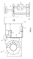
figure 5 , a possible embodiment of aconverter 12 will now be described by way of example, in this case of the single-phase type, i.e. having the first input/output interface connected to asingle module 2 of the electromagnetic device 1 (diagrammatically shown here with an equivalent inductance). Changes which will be apparent for a person skilled in art are to be made if a poly-phase interface is required. -
Converter 12 comprises abridge circuit 25 of the single-phase type consisting (in a known manner, here not described in detail) of an appropriate configuration of controlledswitches 26, each made with a respective semiconductor power device (e.g. a power transistor). - The
bridge circuit 25 has: a first a pair of interface terminals Int1, Int2, between which therespective module 2 is connected and between which an alternating voltage VAC is present; and a second pair of interface terminals Int3, Int4, between which acapacitor element 27 is connected, having local energy storage function, and between which a direct voltage VDC is present. - In particular, the second pair of interface terminals Int3, Int4 and the
capacitor element 27 are additionally connected to theDC bus 14. - The
local control unit 21 supplies appropriate control signals, for example PWM (Pulse Width Modulation) control signals, to the controlled switches 26, by means of the interposition of appropriate control modules (drivers) 28. -
Converter 12 further comprises: appropriateAC feedback sensors 29a, and appropriateDC feedback sensors 29b, including voltage and current sensors, coupled to the first pair of interface terminals Int1, Int2 and to the second pair of interface terminals Int3, Int4, respectively;converter 12 further comprisesappropriate temperature sensors 29c. - The PWM control signals and the feedback signals from the sensors (current, voltage and temperature measurements) are managed by the
local control unit 21 and are made available to the central control unit 20 (if present) and/or to thelocal control unit 21 of theother converters 12 of theconversion system 10, on communication buses or by interposing a sharedmemory 30. - The
local control unit 21 may receive control signals from the outside according to which operating set points may be calculated and assigned, and according to which, for example, the PWM control signals may be generated. - In particular, the
bridge circuit 25 is configured to operate as a rectifier (both in active configuration and in passive configuration), if the associatedmodules 2 of theelectromagnetic device 1 operate as an electric generator, or as an inverter, if thesame modules 2 operate as an electric motor. - With reference to
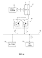
figure 6 , an exemplary use of theconversion system 10 for anelectromagnetic device 1 will now be described, having a first section consisting of a given number ofmodules 2, dedicated to the generation of electric energy, and a second section consisting of a respective number ofdifferent modules 2, dedicated to operation as an electric motor; the two sections, and therespective modules 2, operate simultaneously. - A mechanical power source, named
prime mover 32, is coupled to the electromagnetic device 1 (alternatively, the mechanical power source may be the fluid which activates the impeller of a turbine, where theelectromagnetic device 1 is integrated in the impeller). - As previously shown, the number of
modules 2 dedicated to generation of electric energy and to operation as an electric motor may be varied and configured either offline (statically) or online (dynamically) according to the operating needs of theelectromagnetic device 1 and/or of theconversion system 10. - In the illustrated embodiment, the first section of the
electromagnetic device 1 may advantageously supply the load, for example consisting of aDC load 16 of the resistive type, the following relation being effective:
IG = IL
where IG is the electric current supplied by the first section, operating as an electric generator, and IL is the current supplied to theDC load 16. - The propulsive power for the second section of
device 1 is instead supplied by theenergy storage device 19, the following relation being effective:
IM = IS
where IM is the electric current supplied to the second section, operating as an electric generator, and Is is the current supplied by theenergy storage device 19. - The configuration illustrated in
figure 6 may be advantageous in applications where a mechanical power boost is required; for example, in an aircraft, the main role of the electric machine is to convert part of the mechanical energy generated by the propulsion engine into electric energy for supplying the loads; a mechanical power boost may be supplied to the propulsion engine during take-off by reconfiguring part of the electromagnetic device and utilizing part of the electric machine as a motor. - In particular, both generator and electric motor sections being contained in the
electromagnetic device 1 itself allows an obvious reduction of weight, because both sections share the "heavy" parts, such asrotor 3,rotating shaft 4 andcasing 8. - The advantages of the described solution are clear from the above discussion.
- In particular, such a solution allows to use the
electromagnetic device 1 both as a generator and as an electric motor in an intelligent, totally configurable manner, also in real time (online) in addition to during the step of designing (offline). In particular, simultaneous operation as a generator/motor of first and, respectively,second modules 2 forming theelectromagnetic device 1 is possible. - Furthermore, the DC conversion of the single-phase (or poly-phase) electric quantities generated by the
modules 2 of theelectromagnetic device 1 allows to overcome the limitation related to the isomorphism of the electric quantities to be combined, because the combination of the contributions of eachmodule 2 is no longer in AC, where it is important to ensure equality of amplitude, frequency and phase, but in DC, where adjusting the amplitude is sufficient. In particular, the problem of the misalignment ofmodules 2 and of the variability of the gap is solved electronically, and not longer by means of mechanical calibration. - With this regard, reference can be made to
figures 7-9 which show some possible misalignment situations caused by manufacturing tolerances, for example. - In detail,
figures 7a and 7b diagrammatically show the result of a possible variability, indicated by δg1, δg2, in the gap g betweenrotor 3 and magnetic yoke 5 (figure 7a shows the nominal design situation). -
Figures 8a-8d diagrammatically show the result of an imperfect alignment between thepolar expansions magnetic yoke 5, in particular,figures 8b and 8c , in the form of an angular displacement δγ1, δγ2 with respect to a nominal angle γ0 (figure 8a ) of the symmetry axis (c being the center of rotor 3); alternatively,figure 8d shows an angular displacement δϕ of the position of the entiremagnetic yoke 5. -
Figures 9a and 9b diagrammatically show the result of a radial misalignment (figure 9a ), or on the horizontal plane (figure 9b ), (displacement δx and δy along a first and a second horizontal axis x, y) of thepolar expansions - The aforesaid feature results in the advantage of not requiring the intervention of a specialized operator having the equipment needed for calibration and does not require machine downtime for implementing corrective actions because these are carried out electronically by automatically controlling the DC voltage, resulting from the conversion of the single/poly-phase quantities generated by the single modules/groups of modules (and by leveling the amplitudes by the capacitive contribution associated with the DC bus 14).
- The present solution generally allows to increase the efficiency of the
conversion system 10 and to release the constraints and manufacturing tolerances of the modular electric machines by eliminating the phenomenon of recirculation currents caused by the lack of isomorphism of the electromagnetic quantities. - In other words, the suggested solution allows to solve the problems related to constructive asymmetries caused by mechanical manufacturing tolerances (translation and/or rotation), which do not result, in this solution, in the generation of recirculation currents in the modules (or cells) connected in parallel to one another. Indeed, by independently DC converting the contribution of each cell, the need to connect several cells in parallel to one another no longer exists. Possible differences in amplitude, frequency and phase of the alternating quantities output by the cells liable to manufacturing tolerances are no longer present in the DC converted quantities which are sent onto the common DC bus, where it is sufficient to adjust only the amplitude of the output quantities from the AC/DC converters in order to avoid the generation of recirculation currents.
- The suggested solution also allows to increase the reliability of the
energy conversion system 10 and its fault resistance; indeed, the number of independent conversion branches is equal to the number ofmodules 2 of theelectromagnetic device 1, thus greatly increasing the number of admissible faults. - Furthermore, the intrinsic modularity of the
electromagnetic device 1 effectively ensures the physical and magnetic insulation of thevarious modules 2, and therefore the possibility of fault propagation is minimized. - The presence of the
DC network 15, onto which an appropriateenergy storage device 19 is to be connected, for example in the form of one or more battery packs, further provides an emergency system for supplying the loads in case of total failure of theconversion system 10. - The suggested solution also allows to obtain clear reductions of weight, dimensions and general complexity of the
conversion system 10, and an increase of efficiency and flexibility of use of thesame conversion system 10. - It is finally apparent that changes and variations can be made to the embodiments described and illustrated herein, without departing from the scope of the present invention, as defined in the appended claims.
- In particular, it is apparent that the circuit structure of the
single converters 12 may differ from the above disclosure given by way of example. - Moreover, although the
conversion system 10 is advantageously applicable to anelectromagnetic device 1 of the previously described type, it is apparent that thesame conversion system 10 may operate with different types of electric machines; in particular, the configuration of the electric machine may differ from the above-disclosed embodiments given by way of example.
Claims (16)
- A power conversion system (10), for a modular electromagnetic device (1) provided with a plurality of modules (2) having reversible operation, operable either as generator or as electric motor, characterized by having a modular structure and by comprising:a plurality of converters (12), each designed to be connected to an assignable number of said modules; andcontrol means (20; 21), designed to configure said power conversion system (10), statically and/or dynamically during its operation, by defining the assignment between said converters (12) and a respective number of said modules (2), and/or the operation as generator, or as electric motor, of said modules (2).
- The system according to claim 1, wherein at least one first converter (12) is configurable by said control means (20; 21) to be assigned to a respective number of first converters (12), operating as electric generators; and at least one second converter (12) is simultaneously configurable by said control means (20; 21) to be assigned to a respective number of second converters (12), different from said first converters (12), operating as electric motors.
- The system according to claim 1 or 2, wherein said control means (20; 21) are further configured to selectively activate or deactivate the operation of one or more of said modules (2), even in real time, based on the determination of at least one operating parameter of said modules (2).
- The system according to any one of the preceding claims, wherein said converters (12) are configured to perform an alternating current/direct current conversion - AC/DC conversion - of at least one respective electrical quantity associated to the respective modules (2); further comprising a DC bus (14) to which said converters (12) are connected in a shared manner.
- The system according to claim 4, wherein said converters (12) have DC interfaces connected in parallel to each other and to the DC bus (14), so that respective DC electric quantities associated to said converters (12) are combinable on said DC bus (14), under control of said control means (20; 21).
- The system according to claim 4 or 5, wherein said DC bus (14) is of the capacitive type; further comprising a DC network (15) associated to said DC bus (14), to which one or more DC loads (16), and/or one or more AC loads (17) with the interposition of respective DC/AC converters (18), are designed to be connected.
- The system according to any one of claims 4-6, further comprising an energy storage device (19), connected to said DC network (15).
- The system according to any one of the preceding claims, wherein each one of said converters (12) is selectively assignable to a respective one of said modules (2), with a single-phase coupling interface.
- The system according to any one of the preceding claims, wherein said control means include a central control unit (20) connected to, and designed to provide control signals to said converters (12).
- The system according to any one of the preceding claims, wherein each one of said converters (12) includes a respective local control unit (21); the local control units (21) of said converters (12) being connected to each other by a communication bus (24).
- A modular electromagnetic device (1) comprising a plurality of modules (2) having reversible operation, each of which operable either as generator or as electric motor, and the power conversion system (10) according to any one of the preceding claims.
- The device according to claim 11, wherein said modules (2) are mutually independent and have autonomously configurable operation; and wherein one or more of first modules among said modules (2) are designed to operate as generators, and one or more of second modules among said modules (2) are simultaneously designed to operate as electric motors.
- The device according to claim 12, comprising a rotor (3), carrying a plurality of magnets; wherein each of said modules (2) comprises at least one magnetic yoke (5), having polar expansions (6a, 6b), about which a respective coil is wound, arranged facing a respective pair of said magnets; and wherein the coils wound about said polar expansions (6a, 6b) of each magnetic yoke (5) may individually be electrically coupled, alternatively to an electric power source or to an electric user, or load.
- The device according to claim 13, wherein each one of said magnetic yokes (5) is mounted on a respective support (7), the position of which is independently adjustable, axially and radially with respect to the rotor (3), so as to allow a static and/or dynamic adjustment of the gap between the respective polar expansions (6a, 6b) and the respective magnets.
- The device according to any one of the claims 11-14, wherein said power conversion system (10) comprises a plurality of converters (12) configured to operate an alternating current/direct current conversion - AC/DC conversion - of at least one respective electric quantity associated to respective ones of said modules (2), and furthermore a DC bus (14) to which said converters (12) are connected in a shared manner; and wherein said power conversion system (10) is configured to electronically compensate for possible constructive asymmetries of said modules (2) due to manufacturing tolerances.
- The device according to any one of the claims 11-15, comprising a casing (8), in which said modules (2) and, jointly, said conversion system (10) are assembled in an integrated manner.
Applications Claiming Priority (1)
| Application Number | Priority Date | Filing Date | Title |
|---|---|---|---|
| IT000599A ITTO20130599A1 (en) | 2013-07-16 | 2013-07-16 | MODULAR ELECTRIC POWER CONVERSION SYSTEM FOR A REVERSIBLE ELECTROMAGNETIC DEVICE |
Publications (3)
| Publication Number | Publication Date |
|---|---|
| EP2830190A2 true EP2830190A2 (en) | 2015-01-28 |
| EP2830190A3 EP2830190A3 (en) | 2015-06-24 |
| EP2830190B1 EP2830190B1 (en) | 2019-08-28 |
Family
ID=49182432
Family Applications (1)
| Application Number | Title | Priority Date | Filing Date |
|---|---|---|---|
| EP14177346.5A Active EP2830190B1 (en) | 2013-07-16 | 2014-07-16 | Modular electric power conversion system for a reversible electromagnetic device |
Country Status (2)
| Country | Link |
|---|---|
| EP (1) | EP2830190B1 (en) |
| IT (1) | ITTO20130599A1 (en) |
Cited By (1)
| Publication number | Priority date | Publication date | Assignee | Title |
|---|---|---|---|---|
| CN110945747A (en) * | 2017-01-31 | 2020-03-31 | 雷勃澳大利亚私人有限公司 | Modular stator drive unit for axial flux motors |
Families Citing this family (1)
| Publication number | Priority date | Publication date | Assignee | Title |
|---|---|---|---|---|
| US12592573B2 (en) | 2021-05-24 | 2026-03-31 | Discovery Energy, Llc | Hybrid generator with detachable power unit and panel integration |
Citations (1)
| Publication number | Priority date | Publication date | Assignee | Title |
|---|---|---|---|---|
| WO2009093181A2 (en) | 2008-01-21 | 2009-07-30 | Marco Cipriani | Electromagnetic device with reversible generator-motor operation |
Family Cites Families (2)
| Publication number | Priority date | Publication date | Assignee | Title |
|---|---|---|---|---|
| US5514923A (en) * | 1990-05-03 | 1996-05-07 | Gossler; Scott E. | High efficiency DC motor with generator and flywheel characteristics |
| US7248006B2 (en) * | 2002-07-01 | 2007-07-24 | Xidem, Inc. | Electronically controlled electric motor |
-
2013
- 2013-07-16 IT IT000599A patent/ITTO20130599A1/en unknown
-
2014
- 2014-07-16 EP EP14177346.5A patent/EP2830190B1/en active Active
Patent Citations (2)
| Publication number | Priority date | Publication date | Assignee | Title |
|---|---|---|---|---|
| WO2009093181A2 (en) | 2008-01-21 | 2009-07-30 | Marco Cipriani | Electromagnetic device with reversible generator-motor operation |
| WO2009093183A2 (en) | 2008-01-21 | 2009-07-30 | Marco Cipriani | Modular electromagnetic device with reversible generator-motor operation |
Cited By (3)
| Publication number | Priority date | Publication date | Assignee | Title |
|---|---|---|---|---|
| CN110945747A (en) * | 2017-01-31 | 2020-03-31 | 雷勃澳大利亚私人有限公司 | Modular stator drive unit for axial flux motors |
| EP3574566A4 (en) * | 2017-01-31 | 2020-11-25 | Regal Beloit Australia Pty Ltd. | MODULAR STATOR DRIVE UNITS FOR AXIAL FLOW MACHINES |
| CN110945747B (en) * | 2017-01-31 | 2022-03-18 | 雷勃澳大利亚私人有限公司 | Modular stator drive unit for axial flux electric machine |
Also Published As
| Publication number | Publication date |
|---|---|
| ITTO20130599A1 (en) | 2015-01-17 |
| EP2830190A3 (en) | 2015-06-24 |
| EP2830190B1 (en) | 2019-08-28 |
Similar Documents
| Publication | Publication Date | Title |
|---|---|---|
| CN105576921B (en) | Dynamically reconfigurable motor, electric system and motor dynamics reconstructing method | |
| US9991719B2 (en) | Systems and methods for reducing circulating current and phase to phase imbalance in a parallel modular converter system | |
| EP3012704B1 (en) | Parallel modular converter architecture | |
| US10566922B2 (en) | Dynamically reconfigurable motors and generators and systems with efficiency optimization | |
| WO2021074661A1 (en) | Multibridge power converter with multiple outputs | |
| EP4380815A2 (en) | Systems, devices, and methods for charging and discharging module-based cascaded energy systems | |
| US10486537B2 (en) | Power generating systems having synchronous generator multiplex windings and multilevel inverters | |
| EP3928411B1 (en) | Integrated charger and motor control system isolated by motor | |
| KR102202514B1 (en) | Electronic architecture for controlling a dc/ac voltage converter | |
| EP1317057A2 (en) | An aerospace generator arrangement | |
| CN103765756A (en) | System for controlling a rotating electric machine to reduce current ripple on a DC bus | |
| CN102340255A (en) | Power layer generation of inverter gate drive signals | |
| JP6844716B2 (en) | Inverter control board | |
| CN104426444A (en) | Aircraft Engine Constant Frequency Starter/generator | |
| JP2024518547A (en) | Dynamically configurable hardware system for a motor system and method of operation thereof - Patents.com | |
| JP2015509698A (en) | How to use the electrical unit | |
| EP3788696A1 (en) | Dual transformer turbine | |
| JP2020202722A (en) | Power conversion device | |
| US11539305B2 (en) | Modular arrangement of a converter and aircraft having a modular arrangement | |
| EP2830190B1 (en) | Modular electric power conversion system for a reversible electromagnetic device | |
| EP1926202B1 (en) | Power conversion apparatus | |
| US10855214B2 (en) | Electrical powertrain for aircraft | |
| CN115362079B (en) | Motor system | |
| EP2741414B1 (en) | System and Method for Optimization of Dual Bridge Doubly Fed Induction Generator (DFIG) | |
| CN112534131A (en) | Wind turbine pitch system |
Legal Events
| Date | Code | Title | Description |
|---|---|---|---|
| 17P | Request for examination filed |
Effective date: 20140716 |
|
| AK | Designated contracting states |
Kind code of ref document: A2 Designated state(s): AL AT BE BG CH CY CZ DE DK EE ES FI FR GB GR HR HU IE IS IT LI LT LU LV MC MK MT NL NO PL PT RO RS SE SI SK SM TR |
|
| AX | Request for extension of the european patent |
Extension state: BA ME |
|
| PUAI | Public reference made under article 153(3) epc to a published international application that has entered the european phase |
Free format text: ORIGINAL CODE: 0009012 |
|
| PUAL | Search report despatched |
Free format text: ORIGINAL CODE: 0009013 |
|
| AK | Designated contracting states |
Kind code of ref document: A3 Designated state(s): AL AT BE BG CH CY CZ DE DK EE ES FI FR GB GR HR HU IE IS IT LI LT LU LV MC MK MT NL NO PL PT RO RS SE SI SK SM TR |
|
| AX | Request for extension of the european patent |
Extension state: BA ME |
|
| RIC1 | Information provided on ipc code assigned before grant |
Ipc: H02P 6/14 20060101ALI20150521BHEP Ipc: H02K 21/24 20060101ALI20150521BHEP Ipc: H02J 7/14 20060101AFI20150521BHEP Ipc: H02K 11/00 20060101ALN20150521BHEP Ipc: H02K 1/14 20060101ALN20150521BHEP |
|
| R17P | Request for examination filed (corrected) |
Effective date: 20151222 |
|
| RBV | Designated contracting states (corrected) |
Designated state(s): AL AT BE BG CH CY CZ DE DK EE ES FI FR GB GR HR HU IE IS IT LI LT LU LV MC MK MT NL NO PL PT RO RS SE SI SK SM TR |
|
| STAA | Information on the status of an ep patent application or granted ep patent |
Free format text: STATUS: EXAMINATION IS IN PROGRESS |
|
| 17Q | First examination report despatched |
Effective date: 20180201 |
|
| GRAP | Despatch of communication of intention to grant a patent |
Free format text: ORIGINAL CODE: EPIDOSNIGR1 |
|
| STAA | Information on the status of an ep patent application or granted ep patent |
Free format text: STATUS: GRANT OF PATENT IS INTENDED |
|
| RIC1 | Information provided on ipc code assigned before grant |
Ipc: H02P 6/14 20160101ALI20181112BHEP Ipc: H02K 1/14 20060101ALN20181112BHEP Ipc: H02J 7/14 20060101AFI20181112BHEP Ipc: H02K 11/33 20160101ALN20181112BHEP Ipc: H02K 21/24 20060101ALI20181112BHEP |
|
| INTG | Intention to grant announced |
Effective date: 20181204 |
|
| RIC1 | Information provided on ipc code assigned before grant |
Ipc: H02K 1/14 20060101ALN20181112BHEP Ipc: H02P 6/14 20160101ALI20181112BHEP Ipc: H02J 7/14 20060101AFI20181112BHEP Ipc: H02K 11/33 20160101ALN20181112BHEP Ipc: H02K 21/24 20060101ALI20181112BHEP |
|
| GRAJ | Information related to disapproval of communication of intention to grant by the applicant or resumption of examination proceedings by the epo deleted |
Free format text: ORIGINAL CODE: EPIDOSDIGR1 |
|
| STAA | Information on the status of an ep patent application or granted ep patent |
Free format text: STATUS: EXAMINATION IS IN PROGRESS |
|
| INTC | Intention to grant announced (deleted) | ||
| GRAR | Information related to intention to grant a patent recorded |
Free format text: ORIGINAL CODE: EPIDOSNIGR71 |
|
| GRAS | Grant fee paid |
Free format text: ORIGINAL CODE: EPIDOSNIGR3 |
|
| STAA | Information on the status of an ep patent application or granted ep patent |
Free format text: STATUS: GRANT OF PATENT IS INTENDED |
|
| RIC1 | Information provided on ipc code assigned before grant |
Ipc: H02P 6/14 20160101ALI20190527BHEP Ipc: H02K 1/14 20060101ALN20190527BHEP Ipc: H02K 11/33 20160101ALN20190527BHEP Ipc: H02K 21/24 20060101ALI20190527BHEP Ipc: H02J 7/14 20060101AFI20190527BHEP |
|
| INTG | Intention to grant announced |
Effective date: 20190603 |
|
| GRAA | (expected) grant |
Free format text: ORIGINAL CODE: 0009210 |
|
| STAA | Information on the status of an ep patent application or granted ep patent |
Free format text: STATUS: THE PATENT HAS BEEN GRANTED |
|
| AK | Designated contracting states |
Kind code of ref document: B1 Designated state(s): AL AT BE BG CH CY CZ DE DK EE ES FI FR GB GR HR HU IE IS IT LI LT LU LV MC MK MT NL NO PL PT RO RS SE SI SK SM TR |
|
| REG | Reference to a national code |
Ref country code: GB Ref legal event code: FG4D |
|
| REG | Reference to a national code |
Ref country code: CH Ref legal event code: EP |
|
| REG | Reference to a national code |
Ref country code: AT Ref legal event code: REF Ref document number: 1173599 Country of ref document: AT Kind code of ref document: T Effective date: 20190915 |
|
| REG | Reference to a national code |
Ref country code: IE Ref legal event code: FG4D |
|
| REG | Reference to a national code |
Ref country code: DE Ref legal event code: R096 Ref document number: 602014052420 Country of ref document: DE |
|
| REG | Reference to a national code |
Ref country code: NL Ref legal event code: MP Effective date: 20190828 |
|
| REG | Reference to a national code |
Ref country code: LT Ref legal event code: MG4D |
|
| PG25 | Lapsed in a contracting state [announced via postgrant information from national office to epo] |
Ref country code: NO Free format text: LAPSE BECAUSE OF FAILURE TO SUBMIT A TRANSLATION OF THE DESCRIPTION OR TO PAY THE FEE WITHIN THE PRESCRIBED TIME-LIMIT Effective date: 20191128 Ref country code: SE Free format text: LAPSE BECAUSE OF FAILURE TO SUBMIT A TRANSLATION OF THE DESCRIPTION OR TO PAY THE FEE WITHIN THE PRESCRIBED TIME-LIMIT Effective date: 20190828 Ref country code: HR Free format text: LAPSE BECAUSE OF FAILURE TO SUBMIT A TRANSLATION OF THE DESCRIPTION OR TO PAY THE FEE WITHIN THE PRESCRIBED TIME-LIMIT Effective date: 20190828 Ref country code: PT Free format text: LAPSE BECAUSE OF FAILURE TO SUBMIT A TRANSLATION OF THE DESCRIPTION OR TO PAY THE FEE WITHIN THE PRESCRIBED TIME-LIMIT Effective date: 20191230 Ref country code: LT Free format text: LAPSE BECAUSE OF FAILURE TO SUBMIT A TRANSLATION OF THE DESCRIPTION OR TO PAY THE FEE WITHIN THE PRESCRIBED TIME-LIMIT Effective date: 20190828 Ref country code: FI Free format text: LAPSE BECAUSE OF FAILURE TO SUBMIT A TRANSLATION OF THE DESCRIPTION OR TO PAY THE FEE WITHIN THE PRESCRIBED TIME-LIMIT Effective date: 20190828 Ref country code: BG Free format text: LAPSE BECAUSE OF FAILURE TO SUBMIT A TRANSLATION OF THE DESCRIPTION OR TO PAY THE FEE WITHIN THE PRESCRIBED TIME-LIMIT Effective date: 20191128 Ref country code: NL Free format text: LAPSE BECAUSE OF FAILURE TO SUBMIT A TRANSLATION OF THE DESCRIPTION OR TO PAY THE FEE WITHIN THE PRESCRIBED TIME-LIMIT Effective date: 20190828 |
|
| PG25 | Lapsed in a contracting state [announced via postgrant information from national office to epo] |
Ref country code: AL Free format text: LAPSE BECAUSE OF FAILURE TO SUBMIT A TRANSLATION OF THE DESCRIPTION OR TO PAY THE FEE WITHIN THE PRESCRIBED TIME-LIMIT Effective date: 20190828 Ref country code: LV Free format text: LAPSE BECAUSE OF FAILURE TO SUBMIT A TRANSLATION OF THE DESCRIPTION OR TO PAY THE FEE WITHIN THE PRESCRIBED TIME-LIMIT Effective date: 20190828 Ref country code: ES Free format text: LAPSE BECAUSE OF FAILURE TO SUBMIT A TRANSLATION OF THE DESCRIPTION OR TO PAY THE FEE WITHIN THE PRESCRIBED TIME-LIMIT Effective date: 20190828 Ref country code: GR Free format text: LAPSE BECAUSE OF FAILURE TO SUBMIT A TRANSLATION OF THE DESCRIPTION OR TO PAY THE FEE WITHIN THE PRESCRIBED TIME-LIMIT Effective date: 20191129 Ref country code: IS Free format text: LAPSE BECAUSE OF FAILURE TO SUBMIT A TRANSLATION OF THE DESCRIPTION OR TO PAY THE FEE WITHIN THE PRESCRIBED TIME-LIMIT Effective date: 20191228 Ref country code: RS Free format text: LAPSE BECAUSE OF FAILURE TO SUBMIT A TRANSLATION OF THE DESCRIPTION OR TO PAY THE FEE WITHIN THE PRESCRIBED TIME-LIMIT Effective date: 20190828 |
|
| REG | Reference to a national code |
Ref country code: AT Ref legal event code: MK05 Ref document number: 1173599 Country of ref document: AT Kind code of ref document: T Effective date: 20190828 |
|
| PG25 | Lapsed in a contracting state [announced via postgrant information from national office to epo] |
Ref country code: TR Free format text: LAPSE BECAUSE OF FAILURE TO SUBMIT A TRANSLATION OF THE DESCRIPTION OR TO PAY THE FEE WITHIN THE PRESCRIBED TIME-LIMIT Effective date: 20190828 |
|
| PG25 | Lapsed in a contracting state [announced via postgrant information from national office to epo] |
Ref country code: IT Free format text: LAPSE BECAUSE OF FAILURE TO SUBMIT A TRANSLATION OF THE DESCRIPTION OR TO PAY THE FEE WITHIN THE PRESCRIBED TIME-LIMIT Effective date: 20190828 Ref country code: RO Free format text: LAPSE BECAUSE OF FAILURE TO SUBMIT A TRANSLATION OF THE DESCRIPTION OR TO PAY THE FEE WITHIN THE PRESCRIBED TIME-LIMIT Effective date: 20190828 Ref country code: PL Free format text: LAPSE BECAUSE OF FAILURE TO SUBMIT A TRANSLATION OF THE DESCRIPTION OR TO PAY THE FEE WITHIN THE PRESCRIBED TIME-LIMIT Effective date: 20190828 Ref country code: DK Free format text: LAPSE BECAUSE OF FAILURE TO SUBMIT A TRANSLATION OF THE DESCRIPTION OR TO PAY THE FEE WITHIN THE PRESCRIBED TIME-LIMIT Effective date: 20190828 Ref country code: EE Free format text: LAPSE BECAUSE OF FAILURE TO SUBMIT A TRANSLATION OF THE DESCRIPTION OR TO PAY THE FEE WITHIN THE PRESCRIBED TIME-LIMIT Effective date: 20190828 Ref country code: AT Free format text: LAPSE BECAUSE OF FAILURE TO SUBMIT A TRANSLATION OF THE DESCRIPTION OR TO PAY THE FEE WITHIN THE PRESCRIBED TIME-LIMIT Effective date: 20190828 |
|
| PG25 | Lapsed in a contracting state [announced via postgrant information from national office to epo] |
Ref country code: IS Free format text: LAPSE BECAUSE OF FAILURE TO SUBMIT A TRANSLATION OF THE DESCRIPTION OR TO PAY THE FEE WITHIN THE PRESCRIBED TIME-LIMIT Effective date: 20200224 Ref country code: SM Free format text: LAPSE BECAUSE OF FAILURE TO SUBMIT A TRANSLATION OF THE DESCRIPTION OR TO PAY THE FEE WITHIN THE PRESCRIBED TIME-LIMIT Effective date: 20190828 Ref country code: SK Free format text: LAPSE BECAUSE OF FAILURE TO SUBMIT A TRANSLATION OF THE DESCRIPTION OR TO PAY THE FEE WITHIN THE PRESCRIBED TIME-LIMIT Effective date: 20190828 Ref country code: CZ Free format text: LAPSE BECAUSE OF FAILURE TO SUBMIT A TRANSLATION OF THE DESCRIPTION OR TO PAY THE FEE WITHIN THE PRESCRIBED TIME-LIMIT Effective date: 20190828 |
|
| REG | Reference to a national code |
Ref country code: DE Ref legal event code: R097 Ref document number: 602014052420 Country of ref document: DE |
|
| PLBE | No opposition filed within time limit |
Free format text: ORIGINAL CODE: 0009261 |
|
| STAA | Information on the status of an ep patent application or granted ep patent |
Free format text: STATUS: NO OPPOSITION FILED WITHIN TIME LIMIT |
|
| PG2D | Information on lapse in contracting state deleted |
Ref country code: IS |
|
| 26N | No opposition filed |
Effective date: 20200603 |
|
| PG25 | Lapsed in a contracting state [announced via postgrant information from national office to epo] |
Ref country code: SI Free format text: LAPSE BECAUSE OF FAILURE TO SUBMIT A TRANSLATION OF THE DESCRIPTION OR TO PAY THE FEE WITHIN THE PRESCRIBED TIME-LIMIT Effective date: 20190828 |
|
| PG25 | Lapsed in a contracting state [announced via postgrant information from national office to epo] |
Ref country code: MC Free format text: LAPSE BECAUSE OF FAILURE TO SUBMIT A TRANSLATION OF THE DESCRIPTION OR TO PAY THE FEE WITHIN THE PRESCRIBED TIME-LIMIT Effective date: 20190828 |
|
| REG | Reference to a national code |
Ref country code: CH Ref legal event code: PL |
|
| REG | Reference to a national code |
Ref country code: BE Ref legal event code: MM Effective date: 20200731 |
|
| PG25 | Lapsed in a contracting state [announced via postgrant information from national office to epo] |
Ref country code: CH Free format text: LAPSE BECAUSE OF NON-PAYMENT OF DUE FEES Effective date: 20200731 Ref country code: LI Free format text: LAPSE BECAUSE OF NON-PAYMENT OF DUE FEES Effective date: 20200731 Ref country code: LU Free format text: LAPSE BECAUSE OF NON-PAYMENT OF DUE FEES Effective date: 20200716 |
|
| PG25 | Lapsed in a contracting state [announced via postgrant information from national office to epo] |
Ref country code: BE Free format text: LAPSE BECAUSE OF NON-PAYMENT OF DUE FEES Effective date: 20200731 |
|
| PG25 | Lapsed in a contracting state [announced via postgrant information from national office to epo] |
Ref country code: IE Free format text: LAPSE BECAUSE OF NON-PAYMENT OF DUE FEES Effective date: 20200716 |
|
| PG25 | Lapsed in a contracting state [announced via postgrant information from national office to epo] |
Ref country code: MT Free format text: LAPSE BECAUSE OF FAILURE TO SUBMIT A TRANSLATION OF THE DESCRIPTION OR TO PAY THE FEE WITHIN THE PRESCRIBED TIME-LIMIT Effective date: 20190828 Ref country code: CY Free format text: LAPSE BECAUSE OF FAILURE TO SUBMIT A TRANSLATION OF THE DESCRIPTION OR TO PAY THE FEE WITHIN THE PRESCRIBED TIME-LIMIT Effective date: 20190828 |
|
| PG25 | Lapsed in a contracting state [announced via postgrant information from national office to epo] |
Ref country code: MK Free format text: LAPSE BECAUSE OF FAILURE TO SUBMIT A TRANSLATION OF THE DESCRIPTION OR TO PAY THE FEE WITHIN THE PRESCRIBED TIME-LIMIT Effective date: 20190828 |
|
| P01 | Opt-out of the competence of the unified patent court (upc) registered |
Effective date: 20230418 |
|
| PGFP | Annual fee paid to national office [announced via postgrant information from national office to epo] |
Ref country code: GB Payment date: 20250619 Year of fee payment: 12 |
|
| PGFP | Annual fee paid to national office [announced via postgrant information from national office to epo] |
Ref country code: FR Payment date: 20250620 Year of fee payment: 12 |
|
| PGFP | Annual fee paid to national office [announced via postgrant information from national office to epo] |
Ref country code: DE Payment date: 20250620 Year of fee payment: 12 |