EP2830167A1 - Connector fixing structure and method of manufacturing the same - Google Patents
Connector fixing structure and method of manufacturing the same Download PDFInfo
- Publication number
- EP2830167A1 EP2830167A1 EP20140170694 EP14170694A EP2830167A1 EP 2830167 A1 EP2830167 A1 EP 2830167A1 EP 20140170694 EP20140170694 EP 20140170694 EP 14170694 A EP14170694 A EP 14170694A EP 2830167 A1 EP2830167 A1 EP 2830167A1
- Authority
- EP
- European Patent Office
- Prior art keywords
- housing
- connector
- insertion opening
- opening member
- side insertion
- Prior art date
- Legal status (The legal status is an assumption and is not a legal conclusion. Google has not performed a legal analysis and makes no representation as to the accuracy of the status listed.)
- Granted
Links
Images



Classifications
-
- H—ELECTRICITY
- H01—ELECTRIC ELEMENTS
- H01R—ELECTRICALLY-CONDUCTIVE CONNECTIONS; STRUCTURAL ASSOCIATIONS OF A PLURALITY OF MUTUALLY-INSULATED ELECTRICAL CONNECTING ELEMENTS; COUPLING DEVICES; CURRENT COLLECTORS
- H01R13/00—Details of coupling devices of the kinds covered by groups H01R12/70 or H01R24/00 - H01R33/00
- H01R13/46—Bases; Cases
- H01R13/52—Dustproof, splashproof, drip-proof, waterproof, or flameproof cases
- H01R13/5202—Sealing means between parts of housing or between housing part and a wall, e.g. sealing rings
-
- B—PERFORMING OPERATIONS; TRANSPORTING
- B29—WORKING OF PLASTICS; WORKING OF SUBSTANCES IN A PLASTIC STATE IN GENERAL
- B29C—SHAPING OR JOINING OF PLASTICS; SHAPING OF MATERIAL IN A PLASTIC STATE, NOT OTHERWISE PROVIDED FOR; AFTER-TREATMENT OF THE SHAPED PRODUCTS, e.g. REPAIRING
- B29C65/00—Joining or sealing of preformed parts, e.g. welding of plastics materials; Apparatus therefor
- B29C65/02—Joining or sealing of preformed parts, e.g. welding of plastics materials; Apparatus therefor by heating, with or without pressure
- B29C65/14—Joining or sealing of preformed parts, e.g. welding of plastics materials; Apparatus therefor by heating, with or without pressure using wave energy, i.e. electromagnetic radiation, or particle radiation
- B29C65/16—Laser beams
-
- H—ELECTRICITY
- H01—ELECTRIC ELEMENTS
- H01R—ELECTRICALLY-CONDUCTIVE CONNECTIONS; STRUCTURAL ASSOCIATIONS OF A PLURALITY OF MUTUALLY-INSULATED ELECTRICAL CONNECTING ELEMENTS; COUPLING DEVICES; CURRENT COLLECTORS
- H01R13/00—Details of coupling devices of the kinds covered by groups H01R12/70 or H01R24/00 - H01R33/00
- H01R13/46—Bases; Cases
-
- H—ELECTRICITY
- H01—ELECTRIC ELEMENTS
- H01R—ELECTRICALLY-CONDUCTIVE CONNECTIONS; STRUCTURAL ASSOCIATIONS OF A PLURALITY OF MUTUALLY-INSULATED ELECTRICAL CONNECTING ELEMENTS; COUPLING DEVICES; CURRENT COLLECTORS
- H01R13/00—Details of coupling devices of the kinds covered by groups H01R12/70 or H01R24/00 - H01R33/00
- H01R13/73—Means for mounting coupling parts to apparatus or structures, e.g. to a wall
- H01R13/74—Means for mounting coupling parts in openings of a panel
-
- H—ELECTRICITY
- H01—ELECTRIC ELEMENTS
- H01R—ELECTRICALLY-CONDUCTIVE CONNECTIONS; STRUCTURAL ASSOCIATIONS OF A PLURALITY OF MUTUALLY-INSULATED ELECTRICAL CONNECTING ELEMENTS; COUPLING DEVICES; CURRENT COLLECTORS
- H01R43/00—Apparatus or processes specially adapted for manufacturing, assembling, maintaining, or repairing of line connectors or current collectors or for joining electric conductors
- H01R43/005—Apparatus or processes specially adapted for manufacturing, assembling, maintaining, or repairing of line connectors or current collectors or for joining electric conductors for making dustproof, splashproof, drip-proof, waterproof, or flameproof connection, coupling, or casing
-
- H—ELECTRICITY
- H01—ELECTRIC ELEMENTS
- H01R—ELECTRICALLY-CONDUCTIVE CONNECTIONS; STRUCTURAL ASSOCIATIONS OF A PLURALITY OF MUTUALLY-INSULATED ELECTRICAL CONNECTING ELEMENTS; COUPLING DEVICES; CURRENT COLLECTORS
- H01R43/00—Apparatus or processes specially adapted for manufacturing, assembling, maintaining, or repairing of line connectors or current collectors or for joining electric conductors
- H01R43/02—Apparatus or processes specially adapted for manufacturing, assembling, maintaining, or repairing of line connectors or current collectors or for joining electric conductors for soldered or welded connections
-
- B—PERFORMING OPERATIONS; TRANSPORTING
- B29—WORKING OF PLASTICS; WORKING OF SUBSTANCES IN A PLASTIC STATE IN GENERAL
- B29C—SHAPING OR JOINING OF PLASTICS; SHAPING OF MATERIAL IN A PLASTIC STATE, NOT OTHERWISE PROVIDED FOR; AFTER-TREATMENT OF THE SHAPED PRODUCTS, e.g. REPAIRING
- B29C65/00—Joining or sealing of preformed parts, e.g. welding of plastics materials; Apparatus therefor
- B29C65/02—Joining or sealing of preformed parts, e.g. welding of plastics materials; Apparatus therefor by heating, with or without pressure
- B29C65/08—Joining or sealing of preformed parts, e.g. welding of plastics materials; Apparatus therefor by heating, with or without pressure using ultrasonic vibrations
-
- B—PERFORMING OPERATIONS; TRANSPORTING
- B29—WORKING OF PLASTICS; WORKING OF SUBSTANCES IN A PLASTIC STATE IN GENERAL
- B29C—SHAPING OR JOINING OF PLASTICS; SHAPING OF MATERIAL IN A PLASTIC STATE, NOT OTHERWISE PROVIDED FOR; AFTER-TREATMENT OF THE SHAPED PRODUCTS, e.g. REPAIRING
- B29C65/00—Joining or sealing of preformed parts, e.g. welding of plastics materials; Apparatus therefor
- B29C65/02—Joining or sealing of preformed parts, e.g. welding of plastics materials; Apparatus therefor by heating, with or without pressure
- B29C65/14—Joining or sealing of preformed parts, e.g. welding of plastics materials; Apparatus therefor by heating, with or without pressure using wave energy, i.e. electromagnetic radiation, or particle radiation
- B29C65/16—Laser beams
- B29C65/1629—Laser beams characterised by the way of heating the interface
- B29C65/1635—Laser beams characterised by the way of heating the interface at least passing through one of the parts to be joined, i.e. laser transmission welding
-
- B—PERFORMING OPERATIONS; TRANSPORTING
- B29—WORKING OF PLASTICS; WORKING OF SUBSTANCES IN A PLASTIC STATE IN GENERAL
- B29C—SHAPING OR JOINING OF PLASTICS; SHAPING OF MATERIAL IN A PLASTIC STATE, NOT OTHERWISE PROVIDED FOR; AFTER-TREATMENT OF THE SHAPED PRODUCTS, e.g. REPAIRING
- B29C65/00—Joining or sealing of preformed parts, e.g. welding of plastics materials; Apparatus therefor
- B29C65/02—Joining or sealing of preformed parts, e.g. welding of plastics materials; Apparatus therefor by heating, with or without pressure
- B29C65/14—Joining or sealing of preformed parts, e.g. welding of plastics materials; Apparatus therefor by heating, with or without pressure using wave energy, i.e. electromagnetic radiation, or particle radiation
- B29C65/16—Laser beams
- B29C65/1629—Laser beams characterised by the way of heating the interface
- B29C65/1674—Laser beams characterised by the way of heating the interface making use of laser diodes
-
- B—PERFORMING OPERATIONS; TRANSPORTING
- B29—WORKING OF PLASTICS; WORKING OF SUBSTANCES IN A PLASTIC STATE IN GENERAL
- B29C—SHAPING OR JOINING OF PLASTICS; SHAPING OF MATERIAL IN A PLASTIC STATE, NOT OTHERWISE PROVIDED FOR; AFTER-TREATMENT OF THE SHAPED PRODUCTS, e.g. REPAIRING
- B29C65/00—Joining or sealing of preformed parts, e.g. welding of plastics materials; Apparatus therefor
- B29C65/02—Joining or sealing of preformed parts, e.g. welding of plastics materials; Apparatus therefor by heating, with or without pressure
- B29C65/14—Joining or sealing of preformed parts, e.g. welding of plastics materials; Apparatus therefor by heating, with or without pressure using wave energy, i.e. electromagnetic radiation, or particle radiation
- B29C65/16—Laser beams
- B29C65/1677—Laser beams making use of an absorber or impact modifier
-
- B—PERFORMING OPERATIONS; TRANSPORTING
- B29—WORKING OF PLASTICS; WORKING OF SUBSTANCES IN A PLASTIC STATE IN GENERAL
- B29C—SHAPING OR JOINING OF PLASTICS; SHAPING OF MATERIAL IN A PLASTIC STATE, NOT OTHERWISE PROVIDED FOR; AFTER-TREATMENT OF THE SHAPED PRODUCTS, e.g. REPAIRING
- B29C66/00—General aspects of processes or apparatus for joining preformed parts
- B29C66/01—General aspects dealing with the joint area or with the area to be joined
- B29C66/05—Particular design of joint configurations
- B29C66/10—Particular design of joint configurations particular design of the joint cross-sections
- B29C66/12—Joint cross-sections combining only two joint-segments; Tongue and groove joints; Tenon and mortise joints; Stepped joint cross-sections
- B29C66/128—Stepped joint cross-sections
- B29C66/1282—Stepped joint cross-sections comprising at least one overlap joint-segment
-
- B—PERFORMING OPERATIONS; TRANSPORTING
- B29—WORKING OF PLASTICS; WORKING OF SUBSTANCES IN A PLASTIC STATE IN GENERAL
- B29C—SHAPING OR JOINING OF PLASTICS; SHAPING OF MATERIAL IN A PLASTIC STATE, NOT OTHERWISE PROVIDED FOR; AFTER-TREATMENT OF THE SHAPED PRODUCTS, e.g. REPAIRING
- B29C66/00—General aspects of processes or apparatus for joining preformed parts
- B29C66/01—General aspects dealing with the joint area or with the area to be joined
- B29C66/05—Particular design of joint configurations
- B29C66/10—Particular design of joint configurations particular design of the joint cross-sections
- B29C66/12—Joint cross-sections combining only two joint-segments; Tongue and groove joints; Tenon and mortise joints; Stepped joint cross-sections
- B29C66/128—Stepped joint cross-sections
- B29C66/1284—Stepped joint cross-sections comprising at least one butt joint-segment
- B29C66/12841—Stepped joint cross-sections comprising at least one butt joint-segment comprising at least two butt joint-segments
-
- B—PERFORMING OPERATIONS; TRANSPORTING
- B29—WORKING OF PLASTICS; WORKING OF SUBSTANCES IN A PLASTIC STATE IN GENERAL
- B29C—SHAPING OR JOINING OF PLASTICS; SHAPING OF MATERIAL IN A PLASTIC STATE, NOT OTHERWISE PROVIDED FOR; AFTER-TREATMENT OF THE SHAPED PRODUCTS, e.g. REPAIRING
- B29C66/00—General aspects of processes or apparatus for joining preformed parts
- B29C66/01—General aspects dealing with the joint area or with the area to be joined
- B29C66/05—Particular design of joint configurations
- B29C66/10—Particular design of joint configurations particular design of the joint cross-sections
- B29C66/14—Particular design of joint configurations particular design of the joint cross-sections the joint having the same thickness as the thickness of the parts to be joined
-
- B—PERFORMING OPERATIONS; TRANSPORTING
- B29—WORKING OF PLASTICS; WORKING OF SUBSTANCES IN A PLASTIC STATE IN GENERAL
- B29C—SHAPING OR JOINING OF PLASTICS; SHAPING OF MATERIAL IN A PLASTIC STATE, NOT OTHERWISE PROVIDED FOR; AFTER-TREATMENT OF THE SHAPED PRODUCTS, e.g. REPAIRING
- B29C66/00—General aspects of processes or apparatus for joining preformed parts
- B29C66/50—General aspects of joining tubular articles; General aspects of joining long products, i.e. bars or profiled elements; General aspects of joining single elements to tubular articles, hollow articles or bars; General aspects of joining several hollow-preforms to form hollow or tubular articles
- B29C66/61—Joining from or joining on the inside
-
- B—PERFORMING OPERATIONS; TRANSPORTING
- B29—WORKING OF PLASTICS; WORKING OF SUBSTANCES IN A PLASTIC STATE IN GENERAL
- B29C—SHAPING OR JOINING OF PLASTICS; SHAPING OF MATERIAL IN A PLASTIC STATE, NOT OTHERWISE PROVIDED FOR; AFTER-TREATMENT OF THE SHAPED PRODUCTS, e.g. REPAIRING
- B29C66/00—General aspects of processes or apparatus for joining preformed parts
- B29C66/70—General aspects of processes or apparatus for joining preformed parts characterised by the composition, physical properties or the structure of the material of the parts to be joined; Joining with non-plastics material
- B29C66/73—General aspects of processes or apparatus for joining preformed parts characterised by the composition, physical properties or the structure of the material of the parts to be joined; Joining with non-plastics material characterised by the intensive physical properties of the material of the parts to be joined, by the optical properties of the material of the parts to be joined, by the extensive physical properties of the parts to be joined, by the state of the material of the parts to be joined or by the material of the parts to be joined being a thermoplastic or a thermoset
- B29C66/737—General aspects of processes or apparatus for joining preformed parts characterised by the composition, physical properties or the structure of the material of the parts to be joined; Joining with non-plastics material characterised by the intensive physical properties of the material of the parts to be joined, by the optical properties of the material of the parts to be joined, by the extensive physical properties of the parts to be joined, by the state of the material of the parts to be joined or by the material of the parts to be joined being a thermoplastic or a thermoset characterised by the state of the material of the parts to be joined
- B29C66/7377—General aspects of processes or apparatus for joining preformed parts characterised by the composition, physical properties or the structure of the material of the parts to be joined; Joining with non-plastics material characterised by the intensive physical properties of the material of the parts to be joined, by the optical properties of the material of the parts to be joined, by the extensive physical properties of the parts to be joined, by the state of the material of the parts to be joined or by the material of the parts to be joined being a thermoplastic or a thermoset characterised by the state of the material of the parts to be joined amorphous, semi-crystalline or crystalline
- B29C66/73771—General aspects of processes or apparatus for joining preformed parts characterised by the composition, physical properties or the structure of the material of the parts to be joined; Joining with non-plastics material characterised by the intensive physical properties of the material of the parts to be joined, by the optical properties of the material of the parts to be joined, by the extensive physical properties of the parts to be joined, by the state of the material of the parts to be joined or by the material of the parts to be joined being a thermoplastic or a thermoset characterised by the state of the material of the parts to be joined amorphous, semi-crystalline or crystalline the to-be-joined area of at least one of the parts to be joined being amorphous
-
- B—PERFORMING OPERATIONS; TRANSPORTING
- B29—WORKING OF PLASTICS; WORKING OF SUBSTANCES IN A PLASTIC STATE IN GENERAL
- B29C—SHAPING OR JOINING OF PLASTICS; SHAPING OF MATERIAL IN A PLASTIC STATE, NOT OTHERWISE PROVIDED FOR; AFTER-TREATMENT OF THE SHAPED PRODUCTS, e.g. REPAIRING
- B29C66/00—General aspects of processes or apparatus for joining preformed parts
- B29C66/70—General aspects of processes or apparatus for joining preformed parts characterised by the composition, physical properties or the structure of the material of the parts to be joined; Joining with non-plastics material
- B29C66/73—General aspects of processes or apparatus for joining preformed parts characterised by the composition, physical properties or the structure of the material of the parts to be joined; Joining with non-plastics material characterised by the intensive physical properties of the material of the parts to be joined, by the optical properties of the material of the parts to be joined, by the extensive physical properties of the parts to be joined, by the state of the material of the parts to be joined or by the material of the parts to be joined being a thermoplastic or a thermoset
- B29C66/737—General aspects of processes or apparatus for joining preformed parts characterised by the composition, physical properties or the structure of the material of the parts to be joined; Joining with non-plastics material characterised by the intensive physical properties of the material of the parts to be joined, by the optical properties of the material of the parts to be joined, by the extensive physical properties of the parts to be joined, by the state of the material of the parts to be joined or by the material of the parts to be joined being a thermoplastic or a thermoset characterised by the state of the material of the parts to be joined
- B29C66/7377—General aspects of processes or apparatus for joining preformed parts characterised by the composition, physical properties or the structure of the material of the parts to be joined; Joining with non-plastics material characterised by the intensive physical properties of the material of the parts to be joined, by the optical properties of the material of the parts to be joined, by the extensive physical properties of the parts to be joined, by the state of the material of the parts to be joined or by the material of the parts to be joined being a thermoplastic or a thermoset characterised by the state of the material of the parts to be joined amorphous, semi-crystalline or crystalline
- B29C66/73775—General aspects of processes or apparatus for joining preformed parts characterised by the composition, physical properties or the structure of the material of the parts to be joined; Joining with non-plastics material characterised by the intensive physical properties of the material of the parts to be joined, by the optical properties of the material of the parts to be joined, by the extensive physical properties of the parts to be joined, by the state of the material of the parts to be joined or by the material of the parts to be joined being a thermoplastic or a thermoset characterised by the state of the material of the parts to be joined amorphous, semi-crystalline or crystalline the to-be-joined area of at least one of the parts to be joined being crystalline
-
- B—PERFORMING OPERATIONS; TRANSPORTING
- B29—WORKING OF PLASTICS; WORKING OF SUBSTANCES IN A PLASTIC STATE IN GENERAL
- B29L—INDEXING SCHEME ASSOCIATED WITH SUBCLASS B29C, RELATING TO PARTICULAR ARTICLES
- B29L2031/00—Other particular articles
- B29L2031/34—Electrical apparatus, e.g. sparking plugs or parts thereof
- B29L2031/3481—Housings or casings incorporating or embedding electric or electronic elements
-
- B—PERFORMING OPERATIONS; TRANSPORTING
- B29—WORKING OF PLASTICS; WORKING OF SUBSTANCES IN A PLASTIC STATE IN GENERAL
- B29L—INDEXING SCHEME ASSOCIATED WITH SUBCLASS B29C, RELATING TO PARTICULAR ARTICLES
- B29L2031/00—Other particular articles
- B29L2031/34—Electrical apparatus, e.g. sparking plugs or parts thereof
- B29L2031/36—Plugs, connectors, or parts thereof
-
- H—ELECTRICITY
- H01—ELECTRIC ELEMENTS
- H01R—ELECTRICALLY-CONDUCTIVE CONNECTIONS; STRUCTURAL ASSOCIATIONS OF A PLURALITY OF MUTUALLY-INSULATED ELECTRICAL CONNECTING ELEMENTS; COUPLING DEVICES; CURRENT COLLECTORS
- H01R13/00—Details of coupling devices of the kinds covered by groups H01R12/70 or H01R24/00 - H01R33/00
- H01R13/46—Bases; Cases
- H01R13/52—Dustproof, splashproof, drip-proof, waterproof, or flameproof cases
- H01R13/5216—Dustproof, splashproof, drip-proof, waterproof, or flameproof cases characterised by the sealing material, e.g. gels or resins
-
- H—ELECTRICITY
- H01—ELECTRIC ELEMENTS
- H01R—ELECTRICALLY-CONDUCTIVE CONNECTIONS; STRUCTURAL ASSOCIATIONS OF A PLURALITY OF MUTUALLY-INSULATED ELECTRICAL CONNECTING ELEMENTS; COUPLING DEVICES; CURRENT COLLECTORS
- H01R24/00—Two-part coupling devices, or either of their cooperating parts, characterised by their overall structure
- H01R24/58—Contacts spaced along longitudinal axis of engagement
Definitions
- This invention relates to a connector fixing structure and a method of manufacturing the same.
- Patent Document 1 Japanese Patent (JP-B) No. 5155492
- a housing 2 of a connector has a generally rectangular annular protrusion 24 at its front end and a generally rectangular annular seal member 6 is welded to the housing 2 at its front end including the protrusion 24.
- Patent Document 1 since the seal member 6 and the structure for firmly pressing it against the bottom case 110 are essential, it is difficult to reduce the number of components and thus to reduce the size and further the assembly becomes complicated, resulting in high cost.
- Patent Document 1 is complicated because it has the guide portions 114 with the inclined surfaces, the wedge portions 122, and the projections 241 in order to firmly press the seal member 6 against the bottom case 110 in a sealed manner.
- it is difficult to reduce the size of this structure and the assembly thereof is complicated, leading to an increase in cost.
- This invention has been made in order to improve such a problem and it is an object of this invention to provide a connector fixing structure which is capable of preventing the entry of water with a simpler structure than conventional ones.
- a connector fixing structure comprising: a housing integrally formed with a tubular resin housing-side insertion opening member protruding inward; and a connector provided in the housing and joined to the housing-side insertion opening member, wherein the connector comprises: a connector-side insertion opening member having a shape corresponding to that of the housing-side insertion opening member; and a resin welding portion provided to the connector-side insertion opening member and combined with the housing-side insertion opening member, and wherein the housing-side insertion opening member and the connector-side insertion opening member are welded together by melting the welding portion over its entire circumference is provided.
- the housing-side insertion opening member has at its end a joining portion having a concave shape; and the welding portion has a convex shape corresponding to the concave shape of the joining portion.
- a method of manufacturing a connector fixing structure comprising the steps of: (a) preparing a housing integrally formed with a tubular resin housing-side insertion opening member protruding inward and a connector adapted to be provided in the housing and to be joined to the housing-side insertion opening member; (b) combining together the housing-side insertion opening member and a connector-side insertion opening member provided to the connector and having a shape corresponding to that of the housing-side insertion opening member; and (c) welding together the housing-side insertion opening member and the connector-side insertion opening member by melting a welding portion of the connector-side insertion opening member over its entire circumference is provided.
- the step (c) may weld together the housing-side insertion opening member and the connector-side insertion opening member so that a housing-side through hole of the housing-side insertion opening member is opened through to the outside of the housing.
- the step (a) prepares the housing which is made of a resin that transmits heating laser light, and the connector at least the welding portion of which is made of a resin that absorbs the heating laser light; and the step (c) welds together the housing-side insertion opening member and the connector-side insertion opening member by irradiating the heating laser light to melt the welding portion of the connector-side insertion opening member over its entire circumference.
- the step (a) prepares the housing in which the housing-side insertion opening member has at its end a joining portion having a concave shape, and the connector in which the welding portion has a convex shape corresponding to the concave shape of the joining portion; the step (b) inserts the welding portion having the convex shape into the joining portion having the concave shape; and the step (c) irradiates the heating laser light to the welding portion from the joining portion side.
- a connector fixing structure 100 according to this embodiment will be briefly described.
- the connector fixing structure 100 there is shown by way of example a fixing structure where a receptacle connector 3 into which an audio plug 210 as a mating connector is adapted to be inserted is fixed to a housing 1 of a smartphone.
- the connector fixing structure 100 comprises the housing 1 and the receptacle connector 3.
- the receptacle connector 3 has a connector-side insertion opening member 7 having a shape corresponding to that of the housing-side insertion opening member 5 and a resin welding portion 9 provided to the connector-side insertion opening member 7 and adapted to be combined with the housing-side insertion opening member 5.
- the connector-side insertion opening member 7 is welded to the housing-side insertion opening member 5 by melting the welding portion 9 over its entire circumference (in this embodiment, surfaces of the welding portion 9 and the housing-side insertion opening member 5 are melted together to be integrated with each other with no gap therebetween).
- the housing 1 has a box-shaped body 11 and the box-shaped body 11 forms an opening portion 17 whose front surface is partially opened.
- the opening portion 17 is opened for incorporating non-illustrated electronic components forming the smartphone and the receptacle connector 3 and is a portion where a display portion such as a liquid crystal display portion is fitted.
- the body 11 is provided at a part of its upper surface with the tubular resin housing-side insertion opening member 5 protruding inward.
- tubular represents not only a hollow circular cylindrical shape, but also a hollow rectangular parallelepiped shape.
- the housing-side insertion opening member 5 has an oval (track-like) front shape and is formed at its center with a housing-side through hole 13 having a shape corresponding to that of the later-described audio plug 210, i.e. having a round hole shape in this embodiment.
- the audio plug 210 is adapted to be inserted into the housing-side through hole 13.
- the thickness of the housing-side insertion opening member 5 is set such that a thickness L2 in a height direction is smaller than a thickness L1 in a width direction.
- the strength of the housing-side insertion opening member 5 can be ensured without setting the thickness L2 in the height direction to be large and therefore it is possible to achieve a reduction in height simultaneously with ensuring the strength.
- the joining portion 15 is a portion into which the welding portion 9 (connector-side insertion opening member 7) of the receptacle connector 3 is inserted.
- the insulator 23 comprises a base insulator 25 forming a bottom portion of the box and a cover insulator 29 combined with the base insulator 25 and forming side portions and an upper portion of the box.
- the cover insulator 29 is integrally formed with a plurality of contacts 34 so as to surround the guide portions 31.
- Each contact 34 is a member for establishing electrical connection between the audio plug 210 and the receptacle connector 3. As shown in Fig. 13 , each contact 34 has one end which forms a contact portion 36 for contact with the audio plug 210 and the other end which forms a mounting portion 43 exposed to the outside of the cover insulator 29 and adapted to be connected to a corresponding one of contacts 45 of the substrate 21 by soldering or the like.
- the connector-side insertion opening member 7 has a shape corresponding to that of the housing-side insertion opening member 5.
- the connector-side insertion opening member 7 has an oval (track-like) front shape and is formed at its center with a connector-side through hole 39 having a shape corresponding to that of the audio plug 210, i.e. having a round hole shape in this embodiment.
- the audio plug 210 is adapted to be inserted into the connector-side through hole 39.
- the thickness of the connector-side insertion opening member 7 is set such that a thickness L4 in a height direction is smaller than a thickness L3 in a width direction.
- the strength of the connector-side insertion opening member 7 can be ensured without setting the thickness L4 in the height direction to be large and therefore it is possible to achieve a reduction in height simultaneously with ensuring the strength.
- an end portion of the connector-side insertion opening member 7 has a shape corresponding to that of the joining portion 15 of the housing-side insertion opening member 5 and forms the welding portion 9.
- the welding portion 9 has a convex (boss-like) shape which is thinner than the other part of the connector-side insertion opening member 7 by the thickness of the joining portion 15, and is inserted into the joining portion 15 of the housing-side insertion opening member 5.
- the welding portion 9 is welded to the joining portion 15 over its entire circumference, thereby forming a waterproof structure.
- a welding method is not particularly limited as long as it is a method that can melt the welding portion 9.
- a specific welding method use may be made of, for example, laser welding or ultrasonic welding, but not necessarily limited thereto.
- the type of laser is also not particularly limited and use may be made of a YAG (Yttrium Aluminum Garnet) laser, a laser diode, or the like.
- YAG Yttrium Aluminum Garnet
- the housing 1 be made of a resin that transmits heating laser light and that at least the welding portion 9 of the receptacle connector 3 be made of a resin that absorbs the heating laser light.
- the resin that transmits the heating laser light there can be cited by way of example an amorphous resin or a crystalline resin, but not necessarily limited thereto.
- the resin that transmits the heating laser light is colored, if the coloring is carried out using a dye coloring material, the heating laser light can be transmitted even in a colored state.
- the resin that absorbs the heating laser light there can be cited by way of example a resin using a coloring matter (black or the like) excellent in laser absorbency.
- a coloring material is preferably a combination of a pigment absorbing coloring matter and a dye absorbing coloring matter.
- the connector fixing structure 100 can form the waterproof structure with the simple structure with no seal member and thus it becomes easy to reduce the size and thickness of the connector fixing structure 100.
- housing 1 and the receptacle connector 3 can be assembled together only by inserting the welding portion 9 into the joining portion 15 and welding them together, components and man-hours for holding the seal member are not required compared to the case where the seal member is used.
- the waterproof structure can be formed without mechanically deforming the housing-side insertion opening member 5.
- the audio plug 210 is adapted to be inserted as a mating connector into the connector fixing structure 100. Accordingly, the insertion sequence of the audio plug 210 will be briefly described with reference to Fig. 14 .
- a pin-shaped terminal 211 of the audio plug 210 is inserted through the housing-side through hole 13 of the housing-side insertion opening member 5 and through the connector-side through hole 39 of the connector-side insertion opening member 7 so that a tip portion 213 of the terminal 211 is brought into abutment with the contact portion 35.
- the tip portion 213 is sandwiched between the locking portions 33 so that the audio plug 210 is fixed.
- the foregoing is the insertion sequence of the audio plug 210.
- the housing 1 shown in Fig. 3 and the receptacle connector 3 shown in Fig. 6 are prepared.
- the receptacle connector 3 is assembled, for example, in the following sequence.
- the contact portion 35 with the spring 37 incorporated therein is attached to the base insulator 25 and, further, the locking portions 33 are attached to the base insulator 25.
- the connector-side insertion opening member 7 is joined to the base insulator 25.
- a joining method between the base insulator 25 and the connector-side insertion opening member 7 is, for example, welding, but not necessarily limited thereto.
- the cover insulator 29 and the contacts 34 are integrally formed together.
- the base insulator 25 and the cover insulator 29 are combined together, thereby forming the insulator 23.
- the welding portion 9 of the connector-side insertion opening member 7 is aligned with the joining portion 15 of the housing-side insertion opening member 5 and, as shown in Fig. 16 , the welding portion 9 is inserted into the joining portion 15.
- laser light (arrow D in Fig. 17 ) is irradiated to the welding portion 9 from the joining portion 15 side using a laser 200.
- the welding portion 9 of the connector-side insertion opening member 7 absorbs the laser light. Consequently, the irradiated laser light passes through the joining portion 15 to heat and melt the welding portion 9.
- the melted welding portion 9 is welded to the joining portion 15 so that the joining portion 15 and the welding portion 9 are joined together.
- the shape of the housing-side through hole 13 is also not deformed.
- the joining portion 15 and the welding portion 9 are joined together without deformation or closing of the housing-side through hole 13.
- the foregoing is the method of manufacturing the connector fixing structure 100.
- the connector fixing structure 100 comprises the housing 1 integrally formed with the tubular resin housing-side insertion opening member 5 protruding inward and the receptacle connector 3 provided in the housing 1 and joined to the housing-side insertion opening member 5, wherein the receptacle connector 3 has the connector-side insertion opening member 7 having the shape corresponding to that of the housing-side insertion opening member 5 and the resin welding portion 9 provided to the connector-side insertion opening member 7 and combined with the housing-side insertion opening member 5 and wherein the housing-side insertion opening member 5 and the connector-side insertion opening member 7 are welded together by melting the welding portion 9 over its entire circumference.
- the connector fixing structure 100 requires no seal member and thus can form the waterproof structure with the simple structure.
- housing 1 and the receptacle connector 3 can be assembled together only by inserting the welding portion 9 into the joining portion 15 and welding them together, components and man-hours for holding the seal member are not required compared to the case where the seal member is used.
- the waterproof structure can be formed without mechanically deforming the housing-side insertion opening member 5.
- housing-side insertion opening member 5 and the connector-side insertion opening member 7 each have the oval front shape in the above-mentioned embodiment, it may have a rectangular front shape.
- the housing the housing 1 of the smartphone is shown by way of example in the above-mentioned embodiment, the housing is not limited to the smartphone housing.
- the connector the receptacle connector 3 into which the audio plug 210 is adapted to be inserted is shown by way of example in the above-mentioned embodiment, the connector is not limited to that for the audio plug 210 and also not limited to the receptacle connector.
Landscapes
- Engineering & Computer Science (AREA)
- Physics & Mathematics (AREA)
- Manufacturing & Machinery (AREA)
- Optics & Photonics (AREA)
- Health & Medical Sciences (AREA)
- Electromagnetism (AREA)
- Toxicology (AREA)
- Mechanical Engineering (AREA)
- Connector Housings Or Holding Contact Members (AREA)
- Manufacturing Of Electrical Connectors (AREA)
- Telephone Set Structure (AREA)
Abstract
Description
- This application is based upon and claims the benefit of priority from Japanese Patent Application No.
2013-153639, filed on July 24, 2013 - This invention relates to a connector fixing structure and a method of manufacturing the same.
- Conventionally, as a connector having a waterproof function, there is known a structure in which an insertion opening for inserting a mating connector therethrough is covered with a seal member over its entire circumference.
- As such a structure, there is known a structure described in, for example, Japanese Patent (JP-B) No.
5155492 - Specifically, in the structure of Patent Document 1, as shown in
Fig. 18 , ahousing 2 of a connector has a generally rectangularannular protrusion 24 at its front end and a generally rectangular annular seal member 6 is welded to thehousing 2 at its front end including theprotrusion 24. By firmly pressing the seal member 6 against a housing-side surface of abottom case 110 in a sealed manner, it is possible to prevent water from entering between thebottom case 110 and the seal member 6. - More specifically, in the structure of Patent Document 1, the
protrusion 24 is caused to slide downward on inclined surfaces of a pair ofguide portions 114 of thebottom case 110 to thereby place theprotrusion 24 and the seal member 6 in areceiving recess 113 of thebottom case 110 and then a pair ofwedge portions 122 of atop case 120 are respectively inserted between a pair of projections 241 of theprotrusion 24 and theguide portions 114, thereby pushing the projections 241 of theprotrusion 24 toward the housing-side surface of thebottom case 110 so that the seal member 6 is firmly pressed against the housing-side surface of thebottom case 110. - However, in the structure of Patent Document 1, since the seal member 6 and the structure for firmly pressing it against the
bottom case 110 are essential, it is difficult to reduce the number of components and thus to reduce the size and further the assembly becomes complicated, resulting in high cost. - That is, the structure of Patent Document 1 is complicated because it has the
guide portions 114 with the inclined surfaces, thewedge portions 122, and the projections 241 in order to firmly press the seal member 6 against thebottom case 110 in a sealed manner. Thus, it is difficult to reduce the size of this structure and the assembly thereof is complicated, leading to an increase in cost. - Since a reduction in the size of a waterproof structure is essential particularly for a connector of a small-sized electronic device typified by a mobile telephone or a smartphone, there has been a problem that it is difficult to employ a structure of providing a seal member for such a connector.
- This invention has been made in order to improve such a problem and it is an object of this invention to provide a connector fixing structure which is capable of preventing the entry of water with a simpler structure than conventional ones.
- In order to solve the problem mentioned above, as an aspect of the present invention, a connector fixing structure comprising: a housing integrally formed with a tubular resin housing-side insertion opening member protruding inward; and a connector provided in the housing and joined to the housing-side insertion opening member, wherein the connector comprises: a connector-side insertion opening member having a shape corresponding to that of the housing-side insertion opening member; and a resin welding portion provided to the connector-side insertion opening member and combined with the housing-side insertion opening member, and wherein the housing-side insertion opening member and the connector-side insertion opening member are welded together by melting the welding portion over its entire circumference is provided.
- The housing-side insertion opening member may have a housing-side through hole which is opened through to the outside of the housing and into which a mating connector is adapted to be inserted.
- It is preferable that: the welding portion is heated and melted by irradiation of heating laser light; the housing is made of a resin that transmits the heating laser light; and at least the welding portion of the connector is made of a resin that absorbs the heating laser light.
- The housing-side insertion opening member may be such that its thickness in a height direction is smaller than its thickness in a width direction.
- The housing-side through hole may have a circular front shape and the housing-side insertion opening member has an oval front shape.
- The connector-side insertion opening member may be such that its thickness in a height direction is smaller than its thickness in a width direction. In this case, it is preferable that: the connector-side insertion opening member has a connector-side through hole into which the mating connector is adapted to be inserted; and the connector-side through hole a circular front shape and the connector-side insertion opening member has an oval front shape.
- It is preferable that: the housing-side insertion opening member has at its end a joining portion having a concave shape; and the welding portion has a convex shape corresponding to the concave shape of the joining portion.
- As another aspect of the present invention, a method of manufacturing a connector fixing structure, comprising the steps of: (a) preparing a housing integrally formed with a tubular resin housing-side insertion opening member protruding inward and a connector adapted to be provided in the housing and to be joined to the housing-side insertion opening member; (b) combining together the housing-side insertion opening member and a connector-side insertion opening member provided to the connector and having a shape corresponding to that of the housing-side insertion opening member; and (c) welding together the housing-side insertion opening member and the connector-side insertion opening member by melting a welding portion of the connector-side insertion opening member over its entire circumference is provided.
- The step (c) may weld together the housing-side insertion opening member and the connector-side insertion opening member so that a housing-side through hole of the housing-side insertion opening member is opened through to the outside of the housing.
- It is preferable that: the step (a) prepares the housing which is made of a resin that transmits heating laser light, and the connector at least the welding portion of which is made of a resin that absorbs the heating laser light; and the step (c) welds together the housing-side insertion opening member and the connector-side insertion opening member by irradiating the heating laser light to melt the welding portion of the connector-side insertion opening member over its entire circumference. In this case, it is preferable that: the step (a) prepares the housing in which the housing-side insertion opening member has at its end a joining portion having a concave shape, and the connector in which the welding portion has a convex shape corresponding to the concave shape of the joining portion; the step (b) inserts the welding portion having the convex shape into the joining portion having the concave shape; and the step (c) irradiates the heating laser light to the welding portion from the joining portion side.
- According to this invention, it is possible to provide a connector fixing structure which is capable of preventing the entry of water with a simpler structure than conventional ones.
-
-
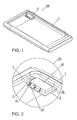
Fig. 1 is a perspective view showing aconnector fixing structure 100; -
Fig. 2 is an enlarged view, showing areceptacle connector 3 and its neighboring portion, ofFig. 1 ; -
Fig. 3 is a perspective view showing a housing 1; -
Fig. 4 is an enlarged view, showing a housing-sideinsertion opening member 5 and its neighboring portion, ofFig. 3 ; -
Fig. 5 is a front view of the housing-sideinsertion opening member 5; -
Fig. 6 is a perspective view of thereceptacle connector 3; -
Fig. 7 is an exploded view of thereceptacle connector 3, wherein the illustration of asubstrate 21 is omitted; -
Fig. 8 is a front view of thereceptacle connector 3, wherein the illustration of thesubstrate 21 is omitted; -
Fig. 9 is a plan view of thereceptacle connector 3, wherein the illustration of thesubstrate 21 is omitted; -
Fig. 10 is an A-A cross-sectional view ofFig. 8 ; -
Fig. 11 is a side view of thereceptacle connector 3, wherein the illustration of thesubstrate 21 is omitted; -
Fig. 12 is a B-B cross-sectional view ofFig. 8 ; -
Fig. 13 is a C-C cross-sectional view ofFig. 11 ; -
Fig. 14 is a cross-sectional view showing a state where thereceptacle connector 3 of theconnector fixing structure 100 and anaudio plug 210 are combined together, wherein the illustration of abody 11 of the housing 1 is omitted; -
Fig. 15 is a diagram showing a process of manufacturing theconnector fixing structure 100; -
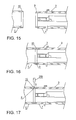
Fig. 16 is a diagram showing a process of manufacturing theconnector fixing structure 100; -
Fig. 17 is a diagram showing a process of manufacturing theconnector fixing structure 100; and -
Fig. 18 is a diagram showing a related art connector. - Hereinbelow, a preferred embodiment of this invention will be described in detail with reference to the drawings.
- First, referring to
Figs. 1 to 6 , aconnector fixing structure 100 according to this embodiment will be briefly described. - Herein, as the
connector fixing structure 100, there is shown by way of example a fixing structure where areceptacle connector 3 into which anaudio plug 210 as a mating connector is adapted to be inserted is fixed to a housing 1 of a smartphone. - As shown in
Figs. 1 and 2 , theconnector fixing structure 100 comprises the housing 1 and thereceptacle connector 3. - More specifically, as shown in
Figs. 3 to 5 , the housing 1 is integrally formed with a tubular resin housing-sideinsertion opening member 5 protruding inward and, as shown inFigs. 1 and 2 , thereceptacle connector 3 is provided in the housing 1 and joined to the housing-sideinsertion opening member 5. - As shown in
Fig. 6 , thereceptacle connector 3 has a connector-sideinsertion opening member 7 having a shape corresponding to that of the housing-sideinsertion opening member 5 and aresin welding portion 9 provided to the connector-sideinsertion opening member 7 and adapted to be combined with the housing-sideinsertion opening member 5. - Although details will be described later, in the
connector fixing structure 100, the connector-sideinsertion opening member 7 is welded to the housing-sideinsertion opening member 5 by melting thewelding portion 9 over its entire circumference (in this embodiment, surfaces of thewelding portion 9 and the housing-sideinsertion opening member 5 are melted together to be integrated with each other with no gap therebetween). - Next, the respective members forming the
connector fixing structure 100 will be described in more detail. - First, the structure of the housing 1 will be described with reference to
Figs. 3 to 5 . - As shown in
Fig. 3 , the housing 1 has a box-shaped body 11 and the box-shaped body 11 forms anopening portion 17 whose front surface is partially opened. - The
opening portion 17 is opened for incorporating non-illustrated electronic components forming the smartphone and thereceptacle connector 3 and is a portion where a display portion such as a liquid crystal display portion is fitted. - As shown in
Figs. 3 to 5 , thebody 11 is provided at a part of its upper surface with the tubular resin housing-sideinsertion opening member 5 protruding inward. - Herein, the term "tubular" represents not only a hollow circular cylindrical shape, but also a hollow rectangular parallelepiped shape.
- As shown in
Fig. 5 , the housing-sideinsertion opening member 5 has an oval (track-like) front shape and is formed at its center with a housing-side throughhole 13 having a shape corresponding to that of the later-describedaudio plug 210, i.e. having a round hole shape in this embodiment. Theaudio plug 210 is adapted to be inserted into the housing-side throughhole 13. - As shown in
Fig. 5 , the thickness of the housing-sideinsertion opening member 5 is set such that a thickness L2 in a height direction is smaller than a thickness L1 in a width direction. - By setting the thickness L1 in the width direction to be large, the strength of the housing-side
insertion opening member 5 can be ensured without setting the thickness L2 in the height direction to be large and therefore it is possible to achieve a reduction in height simultaneously with ensuring the strength. - The housing-side
insertion opening member 5 is not provided with a member, such as a cover, closing the housing-side throughhole 13 so that the housing-side throughhole 13 is opened through from the inside to the outside of the housing 1. - As shown in
Figs. 4 and 5 , the housing-sideinsertion opening member 5 has, at its end in a protruding direction toward the inside of the housing 1, a concave joiningportion 15 having an annular shape which is thinner than the other part of the housing-sideinsertion opening member 5. - Although details will be described later, the joining
portion 15 is a portion into which the welding portion 9 (connector-side insertion opening member 7) of thereceptacle connector 3 is inserted. - Next, the structure of the
receptacle connector 3 will be described with reference toFigs. 6 to 14 . - As shown in
Fig. 6 , thereceptacle connector 3 comprises asubstrate 21, a box-shapedinsulator 23 mounted on thesubstrate 21, and the connector-sideinsertion opening member 7 provided at one surface of theinsulator 23 and adapted to be joined to the housing-sideinsertion opening member 5 of the housing 1. - More specifically, as shown in
Fig. 7 , theinsulator 23 comprises abase insulator 25 forming a bottom portion of the box and acover insulator 29 combined with thebase insulator 25 and forming side portions and an upper portion of the box. - The
base insulator 25 is provided withcolumnar guide portions 31 which form a space into which theaudio plug 210 is adapted to be inserted (seeFig. 14 ). Behind theguide portions 31, there are provided a pair of plate-like locking portions 33 adapted to hold theaudio plug 210 by sandwiching it, acontact portion 35 serving as a stopper against which the tip of theaudio plug 210 is adapted to abut, and aspring 37 which urges thecontact portion 35 in a direction opposite to an insertion direction of theaudio plug 210. - As shown in
Figs. 7 to 13 , thecover insulator 29 is integrally formed with a plurality ofcontacts 34 so as to surround theguide portions 31. - Each
contact 34 is a member for establishing electrical connection between theaudio plug 210 and thereceptacle connector 3. As shown inFig. 13 , eachcontact 34 has one end which forms acontact portion 36 for contact with theaudio plug 210 and the other end which forms a mountingportion 43 exposed to the outside of thecover insulator 29 and adapted to be connected to a corresponding one ofcontacts 45 of thesubstrate 21 by soldering or the like. - On the other hand, as described before, the connector-side
insertion opening member 7 has a shape corresponding to that of the housing-sideinsertion opening member 5. - Specifically, as shown in
Fig. 8 , the connector-sideinsertion opening member 7 has an oval (track-like) front shape and is formed at its center with a connector-side throughhole 39 having a shape corresponding to that of theaudio plug 210, i.e. having a round hole shape in this embodiment. Theaudio plug 210 is adapted to be inserted into the connector-side throughhole 39. - As shown in
Fig. 8 , the thickness of the connector-sideinsertion opening member 7 is set such that a thickness L4 in a height direction is smaller than a thickness L3 in a width direction. - By setting the thickness L3 in the width direction to be large, the strength of the connector-side
insertion opening member 7 can be ensured without setting the thickness L4 in the height direction to be large and therefore it is possible to achieve a reduction in height simultaneously with ensuring the strength. - On the other hand, an end portion of the connector-side
insertion opening member 7 has a shape corresponding to that of the joiningportion 15 of the housing-sideinsertion opening member 5 and forms thewelding portion 9. Specifically, as shown inFigs. 11 and 12 , thewelding portion 9 has a convex (boss-like) shape which is thinner than the other part of the connector-sideinsertion opening member 7 by the thickness of the joiningportion 15, and is inserted into the joiningportion 15 of the housing-sideinsertion opening member 5. - Further, the
welding portion 9 is welded to the joiningportion 15 over its entire circumference, thereby forming a waterproof structure. - A welding method is not particularly limited as long as it is a method that can melt the
welding portion 9. As a specific welding method, use may be made of, for example, laser welding or ultrasonic welding, but not necessarily limited thereto. - The type of laser is also not particularly limited and use may be made of a YAG (Yttrium Aluminum Garnet) laser, a laser diode, or the like.
- When carrying out laser welding, it is necessary that the housing 1 be made of a resin that transmits heating laser light and that at least the
welding portion 9 of thereceptacle connector 3 be made of a resin that absorbs the heating laser light. - As the resin that transmits the heating laser light, there can be cited by way of example an amorphous resin or a crystalline resin, but not necessarily limited thereto. In the case where the resin that transmits the heating laser light is colored, if the coloring is carried out using a dye coloring material, the heating laser light can be transmitted even in a colored state.
- On the other hand, as the resin that absorbs the heating laser light, there can be cited by way of example a resin using a coloring matter (black or the like) excellent in laser absorbency. A coloring material is preferably a combination of a pigment absorbing coloring matter and a dye absorbing coloring matter.
- As described above, in the
connector fixing structure 100, since the housing 1 and thereceptacle connector 3 are joined together by welding to form the waterproof structure, no seal member is required. - Consequently, the
connector fixing structure 100 can form the waterproof structure with the simple structure with no seal member and thus it becomes easy to reduce the size and thickness of theconnector fixing structure 100. - Further, since the housing 1 and the
receptacle connector 3 can be assembled together only by inserting thewelding portion 9 into the joiningportion 15 and welding them together, components and man-hours for holding the seal member are not required compared to the case where the seal member is used. - Accordingly, it is possible to simplify the assembly sequence and to reduce the manufacturing cost.
- Further, since the
connector fixing structure 100 can be assembled only by welding thewelding portion 9 to the joiningportion 15, the waterproof structure can be formed without mechanically deforming the housing-sideinsertion opening member 5. - Consequently, the restriction to the shape and position of the housing-side
insertion opening member 5 is small and thus the degree of design freedom is large compared to the case where the seal member is provided. - As described before, the
audio plug 210 is adapted to be inserted as a mating connector into theconnector fixing structure 100. Accordingly, the insertion sequence of theaudio plug 210 will be briefly described with reference toFig. 14 . - First, a pin-shaped
terminal 211 of theaudio plug 210 is inserted through the housing-side throughhole 13 of the housing-sideinsertion opening member 5 and through the connector-side throughhole 39 of the connector-sideinsertion opening member 7 so that atip portion 213 of the terminal 211 is brought into abutment with thecontact portion 35. - When the terminal 211 is further inserted against a repulsive force of the
spring 37, thetip portion 213 is sandwiched between the lockingportions 33 so that theaudio plug 210 is fixed. - In this state, the
contacts 34 are in contact with a peripheral surface of the terminal 211 so that theaudio plug 210 and thecontacts 34 are electrically connected together. - The foregoing is the insertion sequence of the
audio plug 210. - Next, a method of manufacturing the
connector fixing structure 100 will be briefly described with reference toFigs. 3 ,6 ,7 , and15 to 17 . - First, the housing 1 shown in
Fig. 3 and thereceptacle connector 3 shown inFig. 6 are prepared. - The
receptacle connector 3 is assembled, for example, in the following sequence. - First, the
contact portion 35 with thespring 37 incorporated therein is attached to thebase insulator 25 and, further, the lockingportions 33 are attached to thebase insulator 25. - Then, as shown in
Fig. 7 , the connector-sideinsertion opening member 7 is joined to thebase insulator 25. - A joining method between the
base insulator 25 and the connector-sideinsertion opening member 7 is, for example, welding, but not necessarily limited thereto. - Then, as shown in
Fig. 7 , thecover insulator 29 and thecontacts 34 are integrally formed together. Then, thebase insulator 25 and thecover insulator 29 are combined together, thereby forming theinsulator 23. - Finally, as shown in
Fig. 6 , the mountingportions 43 of thecontacts 34 are connected to thecontacts 45 of thesubstrate 21 by soldering or the like, thereby completing thereceptacle connector 3. - Then, the
receptacle connector 3 and the housing 1 are combined together. - Specifically, first, as shown in
Fig. 15 , thewelding portion 9 of the connector-sideinsertion opening member 7 is aligned with the joiningportion 15 of the housing-sideinsertion opening member 5 and, as shown inFig. 16 , thewelding portion 9 is inserted into the joiningportion 15. - Then, as shown in
Fig. 17 , laser light (arrow D inFig. 17 ) is irradiated to thewelding portion 9 from the joiningportion 15 side using alaser 200. - In this event, as described before, while the joining
portion 15 of the housing-sideinsertion opening member 5 transmits the laser light, thewelding portion 9 of the connector-sideinsertion opening member 7 absorbs the laser light. Consequently, the irradiated laser light passes through the joiningportion 15 to heat and melt thewelding portion 9. - The melted
welding portion 9 is welded to the joiningportion 15 so that the joiningportion 15 and thewelding portion 9 are joined together. - Further, by irradiating the laser light to the
welding portion 9 over its entire circumference, the entire periphery of thewelding portion 9 is welded to the joiningportion 15 so that the joiningportion 15 and thewelding portion 9 form a waterproof structure. - Since the housing-side
insertion opening member 5 is not deformed during the welding, the shape of the housing-side throughhole 13 is also not deformed. - Therefore, the joining
portion 15 and thewelding portion 9 are joined together without deformation or closing of the housing-side throughhole 13. - The foregoing is the method of manufacturing the
connector fixing structure 100. - As described above, according to this embodiment, the
connector fixing structure 100 comprises the housing 1 integrally formed with the tubular resin housing-sideinsertion opening member 5 protruding inward and thereceptacle connector 3 provided in the housing 1 and joined to the housing-sideinsertion opening member 5, wherein thereceptacle connector 3 has the connector-sideinsertion opening member 7 having the shape corresponding to that of the housing-sideinsertion opening member 5 and theresin welding portion 9 provided to the connector-sideinsertion opening member 7 and combined with the housing-sideinsertion opening member 5 and wherein the housing-sideinsertion opening member 5 and the connector-sideinsertion opening member 7 are welded together by melting thewelding portion 9 over its entire circumference. - Therefore, the
connector fixing structure 100 requires no seal member and thus can form the waterproof structure with the simple structure. - Further, since the housing 1 and the
receptacle connector 3 can be assembled together only by inserting thewelding portion 9 into the joiningportion 15 and welding them together, components and man-hours for holding the seal member are not required compared to the case where the seal member is used. - Accordingly, it is possible to simplify the assembly sequence and to reduce the manufacturing cost.
- Further, since the
connector fixing structure 100 can be assembled only by welding thewelding portion 9 to the joiningportion 15, the waterproof structure can be formed without mechanically deforming the housing-sideinsertion opening member 5. - Consequently, the restriction to the shape and position of the housing-side
insertion opening member 5 is small and thus the degree of design freedom is large compared to the case where the seal member is provided. - Further, the thickness L1 in the width direction is set to be greater than the thickness L2 in the height direction in the housing-side
insertion opening member 5, thereby ensuring the strength of the housing-sideinsertion opening member 5 by its thickness in the width direction. Likewise, the thickness L3 in the width direction is set to be greater than the thickness L4 in the height direction in the connector-sideinsertion opening member 7, thereby ensuring the strength of the connector-sideinsertion opening member 7 by its thickness in the width direction. - Consequently, it is possible to easily achieve a reduction in the height of the housing-side
insertion opening member 5 and the connector-sideinsertion opening member 7. - While the preferred embodiment of this invention has been described with reference to the accompanying drawings, this invention is not limited thereto. It is apparent that those skilled in the art can think of various changes and modifications in the category described in claims and it is understood that those also naturally belong to the technical scope of this invention.
- For example, while the housing-side
insertion opening member 5 and the connector-sideinsertion opening member 7 each have the oval front shape in the above-mentioned embodiment, it may have a rectangular front shape. - Further, while, as the housing, the housing 1 of the smartphone is shown by way of example in the above-mentioned embodiment, the housing is not limited to the smartphone housing.
- Further, while, as the connector, the
receptacle connector 3 into which theaudio plug 210 is adapted to be inserted is shown by way of example in the above-mentioned embodiment, the connector is not limited to that for theaudio plug 210 and also not limited to the receptacle connector.
Claims (12)
- A connector fixing structure comprising:a housing integrally formed with a tubular resin housing-side insertion opening member protruding inward; anda connector provided in the housing and joined to the housing-side insertion opening member,wherein the connector comprises:a connector-side insertion opening member having a shape corresponding to that of the housing-side insertion opening member; anda resin welding portion provided to the connector-side insertion opening member and combined with the housing-side insertion opening member, andwherein the housing-side insertion opening member and the connector-side insertion opening member are welded together by melting the welding portion over its entire circumference.
- The connector fixing structure according to claim 1, wherein the housing-side insertion opening member has a housing-side through hole which is opened through to the outside of the housing and into which a mating connector is adapted to be inserted.
- The connector fixing structure according to claim 1 or 2,
wherein the welding portion is heated and melted by irradiation of heating laser light,
wherein the housing is made of a resin that transmits the heating laser light, and
wherein at least the welding portion of the connector is made of a resin that absorbs the heating laser light. - The connector fixing structure according to claim 2 or 3, wherein the housing-side insertion opening member is such that its thickness in a height direction is smaller than its thickness in a width direction.
- The connector fixing structure according to claim 4, wherein the housing-side through hole has a circular front shape and the housing-side insertion opening member has an oval front shape.
- The connector fixing structure according to any one of claims 1 to 5, wherein the connector-side insertion opening member is such that its thickness in a height direction is smaller than its thickness in a width direction.
- The connector fixing structure according to claim 6,
wherein the connector-side insertion opening member has a connector-side through hole into which the mating connector is adapted to be inserted, and
wherein the connector-side through hole a circular front shape and the connector-side insertion opening member has an oval front shape. - The connector fixing structure according to any one of claims 1 to 7,
wherein the housing-side insertion opening member has at its end a joining portion having a concave shape, and
wherein the welding portion has a convex shape corresponding to the concave shape of the joining portion. - A method of manufacturing a connector fixing structure, comprising the steps of:(a) preparing a housing integrally formed with a tubular resin housing-side insertion opening member protruding inward and a connector adapted to be provided in the housing and to be joined to the housing-side insertion opening member;(b) combining together the housing-side insertion opening member and a connector-side insertion opening member provided to the connector and having a shape corresponding to that of the housing-side insertion opening member; and(c) welding together the housing-side insertion opening member and the connector-side insertion opening member by melting a welding portion of the connector-side insertion opening member over its entire circumference.
- The method according to claim 9, wherein the step (c) welds together the housing-side insertion opening member and the connector-side insertion opening member so that a housing-side through hole of the housing-side insertion opening member is opened through to the outside of the housing.
- The method according to claim 9 or 10,
wherein the step (a) prepares the housing which is made of a resin that transmits heating laser light, and the connector at least the welding portion of which is made of a resin that absorbs the heating laser light, and
wherein the step (c) welds together the housing-side insertion opening member and the connector-side insertion opening member by irradiating the heating laser light to melt the welding portion of the connector-side insertion opening member over its entire circumference. - The method according to claim 11,
wherein the step (a) prepares the housing in which the housing-side insertion opening member has at its end a joining portion having a concave shape, and the connector in which the welding portion has a convex shape corresponding to the concave shape of the joining portion,
wherein the step (b) inserts the welding portion having the convex shape into the joining portion having the concave shape, and
wherein the step (c) irradiates the heating laser light to the welding portion from the joining portion side.
Applications Claiming Priority (1)
| Application Number | Priority Date | Filing Date | Title |
|---|---|---|---|
| JP2013153639A JP6084129B2 (en) | 2013-07-24 | 2013-07-24 | Connector fixing structure and manufacturing method of connector fixing structure |
Publications (2)
| Publication Number | Publication Date |
|---|---|
| EP2830167A1 true EP2830167A1 (en) | 2015-01-28 |
| EP2830167B1 EP2830167B1 (en) | 2015-10-07 |
Family
ID=51032903
Family Applications (1)
| Application Number | Title | Priority Date | Filing Date |
|---|---|---|---|
| EP14170694.5A Not-in-force EP2830167B1 (en) | 2013-07-24 | 2014-05-30 | Connector fixing structure and method of manufacturing the same |
Country Status (4)
| Country | Link |
|---|---|
| US (1) | US9254610B2 (en) |
| EP (1) | EP2830167B1 (en) |
| JP (1) | JP6084129B2 (en) |
| CN (1) | CN104348018B (en) |
Cited By (1)
| Publication number | Priority date | Publication date | Assignee | Title |
|---|---|---|---|---|
| WO2021144185A1 (en) * | 2020-01-17 | 2021-07-22 | Phoenix Contact Gmbh & Co. Kg | Method for forming a plastics component for an electrical conductor connection terminal system, and plastics component produced using the method |
Families Citing this family (5)
| Publication number | Priority date | Publication date | Assignee | Title |
|---|---|---|---|---|
| US20160346992A1 (en) * | 2015-05-28 | 2016-12-01 | Jabil Circuit, Inc. | System, apparatus and method for post-molding insertion of electrical contacts |
| US9729740B2 (en) * | 2015-09-21 | 2017-08-08 | Toshiba Tec Kabushiki Kaisha | Image display device |
| US9742113B1 (en) * | 2017-01-06 | 2017-08-22 | Harris Corporation | Electrical interface |
| CN109130218B (en) * | 2018-09-12 | 2024-01-05 | 富加宜连接器(东莞)有限公司 | Step-by-step press-in jig for bending terminal |
| KR102859999B1 (en) * | 2021-02-04 | 2025-09-16 | 삼성전자주식회사 | Mount-type earjack and electronic device with the same |
Citations (4)
| Publication number | Priority date | Publication date | Assignee | Title |
|---|---|---|---|---|
| US5041019A (en) * | 1990-11-01 | 1991-08-20 | Explosive Fabricators, Inc. | Transition joint for microwave package |
| EP2226185A1 (en) * | 2007-11-29 | 2010-09-08 | NGK Spark Plug Co., Ltd. | Metal-resin compound member |
| US20110056731A1 (en) * | 2009-09-09 | 2011-03-10 | Emerson Electric Co. | Solid core glass bead seal with stiffening rib |
| JP5155492B2 (en) | 2010-03-03 | 2013-03-06 | 株式会社エクセル電子 | Electronic equipment connection device and connection device |
Family Cites Families (6)
| Publication number | Priority date | Publication date | Assignee | Title |
|---|---|---|---|---|
| JPS52150792U (en) * | 1976-05-12 | 1977-11-15 | ||
| JP3180031B2 (en) * | 1996-06-28 | 2001-06-25 | 日立ソフトウエアエンジニアリング株式会社 | Fluorescence emission measurement device |
| JP2008288116A (en) * | 2007-05-21 | 2008-11-27 | Jst Mfg Co Ltd | Connector, method for manufacturing the same, and connection device |
| US8215018B2 (en) * | 2009-04-08 | 2012-07-10 | Canon Kabushiki Kaisha | Method for manufacturing liquid discharge head |
| JP5689000B2 (en) * | 2011-03-16 | 2015-03-25 | 株式会社エクセル電子 | Electronic device connector, electronic device plug and electronic device waterproof structure |
| JP5523484B2 (en) * | 2012-01-11 | 2014-06-18 | パナソニック株式会社 | Mobile device |
-
2013
- 2013-07-24 JP JP2013153639A patent/JP6084129B2/en not_active Expired - Fee Related
-
2014
- 2014-05-27 US US14/287,481 patent/US9254610B2/en not_active Expired - Fee Related
- 2014-05-30 EP EP14170694.5A patent/EP2830167B1/en not_active Not-in-force
- 2014-06-18 CN CN201410273229.2A patent/CN104348018B/en not_active Expired - Fee Related
Patent Citations (4)
| Publication number | Priority date | Publication date | Assignee | Title |
|---|---|---|---|---|
| US5041019A (en) * | 1990-11-01 | 1991-08-20 | Explosive Fabricators, Inc. | Transition joint for microwave package |
| EP2226185A1 (en) * | 2007-11-29 | 2010-09-08 | NGK Spark Plug Co., Ltd. | Metal-resin compound member |
| US20110056731A1 (en) * | 2009-09-09 | 2011-03-10 | Emerson Electric Co. | Solid core glass bead seal with stiffening rib |
| JP5155492B2 (en) | 2010-03-03 | 2013-03-06 | 株式会社エクセル電子 | Electronic equipment connection device and connection device |
Cited By (1)
| Publication number | Priority date | Publication date | Assignee | Title |
|---|---|---|---|---|
| WO2021144185A1 (en) * | 2020-01-17 | 2021-07-22 | Phoenix Contact Gmbh & Co. Kg | Method for forming a plastics component for an electrical conductor connection terminal system, and plastics component produced using the method |
Also Published As
| Publication number | Publication date |
|---|---|
| EP2830167B1 (en) | 2015-10-07 |
| CN104348018A (en) | 2015-02-11 |
| JP2015026443A (en) | 2015-02-05 |
| CN104348018B (en) | 2017-04-12 |
| US20150031243A1 (en) | 2015-01-29 |
| JP6084129B2 (en) | 2017-02-22 |
| US9254610B2 (en) | 2016-02-09 |
Similar Documents
| Publication | Publication Date | Title |
|---|---|---|
| EP2830167B1 (en) | Connector fixing structure and method of manufacturing the same | |
| JP5306746B2 (en) | Battery pack | |
| US20180316104A1 (en) | Bus bar and method of manufacturing bus bar | |
| EP2869357A1 (en) | Square battery and square battery manufacturing method | |
| JP6024092B2 (en) | Metal container manufacturing method, metal container, power storage element, and power storage module | |
| JP6265852B2 (en) | connector | |
| US20200053258A1 (en) | Camera module and camera module manufacturing method | |
| JP6282794B2 (en) | Storage element and method for manufacturing the same | |
| KR20150052755A (en) | A battery cell connecting board | |
| JP2022510118A (en) | Receptacle connector | |
| KR101927927B1 (en) | Receptacle connetor for improving shielding performance | |
| JP2013186949A (en) | Connection structure, and method of manufacturing the same | |
| KR20170131899A (en) | Busbar assembly | |
| JP2019053943A (en) | Module connector | |
| KR102490863B1 (en) | Manufacturing method for secondary battery | |
| JP2008288116A (en) | Connector, method for manufacturing the same, and connection device | |
| JP6743270B2 (en) | Method and component composite for forming a laser welded joint | |
| JP2012004207A (en) | Terminal box for solar cell module | |
| JP2013008645A (en) | Terminal fitting | |
| TW202505819A (en) | Car camera rear housing and car camera housing | |
| JP2010118525A (en) | Terminal box for solar cell module | |
| JP2020187895A (en) | Pressure welding terminal, terminal-equipped wire, and connector | |
| JP4030121B2 (en) | connector | |
| JP2013016346A (en) | Connection structure of bus bar and lead wire | |
| JP2014191988A (en) | Terminal module |
Legal Events
| Date | Code | Title | Description |
|---|---|---|---|
| 17P | Request for examination filed |
Effective date: 20140530 |
|
| AK | Designated contracting states |
Kind code of ref document: A1 Designated state(s): AL AT BE BG CH CY CZ DE DK EE ES FI FR GB GR HR HU IE IS IT LI LT LU LV MC MK MT NL NO PL PT RO RS SE SI SK SM TR |
|
| AX | Request for extension of the european patent |
Extension state: BA ME |
|
| PUAI | Public reference made under article 153(3) epc to a published international application that has entered the european phase |
Free format text: ORIGINAL CODE: 0009012 |
|
| RBV | Designated contracting states (corrected) |
Designated state(s): AL AT BE BG CH CY CZ DE DK EE ES FI FR GB GR HR HU IE IS IT LI LT LU LV MC MK MT NL NO PL PT RO RS SE SI SK SM TR |
|
| GRAP | Despatch of communication of intention to grant a patent |
Free format text: ORIGINAL CODE: EPIDOSNIGR1 |
|
| INTG | Intention to grant announced |
Effective date: 20150422 |
|
| GRAS | Grant fee paid |
Free format text: ORIGINAL CODE: EPIDOSNIGR3 |
|
| GRAA | (expected) grant |
Free format text: ORIGINAL CODE: 0009210 |
|
| AK | Designated contracting states |
Kind code of ref document: B1 Designated state(s): AL AT BE BG CH CY CZ DE DK EE ES FI FR GB GR HR HU IE IS IT LI LT LU LV MC MK MT NL NO PL PT RO RS SE SI SK SM TR |
|
| REG | Reference to a national code |
Ref country code: GB Ref legal event code: FG4D |
|
| REG | Reference to a national code |
Ref country code: AT Ref legal event code: REF Ref document number: 754246 Country of ref document: AT Kind code of ref document: T Effective date: 20151015 Ref country code: CH Ref legal event code: EP |
|
| REG | Reference to a national code |
Ref country code: IE Ref legal event code: FG4D |
|
| REG | Reference to a national code |
Ref country code: DE Ref legal event code: R096 Ref document number: 602014000306 Country of ref document: DE |
|
| REG | Reference to a national code |
Ref country code: NL Ref legal event code: MP Effective date: 20151007 |
|
| REG | Reference to a national code |
Ref country code: AT Ref legal event code: MK05 Ref document number: 754246 Country of ref document: AT Kind code of ref document: T Effective date: 20151007 |
|
| REG | Reference to a national code |
Ref country code: LT Ref legal event code: MG4D |
|
| PG25 | Lapsed in a contracting state [announced via postgrant information from national office to epo] |
Ref country code: ES Free format text: LAPSE BECAUSE OF FAILURE TO SUBMIT A TRANSLATION OF THE DESCRIPTION OR TO PAY THE FEE WITHIN THE PRESCRIBED TIME-LIMIT Effective date: 20151007 Ref country code: IT Free format text: LAPSE BECAUSE OF FAILURE TO SUBMIT A TRANSLATION OF THE DESCRIPTION OR TO PAY THE FEE WITHIN THE PRESCRIBED TIME-LIMIT Effective date: 20151007 Ref country code: NL Free format text: LAPSE BECAUSE OF FAILURE TO SUBMIT A TRANSLATION OF THE DESCRIPTION OR TO PAY THE FEE WITHIN THE PRESCRIBED TIME-LIMIT Effective date: 20151007 Ref country code: HR Free format text: LAPSE BECAUSE OF FAILURE TO SUBMIT A TRANSLATION OF THE DESCRIPTION OR TO PAY THE FEE WITHIN THE PRESCRIBED TIME-LIMIT Effective date: 20151007 Ref country code: LT Free format text: LAPSE BECAUSE OF FAILURE TO SUBMIT A TRANSLATION OF THE DESCRIPTION OR TO PAY THE FEE WITHIN THE PRESCRIBED TIME-LIMIT Effective date: 20151007 Ref country code: NO Free format text: LAPSE BECAUSE OF FAILURE TO SUBMIT A TRANSLATION OF THE DESCRIPTION OR TO PAY THE FEE WITHIN THE PRESCRIBED TIME-LIMIT Effective date: 20160107 Ref country code: IS Free format text: LAPSE BECAUSE OF FAILURE TO SUBMIT A TRANSLATION OF THE DESCRIPTION OR TO PAY THE FEE WITHIN THE PRESCRIBED TIME-LIMIT Effective date: 20160207 |
|
| PG25 | Lapsed in a contracting state [announced via postgrant information from national office to epo] |
Ref country code: LV Free format text: LAPSE BECAUSE OF FAILURE TO SUBMIT A TRANSLATION OF THE DESCRIPTION OR TO PAY THE FEE WITHIN THE PRESCRIBED TIME-LIMIT Effective date: 20151007 Ref country code: PT Free format text: LAPSE BECAUSE OF FAILURE TO SUBMIT A TRANSLATION OF THE DESCRIPTION OR TO PAY THE FEE WITHIN THE PRESCRIBED TIME-LIMIT Effective date: 20160208 Ref country code: SE Free format text: LAPSE BECAUSE OF FAILURE TO SUBMIT A TRANSLATION OF THE DESCRIPTION OR TO PAY THE FEE WITHIN THE PRESCRIBED TIME-LIMIT Effective date: 20151007 Ref country code: RS Free format text: LAPSE BECAUSE OF FAILURE TO SUBMIT A TRANSLATION OF THE DESCRIPTION OR TO PAY THE FEE WITHIN THE PRESCRIBED TIME-LIMIT Effective date: 20151007 Ref country code: PL Free format text: LAPSE BECAUSE OF FAILURE TO SUBMIT A TRANSLATION OF THE DESCRIPTION OR TO PAY THE FEE WITHIN THE PRESCRIBED TIME-LIMIT Effective date: 20151007 Ref country code: AT Free format text: LAPSE BECAUSE OF FAILURE TO SUBMIT A TRANSLATION OF THE DESCRIPTION OR TO PAY THE FEE WITHIN THE PRESCRIBED TIME-LIMIT Effective date: 20151007 Ref country code: GR Free format text: LAPSE BECAUSE OF FAILURE TO SUBMIT A TRANSLATION OF THE DESCRIPTION OR TO PAY THE FEE WITHIN THE PRESCRIBED TIME-LIMIT Effective date: 20160108 |
|
| REG | Reference to a national code |
Ref country code: DE Ref legal event code: R097 Ref document number: 602014000306 Country of ref document: DE |
|
| PG25 | Lapsed in a contracting state [announced via postgrant information from national office to epo] |
Ref country code: CZ Free format text: LAPSE BECAUSE OF FAILURE TO SUBMIT A TRANSLATION OF THE DESCRIPTION OR TO PAY THE FEE WITHIN THE PRESCRIBED TIME-LIMIT Effective date: 20151007 |
|
| PLBE | No opposition filed within time limit |
Free format text: ORIGINAL CODE: 0009261 |
|
| STAA | Information on the status of an ep patent application or granted ep patent |
Free format text: STATUS: NO OPPOSITION FILED WITHIN TIME LIMIT |
|
| PG25 | Lapsed in a contracting state [announced via postgrant information from national office to epo] |
Ref country code: SK Free format text: LAPSE BECAUSE OF FAILURE TO SUBMIT A TRANSLATION OF THE DESCRIPTION OR TO PAY THE FEE WITHIN THE PRESCRIBED TIME-LIMIT Effective date: 20151007 Ref country code: RO Free format text: LAPSE BECAUSE OF FAILURE TO SUBMIT A TRANSLATION OF THE DESCRIPTION OR TO PAY THE FEE WITHIN THE PRESCRIBED TIME-LIMIT Effective date: 20151007 Ref country code: SM Free format text: LAPSE BECAUSE OF FAILURE TO SUBMIT A TRANSLATION OF THE DESCRIPTION OR TO PAY THE FEE WITHIN THE PRESCRIBED TIME-LIMIT Effective date: 20151007 Ref country code: BE Free format text: LAPSE BECAUSE OF NON-PAYMENT OF DUE FEES Effective date: 20160531 Ref country code: EE Free format text: LAPSE BECAUSE OF FAILURE TO SUBMIT A TRANSLATION OF THE DESCRIPTION OR TO PAY THE FEE WITHIN THE PRESCRIBED TIME-LIMIT Effective date: 20151007 Ref country code: DK Free format text: LAPSE BECAUSE OF FAILURE TO SUBMIT A TRANSLATION OF THE DESCRIPTION OR TO PAY THE FEE WITHIN THE PRESCRIBED TIME-LIMIT Effective date: 20151007 |
|
| 26N | No opposition filed |
Effective date: 20160708 |
|
| PG25 | Lapsed in a contracting state [announced via postgrant information from national office to epo] |
Ref country code: SI Free format text: LAPSE BECAUSE OF FAILURE TO SUBMIT A TRANSLATION OF THE DESCRIPTION OR TO PAY THE FEE WITHIN THE PRESCRIBED TIME-LIMIT Effective date: 20151007 |
|
| REG | Reference to a national code |
Ref country code: DE Ref legal event code: R119 Ref document number: 602014000306 Country of ref document: DE |
|
| PG25 | Lapsed in a contracting state [announced via postgrant information from national office to epo] |
Ref country code: BE Free format text: LAPSE BECAUSE OF FAILURE TO SUBMIT A TRANSLATION OF THE DESCRIPTION OR TO PAY THE FEE WITHIN THE PRESCRIBED TIME-LIMIT Effective date: 20151007 Ref country code: LU Free format text: LAPSE BECAUSE OF FAILURE TO SUBMIT A TRANSLATION OF THE DESCRIPTION OR TO PAY THE FEE WITHIN THE PRESCRIBED TIME-LIMIT Effective date: 20160530 |
|
| REG | Reference to a national code |
Ref country code: IE Ref legal event code: MM4A |
|
| REG | Reference to a national code |
Ref country code: FR Ref legal event code: ST Effective date: 20170131 |
|
| PG25 | Lapsed in a contracting state [announced via postgrant information from national office to epo] |
Ref country code: FR Free format text: LAPSE BECAUSE OF NON-PAYMENT OF DUE FEES Effective date: 20160531 Ref country code: DE Free format text: LAPSE BECAUSE OF NON-PAYMENT OF DUE FEES Effective date: 20161201 |
|
| PG25 | Lapsed in a contracting state [announced via postgrant information from national office to epo] |
Ref country code: IE Free format text: LAPSE BECAUSE OF NON-PAYMENT OF DUE FEES Effective date: 20160530 |
|
| REG | Reference to a national code |
Ref country code: CH Ref legal event code: PL |
|
| PG25 | Lapsed in a contracting state [announced via postgrant information from national office to epo] |
Ref country code: LI Free format text: LAPSE BECAUSE OF NON-PAYMENT OF DUE FEES Effective date: 20170531 Ref country code: CH Free format text: LAPSE BECAUSE OF NON-PAYMENT OF DUE FEES Effective date: 20170531 |
|
| PG25 | Lapsed in a contracting state [announced via postgrant information from national office to epo] |
Ref country code: HU Free format text: LAPSE BECAUSE OF FAILURE TO SUBMIT A TRANSLATION OF THE DESCRIPTION OR TO PAY THE FEE WITHIN THE PRESCRIBED TIME-LIMIT; INVALID AB INITIO Effective date: 20140530 |
|
| PG25 | Lapsed in a contracting state [announced via postgrant information from national office to epo] |
Ref country code: MK Free format text: LAPSE BECAUSE OF FAILURE TO SUBMIT A TRANSLATION OF THE DESCRIPTION OR TO PAY THE FEE WITHIN THE PRESCRIBED TIME-LIMIT Effective date: 20151007 Ref country code: CY Free format text: LAPSE BECAUSE OF FAILURE TO SUBMIT A TRANSLATION OF THE DESCRIPTION OR TO PAY THE FEE WITHIN THE PRESCRIBED TIME-LIMIT Effective date: 20151007 Ref country code: MC Free format text: LAPSE BECAUSE OF FAILURE TO SUBMIT A TRANSLATION OF THE DESCRIPTION OR TO PAY THE FEE WITHIN THE PRESCRIBED TIME-LIMIT Effective date: 20151007 Ref country code: MT Free format text: LAPSE BECAUSE OF NON-PAYMENT OF DUE FEES Effective date: 20160531 |
|
| PG25 | Lapsed in a contracting state [announced via postgrant information from national office to epo] |
Ref country code: BG Free format text: LAPSE BECAUSE OF FAILURE TO SUBMIT A TRANSLATION OF THE DESCRIPTION OR TO PAY THE FEE WITHIN THE PRESCRIBED TIME-LIMIT Effective date: 20151007 |
|
| PG25 | Lapsed in a contracting state [announced via postgrant information from national office to epo] |
Ref country code: AL Free format text: LAPSE BECAUSE OF FAILURE TO SUBMIT A TRANSLATION OF THE DESCRIPTION OR TO PAY THE FEE WITHIN THE PRESCRIBED TIME-LIMIT Effective date: 20151007 Ref country code: TR Free format text: LAPSE BECAUSE OF FAILURE TO SUBMIT A TRANSLATION OF THE DESCRIPTION OR TO PAY THE FEE WITHIN THE PRESCRIBED TIME-LIMIT Effective date: 20151007 |
|
| GBPC | Gb: european patent ceased through non-payment of renewal fee |
Effective date: 20180530 |
|
| PG25 | Lapsed in a contracting state [announced via postgrant information from national office to epo] |
Ref country code: GB Free format text: LAPSE BECAUSE OF NON-PAYMENT OF DUE FEES Effective date: 20180530 |
|
| PGFP | Annual fee paid to national office [announced via postgrant information from national office to epo] |
Ref country code: FI Payment date: 20190509 Year of fee payment: 6 |
|
| REG | Reference to a national code |
Ref country code: FI Ref legal event code: MAE |
|
| PG25 | Lapsed in a contracting state [announced via postgrant information from national office to epo] |
Ref country code: FI Free format text: LAPSE BECAUSE OF NON-PAYMENT OF DUE FEES Effective date: 20200530 |