EP2829903A1 - Light sheet-based imaging device with extended depth of field - Google Patents
Light sheet-based imaging device with extended depth of field Download PDFInfo
- Publication number
- EP2829903A1 EP2829903A1 EP14177272.3A EP14177272A EP2829903A1 EP 2829903 A1 EP2829903 A1 EP 2829903A1 EP 14177272 A EP14177272 A EP 14177272A EP 2829903 A1 EP2829903 A1 EP 2829903A1
- Authority
- EP
- European Patent Office
- Prior art keywords
- light sheet
- wfe
- microscope according
- objective lens
- specimen
- Prior art date
- Legal status (The legal status is an assumption and is not a legal conclusion. Google has not performed a legal analysis and makes no representation as to the accuracy of the status listed.)
- Granted
Links
Images


Classifications
-
- G—PHYSICS
- G02—OPTICS
- G02B—OPTICAL ELEMENTS, SYSTEMS OR APPARATUS
- G02B21/00—Microscopes
- G02B21/06—Means for illuminating specimens
-
- G—PHYSICS
- G02—OPTICS
- G02B—OPTICAL ELEMENTS, SYSTEMS OR APPARATUS
- G02B21/00—Microscopes
- G02B21/0004—Microscopes specially adapted for specific applications
- G02B21/002—Scanning microscopes
- G02B21/0024—Confocal scanning microscopes (CSOMs) or confocal "macroscopes"; Accessories which are not restricted to use with CSOMs, e.g. sample holders
- G02B21/0052—Optical details of the image generation
- G02B21/0076—Optical details of the image generation arrangements using fluorescence or luminescence
-
- G—PHYSICS
- G02—OPTICS
- G02B—OPTICAL ELEMENTS, SYSTEMS OR APPARATUS
- G02B21/00—Microscopes
- G02B21/36—Microscopes arranged for photographic purposes or projection purposes or digital imaging or video purposes including associated control and data processing arrangements
- G02B21/365—Control or image processing arrangements for digital or video microscopes
- G02B21/367—Control or image processing arrangements for digital or video microscopes providing an output produced by processing a plurality of individual source images, e.g. image tiling, montage, composite images, depth sectioning, image comparison
-
- G—PHYSICS
- G02—OPTICS
- G02B—OPTICAL ELEMENTS, SYSTEMS OR APPARATUS
- G02B27/00—Optical systems or apparatus not provided for by any of the groups G02B1/00 - G02B26/00, G02B30/00
- G02B27/0075—Optical systems or apparatus not provided for by any of the groups G02B1/00 - G02B26/00, G02B30/00 with means for altering, e.g. increasing, the depth of field or depth of focus
Definitions
- the present invention relates to imaging devices such in which a specimen is illuminated by means of a light sheet and imaged with an objective whose depth of field has been extended by using a wavefront encoder element or system.
- LSM Light sheet microscopy
- an image detector such as a CCD, CMOS, sCMOS cameras or equivalent/similar
- Optical sections are obtained by moving the object, which can then be combined to obtain a 3D representation of the object.
- LSM has wide range of variants that have been developed in recent years, adopting names such that Selective Plane Illumination Microscopy (SPIM), ultramicroscopy, Digital Scanned Laser Light Sheet Fluorescence Microscopy (DSLM), Orthogonal Plane Fluorescence Optical Sectioning (OPFOS), Thin Laser light Sheet Microscopy (TLSM), Objective Coupled Planar Illumination (OCPI), among others.
- SPIM Selective Plane Illumination Microscopy
- DSLM Digital Scanned Laser Light Sheet Fluorescence Microscopy
- OFOS Orthogonal Plane Fluorescence Optical Sectioning
- TLSM Thin Laser light Sheet Microscopy
- OCPI Objective Coupled Planar Illumination
- the light of a source is adapted to generate a light sheet.
- the light sheet can be created by using a cylindrical lens as these optical elements focus the beam in a direction (z) perpendicular to the beam propagation (x). This results (for the purposes of this patent) in a light sheet in the x-y plane.
- Figure 1 shows a schematic of such a standard light-sheet microscopy system. Light sheet illumination is sent to the specimen. The specimen is usually rotated or translated across the light sheet. Detection of the generated signal is performed orthogonal to the light sheet.
- An alternative method consists in creating the light sheet dynamically using a beam with equal or similar width or section in the y and z directions and scanning the beam in the y direction, at high speed, to create the light sheet.
- the beam can have different transversal intensity profiles, for example Gaussian beam or Bessel beams. Other beam intensity profiles could also be used such as 2D or 3D patterns generated by interference of light.
- FIG. 2 shows a detailed schematic of such a standard light-sheet microscopy system.
- a light sheet generator, 1, projects the sheet of light on the specimen.
- the specimen is supported by a specimen holder, 2, which is normally contained into a physiological chamber, 3, and moved in the z direction, or rotated (not shown in the image for clarity) across the light sheet.
- the generated light is captured orthogonally to the light sheet by an objective lens, 4, that projects an image of the generated light from the illuminated part of the object onto a detection unit, 5.
- the detection units contains an image detector and may also include other elements, such as tube lenses, zoom systems, filters, etc,
- the captured images are then digitally processed by the digital processing unit, 6, to retrieve the information of the specimen.
- the light generated at the specimen is usually described by any of the following physical processes: reflected/refracted/scattered light, the generation of fluorescence by one photon or two-photon absorption, the generation of second and third harmonic light, among others.
- the generated signal is then detected in the z direction, which is perpendicular to the light sheet (i.e., perpendicular to both the x and y direction) to form an image in an image detector by means of a collection objective and an appropriate imaging system (see Fig. 2 ).
- the collection objective must be at a distance in the z direction equal to the objective focal distance, with a tolerance corresponding to the depth of field of the objective (in the order of a few microns) to obtain in this way a clear 2D image generated by the plane illuminated with the light sheet.
- the light sheet is projected into the specimen through a light sheet generator, 1.
- the objective lens, 2 is placed at a distance equal to its focal length from the position of the light sheet. This distance is kept fixed within the objective depth of field (DoF).
- DoF objective depth of field
- the objective lens forms a 2D image of the object that is being illuminated by the light sheet. In this case, the depth of field of the objective lens is determined by the used objective.
- the light sheet In order to obtain a 3D image, the light sheet needs to illuminate the different parts of the specimen. Since the distance between the light sheet and the objective must be kept equal to the focal distance, the most usual approach to obtain the set of 2D images consist in a displacement (see Fig- 4A) or rotation of the specimen ( Fig. 4B ). This will result in collection of 2D images which are computer combined to generate a 3D image.
- the light sheet can be scanned (displaced) in the z direction, but in this case, the collection objective must be also displaced in the z direction to maintain the distance with the light sheet constant (see Fig. 4C ).
- Wavefront encoding refers to the use of a phase modulating element or system in conjunction with deconvolution algorithm to extend the depth of field (EDoF) of a imaging system while efficiently keeping the light throughput of the system (see e.g. patents PCT/US1999/009546 , US6940649 B2 , US7583442 B2 ).
- the phase modulating element or system is a mask or a combination of optical elements which is placed at the exit pupil plane (or any of its conjugated planes) of the imaging lens (for example of an objective) or imaging system.
- the WFE element or system introduces an optical path difference that result in a phase modulation.
- any phase mask intended for the extension of the DoF can be generated as a linear combination of Legendre polynomials over a predefined pupil shape. Any equivalent representation using other bases (e.g. Zernike polynomials) can be transformed to the said formula by doing the appropriate linear transformation of change of basis.
- Cubic WFE element which is the most common implementation, has been shown to offer a good trade-off between DoF extension and sensitivity to noise in the post-processing step.
- phase x ⁇ y exp j ⁇ ⁇ ⁇ x 3 + y 3 , where ⁇ represents the strength of the mask.
- ⁇ represents the strength of the mask.
- the invariance of the PSF extends over larger volumes but the noise amplification in the post-processed images is also increased.
- the presence of spherical aberration is an important issue that can be mitigated by the use of wavefront encoding.
- phase x ⁇ y exp j ⁇ ⁇ ⁇ x 3 + y 3 + ⁇ ⁇ x 2 ⁇ y + y 2 ⁇ x
- ⁇ and ⁇ are optimized for the requirements of each particular experiment.
- P and ⁇ are the normalized pupil radius and the azimuthal angle, respectively.
- This expression resembles the trefoil components of the Zernike polynomials, allowing a straightforward synthesis of these masks in any wavefront-correction based modulator such as deformable mirrors and spatial light modulators.
- phase ⁇ exp j ⁇ ⁇ ⁇ ⁇ ⁇
- phase ⁇ exp - j 2 ⁇ ⁇ ⁇ ln ⁇ ⁇ + ⁇ 2
- the resulting recorded 3D image is processed to recover the final 3D image. This could be done by using appropriate deconvolution methods.
- Standard wide-field microscopes are only capable to correctly image objects located at the objective focal distance (see Fig. 5A ). Converting a standard wide-field microscope to a WFE system with an extended depth of field is straightforward.
- the WFE element is designed to produce a determined DoF and it is simply placed in the back pupil of the microscope objective. Once the WFE element is known, an appropriate digital inverse filter can be designed by measuring the PSF. The digital restoration is then performed by deconvolution. This result in a 2D image that is the projection within the extended DoF direction of the 3D imaged object (see Fig. 5B ).
- the present invention consists on the use of a Wavefront Encoding (WFE) element or WFE system that is placed at the exit pupil of the objective lens in the collection arm of a Light Sheet Microscope (LSM).
- WFE Wavefront Encoding
- LSM Light Sheet Microscope
- the problems described above in WFE techniques are not present in the invention, since the 3D reconstruction is possible, the lateral shift and change on magnification can be calibrated and corrected, the scanning amplitude can be adjusted to the DoF to avoid noise light generated outside the DoF and the PSF can be calibrated at every plane.
- a final advantage of the presented mixed approach is that WFE techniques mitigate the aberrations in the detection path.
- the invention relies on the use of WFE to extend the depth of field of the collection objective in light sheet microscopy (LSM).
- LSM light sheet microscopy
- a light sheet microscope is composed of a light source, generally a laser, a light sheet generator, a chamber with the specimen holder. Perpendicular to the direction of the plane of the light sheet there is the imaging system that includes a collection objective placed at a distance from the light sheet equal to the focal distance, and an image detector (such as a CCD, CMOS, sCMOS camera or equivalent/similar).
- a light source generally a laser
- a light sheet generator Perpendicular to the direction of the plane of the light sheet there is the imaging system that includes a collection objective placed at a distance from the light sheet equal to the focal distance, and an image detector (such as a CCD, CMOS, sCMOS camera or equivalent/similar).
- a WFE, 7, is placed in the exit pupil plane (or any of its conjugated planes) of the objective lens (see Fig. 6 ).
- the light sheet created by the light sheet generator is scanned in the z direction while the objective lens, 4, and the specimen are both kept static.
- a wavefront encoding (WFE) element/system, 7, at the exit pupil (or at any of its conjugated planes) of the objective lens, 4, its depth of field is increased.
- WFE wavefront encoding
- the WFE element is a single optical element whereas WFE system is a combination of optical elements. Both result in a phase modulation described by a linear combination of Legendre polynomials, a cubic function, generalised cubic function, detailed generalised cubic function, polynomial with rotation symmetry including axicons and logarithm axicons and all the wavefront phases as described in the background section or any equivalent that results in an extended DoF.
- the WFE element can work in transmission or reflection configurations and the required phase modulation can be introduced by refractive index changes, material thickness or variations in the surface profile. These are designed to be placed between the objective lens and the detection unit, normally at the exit pupil plane of the objective lens. Examples of these are phase masks, rigid shaped mirrors, deformable mirrors, liquid crystals spatial light modulators (SLM), diffractive optical elements, holographic elements, micro-mirrors, photorefractive elements, axicons.
- phase masks rigid shaped mirrors, deformable mirrors, liquid crystals spatial light modulators (SLM), diffractive optical elements, holographic elements, micro-mirrors, photorefractive elements, axicons.
- SLM spatial light modulators
- the WFE system can also work in transmission or reflection and the required phase modulation can be introduced by refractive index changes, material thickness, variations in the surface profile, and variations in the transmittance/absorbance. These are designed normally to be placed in a conjugated plane, normally using a 4f configuration, with the exit pupil plane of the objective lens. Examples of these are optical systems that incorporate refractive or diffractive lenses in combination with phase masks, rigid shaped mirrors, deformable mirrors, liquid crystals SLM, diffractive optical elements, holographic elements, micromirrors, photorefractive elements, axicons, amplitude masks, binary masks.
- the surface profile, transmission or refractive index can be changed actively to adapt the depth of field to any specific requirement. This can be done by the use of wavefront sensors (WS).
- the WS is previously calibrated and is used to measures the wavefront at the pupil or any conjugated plane of the imaging system. Through a feedback loop, the WS set the desired shape to the DM or SLM that produces the required phase modulation.
- Fig. 7 illustrates a generalised embodiment of the invention, which should not be interpreted as restricting the scope of the invention, but just as an example of how the invention can be embodied.
- a light sheet created by a light-sheet generator, 1, is projected into the specimen which is hold by a specimen holder, 2, and may be placed inside a proper chamber, 3, to ensure adequate conditions for preserving the specimen.
- a z-light sheet scanning unit, 8, is incorporated into the light sheet generator to axially (z-direction) displace the light sheet.
- the objective lens, 4, is kept fixed and its DoF is extended by the WFE element or system, 7, that is placed at the exit pupil plane or at any of its conjugated planes.
- a detection unit, 5 captures the images generated by the light sheet in a synchronised way, by means of a synchronisation unit, 9, as the light sheet is displaced in the z direction.
- a 3D image is then obtained by a digital processing unit, 6, after being properly decoded by an adequate deconvolution process.
- FIG 8 Shows a preferred embodiment of the invention based on a WFE system which should not be interpreted as restricting the scope of the invention, but just as an example of how the invention can be practically implemented.
- a light sheet, created by any method, placed within the EDoF, will be correctly imaged by the detection unit. This relaxes the distance requirement between light sheet and objective, resulting in a simpler alignment.
- the objective lens can be replaced and no critical refocusing is needed.
- a light sheet, created by any method, which is deformed by the changes of refractive index in the specimen can be correctly imaged by the detection unit as far as the light sheet falls within the extended DoF.
- the displacement in the position of the light sheet and in the focal length of the objective lens that are caused by changes in the refractive index of the specimen can be correctly imaged by the detection unit as the light sheet still falls within the extended DoF.
- a light sheet scanned in the z direction within the limits of the extended DoF will be correctly imaged by the detection unit for any position of the light sheet ( Fig. 6 ). Therefore 2D images at different z positions of the light sheet can be captured to reconstruct a 3D image without the need to move neither the specimen nor the collecting objective. In this way, the mechanical movement and pressure waves do not affect the specimen, and the specimen development and viability is not compromised.
- the method for scanning the light sheet in the z direction can be produced by any means, including mechanical mirrors, driven by stepper or galvanometer motors, AcoustoOptic Modulator (AOM), Digital Micromirror Devices (DMD/DLP), Grating Light Valves, Liquid Crystal Digital Light Deflectors, Inorganic Digital Light Deflectors, or poligonal rotating mirrors.
- AOM AcoustoOptic Modulator
- DMD/DLP Digital Micromirror Devices
- Grating Light Valves Liquid Crystal Digital Light Deflectors
- Inorganic Digital Light Deflectors or poligonal rotating mirrors.
- the speed of the 3D imaging is limited only by the speed given by the scanning system and the capture time of the detection unit.
- both, the lateral shift in the image of the specimen and the magnification caused by the WFE element can be characterized for any position of the light sheet in the z direction, and be corrected with post-processing imaging techniques.
- a method to correct both effects consists in using a specimen of micro beads for acquiring point spread functions (PSF) at different depths. These PSF are acquired with both standard light sheet system for reference, and with the EDOF light sheet system.
- PSF point spread functions
- a process of image registration is employed afterwards, obtaining the transformation operators for translation, rotation and deformation based on the spatial coordinates X, Y, Z from the same microbeads obtained from both optical systems. Then any 3D image from a specimen can be correctly reconstructed using the obtained transformation operators.
- the position of the light sheet and/or the amplitude of the scanning of the light sheet in the z direction can be adjusted to fall within the DoF. Therefore no region outside the extended DoF is illuminated and does not result in noise in the resulting 2D images.
- the PSF can be characterized for any position of the light sheet in the z direction, and therefore the invariant nature of the PSF in the z direction is no longer needed.
- the artifacts present in traditional extended DOF microscopes that rely on one single invariant PSF for digitally restoring the entire volume can be avoided.
- the present invention can exploit the advantages of having an extended DOF to combine LSM with other microscopy techniques, such as Stochastic optic reconstruction microscopy (STORM), Photoactivation light microscopy (PALM), Structured Illumination Microscopy (SIM), Raman microespectroscopy, Foster resonant energy transfer microscopy (FRET), Stimulated emission depletion microscopy (STED), Optical Projection Tomography (OPT), Ratiometric imaging, Polarization anisotropy, etc, but with the advantage that it is a Non-invasive (non-perturbing), fast and ultra stable technique capable to image large specimens and follow in vivo fast dynamics or fast single particle tracking.
- STORM Stochastic optic reconstruction microscopy
- PAM Photoactivation light microscopy
- SIM Structured Illumination Microscopy
- Raman microespectroscopy Raman microespectroscopy
- FRET Foster resonant energy transfer microscopy
- STED Stimulated emission depletion microscopy
Landscapes
- Physics & Mathematics (AREA)
- General Physics & Mathematics (AREA)
- Optics & Photonics (AREA)
- Chemical & Material Sciences (AREA)
- Analytical Chemistry (AREA)
- Engineering & Computer Science (AREA)
- Multimedia (AREA)
- Computer Vision & Pattern Recognition (AREA)
- Microscoopes, Condenser (AREA)
Abstract
Description
- The present invention relates to imaging devices such in which a specimen is illuminated by means of a light sheet and imaged with an objective whose depth of field has been extended by using a wavefront encoder element or system.
- Light sheet microscopy (LSM) is a technique in which an specimen under investigation is illuminated with a sheet of laser light such that the fluorescence emitted from the specimen is recorded in the orthogonal direction with an image detector (such as a CCD, CMOS, sCMOS cameras or equivalent/similar) (
Fig. 1 ). Optical sections are obtained by moving the object, which can then be combined to obtain a 3D representation of the object. - LSM has wide range of variants that have been developed in recent years, adopting names such that Selective Plane Illumination Microscopy (SPIM), ultramicroscopy, Digital Scanned Laser Light Sheet Fluorescence Microscopy (DSLM), Orthogonal Plane Fluorescence Optical Sectioning (OPFOS), Thin Laser light Sheet Microscopy (TLSM), Objective Coupled Planar Illumination (OCPI), among others. (See, e.g. , Siedentopf, H. & Zsigmondy, R., Ann. Phys. -Berlin 10 , 1 -39 (1902) ; Voie, A. H. , et al., J. Microsc. -Oxf. 1 70 , 229-236 (1993); Fuchs, E. , et al., Opt. Express 10 , 145- 1 54 (2002) ; Huisken, J., et al., Science 305, 1007- 1009 (2004) ; Holekamp, T. F. , et al., Neuron 57, 661 -672 (2008) ; Dodt, H. U. et ai, Nat. Methods A, 331 - 336 (2007) ; Huisken, J. & Stainier, D. Y. R. , Development s, 1963- 1 975 (2009); and Keller, P. J. & Stelzer, E. H. K., Curr. Opin. Neurobiol. 18, 624-632 (2008), and
patents US2012098949 A1 ,US 20070109633 A1 ,EP 2444833 A1 andEP 2494399 A2 , the disclosures of each of which are incorporated herein by reference). - In a typical realization of LSM, the light of a source, generally a laser, is adapted to generate a light sheet. The light sheet can be created by using a cylindrical lens as these optical elements focus the beam in a direction (z) perpendicular to the beam propagation (x). This results (for the purposes of this patent) in a light sheet in the x-y plane.
Figure 1 shows a schematic of such a standard light-sheet microscopy system. Light sheet illumination is sent to the specimen. The specimen is usually rotated or translated across the light sheet. Detection of the generated signal is performed orthogonal to the light sheet. - An alternative method consists in creating the light sheet dynamically using a beam with equal or similar width or section in the y and z directions and scanning the beam in the y direction, at high speed, to create the light sheet. In this last case, the beam can have different transversal intensity profiles, for example Gaussian beam or Bessel beams. Other beam intensity profiles could also be used such as 2D or 3D patterns generated by interference of light. Once the sheet of light is generated, it is used to illuminate the specimen to be imaged.
-
Figure 2 shows a detailed schematic of such a standard light-sheet microscopy system. A light sheet generator, 1, projects the sheet of light on the specimen. The specimen is supported by a specimen holder, 2, which is normally contained into a physiological chamber, 3, and moved in the z direction, or rotated (not shown in the image for clarity) across the light sheet. The generated light is captured orthogonally to the light sheet by an objective lens, 4, that projects an image of the generated light from the illuminated part of the object onto a detection unit, 5. The detection units contains an image detector and may also include other elements, such as tube lenses, zoom systems, filters, etc, The captured images are then digitally processed by the digital processing unit, 6, to retrieve the information of the specimen. The light generated at the specimen is usually described by any of the following physical processes: reflected/refracted/scattered light, the generation of fluorescence by one photon or two-photon absorption, the generation of second and third harmonic light, among others. The generated signal is then detected in the z direction, which is perpendicular to the light sheet (i.e., perpendicular to both the x and y direction) to form an image in an image detector by means of a collection objective and an appropriate imaging system (seeFig. 2 ). The key point in this arrangement is that the collection objective must be at a distance in the z direction equal to the objective focal distance, with a tolerance corresponding to the depth of field of the objective (in the order of a few microns) to obtain in this way a clear 2D image generated by the plane illuminated with the light sheet. As can be seen infigure 3 , in the standard LSM, the light sheet is projected into the specimen through a light sheet generator, 1. The objective lens, 2, is placed at a distance equal to its focal length from the position of the light sheet. This distance is kept fixed within the objective depth of field (DoF). The objective lens forms a 2D image of the object that is being illuminated by the light sheet. In this case, the depth of field of the objective lens is determined by the used objective. - In order to obtain a 3D image, the light sheet needs to illuminate the different parts of the specimen. Since the distance between the light sheet and the objective must be kept equal to the focal distance, the most usual approach to obtain the set of 2D images consist in a displacement (see Fig- 4A) or rotation of the specimen (
Fig. 4B ). This will result in collection of 2D images which are computer combined to generate a 3D image. Alternatively, the light sheet can be scanned (displaced) in the z direction, but in this case, the collection objective must be also displaced in the z direction to maintain the distance with the light sheet constant (seeFig. 4C ). - Since in all the realization of LSM the distance between the object and the light sheet is fixed and must remain constant, all the setups to date come with a number of problems:
- ■ The alignment is critical. The distance of the objective to the light-sheet must be set with a precision of microns within the DoF of the objective, and the light sheet must be at 90° from the optical axis of the collection objective.
- ■ A change of the collection objective requires realignment and adjustment of the distance between the object and the light sheet.
- ■ Changes in the internal refractive index of the specimen effectively change the focal distance of the objective and can induce deformations, curvature and other inhomogeneities of the light sheet. These may result in a loss of focal position and therefore in a blurred image.
- ■ To obtain a 3D image
- o The object needs to be moved (either in the z direction or rotated).
- o Both the light sheet and the collection objective must be scanned (displaced) in the z direction, always maintaining constant the distance with the light sheet.
- ■ All the above mentioned points prevent the technique to be used for fast 3D imaging of biological specimens. Moreover, for in-vivo imaging the movement can perturb the specimen behaviour and development, resulting in an invasive technique.
- Wavefront encoding (WFE) refers to the use of a phase modulating element or system in conjunction with deconvolution algorithm to extend the depth of field (EDoF) of a imaging system while efficiently keeping the light throughput of the system (see e.g. patents
PCT/US1999/009546 ,US6940649 B2 ,US7583442 B2 ). In general in WFE, the phase modulating element or system is a mask or a combination of optical elements which is placed at the exit pupil plane (or any of its conjugated planes) of the imaging lens (for example of an objective) or imaging system. The WFE element or system introduces an optical path difference that result in a phase modulation. Examples are in transmission by refractive index changes, thickness or variations in the transmittance/absorbance of the WFE element, in reflection by variations in the surface profile of the WFE element. Wavefront encoding phase elements can, in general, be described by the formula describing the spatial phase profile introduced by the WFE to the light passing through it:
- Where j is the imaginary unit, k,l are integers and 0 ≤ k,l < ∞. This formula can be interpreted as: any phase mask intended for the extension of the DoF can be generated as a linear combination of Legendre polynomials over a predefined pupil shape. Any equivalent representation using other bases (e.g. Zernike polynomials) can be transformed to the said formula by doing the appropriate linear transformation of change of basis. Cubic WFE element, which is the most common implementation, has been shown to offer a good trade-off between DoF extension and sensitivity to noise in the post-processing step. This family of masks can be described by:

where α represents the strength of the mask. For high values of α the invariance of the PSF extends over larger volumes but the noise amplification in the post-processed images is also increased. In microscopy applications the presence of spherical aberration is an important issue that can be mitigated by the use of wavefront encoding. For this, a generalized cubic PM of the form:
can be employed, where the values of α and β are optimized for the requirements of each particular experiment. When β = -3α the former equation can be written in polar form as:
Here P and θ are the normalized pupil radius and the azimuthal angle, respectively. This expression resembles the trefoil components of the Zernike polynomials, allowing a straightforward synthesis of these masks in any wavefront-correction based modulator such as deformable mirrors and spatial light modulators. - Another special family of WFE elements that can be implemented is based in a rotational symmetry given by:

- Where P are the normalized pupil radius and α is related with the angle of the cone that determines the amount of DoF extension. In the particular case of k=1 it refers to a conical lens or axicon that can be described as:
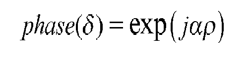
More flexibility to adjust the DoF can be obtained by changing the polynomial dependence of the phase profile to a logarithmic one, that can be expressed either as:
- Or

- Where α and β cam be varied to adjust the extension of the DoF. The former equation describes the backwards and the latter the forward version of the logarithmic axicon.
- The use of other phases with different shapes that are able to extend the DoF of an imaging system and that are not mentioned here can also be used.
- In all cases, the resulting recorded 3D image is processed to recover the final 3D image. This could be done by using appropriate deconvolution methods.
- Standard wide-field microscopes are only capable to correctly image objects located at the objective focal distance (see
Fig. 5A ). Converting a standard wide-field microscope to a WFE system with an extended depth of field is straightforward. The WFE element is designed to produce a determined DoF and it is simply placed in the back pupil of the microscope objective. Once the WFE element is known, an appropriate digital inverse filter can be designed by measuring the PSF. The digital restoration is then performed by deconvolution. This result in a 2D image that is the projection within the extended DoF direction of the 3D imaged object (seeFig. 5B ). - WFE used alone has however several problems when imaging a 3D object:
- ■ The 3D structure is encoded in the resulting 2D image but the 3D image cannot be recovered. This is incompatible with the concept of optical sectioning and results in a system incapable of depth discrimination.
- ■ WFE may introduce a lateral shift in the image of the specimen features at planes away from the best focus position. This introduces artifacts in the resulting image that cannot be identified nor corrected with image post-processing.
- ■ WFE causes a change of the magnification along the z axis (perspective projection), which introduces image artefacts and that cannot be identified, nor corrected with image post-processing.
- ■ The illuminated region of the specimen outside the designed extended DoF appears as a noise (a blurring) in the resulting 2D image.
- ■ To efficiently reconstruct the image, WFE algorithms require the point spread function (PSF) to be invariant along the DoF. This is not normally the case.
- The present invention consists on the use of a Wavefront Encoding (WFE) element or WFE system that is placed at the exit pupil of the objective lens in the collection arm of a Light Sheet Microscope (LSM). This WFE element or system is used to extend the depth of field of the imaging system in LSM.
- By combining LSM and WFE techniques it is possible to overcome several related problems as mentioned above. In brief, the use of WFE in the detection arm of the LSM results in an extended DoF which relaxes the restriction on the distance between the collecting objective and the light sheet. As a result, the alignment is non-critical, there is no need to carefully readjust the objective distance if replaced by another one, the changes in the focal distance of the objective and deformations of the light sheet caused by variations in the internal refractive index of the specimen are not critical, and finally, it allows for fast 3D imaging by only scanning the light sheet across the object without the need of moving neither the specimen nor the collection objective. In addition, thanks to the light sheet scanning, the problems described above in WFE techniques are not present in the invention, since the 3D reconstruction is possible, the lateral shift and change on magnification can be calibrated and corrected, the scanning amplitude can be adjusted to the DoF to avoid noise light generated outside the DoF and the PSF can be calibrated at every plane. A final advantage of the presented mixed approach is that WFE techniques mitigate the aberrations in the detection path.
- To complete the description and in order to provide for a better understanding of the invention, a set of drawings is provided. Said drawings illustrate a preferred embodiment of the invention, which should not be interpreted as restricting the scope of the invention, but just as an example of how the invention can be embodied.
-
Figure 1 shows a schematic of a standard light-sheet microscopy system. -
Figure 2 shows a detailed schematic of a standard light-sheet microscopy system. -
Figure 3 . depicts a standard LSM. -
Figure 4 shows how the specimen and/or objective lens has to be displaced in LSM -
Figure 5 shows the concept of wavefront encoding. -
Figure 6 is an schematic of the concept of WFE used in the invention. -
Figure 7 shows the basic scheme of the invention. -
Figure 8 is a particular embodiment of the invention. - The invention relies on the use of WFE to extend the depth of field of the collection objective in light sheet microscopy (LSM).
- A light sheet microscope is composed of a light source, generally a laser, a light sheet generator, a chamber with the specimen holder. Perpendicular to the direction of the plane of the light sheet there is the imaging system that includes a collection objective placed at a distance from the light sheet equal to the focal distance, and an image detector (such as a CCD, CMOS, sCMOS camera or equivalent/similar).
- According to the invention, a WFE, 7,is placed in the exit pupil plane (or any of its conjugated planes) of the objective lens (see
Fig. 6 ). The light sheet created by the light sheet generator is scanned in the z direction while the objective lens, 4, and the specimen are both kept static. By placing a wavefront encoding (WFE) element/system, 7, at the exit pupil (or at any of its conjugated planes) of the objective lens, 4, its depth of field is increased. By scanning the light sheet trough the specimen and within the extended DoF, 2D images for each z-position of the light sheet can be collected to create a 3D image. - The WFE element is a single optical element whereas WFE system is a combination of optical elements. Both result in a phase modulation described by a linear combination of Legendre polynomials, a cubic function, generalised cubic function, detailed generalised cubic function, polynomial with rotation symmetry including axicons and logarithm axicons and all the wavefront phases as described in the background section or any equivalent that results in an extended DoF.
- The WFE element can work in transmission or reflection configurations and the required phase modulation can be introduced by refractive index changes, material thickness or variations in the surface profile. These are designed to be placed between the objective lens and the detection unit, normally at the exit pupil plane of the objective lens. Examples of these are phase masks, rigid shaped mirrors, deformable mirrors, liquid crystals spatial light modulators (SLM), diffractive optical elements, holographic elements, micro-mirrors, photorefractive elements, axicons.
- The WFE system can also work in transmission or reflection and the required phase modulation can be introduced by refractive index changes, material thickness, variations in the surface profile, and variations in the transmittance/absorbance. These are designed normally to be placed in a conjugated plane, normally using a 4f configuration, with the exit pupil plane of the objective lens. Examples of these are optical systems that incorporate refractive or diffractive lenses in combination with phase masks, rigid shaped mirrors, deformable mirrors, liquid crystals SLM, diffractive optical elements, holographic elements, micromirrors, photorefractive elements, axicons, amplitude masks, binary masks.
- In the case of using deformable mirrors (DM) or spatial light modulators (SLM), the surface profile, transmission or refractive index can be changed actively to adapt the depth of field to any specific requirement. This can be done by the use of wavefront sensors (WS). The WS is previously calibrated and is used to measures the wavefront at the pupil or any conjugated plane of the imaging system. Through a feedback loop, the WS set the desired shape to the DM or SLM that produces the required phase modulation.
-
Fig. 7 illustrates a generalised embodiment of the invention, which should not be interpreted as restricting the scope of the invention, but just as an example of how the invention can be embodied. As shown inFigure 7 , a light sheet, created by a light-sheet generator, 1, is projected into the specimen which is hold by a specimen holder, 2, and may be placed inside a proper chamber, 3, to ensure adequate conditions for preserving the specimen. A z-light sheet scanning unit, 8, is incorporated into the light sheet generator to axially (z-direction) displace the light sheet. The objective lens, 4, is kept fixed and its DoF is extended by the WFE element or system, 7, that is placed at the exit pupil plane or at any of its conjugated planes. A detection unit, 5, captures the images generated by the light sheet in a synchronised way, by means of a synchronisation unit, 9, as the light sheet is displaced in the z direction. A 3D image is then obtained by a digital processing unit, 6, after being properly decoded by an adequate deconvolution process. -
Figure 8 . Shows a preferred embodiment of the invention based on a WFE system which should not be interpreted as restricting the scope of the invention, but just as an example of how the invention can be practically implemented. - - The light sheet generator consists of a cylindrical lens, 10, and an excitation lens, 11, separated by the sum of their focal distances. This produces a light sheet in the x, y, plane at the focal position of the excitation lens.
- - The z - Light-sheet Scanning Unit, 8, consists of a galvanometric mirror that scans the excitation beam in the z-direction. This is located at a distance equal to the focal length of the excitation lens.
- - The specimen, located at the specimen plane, is held by a specimen holder, 2, with six degrees of freedom, position (x, y, z) and angles (ø, θxz and θyz). The chamber, 3, contains the adequate conditions to allow proper optical excitation and collection of light while maintaining the proper conditions for the specimen (humidity, temperature, pH, osmotic pressure, etc).
- - The objective lens, 4, is placed at a distance equal to its focal length from the optical axis of the excitation arm.
- - A wavefront encoding system is placed in the detection arm. This is composed of relay system, consisting of a couple of relay lenses, 16 and 18, that conjugate the exit pupil of the objective lens, 12, to the surface of a deformable mirror, 19 (mirrors, 15 and 17 are used only for steering the beam). The deformable mirror is used to produce the appropriate phase modulation required for wavefront encoding, typically a cubic phase mask. This WFE system also incorporates a wavefront sensor, 23, to ensure the proper shape of the mirror according to the required phase modulation. Note that for convenience, we have incorporated a wavefront sensor which is only needed for calibration of the mirror. In our configuration, the wavefront sensor is placed at a conjugated plane of the surface of the mirror using a couple of relay lenses, 13 and 22.
Mirror 21 is only used to steer the light into the wavefront sensor and it has to be removed from the optical path once the correct phase is produced on the deformable mirror. - - The detection unit consists of a tube lens, 13, that is used to focus the collected light by the objective lens, 4, into the active area of the 2D image detector, 14 (
mirror 21 is removed from the optical path). Capturing of the images is made in a synchronised way with the displacement of the light sheet in z direction using a synchronisation unit, 9. - - The system can be used as a regular LSM by removing
mirrors - According to any of the embodiments described above, a light sheet, created by any method, placed within the EDoF, will be correctly imaged by the detection unit. This relaxes the distance requirement between light sheet and objective, resulting in a simpler alignment.
- According to any of the embodiments described above, once that the designed WFE element is placed in between the objective lens and the detection unit, the objective lens can be replaced and no critical refocusing is needed.
- According to any of the embodiments described above, a light sheet, created by any method, which is deformed by the changes of refractive index in the specimen can be correctly imaged by the detection unit as far as the light sheet falls within the extended DoF.
- According to any of the embodiments described above, the displacement in the position of the light sheet and in the focal length of the objective lens that are caused by changes in the refractive index of the specimen can be correctly imaged by the detection unit as the light sheet still falls within the extended DoF. This can be achieved as usually the extended DoF is on the orders of tens to hundreds of microns and the displacement of the focus is in the order of a few microns.
- According to any of the embodiments described above, a light sheet scanned in the z direction within the limits of the extended DoF will be correctly imaged by the detection unit for any position of the light sheet (
Fig. 6 ). Therefore 2D images at different z positions of the light sheet can be captured to reconstruct a 3D image without the need to move neither the specimen nor the collecting objective. In this way, the mechanical movement and pressure waves do not affect the specimen, and the specimen development and viability is not compromised. Here the method for scanning the light sheet in the z direction can be produced by any means, including mechanical mirrors, driven by stepper or galvanometer motors, AcoustoOptic Modulator (AOM), Digital Micromirror Devices (DMD/DLP), Grating Light Valves, Liquid Crystal Digital Light Deflectors, Inorganic Digital Light Deflectors, or poligonal rotating mirrors. In this case, the speed of the 3D imaging is limited only by the speed given by the scanning system and the capture time of the detection unit. - According to any of the embodiments described above, both, the lateral shift in the image of the specimen and the magnification caused by the WFE element can be characterized for any position of the light sheet in the z direction, and be corrected with post-processing imaging techniques. A method to correct both effects consists in using a specimen of micro beads for acquiring point spread functions (PSF) at different depths. These PSF are acquired with both standard light sheet system for reference, and with the EDOF light sheet system. A process of image registration is employed afterwards, obtaining the transformation operators for translation, rotation and deformation based on the spatial coordinates X, Y, Z from the same microbeads obtained from both optical systems. Then any 3D image from a specimen can be correctly reconstructed using the obtained transformation operators.
- According to any of the embodiments described above, the position of the light sheet and/or the amplitude of the scanning of the light sheet in the z direction can be adjusted to fall within the DoF. Therefore no region outside the extended DoF is illuminated and does not result in noise in the resulting 2D images.
- According to any of the embodiments described above, the PSF can be characterized for any position of the light sheet in the z direction, and therefore the invariant nature of the PSF in the z direction is no longer needed. As a consequence, the artifacts present in traditional extended DOF microscopes that rely on one single invariant PSF for digitally restoring the entire volume can be avoided.
- Similarly to the classical LSM, the present invention can exploit the advantages of having an extended DOF to combine LSM with other microscopy techniques, such as Stochastic optic reconstruction microscopy (STORM), Photoactivation light microscopy (PALM), Structured Illumination Microscopy (SIM), Raman microespectroscopy, Foster resonant energy transfer microscopy (FRET), Stimulated emission depletion microscopy (STED), Optical Projection Tomography (OPT), Ratiometric imaging, Polarization anisotropy, etc, but with the advantage that it is a Non-invasive (non-perturbing), fast and ultra stable technique capable to image large specimens and follow in vivo fast dynamics or fast single particle tracking.
- In this text, the term "comprises" and its derivations (such as "comprising", etc.) should not be understood in an excluding sense, that is, these terms should not be interpreted as excluding the possibility that what is described and defined may include further elements, steps, etc.
- On the other hand, the invention is obviously not limited to the specific embodiment(s) described herein, but also encompasses any variations that may be considered by any person skilled in the art (for example, as regards the choice of materials, dimensions, components, configuration, etc.), within the spirit of the invention.
Claims (11)
- Light sheet microscope for recording 3D images of a specimen, comprising a light sheet generator (1) and sheet scanning unit (8) that produces a light sheet (8a) that is scanned through the specimen, an objective lens (4) and an image detector (5) and characterized in that it further comprises a wavefront encoder element or system (7) positioned between the objective lens (4) and the image detector (5) at the exit pupil plane or a conjugated plane of the objective lens (4), for extending the depth of field of the objective lens (4).
- Light sheet microscope according to claim 1 wherein the wavefront enconder is a single optical element that is adapted to introduce an optical path difference that results in a phase modulation described by a linear combination of Legendre polynomials, a cubic profile or a polynomial with rotation symmetry.
- Light sheet microscope according to claim 2 where the WFE element can work in transmission or reflection configuration.
- Light sheet microscope according to claim 2 where the WFE element (7) is a phase mask.
- Light sheet microscope according to claim 2 where the WFE element (7) is an axicon.
- Light sheet microscope according to claim 1 where the wavefront encoder system is a combination of optical elements that is adapted to introduce an optical path difference that results in a phase modulation described by a linear combination of Legendre polynomials, a cubic profile or a polynomial with rotation symmetry
- Light sheet microscope according to claim 6 where the WFE system can work in transmission or reflection configuration.
- Light sheet microscope according to claim 6 wherein the wavefront encoding system (7) is composed of a deformable mirror (19) and a relay system, formed by a couple of relay lenses, (16, 18) that conjugate the exit pupil of the objective lens (12), to the surface of the deformable mirror (19) whose surface profile is modulated to result in an extended DoF.
- Light sheet microscope according to claim 8 wherein a wavefront sensor, (23) is placed at a conjugated plane of the mirror surface for measuring and controlling the phase modulation introduced by the deformable mirror.
- A light sheet microscope according to claims 2 and 6 where the WFE element or system is actively changed to adapt the depth of field to a specific requirement.
- A light sheet microscope according to claim 1 further comprising a digital processing unit (6) for decoding by an adequate deconvolution process the 2D images obtained by the image detector and transforming them into 3D images.
Applications Claiming Priority (1)
| Application Number | Priority Date | Filing Date | Title |
|---|---|---|---|
| US13/947,523 US9581798B2 (en) | 2013-07-22 | 2013-07-22 | Light sheet-based imaging device with extended depth of field |
Publications (2)
| Publication Number | Publication Date |
|---|---|
| EP2829903A1 true EP2829903A1 (en) | 2015-01-28 |
| EP2829903B1 EP2829903B1 (en) | 2021-09-15 |
Family
ID=51176982
Family Applications (1)
| Application Number | Title | Priority Date | Filing Date |
|---|---|---|---|
| EP14177272.3A Active EP2829903B1 (en) | 2013-07-22 | 2014-07-16 | Light sheet-based imaging device with extended depth of field |
Country Status (3)
| Country | Link |
|---|---|
| US (1) | US9581798B2 (en) |
| EP (1) | EP2829903B1 (en) |
| ES (1) | ES2900148T3 (en) |
Cited By (3)
| Publication number | Priority date | Publication date | Assignee | Title |
|---|---|---|---|---|
| WO2017167911A1 (en) * | 2016-03-30 | 2017-10-05 | Georg-August-Universität Göttingen Stiftung Öffentlichen Rechts, Universitätsmedizin | Method for generating a microscopic image |
| CN109477954A (en) * | 2016-05-30 | 2019-03-15 | 纽约市哥伦比亚大学理事会 | SCAPE microscopy and image reconstruction with phase modulating elements |
| WO2020126634A3 (en) * | 2018-12-21 | 2020-08-06 | Lavision Biotec Gmbh | Light sheet microscope with movable container |
Families Citing this family (29)
| Publication number | Priority date | Publication date | Assignee | Title |
|---|---|---|---|---|
| US20160041099A1 (en) * | 2014-08-06 | 2016-02-11 | University Of Oregon | Light sheet fluorescence and differential interference contrast microscope |
| WO2016049368A1 (en) * | 2014-09-24 | 2016-03-31 | The United States Of America, As Represented By Secretary, Department Of Health And Human Services | Resolution enhancement for light sheet microscopy systems and methods |
| DE102014119255A1 (en) * | 2014-12-19 | 2016-06-23 | Carl Zeiss Microscopy Gmbh | Method for light-sheet microscopic examination of a sample |
| JP6522361B2 (en) * | 2015-02-18 | 2019-05-29 | オリンパス株式会社 | Fluorescence microscope |
| CN104772908B (en) * | 2015-04-28 | 2024-05-03 | 深圳市宝迪斯科技有限公司 | SLA type three-dimensional printer |
| WO2016178856A1 (en) * | 2015-05-01 | 2016-11-10 | The Board Of Regents Of The University Of Texas System | Uniform and scalable light-sheets generated by extended focusing |
| WO2017075275A1 (en) * | 2015-10-29 | 2017-05-04 | The Board Of Trustees Of The Leland Stanford Junior University | Methods and systems for imaging a biological sample |
| DE102016204653B4 (en) * | 2016-03-21 | 2022-12-22 | Carl Zeiss Microscopy Gmbh | The invention relates to a light sheet microscope and a method for operating a light sheet microscope |
| US10876970B2 (en) | 2016-04-12 | 2020-12-29 | The Board Of Regents Of The University Of Texas System | Light-sheet microscope with parallelized 3D image acquisition |
| US20180192030A1 (en) * | 2016-06-07 | 2018-07-05 | Gary Greenberg | 4-D Video Of An Object Using A Microscope |
| EP3475753B1 (en) * | 2016-06-24 | 2025-04-09 | Howard Hughes Medical Institute | Automated adjustment of light sheet geometry in a microscope |
| WO2018033582A1 (en) * | 2016-08-15 | 2018-02-22 | Leica Microsystems Cms Gmbh | Light sheet microscope |
| DE102016117675B4 (en) * | 2016-09-20 | 2018-07-05 | Leica Microsystems Cms Gmbh | Microscope with a lighting module |
| EP4296654A3 (en) * | 2017-03-03 | 2024-02-28 | Pacific Biosciences of California, Inc. | High speed scanning system with acceleration tracking |
| CN111051954A (en) | 2017-07-20 | 2020-04-21 | 维微恩提斯显微镜有限责任公司 | Microscope, method of operating a microscope and method of imaging a sample |
| JP6932036B2 (en) * | 2017-07-31 | 2021-09-08 | シスメックス株式会社 | Cell imaging method, cell imaging device, particle imaging method and particle imaging device |
| EP3695263B1 (en) | 2017-10-12 | 2025-01-15 | Howard Hughes Medical Institute | High-resolution, real-time imaging with adaptive optics and lattice light sheets |
| CN109085137B (en) * | 2018-08-21 | 2020-08-28 | 中国科学院上海光学精密机械研究所 | Three-dimensional imaging device and imaging method based on K-space transformation |
| EP3903092A4 (en) * | 2018-12-26 | 2022-02-16 | The Regents of the University of California | SYSTEMS AND METHODS FOR TWO-DIMENSIONAL FLUORESCENCE WAVE PROPAGATION ON SURFACES USING DEPTH LEARNING |
| US20220299420A1 (en) * | 2019-08-30 | 2022-09-22 | The Regents Of The University Of California | Systems and methods for image cytometry |
| CA3153127A1 (en) | 2019-09-05 | 2021-03-11 | Apton Biosystems, Inc. | High speed scanning systems for super resolution imaging |
| US12141951B2 (en) * | 2019-10-15 | 2024-11-12 | Georg-August-Universität Göttingen Stiftung Öffentlichen Rechts Universitätsmedizin | Method and apparatus for contrast enhancement |
| EP4118416A4 (en) | 2020-03-13 | 2024-04-03 | The University Of Southern California | OPTIMIZED PHOTON COLLECTION FOR LIGHT-SHEET MICROSCOPY |
| CN111521608A (en) * | 2020-04-27 | 2020-08-11 | 中国科学院广州生物医药与健康研究院 | A super-resolution microscopic imaging method and microscope |
| US11915360B2 (en) | 2020-10-20 | 2024-02-27 | The Regents Of The University Of California | Volumetric microscopy methods and systems using recurrent neural networks |
| CN117043655A (en) | 2021-01-22 | 2023-11-10 | 维微恩提斯显微镜有限责任公司 | Microscope for imaging samples |
| CN114112874A (en) * | 2021-12-09 | 2022-03-01 | 中国科学技术大学 | Microscopic imaging system and imaging method for flow cytometer |
| WO2024129575A1 (en) * | 2022-12-12 | 2024-06-20 | Allen Institute | Selective-plane illumination microscopy with high étendue and long working distance objective lenses |
| EP4624135A1 (en) * | 2024-03-28 | 2025-10-01 | xolo GmbH | A light sheet forming arrangement |
Citations (7)
| Publication number | Priority date | Publication date | Assignee | Title |
|---|---|---|---|---|
| US6940649B2 (en) | 1995-02-03 | 2005-09-06 | The Regents Of The University Of Colorado | Wavefront coded imaging systems |
| US20070109633A1 (en) | 2002-12-09 | 2007-05-17 | Europaeisches Laboratorium Fuer Molekularbiologie (Embl) | Single plane illumination microscope |
| US7583442B2 (en) | 1995-02-03 | 2009-09-01 | Omnivision Cdm Optics, Inc. | Extended depth of field optical systems |
| WO2011059826A2 (en) * | 2009-10-29 | 2011-05-19 | California Institute Of Technology | Multiple-photon excitation light sheet illumination microscope |
| US20120049087A1 (en) * | 2010-08-25 | 2012-03-01 | California Institute Of Technology | Simultaneous orthogonal light sheet microscopy and computed optical tomography |
| EP2444833A1 (en) | 2010-10-22 | 2012-04-25 | Leica Microsystems CMS GmbH | SPIM microscope with sequential light sheet |
| US9909546B2 (en) | 2013-10-30 | 2018-03-06 | Man Diesel & Turbo, Filial Af Man Diesel & Turbo Se, Tyskland | Fuel valve for injecting gaseous fuel into a combustion chamber of a self-igniting internal combustion engine, engine, method and use |
Family Cites Families (6)
| Publication number | Priority date | Publication date | Assignee | Title |
|---|---|---|---|---|
| US3493290A (en) * | 1966-01-14 | 1970-02-03 | Mitre Corp | Three-dimensional display |
| WO2004077819A1 (en) * | 2003-02-25 | 2004-09-10 | Matsushita Electric Industrial Co., Ltd. | Optical sensor |
| US7180673B2 (en) * | 2003-03-28 | 2007-02-20 | Cdm Optics, Inc. | Mechanically-adjustable optical phase filters for modifying depth of field, aberration-tolerance, anti-aliasing in optical systems |
| US8369642B2 (en) * | 2006-11-21 | 2013-02-05 | Stmicroelectronics (Research & Development) Ltd | Artifact removal from phase encoded images |
| DE102007047461A1 (en) * | 2007-09-28 | 2009-04-02 | Carl Zeiss Microimaging Gmbh | Method and optical arrangement for examining a sample |
| DE102007063274B8 (en) * | 2007-12-20 | 2022-12-15 | Albert-Ludwigs-Universität Freiburg | microscope |
-
2013
- 2013-07-22 US US13/947,523 patent/US9581798B2/en active Active
-
2014
- 2014-07-16 ES ES14177272T patent/ES2900148T3/en active Active
- 2014-07-16 EP EP14177272.3A patent/EP2829903B1/en active Active
Patent Citations (9)
| Publication number | Priority date | Publication date | Assignee | Title |
|---|---|---|---|---|
| US6940649B2 (en) | 1995-02-03 | 2005-09-06 | The Regents Of The University Of Colorado | Wavefront coded imaging systems |
| US7583442B2 (en) | 1995-02-03 | 2009-09-01 | Omnivision Cdm Optics, Inc. | Extended depth of field optical systems |
| US20070109633A1 (en) | 2002-12-09 | 2007-05-17 | Europaeisches Laboratorium Fuer Molekularbiologie (Embl) | Single plane illumination microscope |
| WO2011059826A2 (en) * | 2009-10-29 | 2011-05-19 | California Institute Of Technology | Multiple-photon excitation light sheet illumination microscope |
| EP2494399A2 (en) | 2009-10-29 | 2012-09-05 | California Institute of Technology | Multiple-photon excitation light sheet illumination microscope |
| US20120049087A1 (en) * | 2010-08-25 | 2012-03-01 | California Institute Of Technology | Simultaneous orthogonal light sheet microscopy and computed optical tomography |
| EP2444833A1 (en) | 2010-10-22 | 2012-04-25 | Leica Microsystems CMS GmbH | SPIM microscope with sequential light sheet |
| US20120098949A1 (en) | 2010-10-22 | 2012-04-26 | Leica Microsystems Cms Gmbh | Spim microscope with a sted light sheet |
| US9909546B2 (en) | 2013-10-30 | 2018-03-06 | Man Diesel & Turbo, Filial Af Man Diesel & Turbo Se, Tyskland | Fuel valve for injecting gaseous fuel into a combustion chamber of a self-igniting internal combustion engine, engine, method and use |
Non-Patent Citations (10)
| Title |
|---|
| C. MAURER ET AL: "What spatial light modulators can do for optical microscopy", LASER & PHOTONICS REVIEWS, vol. 5, no. 1, 3 January 2011 (2011-01-03), pages 81 - 101, XP055059479, ISSN: 1863-8880, DOI: 10.1002/lpor.200900047 * |
| DODT, H. U., NAT. METHODS A, 2007, pages 331 - 336 |
| FUCHS, E. ET AL., OPT. EXPRESS, vol. 1 0, 2002, pages 145 - 1 54 |
| HOLEKAMP, T. F. ET AL., NEURON, vol. 57, 2008, pages 661 - 672 |
| HUISKEN ET AL., SCIENCE, vol. 305, 2004, pages 1007 - 1009 |
| HUISKEN, J.; STAINIER, D. Y. R., DEVELOPMENT S, 2009, pages 1963 - 1 975 |
| KELLER, P. J.; STELZER, E. H. K., CURR. OPIN. NEUROBIOL., vol. 18, 2008, pages 624 - 632 |
| SIEDENTOPF, H.; ZSIGMONDY, R., ANN. PHYS. -BERLIN, vol. 1 0, 1902, pages 1 - 39 |
| TUCKER S C ET AL: "Extended depth of field and aberration control for inexpensive digital microscope systems", OPTICS EXPRESS, OSA PUBLISHING, US, vol. 4, no. 11, 1 January 1999 (1999-01-01), pages 1 - 8, XP002394774, ISSN: 1094-4087, DOI: 10.1364/OE.4.000467 * |
| VOIE, A. H. ET AL., J. MICROSC. -OXF., vol. 1 70, 1993, pages 229 - 236 |
Cited By (6)
| Publication number | Priority date | Publication date | Assignee | Title |
|---|---|---|---|---|
| WO2017167911A1 (en) * | 2016-03-30 | 2017-10-05 | Georg-August-Universität Göttingen Stiftung Öffentlichen Rechts, Universitätsmedizin | Method for generating a microscopic image |
| CN109477954A (en) * | 2016-05-30 | 2019-03-15 | 纽约市哥伦比亚大学理事会 | SCAPE microscopy and image reconstruction with phase modulating elements |
| EP3465319A4 (en) * | 2016-05-30 | 2020-02-19 | The Trustees of Columbia University in the City of New York | SCAPE MICROSCOPY WITH PHASE MODULATION ELEMENT AND IMAGE RECONSTRUCTION |
| US10908088B2 (en) | 2016-05-30 | 2021-02-02 | The Trustees Of Columbia University In The City Of New York | SCAPE microscopy with phase modulating element and image reconstruction |
| WO2020126634A3 (en) * | 2018-12-21 | 2020-08-06 | Lavision Biotec Gmbh | Light sheet microscope with movable container |
| WO2020126637A3 (en) * | 2018-12-21 | 2020-08-06 | Lavision Biotec Gmbh | Light sheet microscope with turreted lenses |
Also Published As
| Publication number | Publication date |
|---|---|
| ES2900148T3 (en) | 2022-03-16 |
| EP2829903B1 (en) | 2021-09-15 |
| US20150022881A1 (en) | 2015-01-22 |
| US9581798B2 (en) | 2017-02-28 |
Similar Documents
| Publication | Publication Date | Title |
|---|---|---|
| EP2829903B1 (en) | Light sheet-based imaging device with extended depth of field | |
| CN112930492B (en) | Apparatus and methods for fast volume fluorescence microscopy using time-multiplexed light sheets | |
| US10908088B2 (en) | SCAPE microscopy with phase modulating element and image reconstruction | |
| JP6166776B2 (en) | High resolution imaging of extended volume | |
| US8019136B2 (en) | Optical sectioning microscopy | |
| EP3611549B1 (en) | Aberration correction method and optical device | |
| WO2018140773A1 (en) | Widefield, high-speed optical sectioning | |
| US20170176732A1 (en) | Image-forming optical system, illumination apparatus, and observation apparatus | |
| US20250013026A1 (en) | Multi-focal light-sheet structured illumination fluorescence microscopy system | |
| CN107076974A (en) | Optical axis direction scan microscope device | |
| WO2013176549A1 (en) | Optical apparatus for multiple points of view three-dimensional microscopy and method | |
| US9729800B2 (en) | Image generation system | |
| JP6537153B2 (en) | Optical information detector and microscope system | |
| JP3951021B2 (en) | How to create a reference point light source for adaptive optics | |
| US11156818B2 (en) | Flexible light sheet generation by field synthesis | |
| EP4100796A1 (en) | Lattice light-sheet and fresnel incoherent correlation holography | |
| Mehta et al. | High-speed confocal imaging with programmable multi-beam scanning | |
| Chen et al. | Advanced Wide‐Field Fluorescent Microscopy for Biomedicine | |
| Hu et al. | Temporal focusing-based multiphoton excitation fluorescence images with background noise cancellation via Hilbert-Huang transform | |
| Müllenbroich | Sensorless adaptive optics in advanced microscopy techniques |
Legal Events
| Date | Code | Title | Description |
|---|---|---|---|
| 17P | Request for examination filed |
Effective date: 20140716 |
|
| AK | Designated contracting states |
Kind code of ref document: A1 Designated state(s): AL AT BE BG CH CY CZ DE DK EE ES FI FR GB GR HR HU IE IS IT LI LT LU LV MC MK MT NL NO PL PT RO RS SE SI SK SM TR |
|
| AX | Request for extension of the european patent |
Extension state: BA ME |
|
| PUAI | Public reference made under article 153(3) epc to a published international application that has entered the european phase |
Free format text: ORIGINAL CODE: 0009012 |
|
| R17P | Request for examination filed (corrected) |
Effective date: 20150727 |
|
| RBV | Designated contracting states (corrected) |
Designated state(s): AL AT BE BG CH CY CZ DE DK EE ES FI FR GB GR HR HU IE IS IT LI LT LU LV MC MK MT NL NO PL PT RO RS SE SI SK SM TR |
|
| STAA | Information on the status of an ep patent application or granted ep patent |
Free format text: STATUS: EXAMINATION IS IN PROGRESS |
|
| 17Q | First examination report despatched |
Effective date: 20181005 |
|
| GRAP | Despatch of communication of intention to grant a patent |
Free format text: ORIGINAL CODE: EPIDOSNIGR1 |
|
| STAA | Information on the status of an ep patent application or granted ep patent |
Free format text: STATUS: GRANT OF PATENT IS INTENDED |
|
| INTG | Intention to grant announced |
Effective date: 20210504 |
|
| GRAS | Grant fee paid |
Free format text: ORIGINAL CODE: EPIDOSNIGR3 |
|
| GRAA | (expected) grant |
Free format text: ORIGINAL CODE: 0009210 |
|
| STAA | Information on the status of an ep patent application or granted ep patent |
Free format text: STATUS: THE PATENT HAS BEEN GRANTED |
|
| AK | Designated contracting states |
Kind code of ref document: B1 Designated state(s): AL AT BE BG CH CY CZ DE DK EE ES FI FR GB GR HR HU IE IS IT LI LT LU LV MC MK MT NL NO PL PT RO RS SE SI SK SM TR |
|
| REG | Reference to a national code |
Ref country code: GB Ref legal event code: FG4D Ref country code: CH Ref legal event code: EP |
|
| REG | Reference to a national code |
Ref country code: DE Ref legal event code: R096 Ref document number: 602014080104 Country of ref document: DE |
|
| REG | Reference to a national code |
Ref country code: IE Ref legal event code: FG4D |
|
| REG | Reference to a national code |
Ref country code: AT Ref legal event code: REF Ref document number: 1430933 Country of ref document: AT Kind code of ref document: T Effective date: 20211015 |
|
| REG | Reference to a national code |
Ref country code: SE Ref legal event code: TRGR |
|
| REG | Reference to a national code |
Ref country code: LT Ref legal event code: MG9D |
|
| REG | Reference to a national code |
Ref country code: NL Ref legal event code: FP |
|
| PG25 | Lapsed in a contracting state [announced via postgrant information from national office to epo] |
Ref country code: HR Free format text: LAPSE BECAUSE OF FAILURE TO SUBMIT A TRANSLATION OF THE DESCRIPTION OR TO PAY THE FEE WITHIN THE PRESCRIBED TIME-LIMIT Effective date: 20210915 Ref country code: RS Free format text: LAPSE BECAUSE OF FAILURE TO SUBMIT A TRANSLATION OF THE DESCRIPTION OR TO PAY THE FEE WITHIN THE PRESCRIBED TIME-LIMIT Effective date: 20210915 Ref country code: NO Free format text: LAPSE BECAUSE OF FAILURE TO SUBMIT A TRANSLATION OF THE DESCRIPTION OR TO PAY THE FEE WITHIN THE PRESCRIBED TIME-LIMIT Effective date: 20211215 Ref country code: FI Free format text: LAPSE BECAUSE OF FAILURE TO SUBMIT A TRANSLATION OF THE DESCRIPTION OR TO PAY THE FEE WITHIN THE PRESCRIBED TIME-LIMIT Effective date: 20210915 Ref country code: BG Free format text: LAPSE BECAUSE OF FAILURE TO SUBMIT A TRANSLATION OF THE DESCRIPTION OR TO PAY THE FEE WITHIN THE PRESCRIBED TIME-LIMIT Effective date: 20211215 Ref country code: LT Free format text: LAPSE BECAUSE OF FAILURE TO SUBMIT A TRANSLATION OF THE DESCRIPTION OR TO PAY THE FEE WITHIN THE PRESCRIBED TIME-LIMIT Effective date: 20210915 |
|
| PG25 | Lapsed in a contracting state [announced via postgrant information from national office to epo] |
Ref country code: LV Free format text: LAPSE BECAUSE OF FAILURE TO SUBMIT A TRANSLATION OF THE DESCRIPTION OR TO PAY THE FEE WITHIN THE PRESCRIBED TIME-LIMIT Effective date: 20210915 Ref country code: GR Free format text: LAPSE BECAUSE OF FAILURE TO SUBMIT A TRANSLATION OF THE DESCRIPTION OR TO PAY THE FEE WITHIN THE PRESCRIBED TIME-LIMIT Effective date: 20211216 |
|
| REG | Reference to a national code |
Ref country code: ES Ref legal event code: FG2A Ref document number: 2900148 Country of ref document: ES Kind code of ref document: T3 Effective date: 20220316 |
|
| PG25 | Lapsed in a contracting state [announced via postgrant information from national office to epo] |
Ref country code: IS Free format text: LAPSE BECAUSE OF FAILURE TO SUBMIT A TRANSLATION OF THE DESCRIPTION OR TO PAY THE FEE WITHIN THE PRESCRIBED TIME-LIMIT Effective date: 20220115 Ref country code: SM Free format text: LAPSE BECAUSE OF FAILURE TO SUBMIT A TRANSLATION OF THE DESCRIPTION OR TO PAY THE FEE WITHIN THE PRESCRIBED TIME-LIMIT Effective date: 20210915 Ref country code: SK Free format text: LAPSE BECAUSE OF FAILURE TO SUBMIT A TRANSLATION OF THE DESCRIPTION OR TO PAY THE FEE WITHIN THE PRESCRIBED TIME-LIMIT Effective date: 20210915 Ref country code: RO Free format text: LAPSE BECAUSE OF FAILURE TO SUBMIT A TRANSLATION OF THE DESCRIPTION OR TO PAY THE FEE WITHIN THE PRESCRIBED TIME-LIMIT Effective date: 20210915 Ref country code: PT Free format text: LAPSE BECAUSE OF FAILURE TO SUBMIT A TRANSLATION OF THE DESCRIPTION OR TO PAY THE FEE WITHIN THE PRESCRIBED TIME-LIMIT Effective date: 20220117 Ref country code: PL Free format text: LAPSE BECAUSE OF FAILURE TO SUBMIT A TRANSLATION OF THE DESCRIPTION OR TO PAY THE FEE WITHIN THE PRESCRIBED TIME-LIMIT Effective date: 20210915 Ref country code: EE Free format text: LAPSE BECAUSE OF FAILURE TO SUBMIT A TRANSLATION OF THE DESCRIPTION OR TO PAY THE FEE WITHIN THE PRESCRIBED TIME-LIMIT Effective date: 20210915 Ref country code: AL Free format text: LAPSE BECAUSE OF FAILURE TO SUBMIT A TRANSLATION OF THE DESCRIPTION OR TO PAY THE FEE WITHIN THE PRESCRIBED TIME-LIMIT Effective date: 20210915 |
|
| REG | Reference to a national code |
Ref country code: DE Ref legal event code: R097 Ref document number: 602014080104 Country of ref document: DE |
|
| PLBE | No opposition filed within time limit |
Free format text: ORIGINAL CODE: 0009261 |
|
| STAA | Information on the status of an ep patent application or granted ep patent |
Free format text: STATUS: NO OPPOSITION FILED WITHIN TIME LIMIT |
|
| PG25 | Lapsed in a contracting state [announced via postgrant information from national office to epo] |
Ref country code: DK Free format text: LAPSE BECAUSE OF FAILURE TO SUBMIT A TRANSLATION OF THE DESCRIPTION OR TO PAY THE FEE WITHIN THE PRESCRIBED TIME-LIMIT Effective date: 20210915 |
|
| 26N | No opposition filed |
Effective date: 20220616 |
|
| PG25 | Lapsed in a contracting state [announced via postgrant information from national office to epo] |
Ref country code: SI Free format text: LAPSE BECAUSE OF FAILURE TO SUBMIT A TRANSLATION OF THE DESCRIPTION OR TO PAY THE FEE WITHIN THE PRESCRIBED TIME-LIMIT Effective date: 20210915 |
|
| REG | Reference to a national code |
Ref country code: AT Ref legal event code: UEP Ref document number: 1430933 Country of ref document: AT Kind code of ref document: T Effective date: 20210915 |
|
| PG25 | Lapsed in a contracting state [announced via postgrant information from national office to epo] |
Ref country code: MC Free format text: LAPSE BECAUSE OF FAILURE TO SUBMIT A TRANSLATION OF THE DESCRIPTION OR TO PAY THE FEE WITHIN THE PRESCRIBED TIME-LIMIT Effective date: 20210915 |
|
| REG | Reference to a national code |
Ref country code: BE Ref legal event code: MM Effective date: 20220731 |
|
| PG25 | Lapsed in a contracting state [announced via postgrant information from national office to epo] |
Ref country code: LU Free format text: LAPSE BECAUSE OF NON-PAYMENT OF DUE FEES Effective date: 20220716 |
|
| PG25 | Lapsed in a contracting state [announced via postgrant information from national office to epo] |
Ref country code: BE Free format text: LAPSE BECAUSE OF NON-PAYMENT OF DUE FEES Effective date: 20220731 |
|
| PG25 | Lapsed in a contracting state [announced via postgrant information from national office to epo] |
Ref country code: HU Free format text: LAPSE BECAUSE OF FAILURE TO SUBMIT A TRANSLATION OF THE DESCRIPTION OR TO PAY THE FEE WITHIN THE PRESCRIBED TIME-LIMIT; INVALID AB INITIO Effective date: 20140716 |
|
| PG25 | Lapsed in a contracting state [announced via postgrant information from national office to epo] |
Ref country code: MK Free format text: LAPSE BECAUSE OF FAILURE TO SUBMIT A TRANSLATION OF THE DESCRIPTION OR TO PAY THE FEE WITHIN THE PRESCRIBED TIME-LIMIT Effective date: 20210915 Ref country code: CY Free format text: LAPSE BECAUSE OF FAILURE TO SUBMIT A TRANSLATION OF THE DESCRIPTION OR TO PAY THE FEE WITHIN THE PRESCRIBED TIME-LIMIT Effective date: 20210915 |
|
| PG25 | Lapsed in a contracting state [announced via postgrant information from national office to epo] |
Ref country code: MT Free format text: LAPSE BECAUSE OF FAILURE TO SUBMIT A TRANSLATION OF THE DESCRIPTION OR TO PAY THE FEE WITHIN THE PRESCRIBED TIME-LIMIT Effective date: 20210915 |
|
| PGFP | Annual fee paid to national office [announced via postgrant information from national office to epo] |
Ref country code: NL Payment date: 20250707 Year of fee payment: 12 |
|
| PGFP | Annual fee paid to national office [announced via postgrant information from national office to epo] |
Ref country code: ES Payment date: 20250801 Year of fee payment: 12 |
|
| PGFP | Annual fee paid to national office [announced via postgrant information from national office to epo] |
Ref country code: DE Payment date: 20250722 Year of fee payment: 12 |
|
| PGFP | Annual fee paid to national office [announced via postgrant information from national office to epo] |
Ref country code: IT Payment date: 20250724 Year of fee payment: 12 |
|
| PGFP | Annual fee paid to national office [announced via postgrant information from national office to epo] |
Ref country code: GB Payment date: 20250704 Year of fee payment: 12 |
|
| PGFP | Annual fee paid to national office [announced via postgrant information from national office to epo] |
Ref country code: AT Payment date: 20250722 Year of fee payment: 12 Ref country code: FR Payment date: 20250704 Year of fee payment: 12 |
|
| PGFP | Annual fee paid to national office [announced via postgrant information from national office to epo] |
Ref country code: CH Payment date: 20250801 Year of fee payment: 12 Ref country code: SE Payment date: 20250704 Year of fee payment: 12 |
|
| PGFP | Annual fee paid to national office [announced via postgrant information from national office to epo] |
Ref country code: CZ Payment date: 20250709 Year of fee payment: 12 Ref country code: IE Payment date: 20250704 Year of fee payment: 12 |
|
| PG25 | Lapsed in a contracting state [announced via postgrant information from national office to epo] |
Ref country code: TR Free format text: LAPSE BECAUSE OF FAILURE TO SUBMIT A TRANSLATION OF THE DESCRIPTION OR TO PAY THE FEE WITHIN THE PRESCRIBED TIME-LIMIT Effective date: 20210915 |