EP2829876B1 - Method and apparatus for estimating the projection on a reference plane of the direction of extension of the fibres of a portion of a wooden plank - Google Patents
Method and apparatus for estimating the projection on a reference plane of the direction of extension of the fibres of a portion of a wooden plank Download PDFInfo
- Publication number
- EP2829876B1 EP2829876B1 EP14178236.7A EP14178236A EP2829876B1 EP 2829876 B1 EP2829876 B1 EP 2829876B1 EP 14178236 A EP14178236 A EP 14178236A EP 2829876 B1 EP2829876 B1 EP 2829876B1
- Authority
- EP
- European Patent Office
- Prior art keywords
- plane
- plank
- minimum angle
- fibres
- parallel
- Prior art date
- Legal status (The legal status is an assumption and is not a legal conclusion. Google has not performed a legal analysis and makes no representation as to the accuracy of the status listed.)
- Active
Links
Images

Classifications
-
- G—PHYSICS
- G01—MEASURING; TESTING
- G01N—INVESTIGATING OR ANALYSING MATERIALS BY DETERMINING THEIR CHEMICAL OR PHYSICAL PROPERTIES
- G01N33/00—Investigating or analysing materials by specific methods not covered by groups G01N1/00 - G01N31/00
- G01N33/46—Wood
-
- G—PHYSICS
- G01—MEASURING; TESTING
- G01N—INVESTIGATING OR ANALYSING MATERIALS BY DETERMINING THEIR CHEMICAL OR PHYSICAL PROPERTIES
- G01N22/00—Investigating or analysing materials by the use of microwaves or radio waves, i.e. electromagnetic waves with a wavelength of one millimetre or more
Definitions
- This invention relates to a method and an apparatus for estimating the projection on a reference plane of the direction of extension of the fibres of a portion of a wooden plank, as well as a device which constitutes the operating core of the apparatus. It should be noticed that the expression "estimating the projection” in the context of this invention refers to an estimate of the orientation of the projection itself.
- This invention in particular, is intended for the sector of apparatuses for grading timber which are currently used to determine, for example, the mechanical resistance or the modulus of elasticity of cut timber.
- the application sector is that of timber used for structural purposes, for example for the construction of buildings.
- the orientation of the fibres of the wood in a single piece of timber is particularly important.
- the resistance of the timber to bending, tension and compression may be reduced to as little as one tenth of the value if the orientation of the fibres passes from an alignment with the nominal direction envisaged (angle 0°) to an alignment perpendicular with said nominal direction (angle 90°).
- Timber with orientation of the fibres which is too far from the nominal direction is not suitable for use in construction.
- the nominal direction of the fibres of a wooden plank is normally the direction parallel with the two pairs of main faces of the plank itself.
- deviations of the grain may either affect the entire length of a piece of wood (global deviations) or may be present only locally (local deviations) depending on what caused them.
- local deviations may be extremely significant (up to 90° relative to the nominal direction). These are usually caused by anything that constituted an irregularity in the growth of the trunk, such as knots and breaks/wounds.
- the latter include methods based on the transmission of microwaves through the wood.
- the technical purpose which forms the basis of this invention is to provide a method and an apparatus for estimating the projection on a reference plane of the direction of extension of the fibres of a portion of a wooden plank which overcomes the above-mentioned disadvantages.
- the technical purpose of this invention is to provide a method and an apparatus for estimating the projection on a reference plane of the direction of extension of the fibres of a portion of a wooden plank which allows the estimate to be made by examining a face of the plank which is orthogonal to the reference plane.
- the dielectric behaviour of wood is anisotropic. Consequently, it is possible to represent it using a characteristic surface, as is normally the case for any property of anisotropic materials.
- the dielectric behaviour of wood given the dielectric tensor ⁇ which describes the interaction of the wood with an external electric field depending on its orientation, its variation in space may be represented by the surface of an ellipsoid which represents the locus of the vertices of the tensor ⁇ . The ellipsoid is positioned with its semi-axes oriented depending on the orientation of the wood fibres.
- a longitudinal semi-axis (extending along direction L in Figure 2 ) which is parallel with the direction of the wood fibres, a radial semi-axis (extending along direction R in Figure 2 ) and a tangential semi-axis (extending along direction T in Figure 2 ); the respective lengths being: 1 ⁇ L ; 1 ⁇ R ; 1 ⁇ T where ⁇ L , ⁇ R , ⁇ T , represent the dielectric constants in the three directions.
- the radial and tangential dielectric properties are very similar and may therefore be considered substantially equal and defined overall as properties which are perpendicular ( ⁇ ) to the direction of the grain.
- the longitudinal property may also be defined as a property which is parallel ( ⁇ ) with the direction of the grain. Therefore, the respective dielectric constants will be ⁇ ⁇ and ⁇ ⁇ .
- the ellipsoid is oriented depending on the spatial orientation of the wood fibres with the shortest semi-axis, corresponding to ⁇ ⁇ , aligned with the direction of the grain L.
- the ellipsoid is therefore a sort of disk whose axis of symmetry coincides with the direction of extension of the fibres L.
- the first idea which forms the basis of this invention is that to determine the orientation of the fibres it is sufficient to determine the orientation of the ellipsoid which represents the dielectric tensor ⁇ . In fact, the direction of the smallest semi-axis coincides with the direction of the fibres L.
- the second idea which forms the basis of this invention is that to determine the three-dimensional orientation of the fibres of the wood, the problem may be broken down by separately determining two projections of the direction of the grain L on two planes which are perpendicular, as shown in Figure 1 where the angle ⁇ represents the projection on a first flat face 2 (parallel to plane XY in Figure 1 ) of the plank 1, and the angle ⁇ represents the projection on a second flat face 3 (parallel to plane XZ in Figure 1 ) of the plank 1 which is orthogonal to the first 2.
- the angle ⁇ corresponds to the horizontal angle and may therefore be determined using the prior art methods referred to above.
- the third idea which forms the basis of this invention is that the interaction between a beam of incident microwaves and a fibre of the wood, each having its own orientation in space, may be considered as a sort of projection of the ellipsoid.
- the "shadow” is not the projection of the entire ellipsoid, but rather the projection of the ellipse which is obtained from the intersection of the ellipsoid with a plane passing through its centre and perpendicular to the direction of "lighting".
- the projection is shown as a variation of the intensity and a phase shift of the incident wave.
- the microwaves are polarized exclusively in a plane parallel with the reference plane XZ.
- the microwaves are subject to refraction as they pass from the air to the wood and again when they pass back from wood to air.
- the angle with which the microwaves propagate in the wood is not the angle of incidence, but an angle ⁇ (measured relative to a direction perpendicular to the first face 2) which depends also on density and degree of moisture of the wood, as known to the skilled person. Consequently, what is detected is not the dielectric response of the wood in the direction identified by the angle of incidence, but that in the direction identified by the angle ⁇ .
- the apparatus 4 allows an estimate of the projection on a reference plane XZ of the direction of extension of the fibres L of a portion of a wooden plank 1.
- the wooden plank 1 has a nominal direction of the fibres N which is parallel with a main axis of extension of it and a first face 2 which is also parallel with the main axis of extension (advantageously, the first face 2 is always one of the two opposite faces having the largest surface area).
- the core of the apparatus 4 is a device 5 for examining a wooden plank 1 which first comprises supporting means 6 for the plank 1 which define both a lying plane 7 (parallel to plane XY) on which, during operation, the first face 2 of the plank 1 or the face diametrically opposed to it lies, and a longitudinal axis which is parallel with the lying plane 7 (parallel with the sheet in Figure 7 ).
- the plank 1 is placed on the supporting means 6 with the nominal direction of the fibres N parallel with the longitudinal axis.
- the device 5 also comprises both means for emitting 8 polarized microwave beams which are positioned on a first side of the lying plane 7, and means for detecting 9 microwaves which are positioned on a second side of the lying plane 7 which is opposite to the first side.
- the detecting means 9 allow detection of the residual part of the polarized microwave beams emitted by the emitting means 8 after they have passed through the plank 1.
- the emitting means 8 and/or the detecting means 9 are distanced from the lying plane 7 and between them and the lying plane 7 form an operating zone 10 where, in use, a wooden plank 1 can be inserted.
- the emitting means 8 and the detecting means 9 are facing one another so as to define at least a first propagation plane in which one or more first directions of propagation, which can be parallel or diverging to each other, lie, and a second propagation plane (hereinafter also referred to simply as the first plane P ⁇ and the second plane P ⁇ ) in which one or more second directions of propagation, which can be parallel or diverging to each other, lie; moreover the first plane P ⁇ and the second plane P ⁇ for the propagation of the microwave beams from the emitting means 8 to the detecting means 9, are separate and far enough apart. Both the first plane P ⁇ and the second plane P ⁇ pass through the operating zone 10. In most of the embodiments this result may be achieved mainly by using one of the following possible alternatives (even if hybrid solutions are also possible).
- the first possibility is that the emitting means 8 comprise a microwave emitter for each propagation plane P ⁇ , P ⁇ and that the detecting means 9 also comprise a microwave detector for each propagation plane P ⁇ , P ⁇ .
- the emitting means 8 comprise a single microwave emitter for all of the propagation planes P ⁇ , P ⁇ (which can therefore emit microwaves in all of the propagation planes P ⁇ , P ⁇ to be used) and in contrast the detecting means 9 comprise a microwave detector for each propagation plane.
- the detecting means 9 comprise only a single microwave detector for all of the propagation planes P ⁇ , P ⁇ (which can therefore receive from several directions) and the emitting means 8 comprise a separate microwave emitter for each propagation plane.
- the first plane P ⁇ forms a first minimum angle ⁇ 1 with the lying plane 7 (that is to say, the smallest angle of the two ⁇ 1, ⁇ 2 formed by the first plane P ⁇ with the lying plane 7) which is not less than 30° and which intersects the lying plane 7 along a first line which is transversal, but preferably orthogonal, to the longitudinal axis (in Figure 7 it is orthogonal and is therefore perpendicular to the sheet and to plane XZ).
- the second plane P ⁇ forms a second minimum angle ⁇ 1 with the lying plane 7 (that is to say, the smallest angle of the two ⁇ 1, ⁇ 2 formed by the second plane P ⁇ with the lying plane 7) which is not less than 30° and which intersects the lying plane 7 along a second transversal line which is parallel with the first transversal line.
- the first minimum angle ⁇ 1 and the second minimum angle ⁇ 1 are between 30° and 60°.
- the first planeP ⁇ and the second plane P ⁇ between them form a third minimum angle ( ⁇ ) which is not less than 30°.
- the emitting means 8 and the detecting means 9 may either define only two propagation planes P ⁇ , P ⁇ , or they may define three or more of them.
- both the first plane P ⁇ and the second plane P ⁇ are angled on opposite sides relative to the lying plane 7, advantageously forming the same minimum angle ⁇ 1, ⁇ 1 with it (symmetrical solution similar to that of Figure 7 although in that Figure there is also a third plane P ⁇ ), or that the first plane P ⁇ is orthogonal to the lying plane 7 and that the second minimum angle ⁇ 1 is between 30° and 60°.
- the preferred embodiment of this invention is of the latter type and is schematically illustrated in Figure 7 .
- the emitting means 8 and the detecting means 9 are facing one another so as to also define a third propagation plane (in the following third plane P ⁇ ) of the microwave beams from the emitting means 8 to the detecting means 9, the third plane P ⁇ being separate from the first plane P ⁇ and the second plane P ⁇ and passing through the operating zone 10.
- the first and second planes P ⁇ , P ⁇ are angled on opposite sides relative to the lying plane 7, and they form the same minimum angle ⁇ 1, ⁇ 1 with it and are symmetrical relative to the third plane P ⁇ .
- the latter is orthogonal to the lying plane 7 and intersects the lying plane 7 along a third line which is transversal to the nominal direction of the fibres N and also parallel with the first transversal line (therefore also perpendicular to the sheet in Figure 7 and to plane XZ).
- the third plane P ⁇ forms both with the first plane P ⁇ and with the second plane P ⁇ a fourth minimum angle ⁇ , ⁇ which is not less than 30°. Consequently, the first plane P ⁇ and the second plane P ⁇ between them form a third minimum angle ⁇ of at least 60°.
- the device 5 also comprises translation means 11 for in use translating the plank 1 relative to the emitting means 8 and to the detecting means 9 or vice versa.
- the translation means 11 allow the plank 1 to be shifted parallel with the longitudinal axis and could consist of one or more conveyors (advantageously of the belt or chain type).
- the emitting means 8 comprise a single emitter
- the detecting means 9 comprise three detectors mounted on a single supporting structure 12.
- the central detector is aligned with the emitter according to a propagation plane (the third plane P ⁇ ) orthogonal to the lying plane 7 (and therefore in use to the first face 2), whilst the two lateral detectors are specular relative to one another and are aligned with the emitter according to propagation planes P ⁇ , P ⁇ which form a 45° angle with the propagation plane P ⁇ of the central detector.
- each emitter comprises either a single emitting antenna 13 as in the embodiment illustrated in Figure 7 (which advantageously covers the entire width of the plank 1) or two or more emitting antennas 13 which are aligned (as shown in Figure 8 ).
- the emitter advantageously extends parallel with the first transversal line.
- each receiver may also comprise one or more receiving antennas which are aligned in a direction parallel with the first transversal line.
- each receiver comprises only a single receiving antenna whose width is less than that of the plank 1.
- the apparatus 4 also comprises at least one electronic control and processing unit 14 operatively connected at least to the emitting means 8 and to the detecting means 9 and programmed to estimate the projection of the orientation of the fibres on the reference plane XZ by processing what was detected by the detecting means 9, and in particular by processing the amplitude and phase of the microwaves received.
- the electronic control and processing unit 14 is programmed to implement at least the steps of emitting, detecting, determining and estimating of the method according to this invention and described below.
- the method comprises first an operating step of identifying a portion of the plank 1 for which the orientation of the projection is to be estimated (as indicated below, the estimate of the projection for the entire plank 1 can be carried out as a sequence of estimates for individual portions), and an operating step of placing the plank 1 with its first face 2 orthogonal to the reference plane XZ and with the main axis of extension parallel with the reference plane XZ. If the apparatus 4 described above is being used, that is achieved by placing the first face 2, or the face opposite to and parallel with it, on the lying plane 7.
- the method comprises a first operating step of emitting at least a first polarized microwave beam (advantageously with plane/linear polarization in one plane) towards the portion of the plank 1 being examined, according to a first direction of incidence which lies in a first propagation plane P ⁇ .
- the first plane P ⁇ will form a first minimum angle ⁇ 1 with the first face 2 which is not less than 30° and will intersect the first face 2 along the first transversal line.
- the method comprises a second operating step of emitting at least a second polarized microwave beam (advantageously with polarization similar to that of the first beam) towards the portion of the plank 1 being examined, according to a second direction of incidence which lies in a second propagation plane P ⁇ .
- the second plane P ⁇ will form a second minimum angle ⁇ 1 with the first face 2 which is not less than 30° and will intersect the first face 2 along the second transversal line.
- the second plane P ⁇ will form with the first plane P ⁇ a third minimum angle ⁇ which is not less than 30°.
- the method comprises a first operating step of detecting, on the opposite side of the wood to that where the microwaves entered, the residual part of the first beam which passed through the plank 1, and a second operating step of detecting, again on the opposite side of the wood to that where the microwaves entered, the residual part of the second beam which passed through the plank 1.
- the method comprises a first operating step of determining the amplitude and the phase of the residual part of the first beam which passed through the plank 1 (hereinafter indicated as the first amplitude and the first phase) and a second operating step of determining the amplitude and the phase of the residual part of the second beam which passed through the plank 1 (hereinafter indicated as the second amplitude and the second phase).
- the method comprises an operating step of estimating the orientation of the projection of the direction of the fibres L on the reference plane XZ, by processing the first and second amplitudes and the first and second phases previously determined. That processing is effectively used to determine the projection on the reference plane XZ of the direction of the smallest semi-axis of the ellipsoid characteristic of the dielectric tensor of the wood.
- the method also comprises a third operating step of emitting at least a third polarized microwave beam (in a similar way to the first two) towards the portion of plank 1 being examined, according to a third direction of incidence which lies in a third plane P ⁇ orthogonal to the first face 2 and which intersects the first face 2 along the third transversal line.
- the third plane P ⁇ will form both with the first plane P ⁇ and with the second plane P ⁇ a fourth minimum angle ⁇ , ⁇ which is not less than 30°, advantageously equal with both.
- the method comprises a third operating step of detecting, on the opposite side to the first face 2, the residual part of the third beam which passed through the plank 1, and a third operating step of determining the amplitude and the phase of that residual part detected (hereinafter indicated as the third amplitude and the third phase).
- the step of estimating the projection occurs by means of processing of the first, second and third amplitudes and of the first, second and third phases previously determined.
- the aim (implicit or explicit) is always to determine the smallest semi-axis of the ellipsoid.
- the steps of emitting, and detecting of each beam occur either while keeping the plank 1 stationary relative to the various beams (which may be generated either simultaneously or one after another) or translating the plank 1 after each beam has been emitted (therefore, the various beams will be emitted one after another).
- Figure 9 illustrates that circumstance with reference to three beams lying in planes P ⁇ , P ⁇ , P ⁇ angled at 45° to one another which intersect at the centre of the plank 1. As can be seen, only the hatched portion of wood is common to the three beams. Other portions are only common to two beams, whilst still others only have one beam passing through them.
- the situation schematically illustrated in Figure 9 may be obtained both by using three separate emitters and three separate receivers which are suitably positioned, or with a single emitter (or detector) and three receivers (or respectively, emitters) which are arranged as shown in Figure 7 .
- Figure 7 effectively shows the structure of the apparatus 4 which can be used to implement the method
- Figure 9 shows the superposing in a single view of three different moments which correspond to three different plank 1 positions.
- the continuous line upper rectangle represents the receiver towards which the third beam propagates at the moment to.
- the dashed line receiver to the left of the continuous line receiver represents the receiver towards which the first beam propagates at the moment t 0 - ⁇ t
- the dashed line receiver to the right represents the receiver towards which the first beam propagates at the moment t 0 + ⁇ t.
- the first, second and third amplitudes and phases must always be assessed with reference to the same portion of plank 1 (or rather, with reference to microwave beams which pass through not just other wood but also a common portion - the portion hatched in Figure 9 ).
- the steps of emitting, detecting and determining relating to each beam are carried out for a plurality of separate portions of the plank 1. That is advantageously achieved by repeating the various steps by making the plank 1 translate longitudinally, at least in a relative fashion, and repeating the various steps at preset time intervals.
- each emitter comprises two or more emitting antennas 13, it is also possible that:
- the configuration selected therefore requires the use of three receivers, each consisting of a single receiving antenna, and the use of a single emitter which may comprise one or more emitting antennas 13 which are aligned in a row.
- the emitter is located below the plank 1, the receivers above and the propagation planes of the various beams are one perpendicular to the first face 2, and the other two specular and angled on opposite sides relative to the central one.
- receivers can be placed below the plank 1 with the emitter above, as well as only one receiver and three emitters can be used.
- T(r,t) is the overall number which represents the amplitude and the phase of the signal received by each receiver "r”, transmitted by each emitting antenna 13 "t", where:
- Both the emitting antennas 13 and the receivers are also polarized in a plane perpendicular to the first face 2 and parallel with the nominal direction of the fibres N.
- the angle ⁇ which is determined by refraction phenomena, depends both on the type of wood, its density and its degree of moisture, and on the angle of incidence formed by the first plane P ⁇ and by the second plane P ⁇ with the first face 2 of the plank 1.
- This invention brings important advantages.
- the method, the apparatus and the device according to this invention allow estimation of the projection on a reference plane of the direction of extension of the fibres of a portion of a wooden plank, examining a face of the plank which is orthogonal to the reference plane, and in particular they allow the determination of the dive angle relative to a main face of the plank by emitting the microwaves from above against said main face.
Landscapes
- Life Sciences & Earth Sciences (AREA)
- Chemical & Material Sciences (AREA)
- Physics & Mathematics (AREA)
- Health & Medical Sciences (AREA)
- General Physics & Mathematics (AREA)
- Analytical Chemistry (AREA)
- Biochemistry (AREA)
- General Health & Medical Sciences (AREA)
- Immunology (AREA)
- Pathology (AREA)
- Engineering & Computer Science (AREA)
- Electromagnetism (AREA)
- Wood Science & Technology (AREA)
- Food Science & Technology (AREA)
- Medicinal Chemistry (AREA)
- Length-Measuring Devices Using Wave Or Particle Radiation (AREA)
Description
- This invention relates to a method and an apparatus for estimating the projection on a reference plane of the direction of extension of the fibres of a portion of a wooden plank, as well as a device which constitutes the operating core of the apparatus. It should be noticed that the expression "estimating the projection" in the context of this invention refers to an estimate of the orientation of the projection itself.
- This invention, in particular, is intended for the sector of apparatuses for grading timber which are currently used to determine, for example, the mechanical resistance or the modulus of elasticity of cut timber.
- Therefore, the application sector is that of timber used for structural purposes, for example for the construction of buildings. In this context, the orientation of the fibres of the wood in a single piece of timber is particularly important. In fact, the resistance of the timber to bending, tension and compression may be reduced to as little as one tenth of the value if the orientation of the fibres passes from an alignment with the nominal direction envisaged (angle 0°) to an alignment perpendicular with said nominal direction (angle 90°). Timber with orientation of the fibres which is too far from the nominal direction is not suitable for use in construction. It should be noticed that the nominal direction of the fibres of a wooden plank is normally the direction parallel with the two pairs of main faces of the plank itself.
- From a terminological viewpoint, in the timber sector (and hereinafter) reference is made to the direction of the grain to indicate the orientation of the fibres in space, and to deviation of the grain to indicate any deviation of the orientation of the fibres relative to the nominal direction.
- It should be noticed that deviations of the grain may either affect the entire length of a piece of wood (global deviations) or may be present only locally (local deviations) depending on what caused them.
- In general, global deviations of the grain are in fact caused by growth of the trunk as a whole which may be curved, with fibres in a spiral shape or tapered (especially towards the tip). However, in general global deviations are of limited extent (at most several tenths of a degree).
- In contrast, local deviations may be extremely significant (up to 90° relative to the nominal direction). These are usually caused by anything that constituted an irregularity in the growth of the trunk, such as knots and breaks/wounds.
- The easiest way to assess deviations of the grain has always been an examination of the surface of the timber carried out by an operator and intended to identify the trend of the fibres at the surface.
- Obviously, such an examination method, as well as not allowing any assessment of the inside of the plank, is relatively time-consuming, which is not compatible with the production rates now required in the sector.
- Therefore, as time passed, techniques were studied which could allow automated assessment of the deviations of the grain.
- In particular, techniques were developed which were based either on an examination of only the surface of the timber (therefore, the concepts being equivalent to visual examination by an operator) or techniques which also take into consideration the inside of the piece of timber.
- The latter include methods based on the transmission of microwaves through the wood.
- In particular, in the prior art for a couple of decades now microwaves have been transmitted through wood to determine the angle formed by the fibres of the wood in the plane perpendicular to the direction of propagation of the microwaves (which is advantageously selected perpendicular to a flat face of the timber). In other words, what is assessed is the angle formed relative to the nominal direction of the fibres, by the projection of the actual fibres on the face through which the microwaves pass. This angle is usually called the horizontal angle (even if sometimes also the slope angle). It should be noticed that the horizontal angle coincides with the deviation of the grain only if the deviation of the grain occurs parallel with the face of the plank. In all other cases the horizontal angle only represents the projection, on said face, of the deviation of the grain.
- The known methods for determining the horizontal angle are covered in many publications including:
- Bogosanovic M, Anbuky A.A, Emms G.W (2009): Microwave measurement of wood in principal directions, Sensors, 2009 IEEE, pp. 252-256;
- Bogosanovic M, Anbuky A.A, Emms G.W (2010): Overview and comparison of microwave noncontact wood measurement techniques, Journal of Wood Science 56 (5), pp. 357-365;
- Bogosanovic M, Anbuky A.A, Emms G.W (2011): Microwave measurement of wood anisotropy, Sensors Applications Symposium (SAS), 2011 IEEE, pp. 262-267;
- Heikilla S, Jakkula P, Tiuri M (1982) Microwave methods for strength grading of timber and for automatic edging of boards, Proceedings of the 12th European Microwave Conference. Helsinki, pp 599-603;
- James W.L, Yen YH, King R.J (1985): A microwave method for measuring moisture content, density and grain angle of wood, Forest Products Laboratory, Research Note FPL-0250;
- Leicester R.H, Seath C.A (1996) Application of microwave scanners for stress grading, Conference Proceedings - International Wood Engineering Conference 2: 435-440;
- Malik S.A, Ghodogoankar D.K, Hambaly A.M, Majid W.M, Nuruddin M.F (2005) Measurement of wood grain angle using free-space microwave system in 8-12GHz frequency range, Proceedings of the Asian Conference on Sensors and the International Conference on New Techniques in Pharmaceutical and Biomedical Research. Kuala Lumpur, pp 213-218;
- Martin P, Collet R; Barthelemy P, Roussy G (1987): Evaluation of wood characteristics: Internal scanning of the material by microwaves, Wood Science and Technology 21/4, pp. 361-371;
- Schajer G.S, Orhan F.B (2005): Microwave non-destructive testing of wood and similar orthotropic materials, Subsurface Sensing Technologies and ; and
- Shen J, Schajer G.S, Parker R (1994): Theory and practice in measuring wood grain angle using microwaves, IEEE Trans Instrum. Meas. 43: 803-809.
- In particular, Bogosanovic M, Anbuky A.A, Emms G.W (2010): Overview and comparison of microwave noncontact wood measurement technique, Journal of Wood Science 56 (5), pp. 357-365, provides a complete review of them.
- Said methods are also the subject matter of several patents, including:
CA 2,046,895 ,US 6,842,010 ,US 4,500,835 andUS 6,859,046 . - However, all of the prior art methods for determining the horizontal angle can only work well if the orientation of the fibres is substantially the same over the entire thickness of the plank through which the microwaves pass. In fact, the information which can be obtained from the microwaves exiting represents the sum of the effects of all of the individual fibres passed through (basically one result for the entire thickness).
- In any case, whilst the use of microwaves to determine the horizontal angle is now well known, there are still no prior art methods reliable enough to use microwaves to determine or at least estimate the vertical angle or dive angle. Said definition can usually be used to identify both the absolute angle formed by the fibres of wood relative to a plane parallel with the face observed (angle formed by fibres entering the face - that is angle with respect to plane XY in
Fig. 1 ), and the projection of said absolute angle on a plane perpendicular to the face observed (that is on plane XZ inFigure 1 ). - At present, the only solution that has been proposed for determining the dive angle is described in the above-mentioned patent
US 6,842,010 . Said patent is based on the consideration that what can be defined as the dive angle (understood to be a projection) when a first face of the plank is observed, may be defined as the horizontal angle when a second face of the plank is observed which is perpendicular to the first face. The patent therefore suggests that the dive angle is determined by rotating the plank or the device through 90° about the nominal direction of the fibres and taking the measurement of the horizontal angle relative to the second face. The three-dimensional direction of the fibres is then calculated as the composition of the two slope angles determined on the two faces. - However, it was seen that this solution can only be effectively applied with a very limited range of plank dimensions. In fact, there may be problems both if a transversal dimension is too large and if it is too small. In fact, in the former case, on one hand there is a maximum thickness of the wood beyond which it is not possible to obtain the transmission of microwaves. On the other hand the greater the thickness passed through, the higher the risk that the wood is not substantially uniform, which would make any assessment useless (in fact, it should be remembered that the microwaves received are affected by the sum of effects of all of the individual fibres passed through). In contrast, in the latter case the frequency/wavelength of the microwaves means that, if the dimension of the plank transversally to the direction of incidence is too small, diffraction of the waves prevails over the transmission, therefore making any assessment impossible.
- A solution similar to the one of
US 6,842,010 is disclosed inUS 2003/222657 where, in accordance with the content of paragraph [0039] dive angle is calculated as geometric combination of two horizontal angles determined according to two directions of observation perpendicular one to the other.US 2003/222657 , in fact, teaches to directly estimate the projection of the fibre's angle only on a reference plane perpendicular to the direction of observation/irradiation; in accordance with the teaching ofUS 2003/222657 is by contrast impossible to make the estimate by examining a face of the plank which is orthogonal to the reference plane. - In light of that, considering the fact that wooden planks usually have a reduced thickness which is significantly less than the width, it seems obvious how in many cases it is impossible to determine the horizontal angle at the smaller face and it would therefore be preferable to be able to also assess the dive angle by examining the plank perpendicularly to its width, as is commonly done for the slope angle.
- In this context, the technical purpose which forms the basis of this invention is to provide a method and an apparatus for estimating the projection on a reference plane of the direction of extension of the fibres of a portion of a wooden plank which overcomes the above-mentioned disadvantages.
- In particular, the technical purpose of this invention is to provide a method and an apparatus for estimating the projection on a reference plane of the direction of extension of the fibres of a portion of a wooden plank which allows the estimate to be made by examining a face of the plank which is orthogonal to the reference plane.
- The technical purpose specified and the claims indicated are substantially achieved by a method and an apparatus for estimating the projection on a reference plane of the direction of extension of the fibres of a portion of a wooden plank as described in the appended claims.
- Further features and the advantages of this invention are more apparent in the detailed description of several preferred, non-limiting embodiments of a method and an apparatus for estimating the projection on a reference plane of the direction of extension of the fibres of a portion of a wooden plank, with reference to the accompanying drawings, in which:
-
Figure 1 shows a wooden plank with the horizontal angle υ and the dive angle ω highlighted (both understood to be projections on the respective faces of the plank in accordance with what is indicated above); -
Figure 2 shows the ellipsoid illustrating the dependence on the orientation in space of the dielectric behaviour of a wood fibre; -
Figure 3 is a schematic side view in the LT plane of the ellipsoid ofFigure 2 ; -
Figure 4 is a schematic front view in the RT plane of the ellipsoid ofFigure 2 ; -
Figure 5 is a schematic top view in the LR plane of the ellipsoid ofFigure 2 ; -
Figure 6 is a schematic side view of a first embodiment of the present invention; -
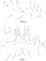
Figure 7 is a schematic side view of an apparatus made according to a second embodiment of this invention; -
Figure 8 is a front view of an alternative embodiment of the apparatus ofFigure 7 with some parts cut away to better illustrate others; and -
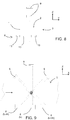
Figure 9 shows the combined effect of three emissions/readings relating to the same portion of a wooden plank. - To make the explanation of this invention clearer, hereinafter there is first an explanation of the principle of physics on which it is based, then of the apparatus made according to this invention and finally of the method.
- As is known, the dielectric behaviour of wood is anisotropic. Consequently, it is possible to represent it using a characteristic surface, as is normally the case for any property of anisotropic materials. In the case of the dielectric behaviour of wood, given the dielectric tensor ε which describes the interaction of the wood with an external electric field depending on its orientation, its variation in space may be represented by the surface of an ellipsoid which represents the locus of the vertices of the tensor ε. The ellipsoid is positioned with its semi-axes oriented depending on the orientation of the wood fibres.
- In particular, it is possible to identify a longitudinal semi-axis (extending along direction L in
Figure 2 ) which is parallel with the direction of the wood fibres, a radial semi-axis (extending along direction R inFigure 2 ) and a tangential semi-axis (extending along direction T inFigure 2 ); the respective lengths being:
- However, the radial and tangential dielectric properties are very similar and may therefore be considered substantially equal and defined overall as properties which are perpendicular (⊥) to the direction of the grain. In line with that, the longitudinal property may also be defined as a property which is parallel (∥) with the direction of the grain. Therefore, the respective dielectric constants will be ε⊥ and ε∥.
- As shown in
Figures 2 to 5 , the ellipsoid is oriented depending on the spatial orientation of the wood fibres with the shortest semi-axis, corresponding to ε∥, aligned with the direction of the grain L. The ellipsoid is therefore a sort of disk whose axis of symmetry coincides with the direction of extension of the fibres L. - The first idea which forms the basis of this invention is that to determine the orientation of the fibres it is sufficient to determine the orientation of the ellipsoid which represents the dielectric tensor ε. In fact, the direction of the smallest semi-axis coincides with the direction of the fibres L.
- The second idea which forms the basis of this invention is that to determine the three-dimensional orientation of the fibres of the wood, the problem may be broken down by separately determining two projections of the direction of the grain L on two planes which are perpendicular, as shown in
Figure 1 where the angle υ represents the projection on a first flat face 2 (parallel to plane XY inFigure 1 ) of theplank 1, and the angle ω represents the projection on a second flat face 3 (parallel to plane XZ inFigure 1 ) of theplank 1 which is orthogonal to the first 2. However, the angle υ corresponds to the horizontal angle and may therefore be determined using the prior art methods referred to above. - Consequently, to determine the three-dimensional orientation of the fibres it is sufficient to find a method for estimating the angle ω.
- The third idea which forms the basis of this invention is that the interaction between a beam of incident microwaves and a fibre of the wood, each having its own orientation in space, may be considered as a sort of projection of the ellipsoid. Conceptually, it is a situation similar to that of an object which produces different shadows if lit from different viewpoints. But in this case, the "shadow" is not the projection of the entire ellipsoid, but rather the projection of the ellipse which is obtained from the intersection of the ellipsoid with a plane passing through its centre and perpendicular to the direction of "lighting". Moreover, the projection is shown as a variation of the intensity and a phase shift of the incident wave.
- In light of those conditions, first what is usually a three-dimensional problem can be reduced to a two-dimensional problem by reasoning only with reference to the projections of the ellipsoid and of the dive angle on a reference plane XZ which is perpendicular to the
first face 2 of the plank 1 (the one against which the microwaves are directed). To do that, it can be sufficient to irradiate the wood from a single side for example the reference plane XZ with microwaves of defined polarization. In fact, in this way, rather than considering the entire ellipsoid it is possible to consider a single two-dimensional ellipse, the one identified by the intersection of the ellipsoid with a plane parallel with the reference plane XZ and passing through the centre of the ellipsoid. In the invention the microwaves are polarized exclusively in a plane parallel with the reference plane XZ. - Secondly, as shown in
Figure 6 , it is usually sufficient to irradiate with polarized microwaves the wood whose direction of grain L is to be determined in two directions Pα, Pβ which are incident on thefirst face 2 and which lie in a plane perpendicular to the first face 2 (and therefore parallel with the reference plane XZ). The two directions Pα, Pβ must also be set at a sufficient angle (αβ) to each other to provide two sufficiently separate projections of the relevant ellipsoid. Therefore, from the two projections it is possible to determine the tensors ε which are perpendicular to the directions of irradiation Pα, Pβ, from which the ellipse can be calculated which corresponds to the intersection of the ellipsoid with the vertical plane passing through its centre and parallel with the reference plane XZ. Once the ellipse is known, it is possible to determine the semi-axes, and the angle formed by the smallest semi-axis of the ellipse obtained in that way corresponds to the dive angle ω. In this greatly simplified model it is therefore sufficient to know the two projections in order to estimate the angle ω. - However, if the wood is irradiated according to a direction of incidence which is set at an angle to the first face 2 (that is to say, with angle of incidence ≠ 90°) it must be remembered that the microwaves are subject to refraction as they pass from the air to the wood and again when they pass back from wood to air. In fact, the angle with which the microwaves propagate in the wood is not the angle of incidence, but an angle ϕ (measured relative to a direction perpendicular to the first face 2) which depends also on density and degree of moisture of the wood, as known to the skilled person. Consequently, what is detected is not the dielectric response of the wood in the direction identified by the angle of incidence, but that in the direction identified by the angle ϕ.
- Moving on to the description of the
apparatus 4 for implementing this invention, it is illustrated as a whole inFigure 7 . - As indicated, the
apparatus 4 allows an estimate of the projection on a reference plane XZ of the direction of extension of the fibres L of a portion of awooden plank 1. - As shown in
Figure 1 , thewooden plank 1 has a nominal direction of the fibres N which is parallel with a main axis of extension of it and afirst face 2 which is also parallel with the main axis of extension (advantageously, thefirst face 2 is always one of the two opposite faces having the largest surface area). - The core of the
apparatus 4 is adevice 5 for examining awooden plank 1 which first comprises supportingmeans 6 for theplank 1 which define both a lying plane 7 (parallel to plane XY) on which, during operation, thefirst face 2 of theplank 1 or the face diametrically opposed to it lies, and a longitudinal axis which is parallel with the lying plane 7 (parallel with the sheet inFigure 7 ). In use, theplank 1 is placed on the supportingmeans 6 with the nominal direction of the fibres N parallel with the longitudinal axis. - The
device 5 also comprises both means for emitting 8 polarized microwave beams which are positioned on a first side of the lyingplane 7, and means for detecting 9 microwaves which are positioned on a second side of the lyingplane 7 which is opposite to the first side. In use, the detectingmeans 9 allow detection of the residual part of the polarized microwave beams emitted by the emitting means 8 after they have passed through theplank 1. For that purpose, the emitting means 8 and/or the detectingmeans 9 are distanced from the lyingplane 7 and between them and the lyingplane 7 form anoperating zone 10 where, in use, awooden plank 1 can be inserted. Moreover, in general, the emitting means 8 and the detectingmeans 9 are facing one another so as to define at least a first propagation plane in which one or more first directions of propagation, which can be parallel or diverging to each other, lie, and a second propagation plane (hereinafter also referred to simply as the first plane Pα and the second plane Pβ) in which one or more second directions of propagation, which can be parallel or diverging to each other, lie; moreover the first plane Pα and the second plane Pβ for the propagation of the microwave beams from the emitting means 8 to the detectingmeans 9, are separate and far enough apart. Both the first plane Pα and the second plane Pβ pass through the operatingzone 10. In most of the embodiments this result may be achieved mainly by using one of the following possible alternatives (even if hybrid solutions are also possible). - The first possibility is that the emitting means 8 comprise a microwave emitter for each propagation plane Pα, Pβ and that the detecting
means 9 also comprise a microwave detector for each propagation plane Pα, Pβ. - The second, preferred, possibility is that the emitting means 8 comprise a single microwave emitter for all of the propagation planes Pα, Pβ (which can therefore emit microwaves in all of the propagation planes Pα, Pβ to be used) and in contrast the detecting
means 9 comprise a microwave detector for each propagation plane. - Finally, the third possibility is that the detecting
means 9 comprise only a single microwave detector for all of the propagation planes Pα, Pβ (which can therefore receive from several directions) and the emitting means 8 comprise a separate microwave emitter for each propagation plane. - To guarantee reliable results, in general the first plane Pα forms a first minimum angle α1 with the lying plane 7 (that is to say, the smallest angle of the two α1, α2 formed by the first plane Pα with the lying plane 7) which is not less than 30° and which intersects the lying
plane 7 along a first line which is transversal, but preferably orthogonal, to the longitudinal axis (inFigure 7 it is orthogonal and is therefore perpendicular to the sheet and to plane XZ). Similarly, the second plane Pβ forms a second minimum angle β1 with the lying plane 7 (that is to say, the smallest angle of the two β1, β2 formed by the second plane Pβ with the lying plane 7) which is not less than 30° and which intersects the lyingplane 7 along a second transversal line which is parallel with the first transversal line. Advantageously, in the preferred embodiments, the first minimum angle α1 and the second minimum angle β1 are between 30° and 60°. Finally, the first planePα and the second plane Pβ between them form a third minimum angle (αβ) which is not less than 30°. - Depending on requirements, the emitting means 8 and the detecting
means 9 may either define only two propagation planes Pα, Pβ, or they may define three or more of them. In the former case, it is possible that both the first plane Pα and the second plane Pβ are angled on opposite sides relative to the lyingplane 7, advantageously forming the same minimum angle α1, β1 with it (symmetrical solution similar to that ofFigure 7 although in that Figure there is also a third plane Pγ), or that the first plane Pα is orthogonal to the lyingplane 7 and that the second minimum angle β1 is between 30° and 60°. However, the preferred embodiment of this invention is of the latter type and is schematically illustrated inFigure 7 . In this case, the emitting means 8 and the detectingmeans 9 are facing one another so as to also define a third propagation plane (in the following third plane Pγ) of the microwave beams from the emitting means 8 to the detectingmeans 9, the third plane Pγ being separate from the first plane Pα and the second plane Pβ and passing through the operatingzone 10. The first and second planes Pα, Pβ are angled on opposite sides relative to the lyingplane 7, and they form the same minimum angle α1, β1 with it and are symmetrical relative to the third plane Pγ. In fact, the latter is orthogonal to the lyingplane 7 and intersects the lyingplane 7 along a third line which is transversal to the nominal direction of the fibres N and also parallel with the first transversal line (therefore also perpendicular to the sheet inFigure 7 and to plane XZ). In this case the third plane Pγ forms both with the first plane Pα and with the second plane Pβ a fourth minimum angle αγ, γβ which is not less than 30°. Consequently, the first plane Pα and the second plane Pβ between them form a third minimum angle αβ of at least 60°. - Finally, in the preferred embodiment, to allow an analysis of the
entire plank 1, portion after portion, thedevice 5 also comprises translation means 11 for in use translating theplank 1 relative to the emitting means 8 and to the detectingmeans 9 or vice versa. In the case illustrated inFigure 7 the translation means 11 allow theplank 1 to be shifted parallel with the longitudinal axis and could consist of one or more conveyors (advantageously of the belt or chain type). - In the embodiment illustrated in
Figures 7 and8 , in particular the emitting means 8 comprise a single emitter, whilst the detectingmeans 9 comprise three detectors mounted on a single supportingstructure 12. The central detector is aligned with the emitter according to a propagation plane (the third plane Pγ) orthogonal to the lying plane 7 (and therefore in use to the first face 2), whilst the two lateral detectors are specular relative to one another and are aligned with the emitter according to propagation planes Pα, Pβ which form a 45° angle with the propagation plane Pγ of the central detector. - Depending on the embodiments, it is possible that each emitter comprises either a single emitting
antenna 13 as in the embodiment illustrated inFigure 7 (which advantageously covers the entire width of the plank 1) or two or more emittingantennas 13 which are aligned (as shown inFigure 8 ). However, in both cases the emitter advantageously extends parallel with the first transversal line. - In the same way, each receiver may also comprise one or more receiving antennas which are aligned in a direction parallel with the first transversal line. However, in the accompanying drawings each receiver comprises only a single receiving antenna whose width is less than that of the
plank 1. Returning to theapparatus 4 as a whole, in it thedevice 5 describe so far is mounted in such a way that the lyingplane 7 is orthogonal to the reference plane XZ and in such a way that the longitudinal axis is, in contrast, parallel with it. - The
apparatus 4 also comprises at least one electronic control andprocessing unit 14 operatively connected at least to the emitting means 8 and to the detectingmeans 9 and programmed to estimate the projection of the orientation of the fibres on the reference plane XZ by processing what was detected by the detectingmeans 9, and in particular by processing the amplitude and phase of the microwaves received. - However, in the preferred embodiment the electronic control and
processing unit 14 is programmed to implement at least the steps of emitting, detecting, determining and estimating of the method according to this invention and described below. - Therefore what follows is a description of the method according to this invention for estimating the projection on a reference plane XZ of the direction of extension of the fibres L of a portion of a
wooden plank 1. It shall be understood that what has already been described with reference to theapparatus 4 is also valid for corresponding elements of the method (that is to say, elements identified with the same definitions). - The method comprises first an operating step of identifying a portion of the
plank 1 for which the orientation of the projection is to be estimated (as indicated below, the estimate of the projection for theentire plank 1 can be carried out as a sequence of estimates for individual portions), and an operating step of placing theplank 1 with itsfirst face 2 orthogonal to the reference plane XZ and with the main axis of extension parallel with the reference plane XZ. If theapparatus 4 described above is being used, that is achieved by placing thefirst face 2, or the face opposite to and parallel with it, on the lyingplane 7. - At this point the method comprises a first operating step of emitting at least a first polarized microwave beam (advantageously with plane/linear polarization in one plane) towards the portion of the
plank 1 being examined, according to a first direction of incidence which lies in a first propagation plane Pα. As already indicated, the first plane Pα will form a first minimum angle α1 with thefirst face 2 which is not less than 30° and will intersect thefirst face 2 along the first transversal line. - Simultaneously or at a different time, the method comprises a second operating step of emitting at least a second polarized microwave beam (advantageously with polarization similar to that of the first beam) towards the portion of the
plank 1 being examined, according to a second direction of incidence which lies in a second propagation plane Pβ. As already indicated, the second plane Pβ will form a second minimum angle β1 with thefirst face 2 which is not less than 30° and will intersect thefirst face 2 along the second transversal line. Moreover, the second plane Pβ will form with the first plane Pα a third minimum angle αβ which is not less than 30°. - Reference should be made to what is described above regarding the possible orientations of the first plane Pα and the second plane Pβ.
- Substantially simultaneously respectively with the first and second emitting steps (except for the delay due to the time taken by the microwaves to travel from the emitter to the receiver), the method comprises a first operating step of detecting, on the opposite side of the wood to that where the microwaves entered, the residual part of the first beam which passed through the
plank 1, and a second operating step of detecting, again on the opposite side of the wood to that where the microwaves entered, the residual part of the second beam which passed through theplank 1. - At that point, the method comprises a first operating step of determining the amplitude and the phase of the residual part of the first beam which passed through the plank 1 (hereinafter indicated as the first amplitude and the first phase) and a second operating step of determining the amplitude and the phase of the residual part of the second beam which passed through the plank 1 (hereinafter indicated as the second amplitude and the second phase).
- Finally, the method comprises an operating step of estimating the orientation of the projection of the direction of the fibres L on the reference plane XZ, by processing the first and second amplitudes and the first and second phases previously determined. That processing is effectively used to determine the projection on the reference plane XZ of the direction of the smallest semi-axis of the ellipsoid characteristic of the dielectric tensor of the wood.
- However, in the preferred embodiment the method also comprises a third operating step of emitting at least a third polarized microwave beam (in a similar way to the first two) towards the portion of
plank 1 being examined, according to a third direction of incidence which lies in a third plane Pγ orthogonal to thefirst face 2 and which intersects thefirst face 2 along the third transversal line. As already indicated, the third plane Pγ will form both with the first plane Pα and with the second plane Pβ a fourth minimum angle αγ, γβ which is not less than 30°, advantageously equal with both. - Consequently, the method comprises a third operating step of detecting, on the opposite side to the
first face 2, the residual part of the third beam which passed through theplank 1, and a third operating step of determining the amplitude and the phase of that residual part detected (hereinafter indicated as the third amplitude and the third phase). - In this more complete embodiment of the method, the step of estimating the projection occurs by means of processing of the first, second and third amplitudes and of the first, second and third phases previously determined. The aim (implicit or explicit) is always to determine the smallest semi-axis of the ellipsoid.
- Depending on the embodiments, it may be appropriate that the steps of emitting, and detecting of each beam occur either while keeping the
plank 1 stationary relative to the various beams (which may be generated either simultaneously or one after another) or translating theplank 1 after each beam has been emitted (therefore, the various beams will be emitted one after another). - That is due to the need to allow the beams to pass through the same fibres of the wood as far as possible. In fact, as is easy to infer, since the propagation planes are angled relative to each other, it is not possible to make each beam pass through exactly the same fibres of wood and only those fibres.
-
Figure 9 illustrates that circumstance with reference to three beams lying in planes Pα, Pβ, Pγ angled at 45° to one another which intersect at the centre of theplank 1. As can be seen, only the hatched portion of wood is common to the three beams. Other portions are only common to two beams, whilst still others only have one beam passing through them. The situation schematically illustrated inFigure 9 may be obtained both by using three separate emitters and three separate receivers which are suitably positioned, or with a single emitter (or detector) and three receivers (or respectively, emitters) which are arranged as shown inFigure 7 . In former caseFigure 7 effectively shows the structure of theapparatus 4 which can be used to implement the method, whilst in the latter caseFigure 9 shows the superposing in a single view of three different moments which correspond to threedifferent plank 1 positions. In particular, considering the continuous line rectangle below theplank 1 to be a single emitter, and the rectangles above theplank 1 to be receivers, the continuous line upper rectangle represents the receiver towards which the third beam propagates at the moment to. The dashed line receiver to the left of the continuous line receiver represents the receiver towards which the first beam propagates at the moment t0-Δt, whilst the dashed line receiver to the right represents the receiver towards which the first beam propagates at the moment t0+Δt. - The assessments would be the same considering a situation with a single receiver below the
plank 1 and three emitters above it. - Therefore, in the application of the method according to this invention the first, second and third amplitudes and phases must always be assessed with reference to the same portion of plank 1 (or rather, with reference to microwave beams which pass through not just other wood but also a common portion - the portion hatched in
Figure 9 ). - However, in the preferred embodiment the steps of emitting, detecting and determining relating to each beam are carried out for a plurality of separate portions of the
plank 1. That is advantageously achieved by repeating the various steps by making theplank 1 translate longitudinally, at least in a relative fashion, and repeating the various steps at preset time intervals. - In general, if each emitter comprises two or more emitting
antennas 13, it is also possible that: - each emitting step involves the successive emission of a plurality of microwave sub-beams;
- each emitting step involves the emitting one after another of each sub-beam towards the portion of the
wooden plank 1 or a part of it; - each detecting step involves the detection one after another of the residual part of each sub-beam which passed through the
plank 1; and - each determining step involves determining the amplitude and the phase corresponding to those of the residual part of each sub-beam which passed through the
plank 1. Advantageously, each sub-beam is directed towards a part of the portion ofplank 1 which is at least partly separate from that towards which the other sub-beams of the same beam are directed (the portion ofplank 1 is basically examined at a plurality of slices which are side by side and aligned parallel with the transversal lines). Finally, in this embodiment the step of estimating the projection is carried out by means of processing of the amplitudes and phases determined in this way. - Finally, the following is a description of a preferred embodiment of the method according to this invention, which may be implemented using an
apparatus 4 similar to that illustrated inFigure 7 or8 . - The configuration selected therefore requires the use of three receivers, each consisting of a single receiving antenna, and the use of a single emitter which may comprise one or more emitting
antennas 13 which are aligned in a row. The emitter is located below theplank 1, the receivers above and the propagation planes of the various beams are one perpendicular to thefirst face 2, and the other two specular and angled on opposite sides relative to the central one. Of course, in different embodiments, receivers can be placed below theplank 1 with the emitter above, as well as only one receiver and three emitters can be used. - T(r,t) is the overall number which represents the amplitude and the phase of the signal received by each receiver "r", transmitted by each emitting
antenna 13 "t", where: - the value of "r" may be 1 (first angled receiver), 2 (vertical receiver) or 3 (second angled receiver); and
- the value of "t" is from 1 to n, where n is the total number of emitting
antennas 13 in the row; - Both the emitting
antennas 13 and the receivers are also polarized in a plane perpendicular to thefirst face 2 and parallel with the nominal direction of the fibres N. - At that point, for each emitting antenna 13 (k=1..n), the angle ω formed by the projection of the direction of the fibres L on the reference plane XZ, relative to the nominal direction N, is:



Figure 6 ). The angle ϕ, which is determined by refraction phenomena, depends both on the type of wood, its density and its degree of moisture, and on the angle of incidence formed by the first plane Pα and by the second plane Pβ with thefirst face 2 of theplank 1. - This invention brings important advantages.
- In fact, the method, the apparatus and the device according to this invention allow estimation of the projection on a reference plane of the direction of extension of the fibres of a portion of a wooden plank, examining a face of the plank which is orthogonal to the reference plane, and in particular they allow the determination of the dive angle relative to a main face of the plank by emitting the microwaves from above against said main face.
- Finally, it should be noticed that this invention is relatively easy to produce and that even the cost linked to implementing the invention is not very high. The invention described above may be modified and adapted in several ways without thereby departing from the scope of the inventive concept. Moreover, all details of the invention may be substituted with other technically equivalent elements and the materials used, as well as the shapes and dimensions of the various components, may vary according to requirements.
Claims (14)
- A method for estimating the projection on a reference plane (XZ) of the direction of extension of the fibres (L) of a portion of a wooden plank (1), the wooden plank (1) having a main axis of extension, a first flat face (2) which is parallel with the main axis of extension and a nominal direction of the fibres (N) which is defined as parallel with the main axis of extension, the fibres having an orientation in space with any deviation relative to the nominal direction, the method comprising:an operating step of identifying a portion of the plank (1) for which the orientation of said projection is to be estimated;an operating step of placing the plank (1) with its first face (2) orthogonal to the reference plane (XZ) and with the main axis of extension parallel with the reference plane (XZ);the method further comprising:an operating step of emitting at least a first polarized microwave beam towards said portion of the plank (1) according to a first direction of incidence lying in a first plane (Pα) which forms a first minimum angle (α1) with said first face (2) which is not less than 30° and which intersects the first face (2) along a first line transversal to the nominal direction of the fibres (N), the first polarized microwave beam being emitted in such a way to enter the plank (1) through the first face (2); said first polarized microwave beam being polarized exclusively in a plane parallel with the reference plane (XZ);an operating step of emitting at least a second polarized microwave beam towards said portion of the plank (1) according to a second direction of incidence lying in a second plane (Pβ) which forms a second minimum angle (β1) with said first face (2) which is not less than 30° and which intersects the first face (2) along a second line transversal to the nominal direction of the fibres (N) and parallel with the first transversal line, the second polarized microwave beam being emitted in such a way to enter the plank (1) through the first face (2); the second plane (Pβ) also forming with the first plane (Pα) a third minimum angle (αβ) which is not less than 30°; said second polarized microwave beam being polarized exclusively in a plane parallel with the reference plane (XZ);an operating step of detecting the residual part of the first beam which passed through the plank (1);an operating step of detecting the residual part of the second beam which passed through the plank (1);an operating step of determining a first amplitude and a first phase corresponding to those of the residual part of the first beam which passed through the plank (1);an operating step of determining a second amplitude and a second phase corresponding to those of the residual part of the second beam which passed through the plank (1); andan operating step of processing the first and second amplitudes and the first and second phases previously determined, to estimate the orientation of the projection of the direction of extension of the fibres (L) on the reference plane (XZ) which is orthogonal to the first face (2).
- The method according to claim 1, characterised:in that the first plane (Pα) and the second plane (Pβ) are selected in such a way that they form the first minimum angle (α1) and the second minimum angle (β1) respectively on opposite sides with respect to a plane perpendicular to the nominal direction of the fibres (N); and/orin that the first plane (Pα) and the second plane (Pβ) are selected in such a way that the first minimum angle (α1) is equal to the second minimum angle (β1); and/orin that the first minimum angle (α1) and the second minimum angle (β1) are selected so that they are between 30° and 60°; orin that the first plane (Pα) is selected orthogonal to the first face (2), and in that the second minimum angle (β1) is selected so that it is between 30° and 60°.
- The method according to claim 1, characterised in that the first plane (Pα) and the second plane (Pβ) are selected in such a way that the first minimum angle (α1) is equal to the second minimum angle (β1), and in that it also comprises:an operating step of emitting at least a third polarized microwave beam towards said portion of the plank (1) according to a third direction of incidence lying in a third plane (Pγ) which is orthogonal to the first face (2) and which intersects the first face (2) along a third line transversal to the nominal direction of the fibres (N) and parallel with the first transversal line; the third plane (Pγ) forming with both the first plane (Pα) and the second plane (Pβ) a fourth minimum angle (αγ, γβ) which is not less than 30°;an operating step of detecting the residual part of the third beam which passed through the plank (1); andan operating step of determining a third amplitude and a third phase corresponding to those of the residual part of the third beam which passed through the plank (1);and in that the third amplitude and the third phase previously determined are processed together with the first and second amplitudes and the first and second phases, in order to estimate the orientation of said projection.
- The method according to claims 3 , characterised in that the third beam has the same polarization as the first and second beams.
- The method according to any one of the preceding claims, characterised in that the first transversal line is selected orthogonal to the nominal direction of the fibres (N).
- The method according to any one of the preceding claims, characterised in that:each emitting step involves the emitting one after another of a plurality of microwave sub-beams towards a part of the portion of plank (1) which is at least partly shifted along a direction perpendicular to the reference plane (XZ) with respect to that towards which the other sub-beams of the same beam are directed;each detecting step involves the detection one after another of the residual part of each sub-beam which passed through the plank (1);each determining step involves determining the amplitude and the phase corresponding to those of the residual part of each sub-beam which passed through the plank (1); andthe amplitudes and phases determined in this way are processed in order to estimate the orientation of said projection.
- A device for examining the direction of extension of the fibres (L) of a wooden plank (1), comprising:supporting means (6) for the plank (1) which define both a lying plane (7) and a longitudinal axis, the supporting means being suitable to receive the plank (1) in such a way that, during operation, the plank (1) lies with a first flat face (2) parallel with the lying plane (7) and a nominal direction of the fibres (N), which is defined as parallel with a main axis of extension of the plank (1) that is also parallel with the first flat face (2), is parallel with the longitudinal axis;means for emitting (8) polarized microwave beams which are positioned on a first side of the lying plane (7); said polarized microwave beams being polarized exclusivelyin a plane parallel with a reference plane (XZ) which is orthogonal to the lying plane (7) and parallel with the longitudinal axis;means for detecting (9) microwaves which are positioned on a second side of the lying plane (7) opposite to the first side, for in use detecting the residual part of the polarized microwave beams emitted by the emitting means (8) after they have passed through the plank (1);the emitting means (8) and/or the detecting means (9) being distanced from the lying plane (7) and between them and the lying plane (7) forming an operating zone (10) where, in use, the wooden plank (1) can be inserted;the emitting means (8) and the detecting means (9) facing one another so as to define at least a first plane (Pα) and a second plane (Pβ) which are separate for the propagation of the microwave beams from the emitting means (8) to the detecting means (9), both of said planes passing through the operating zone (10);wherein:the first plane (Pα) intersects the lying plane (7) along a first line which is transversal to the longitudinal axis, forming a first minimum angle (α1) with the lying plane (7) which is not less than 30°; andthe second plane (Pβ) intersects the lying plane (7) along a second transversal line which is transversal to the longitudinal axis and parallel with the first transversal line, forming a second minimum angle (β1) with the lying plane (7) which is not less than 30°, the second plane (Pβ) also forming with the first plane (Pα) a third minimum angle (αβ) which is not less than 30°.
- The device according to claim 7, characterised:in that the first plane (Pα) and the second plane (Pβ) form the first minimum angle (α1) and the second minimum angle (β1) respectively on opposite sides with respect to a plane perpendicular to the nominal direction of the fibres (N); and/orin that the first minimum angle (α1) is equal to the second minimum angle (β1); and/orin that the first minimum angle (α1) and the second minimum angle (β1) are between 30° and 60°; or in that the first plane (Pα) is orthogonal to the lying plane (7), and in that the second minimum angle (β1) is between 30° and 60°.
- The device according to claim 8, characterised in that the first minimum angle (α1) is equal to the second minimum angle (β1) and in that the emitting means (8) and the detecting means (9) are facing one another so as to also define at least a third plane (Pγ) for propagation of the microwave beams from the emitting means (8) to the detecting means (9), separate from the first plane (Pα) and from the second plane (Pβ) and passing through the operating zone (10); the third plane (Pγ) being orthogonal to the lying plane (7) and intersecting the lying plane (7) along a third line transversal to the nominal direction of the fibres (N) and parallel with the first transversal line; the third plane (Pγ) forming both with the first plane (Pα) and with the second plane (Pβ) a fourth minimum angle which is not less than 30°.
- The device according to any one of the claims from 7 to 9, characterised in that the first transversal line is orthogonal to the longitudinal axis.
- The device according to any one of the claims from 7 to 10, characterised in that alternatively:- the emitting means (8) comprise a microwave emitter for each propagation plane and the detecting means (9) comprise a microwave detector for each propagation plane; or- the emitting means (8) comprise a single microwave emitter for all of the propagation planes and the detecting means (9) comprise a microwave detector for each propagation plane; or- the detecting means (9) comprise a single microwave detector for all of the propagation planes and the emitting means (8) comprise a microwave emitter for each propagation plane.
- The device according to claim 11, characterised in that each emitter comprises one or more emitting antennas (13) which are aligned in a direction parallel with the first transversal line, and/or in that each emitter comprises one or more emitting antennas (13) which are aligned in a direction parallel with the first transversal line and each receiver comprises one or more receiving antennas which are aligned in a direction parallel with the first transversal line.
- An apparatus for estimating the projection on a reference plane (XZ) of the direction of extension of the fibres (L) of a portion of a wooden plank (1), the wooden plank (1) having a nominal direction of the fibres (N) which is parallel with a main axis of extension of it and a first face (2) which is also parallel with the main axis of extension;
the apparatus (4) comprising:at least one device (5) made according to any one of the claims from 7 to 12,; andat least one electronic control and processing unit (14) operatively connected at least to the emitting means (8) and to the detecting means (9) and programmed to process what was detected by the detecting means (9) in order to estimate said projection. - The apparatus according to claim 13, characterised in that the electronic control and processing unit (14) is programmed to implement at least the steps of emitting, detecting, determining and processing of the method according to any one of the claims from 1 to 6.
Applications Claiming Priority (1)
| Application Number | Priority Date | Filing Date | Title |
|---|---|---|---|
| IT000037A ITBZ20130037A1 (en) | 2013-07-25 | 2013-07-25 | METHOD AND EQUIPMENT TO ESTIMATE THE PROJECTION ON A REFERENCE PLAN OF THE FIBER DEVELOPMENT DIRECTION OF A PORTION OF A WOODEN TABLE |
Publications (2)
| Publication Number | Publication Date |
|---|---|
| EP2829876A1 EP2829876A1 (en) | 2015-01-28 |
| EP2829876B1 true EP2829876B1 (en) | 2017-08-30 |
Family
ID=49085081
Family Applications (1)
| Application Number | Title | Priority Date | Filing Date |
|---|---|---|---|
| EP14178236.7A Active EP2829876B1 (en) | 2013-07-25 | 2014-07-23 | Method and apparatus for estimating the projection on a reference plane of the direction of extension of the fibres of a portion of a wooden plank |
Country Status (2)
| Country | Link |
|---|---|
| EP (1) | EP2829876B1 (en) |
| IT (1) | ITBZ20130037A1 (en) |
Family Cites Families (5)
| Publication number | Priority date | Publication date | Assignee | Title |
|---|---|---|---|---|
| FI57490C (en) | 1978-06-01 | 1980-08-11 | Innotec Oy | FOERFARANDE FOER BESTAEMNING AV SNEDFIBRIGHETEN I VIRKE I SYNNERHET I SAOGAT VIRKE |
| US4514680A (en) * | 1983-01-28 | 1985-04-30 | A.Ahlstrom Osakeyhtio | Flaw detection system using microwaves |
| WO1990009578A1 (en) | 1989-02-14 | 1990-08-23 | Commonwealth Scientific And Industrial Research Organisation | Microwave scanning apparatus |
| US6842010B2 (en) * | 2002-05-31 | 2005-01-11 | Precarn Incorporated | Method and apparatus to evaluate dielectrically-anisotropic materials using analysis of multiple microwave signals in different planes of polarization |
| CA2388394C (en) | 2002-05-31 | 2009-02-10 | Precarn Incorporated | Method and apparatus for evaluating anisotropic materials |
-
2013
- 2013-07-25 IT IT000037A patent/ITBZ20130037A1/en unknown
-
2014
- 2014-07-23 EP EP14178236.7A patent/EP2829876B1/en active Active
Non-Patent Citations (1)
| Title |
|---|
| None * |
Also Published As
| Publication number | Publication date |
|---|---|
| ITBZ20130037A1 (en) | 2015-01-26 |
| EP2829876A1 (en) | 2015-01-28 |
Similar Documents
| Publication | Publication Date | Title |
|---|---|---|
| Riggio et al. | Application of imaging techniques for detection of defects, damage and decay in timber structures on-site | |
| Vössing et al. | Nondestructive assessment and imaging methods for internal inspection of timber. A review. | |
| Li et al. | Analysis of wave velocity patterns in black cherry trees and its effect on internal decay detection | |
| EP2530458B1 (en) | Method and device for measuring basis weight and water content amount | |
| JP5347896B2 (en) | Nondestructive inspection method and apparatus | |
| US10753895B2 (en) | Orientation evaluation device, orientation evaluation method, and distribution evaluation device | |
| JP2011017565A (en) | Optical quality evaluation method of wood | |
| EP3940338B1 (en) | Characterizing internal structures via ultrasound | |
| Pahnabi et al. | Imaging of structural timber based on in situ radar and ultrasonic wave measurements: A review of the state-of-the-art | |
| Riggio et al. | Structural health assessment of historical timber structures combining non‐destructive techniques: The roof of Giotto's bell tower in Florence | |
| Li et al. | Stress wave velocity patterns in the longitudinal–radial plane of trees for defect diagnosis | |
| Gao et al. | Application of an ultrasonic wave propagation field in the quantitative identification of cavity defect of log disc | |
| Zhang et al. | Experimental investigation of stress wave propagation in standing trees | |
| Mills et al. | Residual stress analysis in robotically welded plates using phased array ultrasonics with validation through neutron diffraction and hole-drilling methods | |
| Mieloszyk et al. | Structural analyses of additively manufactured carbon fiber reinforced polymer with embedded fiber optic using THz spectroscopy and micro-computed tomography | |
| EP2829876A1 (en) | Method and apparatus for estimating the projection on a reference plane of the direction of extension of the fibres of a portion of a wooden plank | |
| EP3351928B1 (en) | X-ray sidescatter inspection of laminates | |
| Bogosanovic et al. | Overview and comparison of microwave noncontact wood measurement techniques | |
| KR101795992B1 (en) | Device for analyzing tubular specimen using terahertz wave and method for analyzing tubular specimen using the device | |
| Denzler et al. | Microwave scanning as an additional grading principle for sawn timber | |
| Reid et al. | Terahertz applications in the wood products industry | |
| US12203892B1 (en) | Detection and monitoring of cracks and fractures using nonlinear response to multimode acoustic signals | |
| Liu et al. | Measuring low-level porosity structures by using a non-destructive terahertz inspection system | |
| Lundgren | Microwave sensors for scanning of sawn timber | |
| Beni et al. | First trials for a microwave reflectometric tool to survey decay in historic timber structures |
Legal Events
| Date | Code | Title | Description |
|---|---|---|---|
| 17P | Request for examination filed |
Effective date: 20140723 |
|
| AK | Designated contracting states |
Kind code of ref document: A1 Designated state(s): AL AT BE BG CH CY CZ DE DK EE ES FI FR GB GR HR HU IE IS IT LI LT LU LV MC MK MT NL NO PL PT RO RS SE SI SK SM TR |
|
| AX | Request for extension of the european patent |
Extension state: BA ME |
|
| PUAI | Public reference made under article 153(3) epc to a published international application that has entered the european phase |
Free format text: ORIGINAL CODE: 0009012 |
|
| RIN1 | Information on inventor provided before grant (corrected) |
Inventor name: ARTHABER, HOLGER Inventor name: LEDER, NORBERT Inventor name: DENZLER, JULIA Inventor name: KOPPENSTEINER, JOHANNES Inventor name: WEIDENHILLER, ANDREAS |
|
| RIN1 | Information on inventor provided before grant (corrected) |
Inventor name: WEIDENHILLER, ANDREAS Inventor name: DENZLER, JULIA Inventor name: ARTHABER, HOLGER Inventor name: KOPPENSTEINER, JOHANNES Inventor name: LEDER, NORBERT |
|
| R17P | Request for examination filed (corrected) |
Effective date: 20150723 |
|
| RBV | Designated contracting states (corrected) |
Designated state(s): AL AT BE BG CH CY CZ DE DK EE ES FI FR GB GR HR HU IE IS IT LI LT LU LV MC MK MT NL NO PL PT RO RS SE SI SK SM TR |
|
| 17Q | First examination report despatched |
Effective date: 20160318 |
|
| GRAP | Despatch of communication of intention to grant a patent |
Free format text: ORIGINAL CODE: EPIDOSNIGR1 |
|
| INTG | Intention to grant announced |
Effective date: 20170208 |
|
| GRAS | Grant fee paid |
Free format text: ORIGINAL CODE: EPIDOSNIGR3 |
|
| GRAA | (expected) grant |
Free format text: ORIGINAL CODE: 0009210 |
|
| AK | Designated contracting states |
Kind code of ref document: B1 Designated state(s): AL AT BE BG CH CY CZ DE DK EE ES FI FR GB GR HR HU IE IS IT LI LT LU LV MC MK MT NL NO PL PT RO RS SE SI SK SM TR |
|
| REG | Reference to a national code |
Ref country code: GB Ref legal event code: FG4D |
|
| REG | Reference to a national code |
Ref country code: CH Ref legal event code: EP |
|
| REG | Reference to a national code |
Ref country code: AT Ref legal event code: REF Ref document number: 924049 Country of ref document: AT Kind code of ref document: T Effective date: 20170915 |
|
| REG | Reference to a national code |
Ref country code: IE Ref legal event code: FG4D |
|
| REG | Reference to a national code |
Ref country code: DE Ref legal event code: R096 Ref document number: 602014013722 Country of ref document: DE |
|
| REG | Reference to a national code |
Ref country code: NL Ref legal event code: MP Effective date: 20170830 |
|
| REG | Reference to a national code |
Ref country code: LT Ref legal event code: MG4D |
|
| REG | Reference to a national code |
Ref country code: AT Ref legal event code: MK05 Ref document number: 924049 Country of ref document: AT Kind code of ref document: T Effective date: 20170830 |
|
| PG25 | Lapsed in a contracting state [announced via postgrant information from national office to epo] |
Ref country code: NO Free format text: LAPSE BECAUSE OF FAILURE TO SUBMIT A TRANSLATION OF THE DESCRIPTION OR TO PAY THE FEE WITHIN THE PRESCRIBED TIME-LIMIT Effective date: 20171130 Ref country code: FI Free format text: LAPSE BECAUSE OF FAILURE TO SUBMIT A TRANSLATION OF THE DESCRIPTION OR TO PAY THE FEE WITHIN THE PRESCRIBED TIME-LIMIT Effective date: 20170830 Ref country code: HR Free format text: LAPSE BECAUSE OF FAILURE TO SUBMIT A TRANSLATION OF THE DESCRIPTION OR TO PAY THE FEE WITHIN THE PRESCRIBED TIME-LIMIT Effective date: 20170830 Ref country code: AT Free format text: LAPSE BECAUSE OF FAILURE TO SUBMIT A TRANSLATION OF THE DESCRIPTION OR TO PAY THE FEE WITHIN THE PRESCRIBED TIME-LIMIT Effective date: 20170830 Ref country code: SE Free format text: LAPSE BECAUSE OF FAILURE TO SUBMIT A TRANSLATION OF THE DESCRIPTION OR TO PAY THE FEE WITHIN THE PRESCRIBED TIME-LIMIT Effective date: 20170830 Ref country code: LT Free format text: LAPSE BECAUSE OF FAILURE TO SUBMIT A TRANSLATION OF THE DESCRIPTION OR TO PAY THE FEE WITHIN THE PRESCRIBED TIME-LIMIT Effective date: 20170830 |
|
| PG25 | Lapsed in a contracting state [announced via postgrant information from national office to epo] |
Ref country code: GR Free format text: LAPSE BECAUSE OF FAILURE TO SUBMIT A TRANSLATION OF THE DESCRIPTION OR TO PAY THE FEE WITHIN THE PRESCRIBED TIME-LIMIT Effective date: 20171201 Ref country code: BG Free format text: LAPSE BECAUSE OF FAILURE TO SUBMIT A TRANSLATION OF THE DESCRIPTION OR TO PAY THE FEE WITHIN THE PRESCRIBED TIME-LIMIT Effective date: 20171130 Ref country code: LV Free format text: LAPSE BECAUSE OF FAILURE TO SUBMIT A TRANSLATION OF THE DESCRIPTION OR TO PAY THE FEE WITHIN THE PRESCRIBED TIME-LIMIT Effective date: 20170830 Ref country code: RS Free format text: LAPSE BECAUSE OF FAILURE TO SUBMIT A TRANSLATION OF THE DESCRIPTION OR TO PAY THE FEE WITHIN THE PRESCRIBED TIME-LIMIT Effective date: 20170830 Ref country code: IS Free format text: LAPSE BECAUSE OF FAILURE TO SUBMIT A TRANSLATION OF THE DESCRIPTION OR TO PAY THE FEE WITHIN THE PRESCRIBED TIME-LIMIT Effective date: 20171230 Ref country code: ES Free format text: LAPSE BECAUSE OF FAILURE TO SUBMIT A TRANSLATION OF THE DESCRIPTION OR TO PAY THE FEE WITHIN THE PRESCRIBED TIME-LIMIT Effective date: 20170830 |
|
| PG25 | Lapsed in a contracting state [announced via postgrant information from national office to epo] |
Ref country code: NL Free format text: LAPSE BECAUSE OF FAILURE TO SUBMIT A TRANSLATION OF THE DESCRIPTION OR TO PAY THE FEE WITHIN THE PRESCRIBED TIME-LIMIT Effective date: 20170830 |
|
| PG25 | Lapsed in a contracting state [announced via postgrant information from national office to epo] |
Ref country code: RO Free format text: LAPSE BECAUSE OF FAILURE TO SUBMIT A TRANSLATION OF THE DESCRIPTION OR TO PAY THE FEE WITHIN THE PRESCRIBED TIME-LIMIT Effective date: 20170830 Ref country code: CZ Free format text: LAPSE BECAUSE OF FAILURE TO SUBMIT A TRANSLATION OF THE DESCRIPTION OR TO PAY THE FEE WITHIN THE PRESCRIBED TIME-LIMIT Effective date: 20170830 Ref country code: DK Free format text: LAPSE BECAUSE OF FAILURE TO SUBMIT A TRANSLATION OF THE DESCRIPTION OR TO PAY THE FEE WITHIN THE PRESCRIBED TIME-LIMIT Effective date: 20170830 Ref country code: PL Free format text: LAPSE BECAUSE OF FAILURE TO SUBMIT A TRANSLATION OF THE DESCRIPTION OR TO PAY THE FEE WITHIN THE PRESCRIBED TIME-LIMIT Effective date: 20170830 |
|
| PG25 | Lapsed in a contracting state [announced via postgrant information from national office to epo] |
Ref country code: SK Free format text: LAPSE BECAUSE OF FAILURE TO SUBMIT A TRANSLATION OF THE DESCRIPTION OR TO PAY THE FEE WITHIN THE PRESCRIBED TIME-LIMIT Effective date: 20170830 Ref country code: SM Free format text: LAPSE BECAUSE OF FAILURE TO SUBMIT A TRANSLATION OF THE DESCRIPTION OR TO PAY THE FEE WITHIN THE PRESCRIBED TIME-LIMIT Effective date: 20170830 Ref country code: EE Free format text: LAPSE BECAUSE OF FAILURE TO SUBMIT A TRANSLATION OF THE DESCRIPTION OR TO PAY THE FEE WITHIN THE PRESCRIBED TIME-LIMIT Effective date: 20170830 Ref country code: IT Free format text: LAPSE BECAUSE OF FAILURE TO SUBMIT A TRANSLATION OF THE DESCRIPTION OR TO PAY THE FEE WITHIN THE PRESCRIBED TIME-LIMIT Effective date: 20170830 |
|
| REG | Reference to a national code |
Ref country code: DE Ref legal event code: R097 Ref document number: 602014013722 Country of ref document: DE |
|
| PLBE | No opposition filed within time limit |
Free format text: ORIGINAL CODE: 0009261 |
|
| STAA | Information on the status of an ep patent application or granted ep patent |
Free format text: STATUS: NO OPPOSITION FILED WITHIN TIME LIMIT |
|
| REG | Reference to a national code |
Ref country code: FR Ref legal event code: PLFP Year of fee payment: 5 |
|
| 26N | No opposition filed |
Effective date: 20180531 |
|
| PG25 | Lapsed in a contracting state [announced via postgrant information from national office to epo] |
Ref country code: SI Free format text: LAPSE BECAUSE OF FAILURE TO SUBMIT A TRANSLATION OF THE DESCRIPTION OR TO PAY THE FEE WITHIN THE PRESCRIBED TIME-LIMIT Effective date: 20170830 |
|
| REG | Reference to a national code |
Ref country code: CH Ref legal event code: PL |
|
| GBPC | Gb: european patent ceased through non-payment of renewal fee |
Effective date: 20180723 |
|
| PG25 | Lapsed in a contracting state [announced via postgrant information from national office to epo] |
Ref country code: MC Free format text: LAPSE BECAUSE OF FAILURE TO SUBMIT A TRANSLATION OF THE DESCRIPTION OR TO PAY THE FEE WITHIN THE PRESCRIBED TIME-LIMIT Effective date: 20170830 |
|
| REG | Reference to a national code |
Ref country code: BE Ref legal event code: MM Effective date: 20180731 |
|
| REG | Reference to a national code |
Ref country code: IE Ref legal event code: MM4A |
|
| PG25 | Lapsed in a contracting state [announced via postgrant information from national office to epo] |
Ref country code: IE Free format text: LAPSE BECAUSE OF NON-PAYMENT OF DUE FEES Effective date: 20180723 Ref country code: GB Free format text: LAPSE BECAUSE OF NON-PAYMENT OF DUE FEES Effective date: 20180723 Ref country code: CH Free format text: LAPSE BECAUSE OF NON-PAYMENT OF DUE FEES Effective date: 20180731 Ref country code: LI Free format text: LAPSE BECAUSE OF NON-PAYMENT OF DUE FEES Effective date: 20180731 |
|
| PG25 | Lapsed in a contracting state [announced via postgrant information from national office to epo] |
Ref country code: BE Free format text: LAPSE BECAUSE OF NON-PAYMENT OF DUE FEES Effective date: 20180731 |
|
| PG25 | Lapsed in a contracting state [announced via postgrant information from national office to epo] |
Ref country code: MT Free format text: LAPSE BECAUSE OF NON-PAYMENT OF DUE FEES Effective date: 20180723 |
|
| PG25 | Lapsed in a contracting state [announced via postgrant information from national office to epo] |
Ref country code: TR Free format text: LAPSE BECAUSE OF FAILURE TO SUBMIT A TRANSLATION OF THE DESCRIPTION OR TO PAY THE FEE WITHIN THE PRESCRIBED TIME-LIMIT Effective date: 20170830 |
|
| PG25 | Lapsed in a contracting state [announced via postgrant information from national office to epo] |
Ref country code: HU Free format text: LAPSE BECAUSE OF FAILURE TO SUBMIT A TRANSLATION OF THE DESCRIPTION OR TO PAY THE FEE WITHIN THE PRESCRIBED TIME-LIMIT; INVALID AB INITIO Effective date: 20140723 Ref country code: PT Free format text: LAPSE BECAUSE OF FAILURE TO SUBMIT A TRANSLATION OF THE DESCRIPTION OR TO PAY THE FEE WITHIN THE PRESCRIBED TIME-LIMIT Effective date: 20170830 |
|
| PG25 | Lapsed in a contracting state [announced via postgrant information from national office to epo] |
Ref country code: MK Free format text: LAPSE BECAUSE OF NON-PAYMENT OF DUE FEES Effective date: 20170830 Ref country code: CY Free format text: LAPSE BECAUSE OF FAILURE TO SUBMIT A TRANSLATION OF THE DESCRIPTION OR TO PAY THE FEE WITHIN THE PRESCRIBED TIME-LIMIT Effective date: 20170830 |
|
| PG25 | Lapsed in a contracting state [announced via postgrant information from national office to epo] |
Ref country code: AL Free format text: LAPSE BECAUSE OF FAILURE TO SUBMIT A TRANSLATION OF THE DESCRIPTION OR TO PAY THE FEE WITHIN THE PRESCRIBED TIME-LIMIT Effective date: 20170830 |
|
| P01 | Opt-out of the competence of the unified patent court (upc) registered |
Effective date: 20230524 |
|
| PGFP | Annual fee paid to national office [announced via postgrant information from national office to epo] |
Ref country code: LU Payment date: 20250724 Year of fee payment: 12 |
|
| PGFP | Annual fee paid to national office [announced via postgrant information from national office to epo] |
Ref country code: DE Payment date: 20250728 Year of fee payment: 12 |
|
| PGFP | Annual fee paid to national office [announced via postgrant information from national office to epo] |
Ref country code: FR Payment date: 20250725 Year of fee payment: 12 |
|
| REG | Reference to a national code |
Ref country code: DE Ref legal event code: R081 Ref document number: 602014013722 Country of ref document: DE Owner name: MICROTEC S.P.A., BRESSANONE, IT Free format text: FORMER OWNER: MICROTEC S.R.L., BRESSANONE, BOLZANO, IT |
|
| REG | Reference to a national code |
Ref country code: LU Ref legal event code: HC Owner name: MICROTEC S.P.A.; IT Free format text: FORMER OWNER: MICROTEC S.R.L. Effective date: 20251110 |