EP2829000B1 - Methods using harq-ack codebooks for multi-flow communications and related wireless terminals and radio network nodes - Google Patents
Methods using harq-ack codebooks for multi-flow communications and related wireless terminals and radio network nodes Download PDFInfo
- Publication number
- EP2829000B1 EP2829000B1 EP13763730.2A EP13763730A EP2829000B1 EP 2829000 B1 EP2829000 B1 EP 2829000B1 EP 13763730 A EP13763730 A EP 13763730A EP 2829000 B1 EP2829000 B1 EP 2829000B1
- Authority
- EP
- European Patent Office
- Prior art keywords
- sector
- transport data
- data block
- harq
- ack
- Prior art date
- Legal status (The legal status is an assumption and is not a legal conclusion. Google has not performed a legal analysis and makes no representation as to the accuracy of the status listed.)
- Not-in-force
Links
- 238000004891 communication Methods 0.000 title claims description 94
- 238000000034 method Methods 0.000 title claims description 40
- 230000005540 biological transmission Effects 0.000 claims description 138
- 101000741965 Homo sapiens Inactive tyrosine-protein kinase PRAG1 Proteins 0.000 claims description 46
- 102100038659 Inactive tyrosine-protein kinase PRAG1 Human genes 0.000 claims description 46
- 230000009977 dual effect Effects 0.000 description 31
- 238000010586 diagram Methods 0.000 description 25
- 230000008569 process Effects 0.000 description 12
- 238000003491 array Methods 0.000 description 11
- 230000006870 function Effects 0.000 description 9
- 238000013461 design Methods 0.000 description 8
- 238000004590 computer program Methods 0.000 description 5
- 238000012545 processing Methods 0.000 description 5
- 230000002776 aggregation Effects 0.000 description 4
- 238000004220 aggregation Methods 0.000 description 4
- 238000010295 mobile communication Methods 0.000 description 4
- 101150069124 RAN1 gene Proteins 0.000 description 3
- 101100355633 Salmo salar ran gene Proteins 0.000 description 3
- 230000001413 cellular effect Effects 0.000 description 3
- 230000007774 longterm Effects 0.000 description 3
- 238000012986 modification Methods 0.000 description 3
- 230000004048 modification Effects 0.000 description 3
- 108010003272 Hyaluronate lyase Proteins 0.000 description 2
- 230000009286 beneficial effect Effects 0.000 description 2
- 230000008901 benefit Effects 0.000 description 2
- 230000008859 change Effects 0.000 description 2
- 238000005516 engineering process Methods 0.000 description 2
- 230000002349 favourable effect Effects 0.000 description 2
- 239000013598 vector Substances 0.000 description 2
- 230000000007 visual effect Effects 0.000 description 2
- 241001025261 Neoraja caerulea Species 0.000 description 1
- 238000013459 approach Methods 0.000 description 1
- 238000010276 construction Methods 0.000 description 1
- 238000013500 data storage Methods 0.000 description 1
- 230000001934 delay Effects 0.000 description 1
- 230000001419 dependent effect Effects 0.000 description 1
- 230000000694 effects Effects 0.000 description 1
- 239000004973 liquid crystal related substance Substances 0.000 description 1
- 238000004519 manufacturing process Methods 0.000 description 1
- 230000000873 masking effect Effects 0.000 description 1
- 230000003287 optical effect Effects 0.000 description 1
- 230000002441 reversible effect Effects 0.000 description 1
- 239000004065 semiconductor Substances 0.000 description 1
Images


Classifications
-
- H—ELECTRICITY
- H04—ELECTRIC COMMUNICATION TECHNIQUE
- H04W—WIRELESS COMMUNICATION NETWORKS
- H04W74/00—Wireless channel access, e.g. scheduled or random access
- H04W74/08—Non-scheduled or contention based access, e.g. random access, ALOHA, CSMA [Carrier Sense Multiple Access]
- H04W74/0833—Non-scheduled or contention based access, e.g. random access, ALOHA, CSMA [Carrier Sense Multiple Access] using a random access procedure
-
- H—ELECTRICITY
- H04—ELECTRIC COMMUNICATION TECHNIQUE
- H04L—TRANSMISSION OF DIGITAL INFORMATION, e.g. TELEGRAPHIC COMMUNICATION
- H04L1/00—Arrangements for detecting or preventing errors in the information received
- H04L1/004—Arrangements for detecting or preventing errors in the information received by using forward error control
- H04L1/0072—Error control for data other than payload data, e.g. control data
- H04L1/0073—Special arrangements for feedback channel
-
- H—ELECTRICITY
- H04—ELECTRIC COMMUNICATION TECHNIQUE
- H04L—TRANSMISSION OF DIGITAL INFORMATION, e.g. TELEGRAPHIC COMMUNICATION
- H04L1/00—Arrangements for detecting or preventing errors in the information received
- H04L1/12—Arrangements for detecting or preventing errors in the information received by using return channel
- H04L1/16—Arrangements for detecting or preventing errors in the information received by using return channel in which the return channel carries supervisory signals, e.g. repetition request signals
- H04L1/1607—Details of the supervisory signal
-
- H—ELECTRICITY
- H04—ELECTRIC COMMUNICATION TECHNIQUE
- H04L—TRANSMISSION OF DIGITAL INFORMATION, e.g. TELEGRAPHIC COMMUNICATION
- H04L1/00—Arrangements for detecting or preventing errors in the information received
- H04L1/12—Arrangements for detecting or preventing errors in the information received by using return channel
- H04L1/16—Arrangements for detecting or preventing errors in the information received by using return channel in which the return channel carries supervisory signals, e.g. repetition request signals
- H04L1/18—Automatic repetition systems, e.g. Van Duuren systems
- H04L1/1812—Hybrid protocols; Hybrid automatic repeat request [HARQ]
Definitions
- the present disclosure is directed to wireless communications and, more particularly, to Multi-Flow (MF) wireless communications and related network nodes and wireless terminals.
- MF Multi-Flow
- wireless terminals also referred to as user equipment unit nodes, UEs, and/or mobile stations communicate via a radio access network (RAN) with one or more core networks.
- the RAN covers a geographical area which is divided into cell areas, with each cell area being served by a radio base station (also referred to as a RAN node, a "NodeB", and/or enhanced NodeB "eNodeB").
- a cell area is a geographical area where radio coverage is provided by the base station equipment at a base station site.
- the base stations communicate through radio communication channels with UEs within range of the base stations.
- a cell area for a base station may be divided into a plurality of sectors surrounding the base station.
- a base station may service three 120 degree sectors surrounding the base station, when the base station providing a respective directional transceiver and sector antenna array for each sector.
- a base station may include three directional sector antenna arrays servicing respective 120 degree base station sectors surrounding the base station.
- Multi-antenna techniques can significantly increase capacity, data rates, and/or reliability of a wireless communication system as discussed, for example, by Telatar in "Capacity Of Multi-Antenna Gaussian Channels" (European Transactions On Telecommunications, Vol. 10, pp. 585-595, Nov. 1999 ). Performance can be improved if both the transmitter and the receiver for a base station sector are equipped with multiple antennas (e.g., an sector antenna array) to provide a multiple-input multiple-output (MIMO) communication channel(s) for the base station sector.
- MIMO Multiple-Input-Multiple-Output
- the HSPA (High Speed Packet Access) standard is currently evolving with enhanced MIMO support and MIMO antenna deployments.
- a spatial multiplexing mode is provided for relatively high data rates in more favorable channel conditions, and a transmit diversity mode is provided for relatively high reliability (at lower data rates) in less favorable channel conditions.
- a downlink (DL) from a base station transmitting from a sector antenna array over a MIMO channel to a wireless terminal in the sector for example, spatial multiplexing (or SM) allows the simultaneous transmission of multiple symbol streams over the same frequency from the base station sector antenna array for the sector. Stated in other words, multiple symbol streams are transmitted from the base station sector antenna array for the sector to the wireless terminal over the same downlink time/frequency resource element (TFRE) to provide an increased data rate.
- TFRE downlink time/frequency resource element
- TFRE downlink time/frequency resource element
- a time/frequency resource element may also be referred to as a transmission time interval or TTI.
- transmit diversity is the simultaneous transmission of the same symbol stream over the same frequency from different antennas of the base station sector antenna array.
- the same symbol stream is transmitted from different antennas of the base station sector antenna array to the wireless terminal over the same time/frequency resource element (TFRE) to provide increased reliability of reception at the wireless terminal due to transmit diversity gain.
- TFRE time/frequency resource element
- MF-HSDPA Multi-Flow-HSDPA
- 3GPP 3 rd Generation Partnership Project
- Intra NodeB aggregation (also referred to as intra node Multi-Flow communications) occurs when different transport data blocks of a data stream are transmitted from two different sectors of a same base station to a wireless terminal
- Inter NodeB aggregation (also referred to as inter node Multi-Flow communications) occurs when different transport data blocks of a data stream are transmitted from sectors/cells of different base stations to a wireless terminal.
- MF-HSDPA may thus provide advantages of parallel data streams like MIMO where the spatially separated antennas are taken from different sectors/cells.
- MF-HSDPA When MF-HSDPA is used to transmit transport data blocks from different base stations to a wireless terminal during a same time resource element (also referred to as a transmission time interval or TTI), neither base station may be aware of how many transport data blocks were transmitted by the other base station. Accordingly, it may be difficult to provide efficient feedback from the wireless terminal to the network regarding the transport data blocks of a multi-flow transmission.
- TTI transmission time interval
- 3rd Generation Partnership Project 3rd Generation Partnership Project
- R1-114174 Uplink control channel structure and timing
- HSDPA Multiflow Data XP050562130, 2011-11-08 , describe a multi-flow HSDPA transmission, with inter-site multi-flow transmission where cells (sectors) resides in different NodeBs.
- 3rd Generation Partnership Project 3rd Generation Partnership Project
- a wireless terminal can include any device that receives data from a communication network, and may include, but is not limited to, a mobile telephone ("cellular" telephone), laptop/portable computer, pocket computer, hand-held computer, and/or desktop computer.
- cellular mobile telephone
- a radio network controller also sometimes termed a base station controller (BSC) supervises and coordinates various activities of the plural base stations connected thereto.
- the radio network controller is typically connected to one or more core networks.
- the Universal Mobile Telecommunications System is a third generation mobile communication system, which evolved from the Global System for Mobile Communications (GSM), and is intended to provide improved mobile communication services based on Wideband Code Division Multiple Access (WCDMA) technology.
- GSM Global System for Mobile Communications
- WCDMA Wideband Code Division Multiple Access
- UTRAN short for UMTS Terrestrial Radio Access Network, is a collective term for the NodeB's and Radio Network Controllers which make up the UMTS radio access network.
- UTRAN is essentially a radio access network using wideband code division multiple access for UEs.
- the Third Generation Partnership Project (3GPP) has undertaken to further evolve the UTRAN and GSM based radio access network technologies.
- specifications for the Evolved Universal Terrestrial Radio Access Network (E-UTRAN) are ongoing within 3GPP.
- the Evolved Universal Terrestrial Radio Access Network (E-UTRAN) comprises the Long Term Evolution (LTE) and System Architecture Evolution (SAE).
- HSDPA High-Speed Downlink Packet Access
- WCDMA Wideband Code Division Multiple Access
- WiMax Worldwide Interoperability for Microwave Access
- UMB User Mobile Broadband
- 3GPP 3 rd Generation Partnership Project
- LTE Long Term Evolution
- GSM Global System for Mobile Communications
- base station e.g., a NodeB and/or eNodeB
- wireless terminal also referred to as UE or User Equipment
- a base station e.g., a NodeB and/or eNodeB
- a wireless terminal e.g., a "UE”
- UE User Equipment
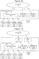
- FIG. 1A is a block diagram of a communication system that is configured to operate according to some embodiments of inventive concepts.
- An example RAN 60 is shown that may be a Long Term Evolution (LTE) RAN.
- Radio base stations (e.g., eNodeBs) 100a are connected directly to one or more core networks 70a.
- functionality of radio network controller(s) (RNC) 100a may be performed by radio base stations 100a.
- Radio base stations 100a communicate over wireless channels 300 with wireless terminals (also referred to as user equipment nodes or UEs) 200a that are within their respective communication service cells (also referred to as coverage areas).
- the radio base stations 100a may be eNodeB's that may communicate with one another through an X2 interface(s) and with the core network(s) 70a through S1 interfaces, as is well known to one who is skilled in the art.
- FIG. 1B is a block diagram of a communication system that is configured to operate according to some other embodiments of present inventive concepts.
- An example RAN 60b is shown that may be a WCDMA RAN.
- Radio base stations (e.g., NodeBs) 100b may be coupled to core network(s) 70b through one or more radio network controllers (RNCs) 65b.
- RNCs radio network controllers
- functionality of a radio network controller(s) may be performed by radio base stations 100b.
- Radio base stations 100b communicate over wireless channels 300b with wireless terminals (also referred to as user equipment nodes or UEs) 200b that are within their respective communication service cells (also referred to as coverage areas).
- the radio base stations 100b can communicate with one another and with the core network(s) 70b, as is well known to one who is skilled in the art.
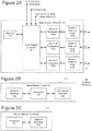
- FIG 2A is a block diagram of a base station 100 (e.g., base station 100a of Figure 1A or base station 100b of Figure 1B ) configured to provide service over three 120 degree sectors (sectors A, B, and C) surrounding the base station according to some embodiments.
- base station 100 includes three transceivers 109a, 109b, and 109c coupled between base station controller 101 and respective sector antenna arrays 117a, 117b, and 117c (each of which includes multiple MIMO antennas), and memory 118 coupled to processor 101.
- each transceiver 109 includes a receiver and a transmitter.
- Each receiver is configured to generate digital data streams corresponding to one or more transport data blocks received through the respective sector antenna array 117 from wireless terminals 200 located in a sector serviced by the respective sector antenna array.
- Each transmitter is configured to transmit one or more transport data blocks through the respective sector antenna array 117 to wireless terminals 200 located in the sector serviced by the sector antenna array responsive to a digital data stream from processor 101.
- base station 100 of Figure 1 defines three 120 degree sectors A, B, and C surrounding the base station, transceiver 109a and sector antenna array 117a support MIMO communications for wireless terminals 200 in sector A of base station 100, transceiver 109b and sector antenna array 117b support MIMO communications for wireless terminals 200 in sector B of base station 100, and transceiver 109c and sector antenna array 117c support MIMO communications for wireless terminals 200 in sector C of base station 100.
- FIG. 2B is a block diagram of base station controller 101 of Figure 2A according to some embodiments.
- base station controller 101 includes processor 141, network interface 143, and transceiver interface 145.
- Network interface 143 provides a communications interface between processor 141 and core network 70, between processor 141 and RNC 121, and/or between processor 141 and other base stations 100.
- Transceiver interface 145 is configured to provide a communications interface between processor 141 and each of transceivers 109a, 109b, and 109c.
- FIG 2C is a block diagram of radio network controller (RNC) 121 of Figure 1B according to some embodiments.
- RCN 121 includes processor 131 and network interface 135.
- Network interface 143 provides a communications interface between processor 131 and base stations 100 and/or between processor 131 and core network 70.
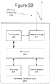
- FIG 2D is a block diagram of a wireless terminal (UE) 200 (e.g., wireless terminal 200a of Figure 1A or wireless terminal 200b of Figure 1B ) according to some embodiments.
- Wireless terminal 200 may be a cellular radiotelephone, a smart phone, a laptop/netbook/tablet/handheld computer, or any other device providing wireless communications.
- Wireless terminal 200 includes processor 201, user interface 211 (e.g., including a visual display such as an liquid crystal display, a touch sensitive visual display, a keypad, a speaker, a microphone, etc.), memory 218, transceiver 209, and sector antenna array 217 (including a plurality of antenna elements).
- transceiver 209 includes a receiver allowing processor 201 to receive data from radio access network 60 over one or more wireless channels 300 through sector antenna array 217 and transceiver 209, and transceiver 209 includes a transmitter allowing processor 201 to transmit data through transceiver 209 and sector antenna array 217 over one or more wireless channels 300 to radio access network 60.
- wireless terminal 200 can receive MIMO communications allowing spatial multiplexing and/or diversity gain as discussed above.
- a maximum number of downlink MIMO channels that can be received simultaneously during multi-flow and/or single-flow MIMO by wireless terminal 200 is equal to the number of antenna elements included in antenna array 217.
- wireless terminal antenna array 217 includes two antenna elements, and wireless terminal 200 is thus limited to receiving no more that 2 MIMO downlink steams simultaneously.
- wireless terminal antenna array 217 may include four antenna elements, and wireless terminal 200 may be limited to receiving no more than 4 MIMO downlink streams simultaneously.
- wireless terminal 200 can receive up to two MIMO downlink data streams simultaneously from a same sector antenna array of RAN.
- wireless terminal antenna array 217 including 4 antenna elements wireless terminal 200 can receive up to four MIMO downlink data streams simultaneously from a same sector antenna array of RAN 60.
- wireless terminal 200 can receive a first MIMO downlink data stream from a first sector antenna array of RAN 60 and a second MIMO downlink data stream from a second sector antenna array of RAN 60 of a same base station or of different base stations.
- wireless terminal 200 can receive first and second MIMO downlink data stream from a first sector antenna array of RAN 60 and third and fourth MIMO downlink data stream from a second sector antenna array of RAN 60; wireless terminal 200 can receive one MIMO downlink data stream from a first sector antenna array of RAN 60 and up to three MIMO downlink data streams from a second sector antenna array of RAN 60; wireless terminal 200 can receive one MIMO downlink data stream from a first sector antenna array of RAN 60 and two MIMO downlink data stream from a second sector antenna array of RAN 60; etc.
- RNC 121 (or processor 131 thereof) can split out different downlink data streams from core network 70 to respective base stations 100 for transmission to wireless terminals 200 in communication with the respective base stations 100.
- the base station controller 101 (or processor 141 thereof) can split out different ones of the downlink data streams for transmission through the transceivers and sector antenna arrays of the respective sectors A, B, and C to wireless terminals 200 communicating through the respective sectors of the base station.
- base station controller 101 (or processor 141 thereof) can combine the different uplink data streams received through the sector antenna arrays of sectors A, B, and C.
- RNC 121 (or processor 135 thereof) can combine the uplink data streams from the different base stations 100, and transmit the combined uplink data streams to core network 70.
- a downlink data stream for a particular wireless terminal 200 can thus include a plurality of transport data blocks provided from core network 70 through radio network controller 121, through base station controller 101 of the base station 100 with which the wireless terminal 200 is communicating, and through the transceiver 109 and sector antenna array 117 for the sector in which the wireless terminal 200 is located.
- processor 131 of RNC 121 directs the downlink transport data block to a respective base station 100
- processor 141 of base station controller 101 directs the downlink transport data block to a respective transceiver and sector antenna array for transmission over the appropriate sector.
- transport data blocks from the same downlink stream can be transmitted from sector antenna arrays of the two different sectors to the wireless terminal to provide increased throughput using multi-flow communications (e.g., using MF-HSDPA).
- processor 141 of base station controller 101 can split the transport data blocks of the downlink data stream to the different transceivers 109 supporting the different sectors to provide intra node aggregation as discussed in greater detail below with respect to Figure 3A .
- processor 131 of RNC 121 can split the transport data blocks of the downlink data stream to the different base stations 100 supporting the different sectors to provide inter node aggregation as discussed in greater detail below with respect to Figure 3B .
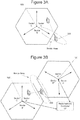
- base station 100 of Figure 2A supports communications with wireless terminals in three different 120 degree sectors A, B, and C. More particularly, transceiver 109a and sector antenna array 117a support MIMO communications with wireless terminals located in Sector A, transceiver 109b and sector antenna array 117b support MIMO communications with wireless terminals located in Sector B, and transceiver 109c and sector antenna array 117c support MIMO communications with wireless terminals located in Sector C. Stated in other words, each of sector antenna arrays 117a, 117b, and 117c (together with respective transceivers 109a, 109b, and 109c) defines a respective 120 degree sector A, B, and C.
- RAN 60 provides wireless communications for a downlink data stream (made up of transport data blocks) by transmitting transport data blocks of the downlink data stream through transceiver 109a and sector antenna array 117a over a wireless channel 300 to wireless terminal 200.
- intra node Multi-Flow communications are be used to transmit different transport data blocks of the downlink data stream in parallel through transceiver 109a and sector antenna array 117a and through transceiver 109b and sector antenna array 117b to wireless terminal 200 (e.g., using MF-HSDPA).
- MF-HSDPA frequency division multiple access
- first and second transport data blocks of the same data stream are respectively transmitted from sector antenna arrays 117a and 117b using a same time/frequency resource element (TFRE) to increase downlink throughput for the wireless terminal in the border area (also referred to as a soft handover region).
- TFRE time/frequency resource element
- a time/frequency resource element may also be referred to as a transmission time interval or TTI.
- first and second transport data blocks are transmitted from sector antenna array 117a and third and fourth transport data blocks are transmitted from sector antenna array 117b using a same TFRE.
- first and second transport data blocks are transmitted from one sector antenna array and a third transport data block is transmitted from the other sector antenna array using a same TFRE.
- processor 141 of base station controller 101 may decide whether to provide Multi-Flow communications for wireless terminal 200.
- the decision to provide Multi-Flow communications may be based on a communication load(s) in sector A and/or sector B.
- two base stations identified as base stations 100' and 100" support communications with wireless terminals, with each of base stations 100' and 100" separately having the structure of Figure 2A (using prime and double prime notation to separately identify elements of the different base stations 100' and 100").
- each base station 100' and 100" is coupled to RNC 121.
- base station 100' supports MIMO communications with wireless terminals located in 120 degree sectors A', B', and C' surrounding base station 100'
- base station 100" supports MIMO communications with wireless terminals located in 120 degree sectors A", B", and C" surrounding base station 100".
- transceiver 109a' and sector antenna array 117a' support MIMO communications with wireless terminals located in Sector A'
- transceiver 109b' and sector antenna array 117b' support MIMO communications with wireless terminals located in Sector B'
- transceiver 109c' and sector antenna array 117c' support MIMO communications with wireless terminals located in Sector C'
- transceiver 109a" and sector antenna array 117a' support MIMO communications with wireless terminals located in Sector A
- transceiver 109b” and sector antenna array 117b” support MIMO communications with wireless terminals located in Sector B
- transceiver 109c" and sector antenna array 117c” support MIMO communications with wireless terminals located in Sector C".
- RAN 60 When wireless terminal 200 is initially located in a central portion of sector A' as shown in Figure 3B , RAN 60 provides wireless communications for a downlink data stream made up of transport data blocks by transmitting the downlink data stream through transceiver 109a' and sector antenna array 117a' over a wireless channel 300 to wireless terminal 200.
- inter node Multi-Flow communications can be used to transmit different transport data blocks of the downlink data stream in parallel through transceiver 109a' and sector antenna array 117a' of base station 100' and through transceiver 109b" and sector antenna array 117b" of base station 100" to wireless terminal 200 (e.g., using MF-HSDPA).
- first and second transport data blocks of the same data stream are respectively transmitted from sector antenna arrays 117a' and 117b" using a same time/frequency resource element (TFRE) to increase downlink throughput for the wireless terminal in the border area (also referred to as a soft handover region).
- TFRE time/frequency resource element
- first and second transport data blocks are transmitted from sector antenna array 117a' and third and fourth transport data blocks are transmitted from sector antenna array 117b" using a same TFRE.
- first and second transport data blocks are transmitted from one sector antenna array and a third transport data block is transmitted from the other sector antenna array using a same TFRE.
- Multi-Flow communications are used to transmit the same transport data block from sector antenna arrays 117a' and 117b" using a same TFRE to provide increased reliability of reception due to diversity gain.
- timing mismatch may occur because schedulers of base stations 100' and 100" act independently and/or because transmission delays between wireless terminal 200 and base stations 100' and 100" are different (due to different distances between wireless terminal 200 and base stations 100' and 100").
- processor 131 of radio network controller 121 decides whether to provide Multi-Flow communications based on a load of sector B".
- processor 131 of radio network controller 121 decides whether to provide Multi-Flow communications based on a load of sector B".
- a load of sector B As discussed, for example, in U.S. Patent Application US 2013/157710 A1 (entitled “Methods Providing Multiflow Communications Based on Sector Loads and Related Network Nodes") to Nammi et al. and filed December 16, 2011, the decision to provide Multi-Flow communications can be based on a communication load in sector A' and/or sector B".
- the primary sector also referred to as a serving cell/sector antenna array (e.g., sector antenna array 117a or 117a') transmits transport data blocks for first data and control channels (e.g., a first high speed shared control channel or HS-SCCH and a first high speed physical downlink shared channel or HS-PDSCH) to wireless terminal 200
- first data and control channels e.g., a first high speed shared control channel or HS-SCCH and a first high speed physical downlink shared channel or HS-PDSCH
- the secondary sector also referred to as an assisting cell/sector antenna array (e.g., sector antenna array 117b or 117b") transmits transport data blocks for second data and control channels (e.g., a second high speed shared control channel or HS-SCCH and a second high speed physical downlink shared channel or HS-PDSCH) to wireless terminal 200.
- wireless terminal 200 transmits a high speed dedicated physical control channel (HS-DPCCH) that is received by both primary and secondary
- a work item on multi-flow (MF) HSDPA High Speed Downlink Packet Access
- MF Multi-flow
- a UE User Equipment, also referred to as a mobile and/or wireless terminal
- TFRE time-frequency-resource-element
- a multi-flow UE can simultaneously receive data from different base station sectors (using a same TFRE) possibly belonging to different base station sites.
- HARQ-ACK Hybrid-Automatic-Repeat-Request-Acknowledge
- HARQ-NACK Hybrid-Automatic-Repeat-Request-Negative-Acknowledge
- MF-HSDPA may be supported for the following configurations: (1) Two sectors/cells without MIMO (multiple-input-multiple-output) configured (SF-DC or Single-Frequency-Dual-Cell, no MIMO); (2) Two sectors/cells with MIMO configured (SF-DC, with MIMO); (3) Four sectors/cells without MIMO configured (DF-QC or Dual-Frequency-Quad-Cell, no MIMO); and (4) Four sectors/cells with MIMO configured (DF-QC, with MIMO).
- MIMO multiple-input-multiple-output
- DC-HSDPA Dual-Carrier-HSDPA
- 4C-HSDPA Four-Carrier-HSDPA
- DC-HSDPA and 4C-HSDPA it was assumed that all cells reside in the same sector/cell and/or base station. This assumption may not necessarily be true in MF-HSDPA, as the cells can belong to different sectors which in turn can belong to different base station (e.g., NodeB and/or eNodeB) sites.
- the different sites e.g., different base stations, NodeBs, eNodeBs, etc.
- the different sites may be unaware of schedules of the other site(s).
- care may need to be taken developing HARQ-ACK/NACK codebooks to be used for multi-flow.
- codebook designs are disclosed for the four supported configurations outlined above, and further codebook designs are disclosed for configurations with two sectors/cells and MIMO configured.
- An issue related to MF-HSDPA is how the HARQ acknowledgment messages should be transmitted in the uplink from one UE to several cells/sectors or base stations (NodeBs). According to some embodiments, this information is carried on the HS-DPCCH.
- the HS-DPCCH carries downlink related feedback information when HSDPA (High Speed Downlink Packet Access) is configured.
- This feedback information can include and/or consist of: HARQ-ACK messages whereby the UE can indicate whether the reception of packet(s) scheduled on the downlink was successful; and CQI whereby the UE informs the NodeB scheduler about the maximum transport data block size that it could receive with a 10 percent block error ratio (BLER).
- BLER block error ratio
- Figure 4 illustrates a structure of an HS-DPCCH sub-frame slot format according to some embodiments.
- the HARQ-ACK message is transmitted during the first slot (including 10 bits), and the encoded CQI information/message is transmitted during the last 2 slots of the sub-frame (including 20 bits).
- a design principle for MF-HSDPA HARQ-ACK codebooks may be to re-use existing multicarrier alternatives/codebooks.
- a difference between multicarrier operation and inter-cell (also referred to as inter-NodeB) MF-HSDPA is that for inter-cell MF-HSDPA configurations, each site may be unaware of schedules of other sites transmitting to the same UE using a same TFRE (e.g., the number of streams scheduled by the other site or sites).
- multicarrier codebook design makes use of knowledge of a number of streams that are scheduled during a decoding process. Accordingly, directly applying multicarrier codebooks for MF-HSDPA may be difficult in some scenarios.
- Some embodiments of inventive concepts may address HARQ-ACK designs for MF-HSDPA configurations with two cells/sectors and MIMO, a scenario where it can be difficult to directly re-use multicarrier codebooks due to issues noted above.
- an SF256 spreading factor 256, i.e. the HS-DPCCH may use a channelization code with spreading factor of 256
- HARQ-ACK codebook solution is provided for MF-HSDPA with two cells and MIMO configured.
- a maximum of four streams may need to be acknowledged (i.e. one acknowledgment message for each stream and sector/cell).
- Three different HARQ-ACK messages are possible for each stream; ACK(A) or acknowledge, NACK(N) or negative acknowledge, and DTX(D) or discontinuous transmission.
- Each site e.g., each base station, NodeB, eNodeB, etc.
- Each base station or NodeB can use knowledge about the number of its own scheduled streams in the decoding process, but each base station and/or NodeB may be unaware of the number of streams scheduled by the other base station and/or NodeB in an inter-cell configuration.
- Two solutions for the HARQ-ACK design are to: (1) use an SF128 solution similar to multicarrier Rel-10 where each site is coded independently using the Rel-8 codebook; and/or (2) use an SF256 solution similar to multicarrier Rel-9.
- Use of an SF256 solution may be desired because an SF256 solution may be more in line with the multicarrier evolution and, in general, an SF256 solution may provide improved performance relative to an SF128 solution.
- a difference between MF-HSDPA and Rel-9 multicarrier is that, for inter-cell MF-HSDPA, each site and/or base station may be unaware of scheduling at the other base station and/or site transmitting to the same UE using a same TFRE. Accordingly, re-use of the Rel-9 multicarrier HARQ-ACK codebook directly for MF-HSDPA may be difficult, and a new codebook may need to be designed.
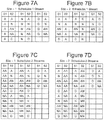
- Figures 5A, 5B, 5C, and 5D provide tables showing different codeword combinations used in a decoding process for different scheduling options according to some embodiments of inventive concepts.
- S1 denotes site 1
- S2 denotes site 2
- X/X represents single stream transmission from both cells/sectors A' and B" (e.g., from both radio base stations 100' and 100" for sectors/cells A' and B")
- XX/X represents dual stream transmission from cell/sector A' (e.g., from radio base station 100' for sector/cell A') and single stream transmission from cell/sector B" (e.g., from radio base station 100" for sector/cell B"
- X/XX represents single stream transmission from cell/sector A' (e.g., from radio base station 100' for sector/cell A') and dual stream transmission from cell/sector B" (e.g., from radio base station 100"
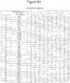
- FIG. 6A and 6B An example of a HARQ-ACK codebook according to some embodiments of inventive concepts is given in the table of Figures 6A and 6B , and the codebook of Figures 6A and 6B can be saved in memory 218 of each wireless terminal 200 and in memory 118 of each base station 100.
- A represents an ACK
- N represents a NACK
- D represents a DTX.
- Design principles for the codebook of Figures 6A and 6B may include:
- X/X represents single stream transmission from both cells/sectors A' and B" (e.g., from both radio base stations 100' and 100" for sectors/cells A' and B");
- XX/X represents dual stream transmission from cell/sector A' (e.g., from radio base station 100' for sector/cell A') and single stream transmission from cell/sector B" (e.g., from radio base station 100" for sector/cell B");
- X/XX represents single stream transmission from cell/sector A' (e.g., from radio base station 100' for sector/cell A') and dual stream transmission from cell/sector B" (e.g., from radio base station 100" for cell/sector B”);
- XX/XX represents dual stream transmission from both cells/sectors A' and B" (e.g.
- codebooks can be considered that can be obtained through these operations starting from a proposed codebook according to embodiments of inventive concepts. Such operations, however, may change individual distance properties between different codewords.
- HARQ-ACK information for MF-HSDPA configured with two cells and MIMO may be acknowledged using a SF256 approach.
- operations of Figure 9 may be performed simultaneously for two different sectors/cells of the same or different base stations (e.g., sectors/cells A and B of Figure 3A , or sectors/cells A' and B" of Figure 3B ).
- sectors/cells A and B of Figure 3A e.g., sectors/cells A and B of Figure 3A , or sectors/cells A' and B" of Figure 3B .
- operations of Figure 9 will be discussed with respect to base station operations for a primary sector/cell A or A' for ease of discussion, and it will be understood that operations of Figure 9 may be performed simultaneously for a secondary sector/cell B or B" at the same or different base stations.
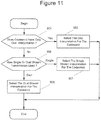
- base station controller 101 may determine at block 701 that the time has arrived for a next downlink (DL) transmission to wireless terminal 200, and at block 703, base station controller 101 may select either single stream (transmitting only a single transport data block) or dual stream (transmitting two transport data blocks simultaneously) for transmission from primary cell/sector A or A' to wireless terminal 200 during a current time resource element (also referred to as a transmission time interval or TTI).
- a current time resource element also referred to as a transmission time interval or TTI.
- the same or adjacent base station for the secondary cell/sector B or B" may also separately select single or dual stream transmission for transmission from secondary cell/sector B or B" during the same time resource element.
- Primary base station controller 101 may then transmit (through sector transceiver 109a or 109a' and sector antenna array 117a or 117a') either one transport data block to wireless terminal 200 for the current time resource element at block 707 for single stream transmission, or two transport data blocks to wireless terminal 200 for the current time resource element at block 709 for dual stream transmission.
- Secondary base station controller 101 may similarly transmit (through sector transceiver 109b or 109b" and sector antenna array 117b or 117b") either one transport data block to wireless terminal 200 for the current time resource element at block 707 for single stream transmission, or two transport data blocks to wireless terminal 200 for the current time resource element at block 709 for dual stream transmission.
- wireless terminal processor 201 may receive transport data blocks from primary and secondary cells/sectors at block 803 (through antenna array 217 and transceiver array 209).
- wireless terminal 200 may simultaneously receive one transport data block from the primary cell/sector and one transport data block from the secondary cell/sector, one transport data block from the primary cell/sector and two transport data blocks from the secondary cell/sector, two transport data blocks from the primary cell/sector and one transport data block from the secondary cell/sector, or two transport data blocks from the primary cell/sector and two transport data blocks from the secondary cell/sector.
- the base station controllers of the primary and secondary cells/sectors may be unaware of the number of transport data blocks transmitted by the other cell/sector during the current time resource element if the primary and secondary cells/sectors belong to different base stations.
- wireless terminal processor 201 prepares a feedback message for the downlink transmission based on the transport data block(s) received simultaneously from the primary and secondary cells/sectors during the current time resource element. More particularly, the feedback message can include a codeword from the HARQ-ACK codebook of Figures 6A and 6B (or from the HARQ-ACK codebook of Figure 8 ) discussed above, wherein the codeword provides acknowledgement information for each transport data block received during the current time resource element. As discussed above, some codewords may have different interpretations, and the correct one of the different interpretations may be selected at the base station(s) for each transport data block transmitted from the respective cell/sector based on whether single or dual stream transmission was selected for the respective cell/sector.
- the feedback message can be prepared according to a HS-DPCCH format (of Figure 4 ) with a 10 bit codeword (e.g., selected from the codebook of Figures 6A and 6B or selected from the codebook of Figure 8 ) and with 20 bits of CQI information.
- the feedback message is transmitted by wireless terminal processor 201 through transceiver 209 and antenna array 217 over wireless channel(s) 300 to the primary cell/sector A or A' and the secondary cell/sector B or B". More particularly, the same feedback message is transmitted according to an HS-DPCCH format to both primary and secondary cells/sectors.
- the respective base station controller(s) Upon receiving the feedback message at block 711 at the primary and secondary cells/sectors, the respective base station controller(s) proceeds to interpret the codeword of the feedback message for each transport data block transmitted from each cell/sector for the time resource element at block 715 based on whether a single or dual stream transmission was provided from the respective cell/sector for the time resource element and based on the status of the respective cell/sector as the primary or secondary cell/sector for the multi-flow downlink transmission.
- base station controller(s) 101 for the primary cell/sector A or A' and for secondary cell/sector B and B" interprets the codeword "0010100001" (codebook entries 13 and 33) as an acknowledgement for one transport data block when a single stream transmission was provided, and as an acknowledgement for two transport data blocks when a dual stream transmission was provided.
- the codebook of Figure 8 can be used in a similar way.
- base station controller 101 for the primary cell/sector A or A' interprets the codeword "0111000110" (codebook entries 14 and 44) as an acknowledgement for one transport data block when a single stream transmission was provided, and as a negative acknowledgement for a first transport data block and an acknowledgement for a second transport data block when a dual stream transmission was provided.
- base station controller 101 for the secondary cell/sector B or B may interpret the same codeword "0111000110" (codebook entries 14 and 44) as a negative acknowledgement for one transport data block when a single stream transmission was provided from the secondary cell/sector, and as a negative acknowledgement for both transport data blocks when a dual stream transmission was provided.
- codebook entries 13 and 33 Different interpretations of the codewords "0010100001" (codebook entries 13 and 33), “0111000110” (codebook entries 14 and 44), “1000111111” (codebook entries 15 and 43), and “1101001010” (codebook entries 16 and 35) may be determined as discussed above with respect to codebook entries 13, 14, 15, 16, 33, 35, 43, and 44 of Figures 6A and 6B .
- codebook entries 1-2, 5-6, and 9-20 from the codebook of Figure 8 may have different interpretations for the primary sector and/or for the secondary sector depending on the number of transport data blocks that were transmitted by the respective sector during the respective time resource element.
- codebook entries may have only one interpretation for the primary sector and only one interpretation for the secondary sector.
- the base station controller(s) 101 for the primary and secondary cells/sectors may determine if retransmission of one or more of the transport data blocks is required responsive to the codeword received with the feedback message. If retransmission is required at block 717, the appropriate transport data block(s) may be re-queued for retransmission at block 719.
- base station controller(s) 101 may wait for a next time resource element for transmission to wireless terminal before repeating operations of Figure 9 for a next multi-flow transmission to wireless terminal 200.
- base station controller 101 may determine if the codeword has only one interpretation or if two different interpretations are possible. If the codeword has only one interpretation for the respective cell/sector, then base station processor 101 selects the one interpretation for the codeword at block 903 and proceeds to block 717 using the only available interpretation of the codeword.
- each of codebook entries 1-12, 17-32, 34, 36-42, and 45-48 is assigned a unique codeword so that further interpretation is not required.
- each of codebook entries 3-4, 7-8, and 21-24 has only a single interpretation for the primary cell/sector and only a single interpretation for the secondary cell/sector.
- base station processor 101 determines if the codeword corresponds to a single or dual stream transmission for that base station cell/sector at block 905.
- codeword 1 st Interpretation Single Stream
- 2 nd Interpretation Double Stream
- 0010100001 A/A Entry 13
- AA/AA Entry 33
- 0111000110 A/N Entry 14
- NA/NN Entry 44
- 1000111111 N/A Entry 15
- NA/NA Entry 43
- 110100101010 N/N Entry 16
- AA/NA Entry 35
- sixteen codewords for codebook entries 1-2, 5-6, and 9-20 of Figure 8 ) have at least two possible interpretation
- an acknowledge is interpreted for the transport data block transmitted from the primary sector (A or A') and for the transport data block transmitted from the secondary sector (B or B") as shown by codebook entry 13.
- an acknowledge is interpreted for both transport data blocks transmitted from the primary sector (A or A') and for both transport data blocks transmitted from the secondary sector (B or B") as shown by codebook entry 33.
- an acknowledge (A or ACK) is interpreted for the transport data block transmitted from the primary sector (A or A') and a negative acknowledge (N or NACK) is interpreted for the transport data block transmitted from the secondary sector (B or B") as shown by codebook entry 14.
- N or NACK negative acknowledge
- a or ACK acknowledge
- N or NACK negative acknowledge
- N or NACK negative acknowledge
- a or ACK acknowledge
- a negative acknowledge is interpreted for a first transport data block transmitted from the primary sector (A or A')
- an acknowledge is interpreted for a second transport data block transmitted from the primary sector (A or A')
- a negative acknowledge is interpreted for a first transport data block transmitted from the secondary sector (B or B)
- an acknowledge is interpreted for a second transport data block transmitted from the secondary sector (B or B) as shown by codebook entry 43.
- NACK negative acknowledge
- an acknowledge is interpreted for both transport data blocks transmitted from the primary sector (A or A')
- a negative acknowledge is interpreted for a first transport data block transmitted from the secondary sector (B or B)
- an acknowledge is interpreted for a second transport data block transmitted from the secondary sector (B or B) as shown by codebook entry 35.
- the codebook of Figure 8 can be used in a similar way to that described above with respect to the codebook of Figures 6A and 6B .
- codeword "0001101101" entity 11 of the codebook of Figure 8
- a negative acknowledge (N or NACK) is interpreted for the transport data block from the primary sector (A or A') and an acknowledge (A or ACK) is interpreted for the transport data block transmitted from the secondary sector (B or B").
- a negative acknowledge (N or NACK) is interpreted for both transport data blocks from the primary sector (A or A') and an acknowledge (A or ACK) is interpreted for both transport data blocks transmitted from the secondary sector (B or B").
- N or NACK negative acknowledge
- a or ACK acknowledge
- N or NACK negative acknowledge
- a or ACK acknowledge
- the base station controller(s) for the primary sector A/A' and the secondary sector B/B" may determine at block 701 that the time has arrived for a next downlink (DL) multi-flow transmission to wireless terminal 200, and at block 703, the base station controller(s) may select single stream transmission for each of the primary and secondary sectors A/A' and B/B". According to some embodiments, only single stream transmission from each of the primary and secondary sectors may be supported for multi-flow downlink transmission to reduce a processing burden at the receiving wireless terminal 200.
- a first downlink stream may be transmitted from primary sector A/A' and a second downlink stream may be transmitted for secondary sector B/B" so that wireless terminal 200 receives only the first downlink stream from the primary cell/sector and the second downlink stream from the secondary cell/sector.
- the base station controller(s) may transmit a first transport data block from primary sector A/A' of the network and a second transport data block from secondary sector B/B" over a downlink during a time resource element for the multi-flow downlink transmission to wireless terminal 200 at block 707.
- wireless terminal processor 201 may receive the first and second transport data blocks from the respective primary and secondary sectors A/A' and B/B" at block 803 (through antenna array 217 and transceiver array 209). At block 805, wireless terminal processor 201 prepares a feedback message based on the first and second transport data blocks received simultaneously from the primary secondary cells/sectors during the current time resource element.
- the feedback message may be prepared using codewords selected from codebook entries 1-2, 5-6, and 9-12 of Figure 8 (i.e., using a reduced HARQ-ACK codebook) as set forth in the table of Figure 12 .
- the codeword "1110000101” is thus interpreted as ACK for the single transport data block transmitted from primary sector A/A' and as Discontinuous Transmission DTX for the single transport data block transmitted from secondary sector B/B".
- the codeword "1100101001” is interpreted as NACK for the single transport data block transmitted from primary sector A/A' and as Discontinuous Transmission DTX for the single transport data block transmitted from the secondary sector B/B".
- the codeword "0111101011” is interpreted as Discontinuous Transmission DTX for the single transport data block transmitted from primary sector A/A' and as ACK for the single transport data block transmitted from secondary sector B/B".
- the codeword "0010100001” is interpreted as Discontinuous Transmission DTX for the single transport data block transmitted from primary sector A/A' and as NACK for the single transport data block transmitted from secondary sector B/B".
- the codeword "1001010110” is interpreted as ACK for the single transport data block transmitted from primary sector A/A' and as ACK for the single transport data block transmitted from secondary sector B/B”.
- the codeword "1010011001” is interpreted as ACK for the single transport data block transmitted from primary sector A/A' and as NACK for the single transport data block transmitted from secondary sector B/B".
- the codeword "0001101101” is interpreted as NACK for the single transport data block transmitted from primary sector A/A' and as ACK for the single transport data block transmitted from secondary sector B/B".
- the codeword "0111110000” is interpreted as NACK for the single transport data block transmitted from primary sector A/A' and as NACK for the single transport data block transmitted from secondary sector B/B".
- some codewords can have different interpretations, and the correct one of the different interpretations may be selected at the base station(s) for each transport data block transmitted from the respective cell/sector based on whether the respective cell/sector is the primary cell/sector for the multi-flow downlink transmission or the secondary cell/sector for the multi-flow downlink transmission.
- the feedback message can be prepared according to a HS-DPCCH format (of Figure 4 ) using the 10 bit codewords noted above.
- the feedback message is transmitted by wireless terminal processor 201 through transceiver 209 and antenna array 217 over wireless channel(s) 300 to primary cell/sector A/A' and secondary cell/sector B/B". More particularly, the same feedback message is transmitted according to an HS-DPCCH format to both primary and secondary cells/sectors.
- the respective base station controller(s) Upon receiving the feedback message at primary cell/sector A/A' and secondary cell/sector B/B" at block 711, the respective base station controller(s) proceeds to interpret the codeword of the feedback message for each transport data block transmitted from each cell/sector for the time resource element at block 715 based on whether the respective transport data block was transmitted from the primary or secondary cell/sector.
- the HARQ-ACK codeword "1010011001" is interpreted as an ACK for the transport data block transmitted from primary cell/sector A/A', and as a NACK for the transport data block transmitted from the secondary cell/sector B/B".
- the HARQ-ACK codeword "0001101101” is interpreted as an NACK for the transport data block transmitted from primary cell/sector A/A', and as a ACK for the transport data block transmitted from the secondary cell/sector B/B".
- the HARQ-ACK codeword "1110000101” is interpreted as an ACK for the transport data block transmitted from primary cell/sector A/A', and as a Discontinuous Transmission DTX for the transport data block transmitted from the secondary cell/sector B/B".
- the HARQ-ACK codeword "1100101001” is interpreted as an NACK for the transport data block transmitted from primary cell/sector A/A', and as a Discontinuous Transmission DTX for the transport data block transmitted from the secondary cell/sector B/B".
- the HARQ-ACK codeword "0111101011” is interpreted as an Discontinuous Transmission DTX for the transport data block transmitted from primary cell/sector A/A', and as an ACK for the transport data block transmitted from the secondary cell/sector B/B".
- the HARQ-ACK codeword "0010100001" is interpreted as a Discontinuous Transmission DTX for the transport data block transmitted from primary cell/sector A/A', and as a NACK for the transport data block transmitted from the secondary cell/sector B/B".
- the base station controller(s) 101 for the primary cell/sector A/A' and for the secondary cell/sector B/B" may determine if retransmission of the first transport data block transmitted from primary cell/sector A/A' or the second transport data block transmitted from the secondary cell/sector B/B" is required responsive to the codeword received with the feedback message. If retransmission is required for either of the first and/or second transport data blocks at block 717, the appropriate transport data block(s) may be re-queued for retransmission at block 719.
- base station controller(s) 101 may wait for a next time resource element for transmission to wireless terminal before repeating operations of Figure 9 for a next multi-flow transmission to wireless terminal 200.
- Operations of Figures 9 and 10 discussed above with respect to the reduced codebook of Figure 12 may be performed for intra-node multi-flow transmissions when primary and secondary cells/sectors A and B are provided at a same base station 100, and/or for inter-node multi-flow transmission when primary and secondary cells/sectors A' and B" are provided at different and spaced apart base stations 100' and 100".
- the codebook of Figures 6A and 6B , the codebook of Figure 8 , and the reduced codebook of Figure 12 are examples of different embodiments of codebooks that may be used according to different embodiments of inventive concepts. Embodiments of inventive concepts, however, are not limited to these codebooks, and other codebooks may be used according to other embodiments of inventive concepts.
- the terms “comprise”, “comprising”, “comprises”, “include”, “including”, “includes”, “have”, “has”, “having”, or variants thereof are open-ended, and include one or more stated features, integers, elements, steps, components or functions but do not preclude the presence or addition of one or more other features, integers, elements, steps, components, functions or groups thereof.
- the common abbreviation “e.g.” which derives from the Latin phrase “exempli gratia,” may be used to introduce or specify a general example or examples of a previously mentioned item, and is not intended to be limiting of such item.
- the common abbreviation “i.e.”, which derives from the Latin phrase “id est,” may be used to specify a particular item from a more general recitation.
- Example embodiments are described herein with reference to block diagrams and/or flowchart illustrations of computer-implemented methods, apparatus (systems and/or devices) and/or computer program products. It is understood that a block of the block diagrams and/or flowchart illustrations, and combinations of blocks in the block diagrams and/or flowchart illustrations, can be implemented by computer program instructions that are performed by one or more computer circuits.
- These computer program instructions can be provided to a processor circuit of a general purpose computer circuit, special purpose computer circuit, and/or other programmable data processing circuit to produce a machine, such that the instructions, which execute via the processor of the computer and/or other programmable data processing apparatus, transform and control transistors, values stored in memory locations, and other hardware components within such circuitry to implement the functions/acts specified in the block diagrams and/or flowchart block or blocks, and thereby create means (functionality) and/or structure for implementing the functions/acts specified in the block diagrams and/or flowchart block(s).
- These computer program instructions may also be stored in a tangible computer-readable medium that can direct a computer or other programmable data processing apparatus to function in a particular manner, such that the instructions stored in the computer-readable medium produce an article of manufacture including instructions which implement the functions/acts specified in the block diagrams and/or flowchart block or blocks.
- a tangible, non-transitory computer-readable medium may include an electronic, magnetic, optical, electromagnetic, or semiconductor data storage system, apparatus, or device. More specific examples of the computer-readable medium would include the following: a portable computer diskette, a random access memory (RAM) circuit, a read-only memory (ROM) circuit, an erasable programmable read-only memory (EPROM or Flash memory) circuit, a portable compact disc read-only memory (CD-ROM), and a portable digital video disc read-only memory (DVD/BlueRay).
- RAM random access memory
- ROM read-only memory
- EPROM or Flash memory erasable programmable read-only memory
- CD-ROM compact disc read-only memory
- DVD/BlueRay portable digital video disc read-only memory
- the computer program instructions may also be loaded onto a computer and/or other programmable data processing apparatus to cause a series of operational steps to be performed on the computer and/or other programmable apparatus to produce a computer-implemented process such that the instructions which execute on the computer or other programmable apparatus provide steps for implementing the functions/acts specified in the block diagrams and/or flowchart block or blocks.
- inventive concepts may be embodied in hardware and/or in software (including firmware, resident software, micro-code, etc.) that runs on a processor such as a digital signal processor, which may collectively be referred to as "circuitry," "a module” or variants thereof.
Description
- The present disclosure is directed to wireless communications and, more particularly, to Multi-Flow (MF) wireless communications and related network nodes and wireless terminals.
- In a typical cellular radio system, wireless terminals (also referred to as user equipment unit nodes, UEs, and/or mobile stations) communicate via a radio access network (RAN) with one or more core networks. The RAN covers a geographical area which is divided into cell areas, with each cell area being served by a radio base station (also referred to as a RAN node, a "NodeB", and/or enhanced NodeB "eNodeB"). A cell area is a geographical area where radio coverage is provided by the base station equipment at a base station site. The base stations communicate through radio communication channels with UEs within range of the base stations.
- Moreover, a cell area for a base station may be divided into a plurality of sectors surrounding the base station. For example, a base station may service three 120 degree sectors surrounding the base station, when the base station providing a respective directional transceiver and sector antenna array for each sector. Stated in other words, a base station may include three directional sector antenna arrays servicing respective 120 degree base station sectors surrounding the base station.
- Multi-antenna techniques can significantly increase capacity, data rates, and/or reliability of a wireless communication system as discussed, for example, by Telatar in "Capacity Of Multi-Antenna Gaussian Channels" (European Transactions On Telecommunications, Vol. 10, pp. 585-595, Nov. 1999). Performance can be improved if both the transmitter and the receiver for a base station sector are equipped with multiple antennas (e.g., an sector antenna array) to provide a multiple-input multiple-output (MIMO) communication channel(s) for the base station sector. Such systems and/or related techniques are commonly referred to as MIMO (Multiple-Input-Multiple-Output). The HSPA (High Speed Packet Access) standard is currently evolving with enhanced MIMO support and MIMO antenna deployments. A spatial multiplexing mode is provided for relatively high data rates in more favorable channel conditions, and a transmit diversity mode is provided for relatively high reliability (at lower data rates) in less favorable channel conditions.
- In a downlink (DL) from a base station transmitting from a sector antenna array over a MIMO channel to a wireless terminal in the sector, for example, spatial multiplexing (or SM) allows the simultaneous transmission of multiple symbol streams over the same frequency from the base station sector antenna array for the sector. Stated in other words, multiple symbol streams are transmitted from the base station sector antenna array for the sector to the wireless terminal over the same downlink time/frequency resource element (TFRE) to provide an increased data rate. As used herein, a time/frequency resource element may also be referred to as a transmission time interval or TTI. In a downlink from the same base station sector transmitting from the same sector antenna array to the same wireless terminal, transmit diversity (e.g., using space-time codes) is the simultaneous transmission of the same symbol stream over the same frequency from different antennas of the base station sector antenna array. Stated in other words, the same symbol stream is transmitted from different antennas of the base station sector antenna array to the wireless terminal over the same time/frequency resource element (TFRE) to provide increased reliability of reception at the wireless terminal due to transmit diversity gain.
- To further increase throughput at a sector/cell edge (also referred to as a soft handover or border area) using High Speed Downlink Packet Access (HSDPA), Multi-Flow-HSDPA (MF-HSDPA, also referred to as Multi-Flow-HSDPA or MP-HSDPA) has been proposed for 3rd Generation Partnership Project (3GPP) communications. In MF-HSDPA, transport data blocks of a data stream are transmitted from two different sectors/cells of the same or different base stations to a same wireless terminal in a border area between the sectors/cells. Intra NodeB aggregation (also referred to as intra node Multi-Flow communications) occurs when different transport data blocks of a data stream are transmitted from two different sectors of a same base station to a wireless terminal, and Inter NodeB aggregation (also referred to as inter node Multi-Flow communications) occurs when different transport data blocks of a data stream are transmitted from sectors/cells of different base stations to a wireless terminal. MF-HSDPA may thus provide advantages of parallel data streams like MIMO where the spatially separated antennas are taken from different sectors/cells.
- When MF-HSDPA is used to transmit transport data blocks from different base stations to a wireless terminal during a same time resource element (also referred to as a transmission time interval or TTI), neither base station may be aware of how many transport data blocks were transmitted by the other base station. Accordingly, it may be difficult to provide efficient feedback from the wireless terminal to the network regarding the transport data blocks of a multi-flow transmission.
- 3rd Generation Partnership Project (3GPP); R1-114174, Uplink control channel structure and timing, HSDPA Multiflow Data; XP050562130, 2011-11-08, describe a multi-flow HSDPA transmission, with inter-site multi-flow transmission where cells (sectors) resides in different NodeBs.
- 3rd Generation Partnership Project (3GPP); TSG-RAN WG1 Meeting #66; R1112875; 25.212 CR 0296 Introduction of 8C-HSDPA, 2011-08-22, (http://www.3gpp.org/ftp/tsg_ran/wg1_r11/TSGR1_66/Docs/), describe various combinations of enabled/not enabled primary and secondary cell transmissions, with or without MIMO enabled.
- It may therefore be an object to address at least some of the above mentioned disadvantages and/or to improve performance in a wireless communication system.
- The invention is defined by
independent claims - The accompanying drawings, which are included to provide a further understanding of the disclosure and are incorporated in and constitute a part of this application, illustrate certain non-limiting embodiment(s) of inventive concepts. In the drawings:
-
Figures 1A and 1B are block diagrams of communications systems that are configured according to some embodiments; -
Figures 2A, 2B, 2C , and2D are block diagrams respectively illustrating a base station, a base station controller, a radio network controller, and a wireless terminal according to some embodiments ofFigures 1A and/or 1B; -
Figures 3A and 3B are schematic diagrams respectively illustrating intra node and inter node Multi-Flow communications according to some embodiments; -
Figure 4 is a block diagram illustrating an HS-DPCCH slot format including 3 slots with 10 bits per slot; -
Figures 5A, 5B, 5C, and 5D are tables illustrating codewords for HARQ-ACK/NACK/DTX reporting according to some embodiments; -
Figures 6A and6B together provide a table illustrating a codebook of codewords for HARQ-ACK/NACK/DTX reporting according to some embodiments; -
Figure 7 is a table illustrating codewords for HARQ-ACK/NACK/DTX reporting according to some other embodiments; -
Figure 8 is a table illustrating a codebook of codewords for HARQ-ACK/NACK/DTX reporting according to some other embodiments; -
Figure 9 is a flow diagram illustrating base station operations according to some embodiments; -
Figure 10 is a flow diagram illustrating wireless terminal operations according to some embodiments; -
Figure 11 is a flow diagram illustrating base station operations to interpret codewords according to some embodiments; and -
Figure 12 is a table illustrating a reduced codebook based on codebook entries 1-2, 5-6, and 9-12 ofFigure 8 according to some embodiments. - Embodiments of inventive concepts will now be described more fully hereinafter with reference to the accompanying drawings, in which examples of embodiments of inventive concepts are shown. Inventive concepts may, however, be embodied in many different forms and should not be construed as limited to the embodiments set forth herein. Rather, these embodiments are provided so that this disclosure will be thorough and complete, and will fully convey the scope of the present inventive concepts to those skilled in the art. It should also be noted that these embodiments are not mutually exclusive. Components from one embodiment may be tacitly assumed to be present/used in another embodiment.
- For purposes of illustration and explanation only, these and other embodiments of the inventive concepts are described herein in the context of operating in a RAN that communicates over radio communication channels with wireless terminals (also referred to as UEs). It will be understood, however, that the present inventive concepts are not limited to such embodiments and may be embodied generally in any type of communication network. As used herein, a wireless terminal (also referred to as a UE) can include any device that receives data from a communication network, and may include, but is not limited to, a mobile telephone ("cellular" telephone), laptop/portable computer, pocket computer, hand-held computer, and/or desktop computer.
- In some embodiments of a RAN, several base stations can be connected (e.g., by landlines or radio channels) to a radio network controller (RNC). The radio network controller, also sometimes termed a base station controller (BSC), supervises and coordinates various activities of the plural base stations connected thereto. The radio network controller is typically connected to one or more core networks.
- The Universal Mobile Telecommunications System (UMTS) is a third generation mobile communication system, which evolved from the Global System for Mobile Communications (GSM), and is intended to provide improved mobile communication services based on Wideband Code Division Multiple Access (WCDMA) technology. UTRAN, short for UMTS Terrestrial Radio Access Network, is a collective term for the NodeB's and Radio Network Controllers which make up the UMTS radio access network. Thus, UTRAN is essentially a radio access network using wideband code division multiple access for UEs.
- The Third Generation Partnership Project (3GPP) has undertaken to further evolve the UTRAN and GSM based radio access network technologies. In this regard, specifications for the Evolved Universal Terrestrial Radio Access Network (E-UTRAN) are ongoing within 3GPP. The Evolved Universal Terrestrial Radio Access Network (E-UTRAN) comprises the Long Term Evolution (LTE) and System Architecture Evolution (SAE).
- Note that although terminology from HSDPA (High-Speed Downlink Packet Access) and/or WCDMA (Wideband Code Division Multiple Access) is used in this disclosure to exemplify embodiments of inventive concepts, this should not be seen as limiting the scope of inventive concepts to only these systems. Other wireless systems, including WiMax (Worldwide Interoperability for Microwave Access), UMB (Ultra Mobile Broadband), 3GPP (3rd Generation Partnership Project) LTE (Long Term Evolution), GSM (Global System for Mobile Communications), etc., may also benefit from exploiting embodiments of inventive concepts disclosed herein.
- Also note that terminology such as base station (e.g., a NodeB and/or eNodeB) and wireless terminal (also referred to as UE or User Equipment) should be considering non-limiting and does not imply a certain hierarchical relation between the two. In general a base station (e.g., a NodeB and/or eNodeB) and a wireless terminal (e.g., a "UE") may be considered as examples of respective different communications devices that communicate with each other over a wireless radio channel. While embodiments discussed herein may focus on wireless transmissions in a downlink from an NodeB/eNodeB to a UE, embodiments of inventive concepts may also be applied, for example, in the uplink.
-
Figure 1A is a block diagram of a communication system that is configured to operate according to some embodiments of inventive concepts. An example RAN 60 is shown that may be a Long Term Evolution (LTE) RAN. Radio base stations (e.g., eNodeBs) 100a are connected directly to one ormore core networks 70a. In some embodiments, functionality of radio network controller(s) (RNC) 100a may be performed byradio base stations 100a.Radio base stations 100a communicate overwireless channels 300 with wireless terminals (also referred to as user equipment nodes or UEs) 200a that are within their respective communication service cells (also referred to as coverage areas). Theradio base stations 100a may be eNodeB's that may communicate with one another through an X2 interface(s) and with the core network(s) 70a through S1 interfaces, as is well known to one who is skilled in the art. -
Figure 1B is a block diagram of a communication system that is configured to operate according to some other embodiments of present inventive concepts. Anexample RAN 60b is shown that may be a WCDMA RAN. Radio base stations (e.g., NodeBs) 100b may be coupled to core network(s) 70b through one or more radio network controllers (RNCs) 65b. In some embodiments, functionality of a radio network controller(s) may be performed byradio base stations 100b.Radio base stations 100b communicate overwireless channels 300b with wireless terminals (also referred to as user equipment nodes or UEs) 200b that are within their respective communication service cells (also referred to as coverage areas). Theradio base stations 100b can communicate with one another and with the core network(s) 70b, as is well known to one who is skilled in the art. -
Figure 2A is a block diagram of a base station 100 (e.g.,base station 100a ofFigure 1A orbase station 100b ofFigure 1B ) configured to provide service over three 120 degree sectors (sectors A, B, and C) surrounding the base station according to some embodiments. As shown, for example,base station 100 includes threetransceivers base station controller 101 and respectivesector antenna arrays 117a, 117b, and 117c (each of which includes multiple MIMO antennas), andmemory 118 coupled toprocessor 101. - More particularly, each transceiver 109 includes a receiver and a transmitter. Each receiver is configured to generate digital data streams corresponding to one or more transport data blocks received through the respective sector antenna array 117 from
wireless terminals 200 located in a sector serviced by the respective sector antenna array. Each transmitter is configured to transmit one or more transport data blocks through the respective sector antenna array 117 towireless terminals 200 located in the sector serviced by the sector antenna array responsive to a digital data stream fromprocessor 101. For example,base station 100 ofFigure 1 defines three 120 degree sectors A, B, and C surrounding the base station,transceiver 109a andsector antenna array 117a support MIMO communications forwireless terminals 200 in sector A ofbase station 100,transceiver 109b and sector antenna array 117b support MIMO communications forwireless terminals 200 in sector B ofbase station 100, andtransceiver 109c and sector antenna array 117c support MIMO communications forwireless terminals 200 in sector C ofbase station 100. -
Figure 2B is a block diagram ofbase station controller 101 ofFigure 2A according to some embodiments. As shown, for example,base station controller 101 includesprocessor 141,network interface 143, andtransceiver interface 145.Network interface 143 provides a communications interface betweenprocessor 141 and core network 70, betweenprocessor 141 andRNC 121, and/or betweenprocessor 141 andother base stations 100.Transceiver interface 145 is configured to provide a communications interface betweenprocessor 141 and each of transceivers 109a, 109b, and 109c. -
Figure 2C is a block diagram of radio network controller (RNC) 121 ofFigure 1B according to some embodiments. As shown, for example,RCN 121 includesprocessor 131 andnetwork interface 135.Network interface 143 provides a communications interface betweenprocessor 131 andbase stations 100 and/or betweenprocessor 131 and core network 70. -
Figure 2D is a block diagram of a wireless terminal (UE) 200 (e.g.,wireless terminal 200a ofFigure 1A orwireless terminal 200b ofFigure 1B ) according to some embodiments.Wireless terminal 200, for example, may be a cellular radiotelephone, a smart phone, a laptop/netbook/tablet/handheld computer, or any other device providing wireless communications.Wireless terminal 200, for example, includesprocessor 201, user interface 211 (e.g., including a visual display such as an liquid crystal display, a touch sensitive visual display, a keypad, a speaker, a microphone, etc.),memory 218,transceiver 209, and sector antenna array 217 (including a plurality of antenna elements). Moreover,transceiver 209 includes areceiver allowing processor 201 to receive data from radio access network 60 over one or morewireless channels 300 throughsector antenna array 217 andtransceiver 209, andtransceiver 209 includes atransmitter allowing processor 201 to transmit data throughtransceiver 209 andsector antenna array 217 over one or morewireless channels 300 to radio access network 60. - By providing a plurality of antenna elements in
sector antenna array 217,wireless terminal 200 can receive MIMO communications allowing spatial multiplexing and/or diversity gain as discussed above. A maximum number of downlink MIMO channels that can be received simultaneously during multi-flow and/or single-flow MIMO bywireless terminal 200, however, is equal to the number of antenna elements included inantenna array 217. According to some embodiments, wirelessterminal antenna array 217 includes two antenna elements, andwireless terminal 200 is thus limited to receiving no more that 2 MIMO downlink steams simultaneously. According to some other embodiments, wirelessterminal antenna array 217 may include four antenna elements, andwireless terminal 200 may be limited to receiving no more than 4 MIMO downlink streams simultaneously. During single-flow MIMO communications with wirelessterminal antenna array 217 including 2 antenna elements,wireless terminal 200 can receive up to two MIMO downlink data streams simultaneously from a same sector antenna array of RAN. During single-flow MIMO communications with wirelessterminal antenna array 217 including 4 antenna elements,wireless terminal 200 can receive up to four MIMO downlink data streams simultaneously from a same sector antenna array of RAN 60. During multi-flow MIMO communications with wirelessterminal antenna array 217 including 2 antenna elements,wireless terminal 200 can receive a first MIMO downlink data stream from a first sector antenna array of RAN 60 and a second MIMO downlink data stream from a second sector antenna array of RAN 60 of a same base station or of different base stations. During multi-flow MIMO communications with wirelessterminal antenna array 217 including four antenna elements,wireless terminal 200 can receive first and second MIMO downlink data stream from a first sector antenna array of RAN 60 and third and fourth MIMO downlink data stream from a second sector antenna array of RAN 60;wireless terminal 200 can receive one MIMO downlink data stream from a first sector antenna array of RAN 60 and up to three MIMO downlink data streams from a second sector antenna array of RAN 60;wireless terminal 200 can receive one MIMO downlink data stream from a first sector antenna array of RAN 60 and two MIMO downlink data stream from a second sector antenna array of RAN 60; etc. - In a downlink direction, RNC 121 (or
processor 131 thereof) can split out different downlink data streams from core network 70 torespective base stations 100 for transmission towireless terminals 200 in communication with therespective base stations 100. For downlink data streams received at aparticular base station 100, the base station controller 101 (orprocessor 141 thereof) can split out different ones of the downlink data streams for transmission through the transceivers and sector antenna arrays of the respective sectors A, B, and C towireless terminals 200 communicating through the respective sectors of the base station. - In an uplink direction, base station controller 101 (or
processor 141 thereof) can combine the different uplink data streams received through the sector antenna arrays of sectors A, B, and C. Similarly, RNC 121 (orprocessor 135 thereof) can combine the uplink data streams from thedifferent base stations 100, and transmit the combined uplink data streams to core network 70. - A downlink data stream for a
particular wireless terminal 200 can thus include a plurality of transport data blocks provided from core network 70 throughradio network controller 121, throughbase station controller 101 of thebase station 100 with which thewireless terminal 200 is communicating, and through the transceiver 109 and sector antenna array 117 for the sector in which thewireless terminal 200 is located. For every transport data block received atRNC 121,processor 131 ofRNC 121 directs the downlink transport data block to arespective base station 100, and for every transport data block 117 received at abase station 100,processor 141 ofbase station controller 101 directs the downlink transport data block to a respective transceiver and sector antenna array for transmission over the appropriate sector. - When a wireless terminal is located in a border area between two sectors, transport data blocks from the same downlink stream (e.g., supporting a radiotelephone voice communication between the wireless terminal and another communication device, supporting a data communication between the wireless terminal and a remote server, etc.) can be transmitted from sector antenna arrays of the two different sectors to the wireless terminal to provide increased throughput using multi-flow communications (e.g., using MF-HSDPA). If the two different sectors are co-located at a same base station,
processor 141 ofbase station controller 101 can split the transport data blocks of the downlink data stream to the different transceivers 109 supporting the different sectors to provide intra node aggregation as discussed in greater detail below with respect toFigure 3A . If the two different sectors are located at different base stations,processor 131 ofRNC 121 can split the transport data blocks of the downlink data stream to thedifferent base stations 100 supporting the different sectors to provide inter node aggregation as discussed in greater detail below with respect toFigure 3B . - As shown in embodiments of
Figure 3A ,base station 100 ofFigure 2A supports communications with wireless terminals in three different 120 degree sectors A, B, and C. More particularly,transceiver 109a andsector antenna array 117a support MIMO communications with wireless terminals located in Sector A,transceiver 109b and sector antenna array 117b support MIMO communications with wireless terminals located in Sector B, andtransceiver 109c and sector antenna array 117c support MIMO communications with wireless terminals located in Sector C. Stated in other words, each ofsector antenna arrays 117a, 117b, and 117c (together withrespective transceivers wireless terminal 200 is initially located in a central portion of sector A as shown inFigure 3A , RAN 60 provides wireless communications for a downlink data stream (made up of transport data blocks) by transmitting transport data blocks of the downlink data stream throughtransceiver 109a andsector antenna array 117a over awireless channel 300 towireless terminal 200. - When
wireless terminal 200 moves from a central portion of sector A to a border area between sectors A and B as indicated by the arrow inFigure 3A , intra node Multi-Flow communications are be used to transmit different transport data blocks of the downlink data stream in parallel throughtransceiver 109a andsector antenna array 117a and throughtransceiver 109b and sector antenna array 117b to wireless terminal 200 (e.g., using MF-HSDPA). With single stream transmission from both sectors, different first and second transport data blocks of the same data stream are respectively transmitted fromsector antenna arrays 117a and 117b using a same time/frequency resource element (TFRE) to increase downlink throughput for the wireless terminal in the border area (also referred to as a soft handover region). As used herein, a time/frequency resource element may also be referred to as a transmission time interval or TTI. With dual stream transmission from both sectors, first and second transport data blocks are transmitted fromsector antenna array 117a and third and fourth transport data blocks are transmitted from sector antenna array 117b using a same TFRE. With dual stream transmission from one of the sectors and single stream transmission from the other of the sectors, first and second transport data blocks are transmitted from one sector antenna array and a third transport data block is transmitted from the other sector antenna array using a same TFRE. - When
wireless terminal 200 is in a border area between two sectors A and B of thesame base station 100 as shown inFigure 3A , all transport data blocks for the data stream to thewireless terminal 200 are processed through a singlebase station controller 101 where the decision is made for each transport data block of the data stream whether to transmit throughsector antenna array 117a or 117b. Stated in other words, only one Radio Link Control (RLC) flow is required for the data stream with the data split being performed at a Media Access Control (MAC)layer using processor 141 ofbase station controller 101. With intra node Multi-Flow communications as shown inFigure 3A , the data split can be transparent with respect toRNC 121. - When
wireless terminal 200 moves from a central portion of sector A to a border area between sectors A and B,processor 141 ofbase station controller 101 may decide whether to provide Multi-Flow communications forwireless terminal 200. As discussed, for example, in co-pending U.S. Patent ApplicationUS 2013/157710 A1 (entitled "Methods Providing Multiflow Communications Based on Sector Loads and Related Network Nodes") to Nammi et al., filed December 16, 2011, and assigned to the assignee of the present application, the decision to provide Multi-Flow communications may be based on a communication load(s) in sector A and/or sector B. Operations to provide Single-Flow and Multi-Flow communications forwireless terminal 200 moving between central portions of Sector A and a border area between sectors A and B ofFigure 3A are discussed, for example, in co-pending U.S. Patent ApplicationUS 2014/161203 A1 (entitled "Methods For Selecting Precoding Vectors For Multi-Point MIMO (Multiple-Input-Multiple Output) Communications And Related Wireless Terminals And Radio Network Nodes") to Nammi et al., filed January 27, 2012, and assigned to the assignee of the present application. - As shown in embodiments of
Figure 3B , two base stations, identified asbase stations 100' and 100", support communications with wireless terminals, with each ofbase stations 100' and 100" separately having the structure ofFigure 2A (using prime and double prime notation to separately identify elements of thedifferent base stations 100' and 100"). In addition, eachbase station 100' and 100" is coupled toRNC 121. Moreover, base station 100' supports MIMO communications with wireless terminals located in 120 degree sectors A', B', and C' surrounding base station 100', andbase station 100" supports MIMO communications with wireless terminals located in 120 degree sectors A", B", and C" surroundingbase station 100". More particularly, transceiver 109a' andsector antenna array 117a' support MIMO communications with wireless terminals located in Sector A',transceiver 109b' and sector antenna array 117b' support MIMO communications with wireless terminals located in Sector B', andtransceiver 109c' and sector antenna array 117c' support MIMO communications with wireless terminals located in Sector C'. Similarly, transceiver 109a" andsector antenna array 117a' support MIMO communications with wireless terminals located in Sector A",transceiver 109b" and sector antenna array 117b" support MIMO communications with wireless terminals located in Sector B", andtransceiver 109c" and sector antenna array 117c" support MIMO communications with wireless terminals located in Sector C". Whenwireless terminal 200 is initially located in a central portion of sector A' as shown inFigure 3B , RAN 60 provides wireless communications for a downlink data stream made up of transport data blocks by transmitting the downlink data stream throughtransceiver 109a' andsector antenna array 117a' over awireless channel 300 towireless terminal 200. - When
wireless terminal 200 moves from a central portion of sector A' to a border area between sectors A' and B" (ofdifferent base stations 100' and 100") as indicated by the arrow inFigure 3B , inter node Multi-Flow communications can be used to transmit different transport data blocks of the downlink data stream in parallel throughtransceiver 109a' andsector antenna array 117a' of base station 100' and throughtransceiver 109b" and sector antenna array 117b" ofbase station 100" to wireless terminal 200 (e.g., using MF-HSDPA). With single stream downlink transmission from both sectors, different first and second transport data blocks of the same data stream are respectively transmitted fromsector antenna arrays 117a' and 117b" using a same time/frequency resource element (TFRE) to increase downlink throughput for the wireless terminal in the border area (also referred to as a soft handover region). With dual stream transmission from both sectors, first and second transport data blocks are transmitted fromsector antenna array 117a' and third and fourth transport data blocks are transmitted from sector antenna array 117b" using a same TFRE. With dual stream transmission from one of the sectors and single stream transmission from the other of the sectors, first and second transport data blocks are transmitted from one sector antenna array and a third transport data block is transmitted from the other sector antenna array using a same TFRE. According to other embodiments, Multi-Flow communications are used to transmit the same transport data block fromsector antenna arrays 117a' and 117b" using a same TFRE to provide increased reliability of reception due to diversity gain. - When
wireless terminal 200 is in a border area between two sectors A' and B" ofdifferent base stations 100' and 100" according to embodiments shown inFigure 3B , all transport data blocks for the data stream to thewireless terminal 200 are processed through a single radio network controller (RNC) 121 where the decision is made byprocessor 131 for each transport data block of the data stream whether to transmit throughsector antenna array 117a' of base station 100' or sector antenna array 117b" ofbase station 100". Even though transport data blocks of the data stream are transmitted fromsector antenna arrays 117a' and 117b" using a same TFRE, timing mismatch may occur because schedulers ofbase stations 100' and 100" act independently and/or because transmission delays betweenwireless terminal 200 andbase stations 100' and 100" are different (due to different distances betweenwireless terminal 200 andbase stations 100' and 100"). - When
wireless terminal 200 moves from a central portion of sector A' to a border area between sectors A' and B",processor 131 ofradio network controller 121 decides whether to provide Multi-Flow communications based on a load of sector B". As discussed, for example, in U.S. Patent ApplicationUS 2013/157710 A1 (entitled "Methods Providing Multiflow Communications Based on Sector Loads and Related Network Nodes") to Nammi et al. and filed December 16, 2011, the decision to provide Multi-Flow communications can be based on a communication load in sector A' and/or sector B". Operations to provide Single-Flow and Multi-Flow communications towireless terminal 200 moving between central portions of Sector A' and a border area between sectors A' and B" ofFigure 3B are discussed, for example, in co-pending U.S. Patent ApplicationUS 2014/161203 A1 (entitled "Methods For Selecting Precoding Vectors For Multi-Point MIMO ... Communications And Related Wireless Terminals And Radio Network Nodes") to Nammi et al., filed January 27, 2012, and assigned to the assignee of the present application. - When using either inter or intra node MF-HSDPA Multi-Flow communications as discussed above with respect to embodiments of
Figures 3A and 3B , the primary sector (also referred to as a serving cell/sector) antenna array (e.g.,sector antenna array wireless terminal 200, and the secondary sector (also referred to as an assisting cell/sector) antenna array (e.g., sector antenna array 117b or 117b") transmits transport data blocks for second data and control channels (e.g., a second high speed shared control channel or HS-SCCH and a second high speed physical downlink shared channel or HS-PDSCH) towireless terminal 200. In the opposite direction,wireless terminal 200 transmits a high speed dedicated physical control channel (HS-DPCCH) that is received by both primary and secondary sector antenna arrays. - A work item on multi-flow (MF) HSDPA (High Speed Downlink Packet Access) was started at RAN#53 plenary, enabling a UE (User Equipment, also referred to as a mobile and/or wireless terminal) to simultaneously receive data streams from multiple base station (also referred to as a NodeB and/or eNodeB) sectors using a same time-frequency-resource-element (TFRE). In contrast to the multi-carrier features previously specified within 3GPP (3rd Generation Partnership Project), where all transmissions to a UE are transmitted from a same base station sector, a multi-flow UE can simultaneously receive data from different base station sectors (using a same TFRE) possibly belonging to different base station sites. By simultaneously transmitting independent transport data blocks from different sectors/cells using a same TFRE, user data rates in softer and soft handover (SHO) regions can be improved. It was agreed during RAN1#68 to employ a single HS-DPCCH (High Speed Dedicated Physical Control Channel), both for intra- and inter-NodeB MF-HSDPA. However, structures for HARQ-ACK (Hybrid-Automatic-Repeat-Request-Acknowledge) and/or HARQ-NACK (Hybrid-Automatic-Repeat-Request-Negative-Acknowledge) reporting as well as details for CQI (Channel Quality Indicator) groupings may remain unresolved.
- As agreed in RAN1, MF-HSDPA may be supported for the following configurations: (1) Two sectors/cells without MIMO (multiple-input-multiple-output) configured (SF-DC or Single-Frequency-Dual-Cell, no MIMO); (2) Two sectors/cells with MIMO configured (SF-DC, with MIMO); (3) Four sectors/cells without MIMO configured (DF-QC or Dual-Frequency-Quad-Cell, no MIMO); and (4) Four sectors/cells with MIMO configured (DF-QC, with MIMO).
- It was further agreed during RAN1#68 to re-use the Dual-Carrier-HSDPA (DC-HSDPA) CQI formats for 2 sector/cell multi-flow operation and the Four-Carrier-HSDPA (4C-HSDPA) format for more than 2 cells. When designing the codebooks for DC-HSDPA and 4C-HSDPA, however, it was assumed that all cells reside in the same sector/cell and/or base station. This assumption may not necessarily be true in MF-HSDPA, as the cells can belong to different sectors which in turn can belong to different base station (e.g., NodeB and/or eNodeB) sites. In such scenarios, the different sites (e.g., different base stations, NodeBs, eNodeBs, etc.) may be unaware of schedules of the other site(s). Hence, care may need to be taken developing HARQ-ACK/NACK codebooks to be used for multi-flow. In the following disclosure, codebook designs are disclosed for the four supported configurations outlined above, and further codebook designs are disclosed for configurations with two sectors/cells and MIMO configured.
- An issue related to MF-HSDPA is how the HARQ acknowledgment messages should be transmitted in the uplink from one UE to several cells/sectors or base stations (NodeBs). According to some embodiments, this information is carried on the HS-DPCCH.
- The HS-DPCCH carries downlink related feedback information when HSDPA (High Speed Downlink Packet Access) is configured. This feedback information can include and/or consist of: HARQ-ACK messages whereby the UE can indicate whether the reception of packet(s) scheduled on the downlink was successful; and CQI whereby the UE informs the NodeB scheduler about the maximum transport data block size that it could receive with a 10 percent block error ratio (BLER).
-
Figure 4 illustrates a structure of an HS-DPCCH sub-frame slot format according to some embodiments. The HARQ-ACK message is transmitted during the first slot (including 10 bits), and the encoded CQI information/message is transmitted during the last 2 slots of the sub-frame (including 20 bits). In Rel-5 to Rel-9, HS-DPCCH uses 1xSF256. Accordingly, 3.84·106/1500/256=10 bits are available in a slot. Consequently, HARQ-ACK information can be coded using 10 bits. - According to some embodiments, a design principle for MF-HSDPA HARQ-ACK codebooks may be to re-use existing multicarrier alternatives/codebooks. A difference between multicarrier operation and inter-cell (also referred to as inter-NodeB) MF-HSDPA is that for inter-cell MF-HSDPA configurations, each site may be unaware of schedules of other sites transmitting to the same UE using a same TFRE (e.g., the number of streams scheduled by the other site or sites). In general, multicarrier codebook design makes use of knowledge of a number of streams that are scheduled during a decoding process. Accordingly, directly applying multicarrier codebooks for MF-HSDPA may be difficult in some scenarios.
- Some embodiments of inventive concepts may address HARQ-ACK designs for MF-HSDPA configurations with two cells/sectors and MIMO, a scenario where it can be difficult to directly re-use multicarrier codebooks due to issues noted above.
- To introduce MF-HSDPA, a HARQ-ACK solution may be needed. According to some embodiments of inventive concepts, an SF256 (spreading factor 256, i.e. the HS-DPCCH may use a channelization code with spreading factor of 256) HARQ-ACK codebook solution is provided for MF-HSDPA with two cells and MIMO configured.
- For a configuration with two sectors/cells each employing MIMO downlink transmission, a maximum of four streams may need to be acknowledged (i.e. one acknowledgment message for each stream and sector/cell). Three different HARQ-ACK messages are possible for each stream; ACK(A) or acknowledge, NACK(N) or negative acknowledge, and DTX(D) or discontinuous transmission. Each site (e.g., each base station, NodeB, eNodeB, etc.) can schedule one or two streams. Each base station or NodeB can use knowledge about the number of its own scheduled streams in the decoding process, but each base station and/or NodeB may be unaware of the number of streams scheduled by the other base station and/or NodeB in an inter-cell configuration. Two solutions for the HARQ-ACK design according to some embodiments are to: (1) use an SF128 solution similar to multicarrier Rel-10 where each site is coded independently using the Rel-8 codebook; and/or (2) use an SF256 solution similar to multicarrier Rel-9. Use of an SF256 solution may be desired because an SF256 solution may be more in line with the multicarrier evolution and, in general, an SF256 solution may provide improved performance relative to an SF128 solution.
- A difference between MF-HSDPA and Rel-9 multicarrier is that, for inter-cell MF-HSDPA, each site and/or base station may be unaware of scheduling at the other base station and/or site transmitting to the same UE using a same TFRE. Accordingly, re-use of the Rel-9 multicarrier HARQ-ACK codebook directly for MF-HSDPA may be difficult, and a new codebook may need to be designed.
-
Figures 5A, 5B, 5C, and 5D provide tables showing different codeword combinations used in a decoding process for different scheduling options according to some embodiments of inventive concepts. InFigures 5A, 5B, 5C, 5D ,6A , and6B , S1 denotessite 1; S2 denotessite 2; X/X represents single stream transmission from both cells/sectors A' and B" (e.g., from bothradio base stations 100' and 100" for sectors/cells A' and B"); XX/X represents dual stream transmission from cell/sector A' (e.g., from radio base station 100' for sector/cell A') and single stream transmission from cell/sector B" (e.g., fromradio base station 100" for sector/cell B"); X/XX represents single stream transmission from cell/sector A' (e.g., from radio base station 100' for sector/cell A') and dual stream transmission from cell/sector B" (e.g., fromradio base station 100" for cell/sector B"); XX/XX represents dual stream transmission from both cells/sectors A' and B" (e.g., from radio base station 100' for sector/cell A', and fromradio base station 100" for sector/cell B"). By exploring properties of the tables ofFigures 5A, 5B, 5C, and 5D , a new codebook can be derived according to some embodiments of inventive concepts. - An example of a HARQ-ACK codebook according to some embodiments of inventive concepts is given in the table of
Figures 6A and6B , and the codebook ofFigures 6A and6B can be saved inmemory 218 of eachwireless terminal 200 and inmemory 118 of eachbase station 100. InFigures 6A and6B , A represents an ACK, N represents a NACK, and D represents a DTX. Design principles for the codebook ofFigures 6A and6B may include: - (1) Each site (e.g., each
base station 100' and 100" and/or NodeB) can use information about how many of its own streams were scheduled in the decoding process (e.g., if an HS-SCCH or High-Speed-Shared-Control-Channel is detected, then the correct information will likely be decoded).- (a) Note that options that cell/sector A' of base station 100' (site-1) schedules one stream and that cell/sector A' of base station 100' (site-1) schedules two streams may use the same codeword (bit combination) to indicate different HARQ-ACK messages. By way of example: A/A and AA/AA (
codebook entries Figures 6A and6B ) may use the same codeword (i.e., "0010100001"); A/N and NA/NN (codebook entries Figures 6A and6B ) may use the same codeword (i.e., "0111000110"); N/A and NA/NA (codebook entries Figures 6A and6B ) may use the same codeword (i.e., "1000111111"); and N/N and AA/NA (codebook entries 16 and 35) may use the same code word (e.g., "1101001010"). Hence, the decoding process may need to take this into consideration by including the appropriate codewords in the decoding process. The appropriate codewords may depend on whether one or two streams were scheduled by the own cell (NodeB) as indicated in the tables ofFigures 5A-D . - (b) Note that some codewords appear in several groups (see the tables of
Figures 5A-D ). For example, the codeword A/D appears in the three groups: site-1 (cell/sector A' of base station 100') schedules 1 stream; site-2 (cell/sector B" ofbase station 100") schedules 1 stream; and site-2 (cell/sector B" ofbase station 100") schedules 2 streams.
- (a) Note that options that cell/sector A' of base station 100' (site-1) schedules one stream and that cell/sector A' of base station 100' (site-1) schedules two streams may use the same codeword (bit combination) to indicate different HARQ-ACK messages. By way of example: A/A and AA/AA (
- (2) All shadowed codewords in the tables of
Figures 5A-D (corresponding to codebook entries 1-32 ofFigures 6A and6B ) are taken from a common codebook with a minimum Hamming distance of four. Accordingly, every combination of shadowed codewords can have a minimum Hamming distance of at least four. - (3) The non-shadowed codewords in the table of
Figure 5 (corresponding to codebook entries 33-48 ofFigures 6A and6B ) are taken from a common codebook with a minimum Hamming distance of three and with a minimum Hamming distance with respect to any of the shadowed codewords of at least three. - (4) Performance for single stream scheduling can be increased and/or maximized. A minimum Hamming distance for options when site-1 (cell/sector A' of base station 100') schedules one stream and site-2 (cell/sector B" of
base station 100") schedules one stream may be four. - (5) A Hamming distance between N/A and A/A, between N/A and A/N, between N/A and A/D, between N/A and A/AA, between N/A and A/AN, between N/A and A/NA, and between N/A and A/NN can be six. Similarly, a Hamming distance between A/N and A/A, between A/N and N/A, between A/N and D/A, between A/N and AA/A, between A/N and AN/A, between A/N and NA/A, and between A/N and NN/A can be six. This Hamming distance may be beneficial because these error events may result in RLC (Radio Link Control) retransmissions. Also, the A/N or N/A codewords may be the most frequent "worst case" codewords (compared, for example, to N/N) because a typical network operates at a rather large ACK rate (e.g., 90% of all initial transmissions may be ACKed or acknowledged).
- (6) A minimum Hamming distance for the options when site-1 (cell/sector A' of base station 100') schedules two streams and site-2 (cell/sector B" of
base station 100") schedules two streams may be three. - (7) Legacy POST/PRE codewords may be supported. As used herein, POST is a POSTAMBLE codeword that may be transmitted before the actual acknowledgement codeword, and PRE is a PREAMBLE that may be transmitted after the actual acknowledgement codeword.
- The tables of
Figures 7A-D show different codeword combinations used in a decoding process for different scheduling options according to some other embodiments of inventive concepts. In the tables ofFigures 7A-D , X/X represents single stream transmission from both cells/sectors A' and B" (e.g., from bothradio base stations 100' and 100" for sectors/cells A' and B"); XX/X represents dual stream transmission from cell/sector A' (e.g., from radio base station 100' for sector/cell A') and single stream transmission from cell/sector B" (e.g., fromradio base station 100" for sector/cell B"); X/XX represents single stream transmission from cell/sector A' (e.g., from radio base station 100' for sector/cell A') and dual stream transmission from cell/sector B" (e.g., fromradio base station 100" for cell/sector B"); XX/XX represents dual stream transmission from both cells/sectors A' and B" (e.g., from radio base station 100' for sector/cell A', and fromradio base station 100" for sector/cell B"). By exploring properties of the tables ofFigures 7A-D , a new codebook may be derived according to some additional embodiments of inventive concepts. - An example of a codebook according to some embodiments of inventive concepts using the codeword combinations of
Figures 7A-D is given in the table ofFigure 8 which may be saved inmemory 218 of eachwireless terminal 200 and inmemory 118 of eachbase station 100. Design principles for the codebook ofFigure 8 may include: - (1) Each site (e.g., each
base station 100' and 100") can use information about the number of its own scheduled streams that were scheduled in the decoding process (e.g., if an HS-SCCH or High-Speed-Shared-Control-Channel is detected, then the correct information will likely be decoded).- (a) In the table of
Figure 8 , several messages use the same codeword to indicate different HARQ-ACK messages. By way of example: A/A, A/AA, AA/A, and AA/AA (codebookentry 9 ofFigure 8 ) may use the same codeword (i.e., "1001010110"); A/N, A/NN, AA/N, and AA/NN (codebookentry 10 ofFigure 8 ) may use the same codeword (i.e., "1010011001"); N/A, N/AA, NN/A, and NN/AA (codebookentry 11 ofFigure 8 ) may use the same codeword (i.e., "0001101101"); and N/N, N/NN, NN/N, and NN/NN (codebookentry 12 ofFigure 8 ) may use the same code word (e.g., "0111110000"). Hence, the decoding process may need to take this into consideration by including the appropriate codewords in the decoding process. The appropriate codewords may depend on whether one or two streams were scheduled by the own cell (NodeB) as indicated in the table ofFigure 7 . - (b) Note that some codewords appear in several groups (see the table of
Figure 7 ). For example, the codeword A/D appears in the three groups: site-1 (cell/sector A' of base station 100') schedules 1 stream; site-2 (cell/sector B" ofbase station 100") schedules 1 stream; and site-2 (cell/sector B" ofbase station 100") schedules 2 streams.
- (a) In the table of
- (2) All codewords in the tables of
Figures 7A-D (corresponding to the codebook entries ofFigure 8 ) are taken from a common codebook with a minimum Hamming distance of four. Accordingly, every combination of codewords fromFigure 8 may have a minimum Hamming distance of at least four. - (3) Performance for single stream scheduling may be increased and/or maximized. A Hamming distance between N/A and A/A, between N/A and A/N, between N/A and A/D, between N/A and A/AN, and between N/A and A/NA may be six or greater. Similarly, a Hamming distance between A/N and A/A, between A/N and N/A, between A/N and D/A, between A/N and AN/A, and between A/N and NA/A may be six or greater. This Hamming distance may be beneficial because these error events may result in RLC (Radio Link Control) retransmissions. Also, the A/N or N/A codewords may be the most frequent "worst case" codewords (compared, for example, to N/N) because a typical network operates at a rather large ACK rate (e.g., 90% of all initial transmissions may be ACKed or acknowledged).
- (4) A minimum Hamming distance for the options when site-1 (cell/sector A' of base station 100') schedules two streams and site-2 (cell/sector B" of
base station 100") schedules two streams may be three. - (5) Legacy POST/PRE codewords may be supported, and a minimum Hamming distance may be at least four when POST and/or PRE are included. As used herein, POST is a POSTAMBLE codeword that may be transmitted before the actual acknowledgement codeword, and PRE is a PREAMBLE that may be transmitted after the actual acknowledgement codeword.
- Because codeword remapping (i.e., changing the definition of a code word), bit permutation, and/or bit-wise masking will not change the basic minimum Hamming property of a codebook, codebooks can be considered that can be obtained through these operations starting from a proposed codebook according to embodiments of inventive concepts. Such operations, however, may change individual distance properties between different codewords.
- According to some embodiments of inventive concepts, HARQ-ACK information for MF-HSDPA configured with two cells and MIMO may be acknowledged using a SF256 approach.
- Operations of base stations and wireless terminals according to some embodiments of inventive concepts will now be discussed with reference to the flow diagrams of
Figure 9 (relating to base station operations) andFigure 10 (relating to wireless terminal operations) using the HARQ-ACK codebook ofFigures 6A and6B . Operations ofFigures 9 and10 will be discussed together because operations of the base station(s) and wireless terminal are interleaved. While operations ofFigures 9 and10 are discussed by way of example with respect to the HARQ-ACK codebook ofFigures 6A and6B , operations ofFigures 9 and10 may be performed using other HARQ-ACK codebooks, such as the HARQ-ACK codebook ofFigure 8 . - During MF-HSDPA operations, operations of
Figure 9 may be performed simultaneously for two different sectors/cells of the same or different base stations (e.g., sectors/cells A and B ofFigure 3A , or sectors/cells A' and B" ofFigure 3B ). In the following discussion, operations ofFigure 9 will be discussed with respect to base station operations for a primary sector/cell A or A' for ease of discussion, and it will be understood that operations ofFigure 9 may be performed simultaneously for a secondary sector/cell B or B" at the same or different base stations. - In
Figure 9 ,base station controller 101 may determine atblock 701 that the time has arrived for a next downlink (DL) transmission towireless terminal 200, and atblock 703,base station controller 101 may select either single stream (transmitting only a single transport data block) or dual stream (transmitting two transport data blocks simultaneously) for transmission from primary cell/sector A or A' towireless terminal 200 during a current time resource element (also referred to as a transmission time interval or TTI). The same or adjacent base station for the secondary cell/sector B or B" may also separately select single or dual stream transmission for transmission from secondary cell/sector B or B" during the same time resource element. - Primary
base station controller 101 may then transmit (throughsector transceiver sector antenna array wireless terminal 200 for the current time resource element atblock 707 for single stream transmission, or two transport data blocks towireless terminal 200 for the current time resource element atblock 709 for dual stream transmission. Secondarybase station controller 101 may similarly transmit (throughsector transceiver wireless terminal 200 for the current time resource element atblock 707 for single stream transmission, or two transport data blocks towireless terminal 200 for the current time resource element atblock 709 for dual stream transmission. - Upon determining that the current time resource element for downlink reception has arrived at
block 801,wireless terminal processor 201 may receive transport data blocks from primary and secondary cells/sectors at block 803 (throughantenna array 217 and transceiver array 209). During the current time resource element,wireless terminal 200 may simultaneously receive one transport data block from the primary cell/sector and one transport data block from the secondary cell/sector, one transport data block from the primary cell/sector and two transport data blocks from the secondary cell/sector, two transport data blocks from the primary cell/sector and one transport data block from the secondary cell/sector, or two transport data blocks from the primary cell/sector and two transport data blocks from the secondary cell/sector. Moreover, the base station controllers of the primary and secondary cells/sectors may be unaware of the number of transport data blocks transmitted by the other cell/sector during the current time resource element if the primary and secondary cells/sectors belong to different base stations. - At
block 805,wireless terminal processor 201 prepares a feedback message for the downlink transmission based on the transport data block(s) received simultaneously from the primary and secondary cells/sectors during the current time resource element. More particularly, the feedback message can include a codeword from the HARQ-ACK codebook ofFigures 6A and6B (or from the HARQ-ACK codebook ofFigure 8 ) discussed above, wherein the codeword provides acknowledgement information for each transport data block received during the current time resource element. As discussed above, some codewords may have different interpretations, and the correct one of the different interpretations may be selected at the base station(s) for each transport data block transmitted from the respective cell/sector based on whether single or dual stream transmission was selected for the respective cell/sector. More particularly, the feedback message can be prepared according to a HS-DPCCH format (ofFigure 4 ) with a 10 bit codeword (e.g., selected from the codebook ofFigures 6A and6B or selected from the codebook ofFigure 8 ) and with 20 bits of CQI information. - The feedback message is transmitted by
wireless terminal processor 201 throughtransceiver 209 andantenna array 217 over wireless channel(s) 300 to the primary cell/sector A or A' and the secondary cell/sector B or B". More particularly, the same feedback message is transmitted according to an HS-DPCCH format to both primary and secondary cells/sectors. - Upon receiving the feedback message at
block 711 at the primary and secondary cells/sectors, the respective base station controller(s) proceeds to interpret the codeword of the feedback message for each transport data block transmitted from each cell/sector for the time resource element atblock 715 based on whether a single or dual stream transmission was provided from the respective cell/sector for the time resource element and based on the status of the respective cell/sector as the primary or secondary cell/sector for the multi-flow downlink transmission. By way of example, using the codebook ofFigures 6A and6B , base station controller(s) 101 for the primary cell/sector A or A' and for secondary cell/sector B and B" interprets the codeword "0010100001" (codebook entries 13 and 33) as an acknowledgement for one transport data block when a single stream transmission was provided, and as an acknowledgement for two transport data blocks when a dual stream transmission was provided. The codebook ofFigure 8 can be used in a similar way. Again using the codebook ofFigures 6A and6B ,base station controller 101 for the primary cell/sector A or A' interprets the codeword "0111000110" (codebook entries 14 and 44) as an acknowledgement for one transport data block when a single stream transmission was provided, and as a negative acknowledgement for a first transport data block and an acknowledgement for a second transport data block when a dual stream transmission was provided. In contrast, using the codebook ofFigures 6A and6B ,base station controller 101 for the secondary cell/sector B or B" may interpret the same codeword "0111000110" (codebook entries 14 and 44) as a negative acknowledgement for one transport data block when a single stream transmission was provided from the secondary cell/sector, and as a negative acknowledgement for both transport data blocks when a dual stream transmission was provided. Different interpretations of the codewords "0010100001" (codebook entries 13 and 33), "0111000110" (codebook entries 14 and 44), "1000111111" (codebook entries 15 and 43), and "1101001010" (codebook entries 16 and 35) may be determined as discussed above with respect to codebookentries Figures 6A and6B . Similarly, codebook entries 1-2, 5-6, and 9-20 from the codebook ofFigure 8 may have different interpretations for the primary sector and/or for the secondary sector depending on the number of transport data blocks that were transmitted by the respective sector during the respective time resource element. Other codebook entries (e.g., codebook entries 1-12, 17-32, 34, 36-42, and 45-48 from the codebook ofFigures 6A and6B , or codebook entries 3-4, 7-8, and 21-24 from the codebook ofFigure 8 ) may have only one interpretation for the primary sector and only one interpretation for the secondary sector. - At
block 717, the base station controller(s) 101 for the primary and secondary cells/sectors may determine if retransmission of one or more of the transport data blocks is required responsive to the codeword received with the feedback message. If retransmission is required atblock 717, the appropriate transport data block(s) may be re-queued for retransmission atblock 719. Atblock 701, base station controller(s) 101 may wait for a next time resource element for transmission to wireless terminal before repeating operations ofFigure 9 for a next multi-flow transmission towireless terminal 200. - Base station operations of
block 715 ofFigure 9 interpreting feedback codewords (from the codebook ofFigures 6A and6B or from the codebook ofFigure 8 ) are discussed in greater detail below with respect to the flow diagram ofFigure 11 . - At
block 901,base station controller 101 may determine if the codeword has only one interpretation or if two different interpretations are possible. If the codeword has only one interpretation for the respective cell/sector, thenbase station processor 101 selects the one interpretation for the codeword atblock 903 and proceeds to block 717 using the only available interpretation of the codeword. In the codebook ofFigures 6A and6B , for example, each of codebook entries 1-12, 17-32, 34, 36-42, and 45-48 is assigned a unique codeword so that further interpretation is not required. In the codebook ofFigure 8 , each of codebook entries 3-4, 7-8, and 21-24 has only a single interpretation for the primary cell/sector and only a single interpretation for the secondary cell/sector. InFigures 6A and6B and inFigure 8 the message abbreviation(s) (e.g., A=acknowledge or ACK, N = negative acknowledge or NACK, and D = discontinuous transmission or DTX) before the backslash apply to the transport data block or blocks transmitted by the primary sector (e.g., sector A ofbase station 100 or sector A' of base station 100'), and the message abbreviation(s) after the backslash apply to the transport data block or blocks transmitted by the secondary sector (e.g., sector B ofbase station 100 or sector B" ofbase station 100"). - If the codeword has two possible interpretations for a cell/sector at
block 901, thenbase station processor 101 determines if the codeword corresponds to a single or dual stream transmission for that base station cell/sector atblock 905. In the codebook ofFigures 6A and6B , for example, four codewords (for codebook entries 13-16, 33, 35, and 43-44) have two possible interpretations for each cell/sector as indicated below:Codeword 1st Interpretation (Single Stream) 2nd Interpretation (Dual Stream) 0010100001 A/A (Entry 13) AA/AA (Entry 33) 0111000110 A/N (Entry 14) NA/NN (Entry 44) 1000111111 N/A (Entry 15) NA/NA (Entry 43) 1101001010 N/N (Entry 16) AA/NA (Entry 35) Figure 8 , sixteen codewords (for codebook entries 1-2, 5-6, and 9-20 ofFigure 8 ) have at least two possible interpretations for at least one of the cells/sectors. For single stream transmissions from a cell/sector, the single stream interpretation is selected for the cell/sector atblock 907, and for dual stream transmission from a cell/sector, the dual stream interpretation for the cell/sector is selected atblock 909. - For codeword "0010100001" of
Figures 6A and6B for single stream transmission from both cells/sectors, an acknowledge (A or ACK) is interpreted for the transport data block transmitted from the primary sector (A or A') and for the transport data block transmitted from the secondary sector (B or B") as shown by codebookentry 13. For codeword "0010100001" ofFigures 6A and6B for dual stream transmission from both cells/sectors, an acknowledge (A or ACK) is interpreted for both transport data blocks transmitted from the primary sector (A or A') and for both transport data blocks transmitted from the secondary sector (B or B") as shown by codebookentry 33. For codeword "0111000110" ofFigures 6A and6B for single stream transmission from both cells/sectors, an acknowledge (A or ACK) is interpreted for the transport data block transmitted from the primary sector (A or A') and a negative acknowledge (N or NACK) is interpreted for the transport data block transmitted from the secondary sector (B or B") as shown by codebookentry 14. For codeword "0111000110" for dual stream transmission ofFigures 6A and6B for dual stream transmission from both cells/sectors, a negative acknowledge (N or NACK) is interpreted for a first transport data block transmitted from the primary sector (A or A'), an acknowledge (A or ACK) is interpreted for a second transport data block transmitted from the primary sector (A or A'), and a negative acknowledge (N or NACK) is interpreted for both transport data blocks transmitted from the secondary sector (B or B") as shown by codebookentry 44. For codeword "1000111111" ofFigures 6A and6B for single stream transmission from both cells/sectors, a negative acknowledge (N or NACK) is interpreted for the transport data block transmitted from the primary sector (A or A') and an acknowledge (A or ACK) is interpreted for the transport data block transmitted from the secondary sector (B or B") as shown by codebookentry 15. For codeword "1000111111" ofFigures 6A and6B for dual stream transmission from both cells/sectors, a negative acknowledge (N or NACK) is interpreted for a first transport data block transmitted from the primary sector (A or A'), an acknowledge (A or ACK) is interpreted for a second transport data block transmitted from the primary sector (A or A'), a negative acknowledge (N or NACK) is interpreted for a first transport data block transmitted from the secondary sector (B or B"), and an acknowledge (A or ACK) is interpreted for a second transport data block transmitted from the secondary sector (B or B") as shown by codebookentry 43. For codeword "1101001010" ofFigures 6A and6B for single stream transmission from both cells/sectors, a negative acknowledge (N or NACK) is interpreted for the transport data block transmitted from the primary sector (A or A') and for the transport data block transmitted from the secondary sector (B or B") as shown by codebookentry 16. For codeword "1101001010" ofFigures 6A and6B for dual stream transmission from both cells/sectors, an acknowledge (A or ACK) is interpreted for both transport data blocks transmitted from the primary sector (A or A'), a negative acknowledge (N or NACK) is interpreted for a first transport data block transmitted from the secondary sector (B or B"), and an acknowledge (A or ACK) is interpreted for a second transport data block transmitted from the secondary sector (B or B") as shown by codebookentry 35. - The codebook of
Figure 8 can be used in a similar way to that described above with respect to the codebook ofFigures 6A and6B . For codeword "0001101101" (entry 11 of the codebook ofFigure 8 ) for single stream transmission from both primary and secondary sectors, for example, a negative acknowledge (N or NACK) is interpreted for the transport data block from the primary sector (A or A') and an acknowledge (A or ACK) is interpreted for the transport data block transmitted from the secondary sector (B or B"). For codeword "0001101101" (entry 11 of the codebook ofFigure 8 ) for dual stream transmission from both primary and secondary sectors, for example, a negative acknowledge (N or NACK) is interpreted for both transport data blocks from the primary sector (A or A') and an acknowledge (A or ACK) is interpreted for both transport data blocks transmitted from the secondary sector (B or B"). For codeword "0001101101" (entry 11 of the codebook ofFigure 8 ) for single stream transmission from the primary sector and dual stream transmission from the secondary sector, for example, a negative acknowledge (N or NACK) is interpreted for the transport data block from the primary sector (A or A') and an acknowledge (A or ACK) is interpreted for both transport data blocks transmitted from the secondary sector (B or B"). For codeword "0001101101" (entry 11 of the codebook ofFigure 8 ) for dual stream transmission from the primary sector and single stream transmission from the secondary sector, for example, a negative acknowledge (N or NACK) is interpreted for both transport data block from the primary sector (A or A') and an acknowledge (A or ACK) is interpreted for the transport data block transmitted from the secondary sector (B or B"). - Operations of primary and secondary sectors A/A' and B/B" using the codebook of
Figure 8 will now be discussed in greater detail below with respect to the flow charts ofFigures 9-11 for multi-flow downlink transmissions using only single stream transmission from each of the primary and secondary sectors A/A' and B/B". When using only single stream transmission from each of the primary and secondary sectors A/A' and B/B", only codebook entries 1-2, 5-6, and 9-12 ofFigure 8 may be used. In the following discussion, operations ofFigure 9 will be discussed with respect to operations of each of the primary sector A/A' and the secondary sector B/B" used for MF-HSDPA downlink transmissions. - In
Figure 9 , the base station controller(s) for the primary sector A/A' and the secondary sector B/B" may determine atblock 701 that the time has arrived for a next downlink (DL) multi-flow transmission towireless terminal 200, and atblock 703, the base station controller(s) may select single stream transmission for each of the primary and secondary sectors A/A' and B/B". According to some embodiments, only single stream transmission from each of the primary and secondary sectors may be supported for multi-flow downlink transmission to reduce a processing burden at the receivingwireless terminal 200. Stated in other words, a first downlink stream may be transmitted from primary sector A/A' and a second downlink stream may be transmitted for secondary sector B/B" so thatwireless terminal 200 receives only the first downlink stream from the primary cell/sector and the second downlink stream from the secondary cell/sector. Accordingly, the base station controller(s) may transmit a first transport data block from primary sector A/A' of the network and a second transport data block from secondary sector B/B" over a downlink during a time resource element for the multi-flow downlink transmission towireless terminal 200 atblock 707. - Upon determining that the current time resource element for downlink transmission has arrived at
block 801,wireless terminal processor 201 may receive the first and second transport data blocks from the respective primary and secondary sectors A/A' and B/B" at block 803 (throughantenna array 217 and transceiver array 209). Atblock 805,wireless terminal processor 201 prepares a feedback message based on the first and second transport data blocks received simultaneously from the primary secondary cells/sectors during the current time resource element. In embodiments using only a single stream transmission from each of primary cell/sector A/A' and secondary cell/sector B/B" for multi-flow downlink transmissions, the feedback message may be prepared using codewords selected from codebook entries 1-2, 5-6, and 9-12 ofFigure 8 (i.e., using a reduced HARQ-ACK codebook) as set forth in the table ofFigure 12 . - The codeword "1110000101" is thus interpreted as ACK for the single transport data block transmitted from primary sector A/A' and as Discontinuous Transmission DTX for the single transport data block transmitted from secondary sector B/B". The codeword "1100101001" is interpreted as NACK for the single transport data block transmitted from primary sector A/A' and as Discontinuous Transmission DTX for the single transport data block transmitted from the secondary sector B/B". The codeword "0111101011" is interpreted as Discontinuous Transmission DTX for the single transport data block transmitted from primary sector A/A' and as ACK for the single transport data block transmitted from secondary sector B/B". The codeword "0010100001" is interpreted as Discontinuous Transmission DTX for the single transport data block transmitted from primary sector A/A' and as NACK for the single transport data block transmitted from secondary sector B/B". The codeword "1001010110" is interpreted as ACK for the single transport data block transmitted from primary sector A/A' and as ACK for the single transport data block transmitted from secondary sector B/B". The codeword "1010011001" is interpreted as ACK for the single transport data block transmitted from primary sector A/A' and as NACK for the single transport data block transmitted from secondary sector B/B". The codeword "0001101101" is interpreted as NACK for the single transport data block transmitted from primary sector A/A' and as ACK for the single transport data block transmitted from secondary sector B/B". The codeword "0111110000" is interpreted as NACK for the single transport data block transmitted from primary sector A/A' and as NACK for the single transport data block transmitted from secondary sector B/B".
- Accordingly, some codewords can have different interpretations, and the correct one of the different interpretations may be selected at the base station(s) for each transport data block transmitted from the respective cell/sector based on whether the respective cell/sector is the primary cell/sector for the multi-flow downlink transmission or the secondary cell/sector for the multi-flow downlink transmission. As discussed above, the feedback message can be prepared according to a HS-DPCCH format (of
Figure 4 ) using the 10 bit codewords noted above. - At
block 807, the feedback message is transmitted bywireless terminal processor 201 throughtransceiver 209 andantenna array 217 over wireless channel(s) 300 to primary cell/sector A/A' and secondary cell/sector B/B". More particularly, the same feedback message is transmitted according to an HS-DPCCH format to both primary and secondary cells/sectors. - Upon receiving the feedback message at primary cell/sector A/A' and secondary cell/sector B/B" at
block 711, the respective base station controller(s) proceeds to interpret the codeword of the feedback message for each transport data block transmitted from each cell/sector for the time resource element atblock 715 based on whether the respective transport data block was transmitted from the primary or secondary cell/sector. - Using the reduced codebook of
Figure 12 , the HARQ-ACK codeword "1010011001" is interpreted as an ACK for the transport data block transmitted from primary cell/sector A/A', and as a NACK for the transport data block transmitted from the secondary cell/sector B/B". Using the reduced codebook ofFigure 12 , the HARQ-ACK codeword "0001101101" is interpreted as an NACK for the transport data block transmitted from primary cell/sector A/A', and as a ACK for the transport data block transmitted from the secondary cell/sector B/B". Using the reduced codebook ofFigure 12 , the HARQ-ACK codeword "1110000101" is interpreted as an ACK for the transport data block transmitted from primary cell/sector A/A', and as a Discontinuous Transmission DTX for the transport data block transmitted from the secondary cell/sector B/B". Using the reduced codebook ofFigure 12 , the HARQ-ACK codeword "1100101001" is interpreted as an NACK for the transport data block transmitted from primary cell/sector A/A', and as a Discontinuous Transmission DTX for the transport data block transmitted from the secondary cell/sector B/B". Using the reduced codebook ofFigure 12 , the HARQ-ACK codeword "0111101011" is interpreted as an Discontinuous Transmission DTX for the transport data block transmitted from primary cell/sector A/A', and as an ACK for the transport data block transmitted from the secondary cell/sector B/B". Using the reduced codebook ofFigure 12 , the HARQ-ACK codeword "0010100001" is interpreted as a Discontinuous Transmission DTX for the transport data block transmitted from primary cell/sector A/A', and as a NACK for the transport data block transmitted from the secondary cell/sector B/B". - At
block 717, the base station controller(s) 101 for the primary cell/sector A/A' and for the secondary cell/sector B/B" may determine if retransmission of the first transport data block transmitted from primary cell/sector A/A' or the second transport data block transmitted from the secondary cell/sector B/B" is required responsive to the codeword received with the feedback message. If retransmission is required for either of the first and/or second transport data blocks atblock 717, the appropriate transport data block(s) may be re-queued for retransmission atblock 719. Atblock 701, base station controller(s) 101 may wait for a next time resource element for transmission to wireless terminal before repeating operations ofFigure 9 for a next multi-flow transmission towireless terminal 200. Operations ofFigures 9 and10 discussed above with respect to the reduced codebook ofFigure 12 may be performed for intra-node multi-flow transmissions when primary and secondary cells/sectors A and B are provided at asame base station 100, and/or for inter-node multi-flow transmission when primary and secondary cells/sectors A' and B" are provided at different and spaced apartbase stations 100' and 100". - The codebook of
Figures 6A and6B , the codebook ofFigure 8 , and the reduced codebook ofFigure 12 are examples of different embodiments of codebooks that may be used according to different embodiments of inventive concepts. Embodiments of inventive concepts, however, are not limited to these codebooks, and other codebooks may be used according to other embodiments of inventive concepts. -
- 3GPP
- 3rd Generation Partnership Project
- E-DCH
- Enhanced Dedicated Transport Channel
- E-DPCCH
- E-DCH Dedicated Physical Control Channel (FDD only)
- E-TFCI
- E-DCH Transport Format Combination Indicator
- HSPA
- High Speed Packet Access
- HSUPA
- High Speed Uplink Packet Access
- MIMO
- Multiple Inputs Multiple Outputs
- QAM
- Quadrature Amplitude Modulation
- RSN
- Retransmission Sequence number
- S-E- DPCCH
- Secondary E-DPCCH
- SI
- Study Item
- SINR
- Signal-to-interference-and -noise ratio
- UE
- User Equipment
- UL
- Uplink
- WI
- Work Item
- In the above-description of various embodiments of inventive concepts, it is to be understood that the terminology used herein is for the purpose of describing particular embodiments only and is not intended to be limiting of inventive concepts. Unless otherwise defined, all terms (including technical and scientific terms) used herein have the same meaning as commonly understood by one of ordinary skill in the art to which inventive concepts disclosed herein belong. It will be further understood that terms, such as those defined in commonly used dictionaries, should be interpreted as having a meaning that is consistent with their meaning in the context of this specification and the relevant art and will not be interpreted in an idealized or overly formal sense unless expressly so defined herein.
- When an element is referred to as being "connected", "coupled", "responsive", or variants thereof to another element, it can be directly connected, coupled, or responsive to the other element or intervening elements may be present. In contrast, when an element is referred to as being "directly connected", "directly coupled", "directly responsive", or variants thereof to another element, there are no intervening elements present. Like numbers refer to like elements throughout. Furthermore, "coupled", "connected", "responsive", or variants thereof as used herein may include wirelessly coupled, connected, or responsive. As used herein, the singular forms "a", "an" and "the" are intended to include the plural forms as well, unless the context clearly indicates otherwise. Well-known functions or constructions may not be described in detail for brevity and/or clarity. The term "and/or" includes any and all combinations of one or more of the associated listed items.
- As used herein, the terms "comprise", "comprising", "comprises", "include", "including", "includes", "have", "has", "having", or variants thereof are open-ended, and include one or more stated features, integers, elements, steps, components or functions but do not preclude the presence or addition of one or more other features, integers, elements, steps, components, functions or groups thereof. Furthermore, as used herein, the common abbreviation "e.g.", which derives from the Latin phrase "exempli gratia," may be used to introduce or specify a general example or examples of a previously mentioned item, and is not intended to be limiting of such item. The common abbreviation "i.e.", which derives from the Latin phrase "id est," may be used to specify a particular item from a more general recitation.
- Example embodiments are described herein with reference to block diagrams and/or flowchart illustrations of computer-implemented methods, apparatus (systems and/or devices) and/or computer program products. It is understood that a block of the block diagrams and/or flowchart illustrations, and combinations of blocks in the block diagrams and/or flowchart illustrations, can be implemented by computer program instructions that are performed by one or more computer circuits. These computer program instructions can be provided to a processor circuit of a general purpose computer circuit, special purpose computer circuit, and/or other programmable data processing circuit to produce a machine, such that the instructions, which execute via the processor of the computer and/or other programmable data processing apparatus, transform and control transistors, values stored in memory locations, and other hardware components within such circuitry to implement the functions/acts specified in the block diagrams and/or flowchart block or blocks, and thereby create means (functionality) and/or structure for implementing the functions/acts specified in the block diagrams and/or flowchart block(s).
- These computer program instructions may also be stored in a tangible computer-readable medium that can direct a computer or other programmable data processing apparatus to function in a particular manner, such that the instructions stored in the computer-readable medium produce an article of manufacture including instructions which implement the functions/acts specified in the block diagrams and/or flowchart block or blocks.
- It will be understood that although the terms first, second, third, etc. may be used herein to describe various elements/operations, these elements/operations should not be limited by these terms. These terms are only used to distinguish one element/operation from another element/operation. Thus a first element/operation in some embodiments could be termed a second element/operation in other embodiments without departing from the teachings of present inventive concepts. The same reference numerals or the same reference designators denote the same or similar elements throughout the specification.
- A tangible, non-transitory computer-readable medium may include an electronic, magnetic, optical, electromagnetic, or semiconductor data storage system, apparatus, or device. More specific examples of the computer-readable medium would include the following: a portable computer diskette, a random access memory (RAM) circuit, a read-only memory (ROM) circuit, an erasable programmable read-only memory (EPROM or Flash memory) circuit, a portable compact disc read-only memory (CD-ROM), and a portable digital video disc read-only memory (DVD/BlueRay).
- The computer program instructions may also be loaded onto a computer and/or other programmable data processing apparatus to cause a series of operational steps to be performed on the computer and/or other programmable apparatus to produce a computer-implemented process such that the instructions which execute on the computer or other programmable apparatus provide steps for implementing the functions/acts specified in the block diagrams and/or flowchart block or blocks. Accordingly, embodiments of inventive concepts may be embodied in hardware and/or in software (including firmware, resident software, micro-code, etc.) that runs on a processor such as a digital signal processor, which may collectively be referred to as "circuitry," "a module" or variants thereof.
- It should also be noted that in some alternate implementations, the functions/acts noted in the blocks may occur out of the order noted in the flowcharts. For example, two blocks shown in succession may in fact be executed substantially concurrently or the blocks may sometimes be executed in the reverse order, depending upon the functionality/acts involved. Moreover, the functionality of a given block of the flowcharts and/or block diagrams may be separated into multiple blocks and/or the functionality of two or more blocks of the flowcharts and/or block diagrams may be at least partially integrated. Finally, other blocks may be added/inserted between the blocks that are illustrated, and/or blocks/operations may be omitted without departing from the scope of inventive concepts disclosed herein. Moreover, although some of the diagrams include arrows on communication paths to show a primary direction of communication, it is to be understood that communication may occur in the opposite direction to the depicted arrows.
- Many different embodiments have been disclosed herein, in connection with the above description and the drawings. It will be understood that it would be unduly repetitious and obfuscating to literally describe and illustrate every combination and subcombination of these embodiments. Accordingly, the present specification, including the drawings, shall be construed to constitute a complete written description of various example combinations and subcombinations of embodiments and of the manner and process of making and using them, and shall support claims to any such combination or subcombination.
- Many variations and modifications can be made to the embodiments without substantially departing from the principles of inventive concepts disclosed herein. All such variations and modifications are intended to be included herein within the scope of inventive concepts disclosed herein. Accordingly, the above disclosed subject matter is to be considered illustrative, and not restrictive, and the appended claims are intended to cover all such modifications, enhancements, and other embodiments, which fall within the scope of inventive concepts disclosed herein.
Claims (19)
- A method of communicating in a wireless communication network including a plurality of base stations supporting multi-flow downlink transmissions, the method comprising:transmitting (707, 709) a single or two transport data block(s) from a first sector (A, A') of the network over a downlink to a wireless terminal (200) during a time resource element for a multi-flow downlink transmission to the wireless terminal (200), wherein the first sector (A, A') is a serving sector for the multi-flow downlink transmission to the wireless terminal (200);transmitting (707, 709) a single or two transport data block(s) from a second sector (B, B") of the network over a downlink to the wireless terminal (200) during the time resource element for the multi-flow downlink transmission, wherein the second sector (B, B") is an assisting sector for the multi-flow downlink transmission to the wireless terminal (200);wherein the method is characterized by further comprising:receiving (711) a feedback message for the time resource element from the wireless terminal (200), wherein the feedback message includes a Hybrid Automatic Repeat Request Acknowledge, HARQ-ACK, codeword selected from a HARQ-ACK codebook having different interpretations providing HARQ-ACK feedback for the transport data block(s) transmitted from the first sector (A, A') and for the transport data block(s) transmitted from the second sector (B, B"), wherein the HARQ-ACK codeword has a first interpretation for the serving sector when a single transport data block is transmitted from the serving sector and a second interpretation when two transport data blocks are transmitted from the serving sector;interpreting (715) the HARQ-ACK codeword for the transport data block(s) transmitted from the first sector (A, A') based on the first sector being a serving sector for the multi-flow downlink transmission and based on a number of the transport data block(s) transmitted from the first sector (A, A') over the downlink to the wireless terminal (200) during the time resource element; anddetermining (717) whether to retransmit one or more of the transport data block(s) transmitted from the first sector (A, A') responsive to interpreting the HARQ-ACK codeword.
- The method of Claim 1 further comprising:interpreting (715) the HARQ-ACK codeword for the transport data block(s) transmitted from the second sector (B, B") based on the second sector being an assisting sector for the multi-flow downlink transmission; anddetermining (717) whether to retransmit one or more of the transport data block(s) transmitted from the second sector (B, B") responsive to interpreting the HARQ-ACK codeword.
- The method of Claim 2 wherein interpreting (715) the HARQ-ACK codeword for the transport data block(s) transmitted from the first sector (A, A') based on the first sector being a serving sector for the multi-flow downlink transmission comprises interpreting the HARQ-ACK codeword to have a first meaning for the transport data block(s) transmitted from the first sector, wherein interpreting (715) the HARQ-ACK codeword for the transport data block(s) transmitted from the second sector (B, B") based on the second sector being an assisting sector for the multi-flow downlink transmission comprises interpreting the HARQ-ACK codeword to have a second meaning for the transport data block(s) transmitted from the second sector, and wherein the first and second meanings are different.
- The method of Claim 3 wherein transmitting the transport data block(s) from the first sector comprises transmitting a single transport data block from the first sector to the wireless terminal during the time resource element, wherein transmitting the transport data block(s) from the second sector comprises transmitting a single transport data block from the second sector to the wireless terminal during the time resource element, wherein the HARQ-ACK codeword is "1010011001," wherein interpreting the HARQ-ACK codeword comprises interpreting the HARQ-ACK codeword for the single transport data block transmitted from the first sector as an ACK, and wherein interpreting the HARQ-ACK codeword comprises interpreting the HARQ-ACK codeword for the signal transport data block transmitted from the second sector as a NACK.
- The method of Claim 3 wherein transmitting the transport data block(s) from the first sector comprises transmitting a single transport data block from the first sector to the wireless terminal during the time resource element, wherein transmitting the transport data block(s) from the second sector comprises transmitting a single transport data block from the second sector to the wireless terminal during the time resource element, wherein the HARQ-ACK codeword is "0001101101," wherein interpreting the HARQ-ACK codeword comprises interpreting the HARQ-ACK codeword for the single transport data block transmitted from the first sector as a NACK, and wherein interpreting the HARQ-ACK codeword comprises interpreting the HARQ-ACK codeword for the signal transport data block transmitted from the second sector as an ACK.
- The method of Claim 3 wherein transmitting the transport data block(s) from the first sector comprises transmitting a single transport data block from the first sector to the wireless terminal during the time resource element, wherein transmitting the transport data block(s) from the second sector comprises transmitting a single transport data block from the second sector to the wireless terminal during the time resource element, wherein the HARQ-ACK codeword is "1110000101," wherein interpreting the HARQ-ACK codeword comprises interpreting the HARQ-ACK codeword for the single transport data block transmitted from the first sector as an ACK, and wherein interpreting the HARQ-ACK codeword comprises interpreting the HARQ-ACK codeword for the signal transport data block transmitted from the second sector as a Discontinuous Transmission.
- The method of Claim 3 wherein transmitting the transport data block(s) from the first sector comprises transmitting a single transport data block from the first sector to the wireless terminal during the time resource element, wherein transmitting the transport data block(s) from the second sector comprises transmitting a single transport data block from the second sector to the wireless terminal during the time resource element, wherein the HARQ-ACK codeword is "1100101001," wherein interpreting the HARQ-ACK codeword comprises interpreting the HARQ-ACK codeword for the single transport data block transmitted from the first sector as a NACK, and wherein interpreting the HARQ-ACK codeword comprises interpreting the HARQ-ACK codeword for the signal transport data block transmitted from the second sector as a Discontinuous Transmission.
- The method of Claim 3 wherein transmitting the transport data block(s) from the first sector comprises transmitting a single transport data block from the first sector to the wireless terminal during the time resource element, wherein transmitting the transport data block(s) from the second sector comprises transmitting a single transport data block from the second sector to the wireless terminal during the time resource element, wherein the HARQ-ACK codeword is "0111101011," wherein interpreting the HARQ-ACK codeword comprises interpreting the HARQ-ACK codeword for the single transport data block transmitted from the first sector as a Discontinuous Transmission, and wherein interpreting the HARQ-ACK codeword comprises interpreting the HARQ-ACK codeword for the signal transport data block transmitted from the second sector as an ACK.
- The method of Claim 3 wherein transmitting the transport data block(s) from the first sector comprises transmitting a single transport data block from the first sector to the wireless terminal during the time resource element, wherein transmitting the transport data block(s) from the second sector comprises transmitting a single transport data block from the second sector to the wireless terminal during the time resource element, wherein the HARQ-ACK codeword is "0010100001," wherein interpreting the HARQ-ACK codeword comprises interpreting the HARQ-ACK codeword for the single transport data block transmitted from the first sector as a Discontinuous Transmission, and wherein interpreting the HARQ-ACK codeword comprises interpreting the HARQ-ACK codeword for the signal transport data block transmitted from the second sector as a NACK.
- The method of any one of Claims 1-3 wherein transmitting the transport data block(s) from the first sector comprises transmitting a single transport data block from the first sector to the wireless terminal during the time resource element, wherein transmitting the transport data block(s) from the second sector comprises transmitting a single transport data block from the second sector to the wireless terminal during the time resource element, and wherein interpreting the HARQ-ACK codeword comprises interpreting the HARQ-ACK codeword using the HARQ-ACK codebook including:codeword "1110000101" interpreted as ACK for the single transport data block transmitted from the first sector and as Discontinuous Transmission for the single transport data block transmitted from the second sector;codeword "1100101001" interpreted as NACK for the single transport data block transmitted from the first sector and as Discontinuous Transmission for the single transport data block transmitted from the second sector;codeword "0111101011" interpreted as Discontinuous Transmission for the single transport data block transmitted from the first sector and as ACK for the single transport data block transmitted from the second sector;codeword "0010100001" interpreted as Discontinuous Transmission for the single transport data block transmitted from the first sector and as NACK for the single transport data block transmitted from the second sector;codeword "1001010110" interpreted as ACK for the single transport data block transmitted from the first sector and as ACK for the single transport data block transmitted from the second sector;codeword "1010011001" interpreted as ACK for the single transport data block transmitted from the first sector and as NACK for the single transport data block transmitted from the second sector;codeword "0001101101" interpreted as NACK for the single transport data block transmitted from the first sector and as ACK for the single transport data block transmitted from the second sector; andcodeword "0111110000" interpreted as NACK for the single transport data block transmitted from the first sector and as NACK for the single transport data block transmitted from the second sector.
- The method of any one of Claims 1-10 wherein the first and second sectors are first and second sectors (A and B) of a same base station (100).
- The method of any one of Claims 1-10 wherein the first sector (A') is provided at a first base station (100') and wherein the second sector (B") is provided at a second base station (100") spaced apart from the first base station (100').
- The method of any one of Claims 1-12 wherein interpreting the HARQ-ACK codeword for the transport data block(s) transmitted from the first sector comprises interpreting the HARQ-ACK codeword based on the first sector being a serving sector for the multi-flow downlink transmission and based on a number of the transport data block(s) block from the first sector (A, A') over the downlink to the wireless terminal (200) during the time resource element.
- The method of any one of Claim 1-13 wherein the feedback message has a High-Speed Physical Dedicated Physical Control Channel, HS-DPCCH, format including the HARQ-ACK codeword.
- A network node (100) in a wireless communication network supporting multi-flow downlink transmissions, the network node comprising:a first transceiver (109a) configured to provide communications in a first sector (A);a second transceiver (109b) configured to provide communications in a second sector (B) adjacent to the first sector (A); anda processor (101) coupled to the first and second transceivers (109a and 109b), wherein the processor is configured to transmit a single or two transport data block(s) through the first transceiver (109a) to the first sector (A) over a downlink to a wireless terminal (200) during a time resource element for a multi-flow downlink transmission to the wireless terminal (200) wherein the first sector is a serving sector for the multi-flow downlink transmission to the wireless terminal (200), to transmit a single or two transport data block(s) through the second transceiver (109b) to the second sector (B) over a downlink to the wireless terminal (200) during the time resource element for the multi-flow downlink transmission wherein the second sector is an assisting sector for the multi-flow downlink transmission to the wireless terminal (200),wherein the network node is characterized bythe processor (101) being further configured to receive a feedback message for the time resource element from the wireless terminal (200) through at least one of the first transceiver (109a) and/or the second transceiver (109b) wherein the feedback message includes a Hybrid Automatic Repeat Request Acknowledge, HARQ-ACK, codeword selected from a HARQ-ACK codebook having different interpretations providing HARQ-ACK feedback for the transport data block(s) transmitted from the first sector (A) and for the transport data block(s) transmitted from the second sector (B) wherein the HARQ-ACK codeword has a first interpretation for the serving sector when a single transport data block is transmitted from the serving sector and a second interpretation when two transport data blocks are transmitted from the serving sector, to interpret the HARQ-ACK codeword for the transport data block(s) transmitted from the first sector (A) based on the first sector being a serving sector for the multi-flow downlink transmission and based on a number of the transport data block(s) transmitted from the first sector over the downlink to the wireless terminal during the time resource element, and to determine whether to retransmit one or more of the transport data block(s) transmitted to the first sector (A) responsive to interpreting the HARQ-ACK codeword.
- The network node (100) of Claim 15 wherein the processor (101) is further configured to interpret the HARQ-ACK codeword for the transport data block(s) transmitted from the second sector (B) based on the second sector being an assisting sector for the multi-flow downlink transmission, and to determine whether to retransmit one or more of the transport data block(s) transmitted to the second sector (B) responsive to interpreting the HARQ-ACK codeword.
- A method of operating a wireless terminal (200) communicating in a wireless communication network (60) including a plurality of base stations (100) supporting multi-flow downlink communications, the method comprising:receiving (803) a single or two transport data block(s) from a first sector (A, A') of the wireless communication network during a time resource element for a multi-flow downlink communication, wherein the first sector is a serving sector for the multi-flow downlink transmission to the wireless terminal (200);receiving (803) a single or two transport data block(s) from a second sector (B, B") of the wireless communication network during the time resource element for the multi-flow downlink communication, wherein the second sector is an assisting sector for the multi-flow downlink transmission to the wireless terminal (200);wherein the method is characterized by further comprising:preparing (805) a feedback message including a hybrid automatic repeat request acknowledgement, HARQ-ACK, codeword from a HARQ-ACK codebook with at least one codeword from the HARQ-ACK codebook having different interpretations for the transport data block(s) from the first sector (A, A') and for the transport data block(s) from the second sector (B, B") based on the first sector being a serving sector for the multi-flow downlink communication and the second sector being an assisting sector for the multi-flow downlink communication, wherein the HARQ-ACK codeword has a first interpretation for the serving sector when a single transport data block is transmitted from the serving sector and a second interpretation when two transport data blocks are transmitted from the serving sector; andtransmitting (807) the feedback message to the first and second sectors.
- The method of Claims 17 wherein receiving the transport data block(s) from the first sector comprises receiving a single transport data block from the first sector during the time resource element, wherein receiving the transport data block(s) from the second sector comprises receiving a single transport data block from the second sector during the time resource element, and wherein the HARQ-ACK codebook includes:codeword "1110000101" interpreted as ACK for the single transport data block received from the first sector and as Discontinuous Transmission for the single transport data block received from the second sector;codeword "1100101001" interpreted as NACK for the single transport data block received from the first sector and as Discontinuous Transmission for the single transport data block received from the second sector;codeword "0111101011" interpreted as Discontinuous Transmission for the single transport data block received from the first sector and as ACK for the single transport data block received from the second sector;codeword "0010100001" interpreted as Discontinuous Transmission for the single transport data block received from the first sector and as NACK for the single transport data block received from the second sector;codeword "1001010110" interpreted as ACK for the single transport data block received from the first sector and as ACK for the single transport data block received from the second sector;codeword "1010011001" interpreted as ACK for the single transport data block received from the first sector and as NACK for the single transport data block received from the second sector;codeword "0001101101" interpreted as NACK for the single transport data block received from the first sector and as ACK for the single transport data block received from the second sector; andcodeword "0111110000" interpreted as NACK for the single transport data block received from the first sector and as NACK for the single transport data block received from the second sector.
- A wireless terminal (200) communicating in a wireless communication network (60) including a plurality of base stations (100) supporting multi-flow downlink communications, the wireless terminal (200) comprising:a transceiver (209) configured to provide communications with the wireless communication network (60); anda processor (201) coupled to the transceiver, wherein the processor is configured to receive a single or two transport data block(s) from a first sector (A, A') of the wireless communication network during a time resource element for a multi-flow downlink communication wherein the first sector is a serving sector for the multi-flow downlink transmission to the wireless terminal (200), to receive a single or two transport data block(s) from a second sector (B, B") of the wireless communication network during the time resource element for the multi-flow downlink communication wherein the second sector is an assisting sector for the multi-flow downlink transmission to the wireless terminal (200),wherein the wireless terminal (200) is characterized bythe processor (201) being further configured to prepare a feedback message including a hybrid automatic repeat request acknowledgement, HARQ-ACK, codeword from a HARQ-ACK codebook with at least one codeword from the HARQ-ACK codebook having different interpretations for the transport data block(s) from the first sector (A, A') and for the transport data block(s) from the second sector (B, B") based on the first sector being a serving sector for the multi-flow downlink communication and the second sector being an assisting sector for the multi-flow downlink communication wherein the HARQ-ACK codeword has a first interpretation for the serving sector when a single transport data block is transmitted from the serving sector and a second interpretation when two transport data blocks are transmitted from the serving sector, and to transmit the feedback message to the first and second sectors.
Applications Claiming Priority (3)
| Application Number | Priority Date | Filing Date | Title |
|---|---|---|---|
| US201261612610P | 2012-03-19 | 2012-03-19 | |
| US201261638673P | 2012-04-26 | 2012-04-26 | |
| PCT/SE2013/050285 WO2013141790A2 (en) | 2012-03-19 | 2013-03-15 | Methods using harq-ack codebooks for multi-flow communications and related wireless terminals and radio network nodes |
Publications (3)
| Publication Number | Publication Date |
|---|---|
| EP2829000A2 EP2829000A2 (en) | 2015-01-28 |
| EP2829000A4 EP2829000A4 (en) | 2015-03-18 |
| EP2829000B1 true EP2829000B1 (en) | 2017-05-31 |
Family
ID=49223425
Family Applications (1)
| Application Number | Title | Priority Date | Filing Date |
|---|---|---|---|
| EP13763730.2A Not-in-force EP2829000B1 (en) | 2012-03-19 | 2013-03-15 | Methods using harq-ack codebooks for multi-flow communications and related wireless terminals and radio network nodes |
Country Status (3)
| Country | Link |
|---|---|
| US (1) | US9198199B2 (en) |
| EP (1) | EP2829000B1 (en) |
| WO (1) | WO2013141790A2 (en) |
Families Citing this family (12)
| Publication number | Priority date | Publication date | Assignee | Title |
|---|---|---|---|---|
| US20140335882A1 (en) * | 2013-05-10 | 2014-11-13 | Electronics & Telecommunications Research Institute | Method for configuring dual connectivity |
| WO2015077964A1 (en) | 2013-11-28 | 2015-06-04 | Telefonaktiebolaget L M Ericsson (Publ) | Methods, apparatuses and user equipment for hybrid automatic repeat request transmission |
| CN106256101B (en) * | 2014-05-08 | 2019-10-25 | 华为技术有限公司 | The network equipment and its method for combined decoding |
| EP3375112B1 (en) * | 2015-11-10 | 2019-12-18 | Fraunhofer Gesellschaft zur Förderung der angewandten Forschung E.V. | System and method for providing a wireless communication with a mobile device |
| CN109845362A (en) * | 2016-10-31 | 2019-06-04 | 华为技术有限公司 | The method and apparatus for determining reception state |
| KR102386305B1 (en) * | 2017-07-25 | 2022-04-14 | 삼성전자주식회사 | Method and apparatus for processing the traffic in radio network system |
| EP3711223A1 (en) * | 2017-11-15 | 2020-09-23 | IDAC Holdings, Inc. | New radio transmissions with low-density parity-check codes |
| CN113194544B (en) * | 2018-05-10 | 2023-10-31 | 北京三星通信技术研究有限公司 | Method and equipment for transmitting uplink control information |
| CN110475359A (en) | 2018-05-10 | 2019-11-19 | 北京三星通信技术研究有限公司 | The method and apparatus of transmitting uplink control information |
| US11196514B2 (en) * | 2018-08-10 | 2021-12-07 | Qualcomm Incorporated | Hybrid automatic repeat request-acknowledgement (HARQ-ACK) history feedback channel |
| CN110943806B (en) * | 2018-09-21 | 2021-10-26 | 大唐移动通信设备有限公司 | Transmission method and equipment of hybrid automatic repeat request acknowledgement codebook |
| US11121823B2 (en) * | 2018-12-10 | 2021-09-14 | Electronics And Telecommunications Research Institute | Method and apparatus for hybrid automatic repeat request in non-terrestrial network |
Family Cites Families (11)
| Publication number | Priority date | Publication date | Assignee | Title |
|---|---|---|---|---|
| PL2087630T3 (en) | 2006-10-02 | 2017-04-28 | Nokia Technologies Oy | Apparatus, method and computer program product providing hybrid arq feedback for hsdpa mimo |
| US8345620B2 (en) * | 2007-02-08 | 2013-01-01 | Qualcomm Incorporated | Method and apparatus for frequency hopping with frequency fraction reuse |
| CN104270185B (en) | 2008-04-29 | 2018-03-23 | 苹果公司 | The improved performance of multiple antenna beamforming cellular network |
| EP2194740A1 (en) | 2008-12-03 | 2010-06-09 | Nokia Siemens Network Oy | Method and device for data processing in a mobile communication network |
| US8345614B2 (en) | 2009-03-17 | 2013-01-01 | Qualcomm Incorporated | Single channelization code HARQ feedback for DC-HSDPA +MIMO |
| WO2011021861A2 (en) | 2009-08-19 | 2011-02-24 | Lg Electronics Inc. | Apparatus and method for generating codebook in wireless communication system |
| RU2559292C2 (en) | 2009-10-05 | 2015-08-10 | Конинклейке Филипс Электроникс Н.В. | Method of signalling precoding in cooperative beamforming transmission mode |
| KR20140068270A (en) * | 2010-10-01 | 2014-06-05 | 인터디지탈 패튼 홀딩스, 인크 | Systems and methods for uplink feedback for high-speed downlink packet access(hsdpa) |
| US8824307B2 (en) * | 2010-10-13 | 2014-09-02 | Qualcomm Incorporated | Communicating between user equipment (UE) and independent serving sectors in a wireless communications system |
| WO2012085620A1 (en) * | 2010-12-20 | 2012-06-28 | Nokia Corporation | Apparatus and method to set a control channel configuration in a communication system |
| RU2013137836A (en) | 2011-01-14 | 2015-02-20 | Телефонактиеболагет Л М Эрикссон (Пабл) | GROUPED CODE COMBINATION FOR MIMO LEVEL DISPLAY WITH REDUCED SIGNALING |
-
2013
- 2013-03-15 US US13/885,319 patent/US9198199B2/en not_active Expired - Fee Related
- 2013-03-15 EP EP13763730.2A patent/EP2829000B1/en not_active Not-in-force
- 2013-03-15 WO PCT/SE2013/050285 patent/WO2013141790A2/en active Application Filing
Also Published As
| Publication number | Publication date |
|---|---|
| WO2013141790A3 (en) | 2013-12-19 |
| US20140293884A1 (en) | 2014-10-02 |
| US9198199B2 (en) | 2015-11-24 |
| WO2013141790A2 (en) | 2013-09-26 |
| WO2013141790A9 (en) | 2014-02-20 |
| EP2829000A2 (en) | 2015-01-28 |
| EP2829000A4 (en) | 2015-03-18 |
Similar Documents
| Publication | Publication Date | Title |
|---|---|---|
| EP2829000B1 (en) | Methods using harq-ack codebooks for multi-flow communications and related wireless terminals and radio network nodes | |
| US11218428B2 (en) | Method and device for communication in a communications network | |
| US10716116B2 (en) | Method and device for determining a number of MIMO layers | |
| RU2519409C2 (en) | Sending feedback for multiple downlink carriers | |
| US9276707B2 (en) | Methods of communicating data including shared ACK/NACK messages and related wireless terminals and network nodes | |
| US9713125B2 (en) | Method and apparatus providing fast control channel feedback for multiple downlink carrier operations | |
| EP3461047B1 (en) | Transmission of information in a wireless communication system | |
| US9350498B2 (en) | Encoding hybrid automatic repeat request acknowledgements in a multi-antenna wireless communications system | |
| US20160359647A1 (en) | Selective codeword-to-layer mapping for mimo transmissions | |
| JP2014506437A (en) | Method and apparatus for sending feedback regarding multi-cell high speed downlink packet access operation | |
| EP3387806B1 (en) | Network node, network device and method for reducing a higher layer signaling overhead | |
| EP2880775B1 (en) | Providing offset values defining differences between mimo data streams | |
| EP3272024B1 (en) | A method to transmit signaling radio bearer messages in multi antenna wireless communication system |
Legal Events
| Date | Code | Title | Description |
|---|---|---|---|
| PUAI | Public reference made under article 153(3) epc to a published international application that has entered the european phase |
Free format text: ORIGINAL CODE: 0009012 |
|
| 17P | Request for examination filed |
Effective date: 20140730 |
|
| AK | Designated contracting states |
Kind code of ref document: A2 Designated state(s): AL AT BE BG CH CY CZ DE DK EE ES FI FR GB GR HR HU IE IS IT LI LT LU LV MC MK MT NL NO PL PT RO RS SE SI SK SM TR |
|
| AX | Request for extension of the european patent |
Extension state: BA ME |
|
| A4 | Supplementary search report drawn up and despatched |
Effective date: 20150217 |
|
| RIC1 | Information provided on ipc code assigned before grant |
Ipc: H04L 1/16 20060101ALI20150211BHEP Ipc: H04L 1/00 20060101AFI20150211BHEP |
|
| 17Q | First examination report despatched |
Effective date: 20150306 |
|
| DAX | Request for extension of the european patent (deleted) | ||
| REG | Reference to a national code |
Ref country code: DE Ref legal event code: R079 Ref document number: 602013021740 Country of ref document: DE Free format text: PREVIOUS MAIN CLASS: H04L0001180000 Ipc: H04L0001000000 |
|
| RIC1 | Information provided on ipc code assigned before grant |
Ipc: H04L 1/16 20060101ALI20161111BHEP Ipc: H04L 1/18 20060101ALN20161111BHEP Ipc: H04L 1/00 20060101AFI20161111BHEP |
|
| GRAP | Despatch of communication of intention to grant a patent |
Free format text: ORIGINAL CODE: EPIDOSNIGR1 |
|
| INTG | Intention to grant announced |
Effective date: 20170102 |
|
| GRAS | Grant fee paid |
Free format text: ORIGINAL CODE: EPIDOSNIGR3 |
|
| GRAA | (expected) grant |
Free format text: ORIGINAL CODE: 0009210 |
|
| AK | Designated contracting states |
Kind code of ref document: B1 Designated state(s): AL AT BE BG CH CY CZ DE DK EE ES FI FR GB GR HR HU IE IS IT LI LT LU LV MC MK MT NL NO PL PT RO RS SE SI SK SM TR |
|
| REG | Reference to a national code |
Ref country code: CH Ref legal event code: EP Ref country code: GB Ref legal event code: FG4D |
|
| REG | Reference to a national code |
Ref country code: AT Ref legal event code: REF Ref document number: 898315 Country of ref document: AT Kind code of ref document: T Effective date: 20170615 |
|
| REG | Reference to a national code |
Ref country code: IE Ref legal event code: FG4D |
|
| REG | Reference to a national code |
Ref country code: DE Ref legal event code: R096 Ref document number: 602013021740 Country of ref document: DE |
|
| REG | Reference to a national code |
Ref country code: NL Ref legal event code: MP Effective date: 20170531 |
|
| REG | Reference to a national code |
Ref country code: LT Ref legal event code: MG4D |
|
| REG | Reference to a national code |
Ref country code: AT Ref legal event code: MK05 Ref document number: 898315 Country of ref document: AT Kind code of ref document: T Effective date: 20170531 |
|
| PG25 | Lapsed in a contracting state [announced via postgrant information from national office to epo] |
Ref country code: AT Free format text: LAPSE BECAUSE OF FAILURE TO SUBMIT A TRANSLATION OF THE DESCRIPTION OR TO PAY THE FEE WITHIN THE PRESCRIBED TIME-LIMIT Effective date: 20170531 Ref country code: HR Free format text: LAPSE BECAUSE OF FAILURE TO SUBMIT A TRANSLATION OF THE DESCRIPTION OR TO PAY THE FEE WITHIN THE PRESCRIBED TIME-LIMIT Effective date: 20170531 Ref country code: LT Free format text: LAPSE BECAUSE OF FAILURE TO SUBMIT A TRANSLATION OF THE DESCRIPTION OR TO PAY THE FEE WITHIN THE PRESCRIBED TIME-LIMIT Effective date: 20170531 Ref country code: ES Free format text: LAPSE BECAUSE OF FAILURE TO SUBMIT A TRANSLATION OF THE DESCRIPTION OR TO PAY THE FEE WITHIN THE PRESCRIBED TIME-LIMIT Effective date: 20170531 Ref country code: GR Free format text: LAPSE BECAUSE OF FAILURE TO SUBMIT A TRANSLATION OF THE DESCRIPTION OR TO PAY THE FEE WITHIN THE PRESCRIBED TIME-LIMIT Effective date: 20170901 Ref country code: FI Free format text: LAPSE BECAUSE OF FAILURE TO SUBMIT A TRANSLATION OF THE DESCRIPTION OR TO PAY THE FEE WITHIN THE PRESCRIBED TIME-LIMIT Effective date: 20170531 Ref country code: NO Free format text: LAPSE BECAUSE OF FAILURE TO SUBMIT A TRANSLATION OF THE DESCRIPTION OR TO PAY THE FEE WITHIN THE PRESCRIBED TIME-LIMIT Effective date: 20170831 |
|
| PG25 | Lapsed in a contracting state [announced via postgrant information from national office to epo] |
Ref country code: IS Free format text: LAPSE BECAUSE OF FAILURE TO SUBMIT A TRANSLATION OF THE DESCRIPTION OR TO PAY THE FEE WITHIN THE PRESCRIBED TIME-LIMIT Effective date: 20170930 Ref country code: BG Free format text: LAPSE BECAUSE OF FAILURE TO SUBMIT A TRANSLATION OF THE DESCRIPTION OR TO PAY THE FEE WITHIN THE PRESCRIBED TIME-LIMIT Effective date: 20170831 Ref country code: NL Free format text: LAPSE BECAUSE OF FAILURE TO SUBMIT A TRANSLATION OF THE DESCRIPTION OR TO PAY THE FEE WITHIN THE PRESCRIBED TIME-LIMIT Effective date: 20170531 Ref country code: RS Free format text: LAPSE BECAUSE OF FAILURE TO SUBMIT A TRANSLATION OF THE DESCRIPTION OR TO PAY THE FEE WITHIN THE PRESCRIBED TIME-LIMIT Effective date: 20170531 Ref country code: LV Free format text: LAPSE BECAUSE OF FAILURE TO SUBMIT A TRANSLATION OF THE DESCRIPTION OR TO PAY THE FEE WITHIN THE PRESCRIBED TIME-LIMIT Effective date: 20170531 Ref country code: SE Free format text: LAPSE BECAUSE OF FAILURE TO SUBMIT A TRANSLATION OF THE DESCRIPTION OR TO PAY THE FEE WITHIN THE PRESCRIBED TIME-LIMIT Effective date: 20170531 |
|
| PG25 | Lapsed in a contracting state [announced via postgrant information from national office to epo] |
Ref country code: DK Free format text: LAPSE BECAUSE OF FAILURE TO SUBMIT A TRANSLATION OF THE DESCRIPTION OR TO PAY THE FEE WITHIN THE PRESCRIBED TIME-LIMIT Effective date: 20170531 Ref country code: CZ Free format text: LAPSE BECAUSE OF FAILURE TO SUBMIT A TRANSLATION OF THE DESCRIPTION OR TO PAY THE FEE WITHIN THE PRESCRIBED TIME-LIMIT Effective date: 20170531 Ref country code: EE Free format text: LAPSE BECAUSE OF FAILURE TO SUBMIT A TRANSLATION OF THE DESCRIPTION OR TO PAY THE FEE WITHIN THE PRESCRIBED TIME-LIMIT Effective date: 20170531 Ref country code: SK Free format text: LAPSE BECAUSE OF FAILURE TO SUBMIT A TRANSLATION OF THE DESCRIPTION OR TO PAY THE FEE WITHIN THE PRESCRIBED TIME-LIMIT Effective date: 20170531 Ref country code: RO Free format text: LAPSE BECAUSE OF FAILURE TO SUBMIT A TRANSLATION OF THE DESCRIPTION OR TO PAY THE FEE WITHIN THE PRESCRIBED TIME-LIMIT Effective date: 20170531 |
|
| PG25 | Lapsed in a contracting state [announced via postgrant information from national office to epo] |
Ref country code: PL Free format text: LAPSE BECAUSE OF FAILURE TO SUBMIT A TRANSLATION OF THE DESCRIPTION OR TO PAY THE FEE WITHIN THE PRESCRIBED TIME-LIMIT Effective date: 20170531 Ref country code: SM Free format text: LAPSE BECAUSE OF FAILURE TO SUBMIT A TRANSLATION OF THE DESCRIPTION OR TO PAY THE FEE WITHIN THE PRESCRIBED TIME-LIMIT Effective date: 20170531 Ref country code: IT Free format text: LAPSE BECAUSE OF FAILURE TO SUBMIT A TRANSLATION OF THE DESCRIPTION OR TO PAY THE FEE WITHIN THE PRESCRIBED TIME-LIMIT Effective date: 20170531 |
|
| REG | Reference to a national code |
Ref country code: DE Ref legal event code: R097 Ref document number: 602013021740 Country of ref document: DE |
|
| REG | Reference to a national code |
Ref country code: FR Ref legal event code: PLFP Year of fee payment: 6 |
|
| PLBE | No opposition filed within time limit |
Free format text: ORIGINAL CODE: 0009261 |
|
| STAA | Information on the status of an ep patent application or granted ep patent |
Free format text: STATUS: NO OPPOSITION FILED WITHIN TIME LIMIT |
|
| 26N | No opposition filed |
Effective date: 20180301 |
|
| PG25 | Lapsed in a contracting state [announced via postgrant information from national office to epo] |
Ref country code: SI Free format text: LAPSE BECAUSE OF FAILURE TO SUBMIT A TRANSLATION OF THE DESCRIPTION OR TO PAY THE FEE WITHIN THE PRESCRIBED TIME-LIMIT Effective date: 20170531 |
|
| REG | Reference to a national code |
Ref country code: CH Ref legal event code: PL |
|
| PG25 | Lapsed in a contracting state [announced via postgrant information from national office to epo] |
Ref country code: MC Free format text: LAPSE BECAUSE OF FAILURE TO SUBMIT A TRANSLATION OF THE DESCRIPTION OR TO PAY THE FEE WITHIN THE PRESCRIBED TIME-LIMIT Effective date: 20170531 |
|
| REG | Reference to a national code |
Ref country code: BE Ref legal event code: MM Effective date: 20180331 |
|
| REG | Reference to a national code |
Ref country code: IE Ref legal event code: MM4A |
|
| PG25 | Lapsed in a contracting state [announced via postgrant information from national office to epo] |
Ref country code: LU Free format text: LAPSE BECAUSE OF NON-PAYMENT OF DUE FEES Effective date: 20180315 |
|
| PG25 | Lapsed in a contracting state [announced via postgrant information from national office to epo] |
Ref country code: IE Free format text: LAPSE BECAUSE OF NON-PAYMENT OF DUE FEES Effective date: 20180315 |
|
| PG25 | Lapsed in a contracting state [announced via postgrant information from national office to epo] |
Ref country code: LI Free format text: LAPSE BECAUSE OF NON-PAYMENT OF DUE FEES Effective date: 20180331 Ref country code: BE Free format text: LAPSE BECAUSE OF NON-PAYMENT OF DUE FEES Effective date: 20180331 Ref country code: CH Free format text: LAPSE BECAUSE OF NON-PAYMENT OF DUE FEES Effective date: 20180331 |
|
| PG25 | Lapsed in a contracting state [announced via postgrant information from national office to epo] |
Ref country code: MT Free format text: LAPSE BECAUSE OF NON-PAYMENT OF DUE FEES Effective date: 20180315 |
|
| PG25 | Lapsed in a contracting state [announced via postgrant information from national office to epo] |
Ref country code: TR Free format text: LAPSE BECAUSE OF FAILURE TO SUBMIT A TRANSLATION OF THE DESCRIPTION OR TO PAY THE FEE WITHIN THE PRESCRIBED TIME-LIMIT Effective date: 20170531 |
|
| PG25 | Lapsed in a contracting state [announced via postgrant information from national office to epo] |
Ref country code: HU Free format text: LAPSE BECAUSE OF FAILURE TO SUBMIT A TRANSLATION OF THE DESCRIPTION OR TO PAY THE FEE WITHIN THE PRESCRIBED TIME-LIMIT; INVALID AB INITIO Effective date: 20130315 Ref country code: PT Free format text: LAPSE BECAUSE OF FAILURE TO SUBMIT A TRANSLATION OF THE DESCRIPTION OR TO PAY THE FEE WITHIN THE PRESCRIBED TIME-LIMIT Effective date: 20170531 |
|
| PG25 | Lapsed in a contracting state [announced via postgrant information from national office to epo] |
Ref country code: CY Free format text: LAPSE BECAUSE OF FAILURE TO SUBMIT A TRANSLATION OF THE DESCRIPTION OR TO PAY THE FEE WITHIN THE PRESCRIBED TIME-LIMIT Effective date: 20170531 Ref country code: MK Free format text: LAPSE BECAUSE OF NON-PAYMENT OF DUE FEES Effective date: 20170531 |
|
| PG25 | Lapsed in a contracting state [announced via postgrant information from national office to epo] |
Ref country code: AL Free format text: LAPSE BECAUSE OF FAILURE TO SUBMIT A TRANSLATION OF THE DESCRIPTION OR TO PAY THE FEE WITHIN THE PRESCRIBED TIME-LIMIT Effective date: 20170531 |
|
| PGFP | Annual fee paid to national office [announced via postgrant information from national office to epo] |
Ref country code: GB Payment date: 20220328 Year of fee payment: 10 Ref country code: DE Payment date: 20220329 Year of fee payment: 10 |
|
| PGFP | Annual fee paid to national office [announced via postgrant information from national office to epo] |
Ref country code: FR Payment date: 20220325 Year of fee payment: 10 |
|
| REG | Reference to a national code |
Ref country code: DE Ref legal event code: R119 Ref document number: 602013021740 Country of ref document: DE |
|
| GBPC | Gb: european patent ceased through non-payment of renewal fee |
Effective date: 20230315 |
|
| PG25 | Lapsed in a contracting state [announced via postgrant information from national office to epo] |
Ref country code: GB Free format text: LAPSE BECAUSE OF NON-PAYMENT OF DUE FEES Effective date: 20230315 |
|
| PG25 | Lapsed in a contracting state [announced via postgrant information from national office to epo] |
Ref country code: GB Free format text: LAPSE BECAUSE OF NON-PAYMENT OF DUE FEES Effective date: 20230315 Ref country code: FR Free format text: LAPSE BECAUSE OF NON-PAYMENT OF DUE FEES Effective date: 20230331 Ref country code: DE Free format text: LAPSE BECAUSE OF NON-PAYMENT OF DUE FEES Effective date: 20231003 |