EP2827788B1 - Cannula - Google Patents
Cannula Download PDFInfo
- Publication number
- EP2827788B1 EP2827788B1 EP13724329.1A EP13724329A EP2827788B1 EP 2827788 B1 EP2827788 B1 EP 2827788B1 EP 13724329 A EP13724329 A EP 13724329A EP 2827788 B1 EP2827788 B1 EP 2827788B1
- Authority
- EP
- European Patent Office
- Prior art keywords
- tool
- cannula
- conduit
- fingers
- finger
- Prior art date
- Legal status (The legal status is an assumption and is not a legal conclusion. Google has not performed a legal analysis and makes no representation as to the accuracy of the status listed.)
- Active
Links
Images


Classifications
-
- A—HUMAN NECESSITIES
- A61—MEDICAL OR VETERINARY SCIENCE; HYGIENE
- A61B—DIAGNOSIS; SURGERY; IDENTIFICATION
- A61B17/00—Surgical instruments, devices or methods
- A61B17/02—Surgical instruments, devices or methods for holding wounds open, e.g. retractors; Tractors
- A61B17/0218—Surgical instruments, devices or methods for holding wounds open, e.g. retractors; Tractors for minimally invasive surgery
-
- A—HUMAN NECESSITIES
- A61—MEDICAL OR VETERINARY SCIENCE; HYGIENE
- A61B—DIAGNOSIS; SURGERY; IDENTIFICATION
- A61B1/00—Instruments for performing medical examinations of the interior of cavities or tubes of the body by visual or photographical inspection, e.g. endoscopes; Illuminating arrangements therefor
- A61B1/00064—Constructional details of the endoscope body
- A61B1/00071—Insertion part of the endoscope body
- A61B1/0008—Insertion part of the endoscope body characterised by distal tip features
- A61B1/00087—Tools
-
- A—HUMAN NECESSITIES
- A61—MEDICAL OR VETERINARY SCIENCE; HYGIENE
- A61B—DIAGNOSIS; SURGERY; IDENTIFICATION
- A61B1/00—Instruments for performing medical examinations of the interior of cavities or tubes of the body by visual or photographical inspection, e.g. endoscopes; Illuminating arrangements therefor
- A61B1/00147—Holding or positioning arrangements
- A61B1/00154—Holding or positioning arrangements using guiding arrangements for insertion
-
- A—HUMAN NECESSITIES
- A61—MEDICAL OR VETERINARY SCIENCE; HYGIENE
- A61B—DIAGNOSIS; SURGERY; IDENTIFICATION
- A61B1/00—Instruments for performing medical examinations of the interior of cavities or tubes of the body by visual or photographical inspection, e.g. endoscopes; Illuminating arrangements therefor
- A61B1/04—Instruments for performing medical examinations of the interior of cavities or tubes of the body by visual or photographical inspection, e.g. endoscopes; Illuminating arrangements therefor combined with photographic or television appliances
- A61B1/05—Instruments for performing medical examinations of the interior of cavities or tubes of the body by visual or photographical inspection, e.g. endoscopes; Illuminating arrangements therefor combined with photographic or television appliances characterised by the image sensor, e.g. camera, being in the distal end portion
-
- A—HUMAN NECESSITIES
- A61—MEDICAL OR VETERINARY SCIENCE; HYGIENE
- A61B—DIAGNOSIS; SURGERY; IDENTIFICATION
- A61B1/00—Instruments for performing medical examinations of the interior of cavities or tubes of the body by visual or photographical inspection, e.g. endoscopes; Illuminating arrangements therefor
- A61B1/06—Instruments for performing medical examinations of the interior of cavities or tubes of the body by visual or photographical inspection, e.g. endoscopes; Illuminating arrangements therefor with illuminating arrangements
- A61B1/0661—Endoscope light sources
- A61B1/0676—Endoscope light sources at distal tip of an endoscope
-
- A—HUMAN NECESSITIES
- A61—MEDICAL OR VETERINARY SCIENCE; HYGIENE
- A61B—DIAGNOSIS; SURGERY; IDENTIFICATION
- A61B17/00—Surgical instruments, devices or methods
- A61B17/34—Trocars; Puncturing needles
- A61B17/3417—Details of tips or shafts, e.g. grooves, expandable, bendable; Multiple coaxial sliding cannulas, e.g. for dilating
-
- A—HUMAN NECESSITIES
- A61—MEDICAL OR VETERINARY SCIENCE; HYGIENE
- A61B—DIAGNOSIS; SURGERY; IDENTIFICATION
- A61B17/00—Surgical instruments, devices or methods
- A61B17/34—Trocars; Puncturing needles
- A61B17/3417—Details of tips or shafts, e.g. grooves, expandable, bendable; Multiple coaxial sliding cannulas, e.g. for dilating
- A61B17/3421—Cannulas
-
- A—HUMAN NECESSITIES
- A61—MEDICAL OR VETERINARY SCIENCE; HYGIENE
- A61B—DIAGNOSIS; SURGERY; IDENTIFICATION
- A61B17/00—Surgical instruments, devices or methods
- A61B17/34—Trocars; Puncturing needles
- A61B17/3417—Details of tips or shafts, e.g. grooves, expandable, bendable; Multiple coaxial sliding cannulas, e.g. for dilating
- A61B17/3421—Cannulas
- A61B17/3423—Access ports, e.g. toroid shape introducers for instruments or hands
-
- A—HUMAN NECESSITIES
- A61—MEDICAL OR VETERINARY SCIENCE; HYGIENE
- A61B—DIAGNOSIS; SURGERY; IDENTIFICATION
- A61B17/00—Surgical instruments, devices or methods
- A61B17/34—Trocars; Puncturing needles
- A61B17/3417—Details of tips or shafts, e.g. grooves, expandable, bendable; Multiple coaxial sliding cannulas, e.g. for dilating
- A61B17/3421—Cannulas
- A61B17/3431—Cannulas being collapsible, e.g. made of thin flexible material
-
- A—HUMAN NECESSITIES
- A61—MEDICAL OR VETERINARY SCIENCE; HYGIENE
- A61B—DIAGNOSIS; SURGERY; IDENTIFICATION
- A61B90/00—Instruments, implements or accessories specially adapted for surgery or diagnosis and not covered by any of the groups A61B1/00 - A61B50/00, e.g. for luxation treatment or for protecting wound edges
- A61B90/30—Devices for illuminating a surgical field, the devices having an interrelation with other surgical devices or with a surgical procedure
-
- A—HUMAN NECESSITIES
- A61—MEDICAL OR VETERINARY SCIENCE; HYGIENE
- A61M—DEVICES FOR INTRODUCING MEDIA INTO, OR ONTO, THE BODY; DEVICES FOR TRANSDUCING BODY MEDIA OR FOR TAKING MEDIA FROM THE BODY; DEVICES FOR PRODUCING OR ENDING SLEEP OR STUPOR
- A61M25/00—Catheters; Hollow probes
- A61M25/0067—Catheters; Hollow probes characterised by the distal end, e.g. tips
- A61M25/0082—Catheter tip comprising a tool
-
- A—HUMAN NECESSITIES
- A61—MEDICAL OR VETERINARY SCIENCE; HYGIENE
- A61B—DIAGNOSIS; SURGERY; IDENTIFICATION
- A61B1/00—Instruments for performing medical examinations of the interior of cavities or tubes of the body by visual or photographical inspection, e.g. endoscopes; Illuminating arrangements therefor
- A61B1/00064—Constructional details of the endoscope body
- A61B1/00071—Insertion part of the endoscope body
- A61B1/0008—Insertion part of the endoscope body characterised by distal tip features
- A61B1/00098—Deflecting means for inserted tools
-
- A—HUMAN NECESSITIES
- A61—MEDICAL OR VETERINARY SCIENCE; HYGIENE
- A61B—DIAGNOSIS; SURGERY; IDENTIFICATION
- A61B17/00—Surgical instruments, devices or methods
- A61B17/02—Surgical instruments, devices or methods for holding wounds open, e.g. retractors; Tractors
- A61B17/0218—Surgical instruments, devices or methods for holding wounds open, e.g. retractors; Tractors for minimally invasive surgery
- A61B2017/0225—Surgical instruments, devices or methods for holding wounds open, e.g. retractors; Tractors for minimally invasive surgery flexible, e.g. fabrics, meshes, or membranes
-
- A—HUMAN NECESSITIES
- A61—MEDICAL OR VETERINARY SCIENCE; HYGIENE
- A61B—DIAGNOSIS; SURGERY; IDENTIFICATION
- A61B17/00—Surgical instruments, devices or methods
- A61B17/28—Surgical forceps
- A61B17/29—Forceps for use in minimally invasive surgery
- A61B2017/2901—Details of shaft
- A61B2017/2906—Multiple forceps
-
- A—HUMAN NECESSITIES
- A61—MEDICAL OR VETERINARY SCIENCE; HYGIENE
- A61B—DIAGNOSIS; SURGERY; IDENTIFICATION
- A61B17/00—Surgical instruments, devices or methods
- A61B17/34—Trocars; Puncturing needles
- A61B17/3417—Details of tips or shafts, e.g. grooves, expandable, bendable; Multiple coaxial sliding cannulas, e.g. for dilating
- A61B17/3421—Cannulas
- A61B2017/3433—Cannulas with different outer diameters of the cannula
-
- A—HUMAN NECESSITIES
- A61—MEDICAL OR VETERINARY SCIENCE; HYGIENE
- A61B—DIAGNOSIS; SURGERY; IDENTIFICATION
- A61B17/00—Surgical instruments, devices or methods
- A61B17/34—Trocars; Puncturing needles
- A61B17/3417—Details of tips or shafts, e.g. grooves, expandable, bendable; Multiple coaxial sliding cannulas, e.g. for dilating
- A61B17/3421—Cannulas
- A61B2017/3445—Cannulas used as instrument channel for multiple instruments
-
- A—HUMAN NECESSITIES
- A61—MEDICAL OR VETERINARY SCIENCE; HYGIENE
- A61B—DIAGNOSIS; SURGERY; IDENTIFICATION
- A61B17/00—Surgical instruments, devices or methods
- A61B17/34—Trocars; Puncturing needles
- A61B17/3417—Details of tips or shafts, e.g. grooves, expandable, bendable; Multiple coaxial sliding cannulas, e.g. for dilating
- A61B17/3421—Cannulas
- A61B2017/3445—Cannulas used as instrument channel for multiple instruments
- A61B2017/3447—Linked multiple cannulas
-
- A—HUMAN NECESSITIES
- A61—MEDICAL OR VETERINARY SCIENCE; HYGIENE
- A61B—DIAGNOSIS; SURGERY; IDENTIFICATION
- A61B17/00—Surgical instruments, devices or methods
- A61B17/34—Trocars; Puncturing needles
- A61B17/3417—Details of tips or shafts, e.g. grooves, expandable, bendable; Multiple coaxial sliding cannulas, e.g. for dilating
- A61B2017/3454—Details of tips
- A61B2017/3456—Details of tips blunt
-
- A—HUMAN NECESSITIES
- A61—MEDICAL OR VETERINARY SCIENCE; HYGIENE
- A61B—DIAGNOSIS; SURGERY; IDENTIFICATION
- A61B17/00—Surgical instruments, devices or methods
- A61B17/34—Trocars; Puncturing needles
- A61B17/3417—Details of tips or shafts, e.g. grooves, expandable, bendable; Multiple coaxial sliding cannulas, e.g. for dilating
- A61B2017/3454—Details of tips
- A61B2017/346—Details of tips with wings
-
- A—HUMAN NECESSITIES
- A61—MEDICAL OR VETERINARY SCIENCE; HYGIENE
- A61B—DIAGNOSIS; SURGERY; IDENTIFICATION
- A61B90/00—Instruments, implements or accessories specially adapted for surgery or diagnosis and not covered by any of the groups A61B1/00 - A61B50/00, e.g. for luxation treatment or for protecting wound edges
- A61B90/36—Image-producing devices or illumination devices not otherwise provided for
- A61B90/361—Image-producing devices, e.g. surgical cameras
Definitions
- the present invention relates to an improved cannula that enables a plurality of applications such as tools to be utilised through a single cannula.
- cannulas are well known as being a guide and a pathway to ensuring the repeatable positioning of secondary probes and also a passage for the surgical instrument.
- the conventional practice in inserting a primary cannula is first to create an entry portal or minimal point of insertion in a strategic position that enables the surgeon to gain optimal access to the surgical target. This may allow access to a visceral cavity distended by the insertion of a gas to separate the body wall(s) from the viscera or where more extensive tissues are to be traversed, a fine guide wire or trace immediately adjacent the point where the procedure will take place will be inserted under X-Ray or CT/MRI or other scanning means.
- the primary cannula is then passed through the gas retaining portal for visceral surgery or follows the wire to the position of the surgical target and is finally guided into place by X-Ray or other non-invasive location methods.
- the various instruments would enter the primary cannula through a series of gate valves and are positioned near the surgical target and deployed to effect surgical procedure. Initially these will be an endoscope (telescope) with illumination at the tip and a method of irrigation with a suction head to extract and remove unwanted fluids and surgical debris. The next stage would be to enter into the primary cannula the appropriate surgical instrument with which to perform the procedure.
- endoscope Telescope
- a disadvantage embodied within the present design of cannulas is their ability to accept a plurality of probes due to the limitation of space within the stem.
- a solution is to use a cannula with a greater cross section or better optimise the available space within the outside diameter (OD) to accommodate the multiplicity of probes.
- OD outside diameter
- This is not easy and the principal problem would be the unacceptable growth in diameter in both making the device unwieldy and difficult to accurately position where there is limited space available and access is difficult.
- An alternative consideration is to use multiple, primary cannulas to accommodate the necessary probes and surgical instruments.
- WO 2009/134634 A2 discloses a cannula with a distal tip which can be expanded radially.
- An illumination and vision module is provided at the distal tip of the cannula.
- the present invention overcomes several problems relating to the multiplicity of probes and services required at the 'surgical bed/zone'.
- a variety of functions are required at the distal end of the cannula.
- the surgical instrument determined by the operation to be carried out is clearly critical, and then the additional functions such as a camera, light, or a suction tube outlet are also often required for ease of operation by the surgeon.
- Outward movement of at least a portion of the tool element is beneficial as this increases the cross sectional area of the cannula. This beneficially increases the cross sectional area of the primary conduit and beneficially effectively pushes open the tissue surrounding the cannula.
- the tool finger is moveable outwardly between a first configuration wherein at last part of the tool finger at least partially occludes the primary conduit, and a second (laterally shifted) configuration wherein at least part of the tool finger is withdrawn from the primary conduit.
- This opening in the laterally shifted configuration is the primary conduit for access by a surgical instrument.
- the present invention has significant benefits over the prior art.
- the present invention enables access through a primary conduit for a surgical instrument whilst there is also provided a tool finger and even more beneficially a plurality of tool fingers.
- the tool finger preferably form an array about the primary conduit.
- the at least one tool finger is arranged to be moveable laterally relative to the longitudinal axis of the cannula. The tool finger is therefore effectively splayed meaning that access through the primary conduit by the surgical instrument is ensured.
- a function of a tool element is to provide some additional function for the surgeon during or in preparation for an operation.
- the tool finger may simply comprise a conduit through which unwanted fluids and surgical debris can be removed.
- the tool finger may include therein a light source such as an LED light source.
- a further tool finger may be provided for example to provide irrigation or the input of specialist gases or fluid.
- the number and function of the tool fingers can be adapted, or alternatively extra tool fingers can be included however they may not all be required for that particular surgical procedure.
- the tool finger is positioned at or adjacent to the distal end of the cannula. It is important that positioning of the tool finger is appropriate for its function. For example a tool finger which accommodates a camera must be positioned at or adjacent the distal end of the cannula to ensure that the surgeon can visibly see the action of the surgical instrument.
- a plurality of tool fingers are provided which effectively extend beyond the end of the cannula and themselves form a new distal end of the cannula.
- the plurality of tool fingers beneficially form a cluster about the primary conduit.
- the tool finger comprises a receiving portion arranged to accommodate a tool.
- the receiving portion is provided in a head.
- a tool may for example be a camera or a light source or may simply be a conduit for introduction or extraction of a fluid or gas.
- a suction arrangement is provided at the proximal or surgeon control end of the cannula.
- the tool finger is in communication with a tool conduit extending in the longitudinal length of the cannula.
- the head is in communication with the tool conduit.
- debris may be moved from the operation site.
- the tool conduit may be arranged to supply power, to for example, an LED or camera.
- the tool conduit extends inside the cannula.
- One or more tool conduits beneficially effectively form an outer wall of the primary conduit.
- the head may be a receiving conduit in communication with the tool conduit.
- the tool finger has a longitudinal length preferably extending in the longitudinal axis of the cannula.
- the tool finger is secured to the cannula at the proximal end and the distal end is moveable relative to the proximal end.
- the distal end is beneficially not secured to the cannula.
- the tool finger may therefore comprise a leaf spring.
- the inner surface of the finger which will be described in more detail with reference to the accompanying drawings therefore may effectively form the wall defining the peripheral edge of the primary conduit.
- the cannula comprises a plurality of tool fingers.
- the plurality of tool fingers are arranged at or adjacent the distal end of the cannula to define the opening to the primary conduit.
- the receiving portion of the tool finger comprises a head. At least the head of the tool finger is configured to be movable between a first configuration wherein at least a part of the head at least partially occludes the primary conduit, and a laterally shifted configuration wherein the head is (at least partially) withdrawn from the primary conduit.
- the head is provided at a distal end of the tool finger.
- the outer dimensions of the cannula can be minimised for insertion into the patient and the outer dimension of the primary conduit can be reduced.
- the head is shifted from the primary conduit outwardly relative to the longitudinal axis of the cannula thereby opening or increasing the cross sectional area of the primary conduit. Accordingly, the diameter of the primary conduit is beneficially effectively increased. This enables the introduction and removal of the appropriate surgical instrument.
- the cannula further comprises an actuator arrangement for causing outward (radially) movement of the tool finger.
- the outward movement is beneficially in a splaying motion and the actuator is operable by the surgeon.
- the actuator arrangement preferably comprises a user operable actuator at or adjacent the proximal end of the cannula and an actuation element adjacent the tool finger. In use the surgeon moves the user operable actuator which is spaced apart from the actuation element causing or enabling the actuation element to splay apart the one or more tool fingers.
- the tool fingers may be splayed by introduction of a surgical tool thus removing the requirement for an actuator.
- the tool conduit preferably extends between the head and the proximal end of the cannula.
- the tool conduit is preferably flexible.
- the tool conduit beneficially has a cross sectional profile that changes as the cannula is deformed or bent.
- the tool conduit is therefore beneficially defined by a deformable material.
- the tool finger is elastically deformable. It is secured at one end and beneficially operated in the form of a leaf spring.
- FIG. 1 to 5 there is an exemplary embodiment that shows an arrangement that overcomes problems associated with a multiplicity of probes and services required at the distal or working end of the cannula.
- the exemplary embodiments incorporate within their design several of the functions that otherwise would have to be placed in an alternative cannula or would have to be placed down the primary cannula following extraction of a first probe.
- the present arrangement comprises three major sections.
- the distal end or the working tip end that will enter the patient is shown in the Figures.
- This distal end of the cannula is positioned adjacent to the point of the surgical zone requiring the necessary procedures.
- the second section is the stem of the cannula that forms an integral part of the distal end.
- the proximal end of the cannula resides outside the patient and will form or include the handset that contains the various entry ducts and connections for the integral system as well as providing access for the associated surgical instruments.
- the distal end of the cannula comprises one or more tool elements in the form of fingers 21 having a head or housing portion 22 arranged to contain the various functions.
- a variety of functions or tools may be provided as previously described such as a camera, a suction inlet and a conduit for receipt of debris, or a light source such as a LED as such example.
- there are provided four fingers 21 and various tools are provided at sites 23, 24, 25 and 26.
- the illumination may be in specific and multiple-frequency lighting. For some surgical procedures irrigation is also required. In other procedures specialist gases and fluids may be bought in to the sites 23, 24, 25 and 26. These sites may also provide a further conduit for any other clinical or surgical functions.
- the tool finger 21 is beneficially elongate in the longitudinal axis of the cannula 20 and the head 22 is movable outwardly and beneficially radially in relation to the longitudinal axis of the cannula 20. This may be achieved in various ways however in the exemplary embodiment each tool finger 21 is secured to the cannula 20 at fixing point 28.
- the tool finger 21 acts as a leaf spring and effectively is arranged to deflect about the fixing point 28. This is beneficial as the tool finger 21 is enabled to deflect elastically. This provides the benefit that once a force is removed a tool finger 21 returns to its original "at rest” configuration improving ease of insertion of the cannula 20 due to the effective constant outer diameter in the retracted configuration. This also works in reverse meaning that when the cannula 20 is ready for removal from the patient the tool finger returns to the original "at rest” configuration for ease of removal and reduction in impact to the surrounding tissue.
- the head 22 is enlarged relative to the remaining portion of the tool finger 21.
- This configuration enables accommodation of the particular tool. It will be appreciated that in the event that the tool simply comprises a conduit then the required space is not as large as if, for example, the tool is an LED light. However, such a configuration is beneficial in that the distal end of the cannula 20 is therefore symmetrical meaning improved insertion characteristics. Furthermore, the opening of the conduit is ensured to be of a specified and predetermined cross sectional area.
- the tool finger 21 is riveted to the cannula 20 at fixing point 28 in order to provide a smooth outer surface for insertion and removal from a patient.
- FIG 3 shows the tool fingers 21 in a splayed configuration.
- the tool fingers are configurable from a rest or contracted configuration to a splayed configuration. Splaying of the one or more tool fingers 21 may be achieved by a variety of options.
- a drive ring for example (not shown) which may be actuated from the proximal end of the cannula 20 by a surgeon may be provided which presents motion and force at a leading edge 30 of the head 22.
- the leading edge 30 is preferably provided by a radially inner surface of the tool finger 21.
- the leading edge 30 is beneficially tapered inwardly towards the opening of the cannula 20 meaning that in the contracted or rest configuration the effective opening at the tip of the cannula 20 is minimal.
- the drive ring may move axially pushing against the leading edge 30 causing the tool finger 21 to deflect about the fixing point 28.
- deflection of the tool finger 21 may be achieved by the mechanical passage of a probe or tool which slides through the centre of the cluster of tool fingers 21 and accordingly causes the tool fingers to splay in a radial manner.
- the probe such as an endoscopic probe or surgical tool pushes against the leading edge 30 thereby splaying the tool fingers 21. It is envisaged that other arrangements for causing the tool fingers to splay may be provided.
- a tool finger 21 defines a conduit therethrough in communication with the head 22.
- the tool conduit 32 communicates either with the tool that may be provided in the head 22 or alternatively with the conduit or opening provided within the head.
- the tool conduit 32 projects in the longitudinal length of the tool finger 21.
- the tool conduit 32 then communicates with a secondary conduit 34 that extends through the longitudinal length of the cannula.
- the tool conduit 32 and the secondary conduit 34 are integrally formed with each other.
- the secondary conduit 34 nests adjacent the inside wall of the primary cannula 20.
- the secondary conduit 34 extends from the handset end of the primary cannula 20 and projects through the tool conduit 32 to the head 22 at the tip of the tool finger 21.
- a proportional degree of motion must occur in the tool conduit 32.
- this degree of motion is achieved by placing a series of slots 36 (optionally helically) arranged to enable free motion that will not impinge upon the natural spring action of the tool finger 21.
- These slots 36 are also arranged to ensure a condition of motion to the tool finger 21 which will have a secondary effect to create an angle of presentation for the tool functions such as a direction of irrigation or the site of a camera. This motion created ensures a continuous secondary conduit and ensures a flexible nature of this conduit.
- the intervening gaps presented by the slots may be sealed with an elastomer that bridges the width of the cut and reinstates the hermetic nature of the secondary conduit.
- cross sectional area of the tool conduit 32 and secondary conduit 34 is shaped such that the inner surface that defines the conduit of the primary cannula is curved to define a primary conduit of generally round cross section.
- FIG. 4 The slots 36 are better shown in Figure 4 and clearly show an elastomer 38 therebetween.
- Figure 5 more carefully illustrates the continuation of the primary conduit 40 and the secondary conduits 34 that nest adjacently in a surface of the cannula 20.
- the internal surface configuration of the secondary conduits 34 define an approximate cylindrical cross section of the primary conduit 40 enabling ease of passage of a surgical tool.
- a force is applied to a drive ring which causes a radial element to slide along the leading edge 30 causing the tool fingers 21 to be driven laterally away from the central access of the cannula.
- a surgical tool passed down the primary conduit 40 that acts on the leading edge 30 of each of the tool fingers 21 causing the lateral movement of the tool fingers. Either of these motions causes movement of the head 22 radially outwardly as a result of the tool finger 21 deflecting about the fixing point 28. The surgeon can then ensure accurate location of the surgical tool which has not been shown in the Figures through the primary conduit 40 which is beneficially assisted by at least one of the functions provided in a head 22 such as a camera and/or light.
- Each function is operable by the surgeon at the proximal end of the cannula 20 and one or more of the functions can be used at the same time meaning the surgeon has much improved access to the surgical area as waste material can easily be removed and a light and camera are ensured to be close to the area in which the surgical instrument is operated.
- each of the tool fingers is beneficially splayed to the same degree.
- the tool head 22 of each of the tool fingers 21 is laterally moved by the same amount.
- this can be achieved by a variety of alternative configurations such as, for example, a concentric sleeve extending to and over the tool fingers 21 such that when the concentric sleeve is withdrawn (slid back) the individual tool fingers 21 naturally splay as a result of residual spring tendency.
- the surgical tool would be withdrawn from the distal end whereupon the concentric sleeve would slide forward and over the splayed tool fingers causing a return to a concentric profile.
- Such an action may include wiping by the concentric sleeve to remove any tissue that may have built up between the tool fingers 21 thus ensuring an unobstructed collapse and clean withdrawal.
- a hydraulic force may be applied to each tool finger 21 which may be self-contained within each tool finger 21 and fed by a micro-bore capillary tube from an integral actuator at the handset end of the individual secondary conduit 34.
- each hydraulic element could be entirely self contained in a sealed system.
- a further significant advantageous feature of the arrangement as described is that it may be dismantled into its key elements for cleaning and sterilisation. It enables removal and replacement of a tool head 22 or tool finger 21 as required.
- FIG. 8 there is an alternative embodiment of the present invention wherein the tool fingers 21 seat within openings provided at the distal end of the cannula 20.
- the tool fingers are beneficially secured at fixing point 28 and project longitudinally relative to the cannula 20.
- a single tool finger is shown in Figure 8 .
- the distal end 44 of the cannula 20 remains of a substantially constant diameter through which the surgical tool projects.
- the tool fingers 21 may be provided set back from the distal end 44 and a portion of the tool finger 21 is moveable between a contracted and expanded configuration where in expanded configuration, the tool sites 23, 24, 25 and 26 are accessible comprising a tool head 22 into which a tool is accommodated.
- a profiled section 46 is provided for receipt of a drive ring which causes a radial element to slide along the profiled section 46 provided on the underside of the tool finger 21 such that the tool fingers are driven laterally and away from the central access of the cannula 20. In doing so each tool finger 21 deflects thus driving the head 22 of the tool finger 21 outwardly thereby allowing unrestricted access for the surgical tool passing through the primary conduit 40.
Landscapes
- Health & Medical Sciences (AREA)
- Life Sciences & Earth Sciences (AREA)
- Surgery (AREA)
- General Health & Medical Sciences (AREA)
- Public Health (AREA)
- Animal Behavior & Ethology (AREA)
- Veterinary Medicine (AREA)
- Engineering & Computer Science (AREA)
- Biomedical Technology (AREA)
- Heart & Thoracic Surgery (AREA)
- Nuclear Medicine, Radiotherapy & Molecular Imaging (AREA)
- Molecular Biology (AREA)
- Medical Informatics (AREA)
- Pathology (AREA)
- Biophysics (AREA)
- Radiology & Medical Imaging (AREA)
- Physics & Mathematics (AREA)
- Optics & Photonics (AREA)
- Oral & Maxillofacial Surgery (AREA)
- Pulmonology (AREA)
- Anesthesiology (AREA)
- Hematology (AREA)
- Surgical Instruments (AREA)
- Endoscopes (AREA)
- Media Introduction/Drainage Providing Device (AREA)
- Infusion, Injection, And Reservoir Apparatuses (AREA)
Description
- The present invention relates to an improved cannula that enables a plurality of applications such as tools to be utilised through a single cannula.
- In laparoscopy and keyhole surgery cannulas are well known as being a guide and a pathway to ensuring the repeatable positioning of secondary probes and also a passage for the surgical instrument.
- The conventional practice in inserting a primary cannula is first to create an entry portal or minimal point of insertion in a strategic position that enables the surgeon to gain optimal access to the surgical target. This may allow access to a visceral cavity distended by the insertion of a gas to separate the body wall(s) from the viscera or where more extensive tissues are to be traversed, a fine guide wire or trace immediately adjacent the point where the procedure will take place will be inserted under X-Ray or CT/MRI or other scanning means. The primary cannula is then passed through the gas retaining portal for visceral surgery or follows the wire to the position of the surgical target and is finally guided into place by X-Ray or other non-invasive location methods. Once the primary cannula is secured in place the various instruments would enter the primary cannula through a series of gate valves and are positioned near the surgical target and deployed to effect surgical procedure. Initially these will be an endoscope (telescope) with illumination at the tip and a method of irrigation with a suction head to extract and remove unwanted fluids and surgical debris. The next stage would be to enter into the primary cannula the appropriate surgical instrument with which to perform the procedure.
- A disadvantage embodied within the present design of cannulas is their ability to accept a plurality of probes due to the limitation of space within the stem. A solution is to use a cannula with a greater cross section or better optimise the available space within the outside diameter (OD) to accommodate the multiplicity of probes. However, this is not easy and the principal problem would be the unacceptable growth in diameter in both making the device unwieldy and difficult to accurately position where there is limited space available and access is difficult. An alternative consideration is to use multiple, primary cannulas to accommodate the necessary probes and surgical instruments. This again has significant associated problems as the amount of trauma caused to the associated tissue(s) adjacent to where the primary cannulas have entered may even be greater than that of a conventional surgical wound and any advantage offered by minimally invasive surgery would be negated. This is even though there has been recent availability of micro miniature cameras and high intensity LED lighting. Cameras that include a lens system which are now available that have a diameter of less than 1.8mm and an overall body length of 5mm, and the camera has now reached a size where the supporting structure may for stability purposes will be larger than the camera.
-
WO 2009/134634 A2 discloses a cannula with a distal tip which can be expanded radially. An illumination and vision module is provided at the distal tip of the cannula. - To overcome some of the issues highlighted and address further needs of the surgeon an improvement to the conventional primary access cannula is required.
- According to the present invention there is a cannula as defined in claim 1.
- The present invention overcomes several problems relating to the multiplicity of probes and services required at the 'surgical bed/zone'. Typically, a variety of functions are required at the distal end of the cannula. The surgical instrument determined by the operation to be carried out is clearly critical, and then the additional functions such as a camera, light, or a suction tube outlet are also often required for ease of operation by the surgeon.
- Outward movement of at least a portion of the tool element is beneficial as this increases the cross sectional area of the cannula. This beneficially increases the cross sectional area of the primary conduit and beneficially effectively pushes open the tissue surrounding the cannula.
- The tool finger is moveable outwardly between a first configuration wherein at last part of the tool finger at least partially occludes the primary conduit, and a second (laterally shifted) configuration wherein at least part of the tool finger is withdrawn from the primary conduit. This opening in the laterally shifted configuration is the primary conduit for access by a surgical instrument.
- The present invention has significant benefits over the prior art. The present invention enables access through a primary conduit for a surgical instrument whilst there is also provided a tool finger and even more beneficially a plurality of tool fingers. The tool finger preferably form an array about the primary conduit. The at least one tool finger is arranged to be moveable laterally relative to the longitudinal axis of the cannula. The tool finger is therefore effectively splayed meaning that access through the primary conduit by the surgical instrument is ensured.
- A function of a tool element is to provide some additional function for the surgeon during or in preparation for an operation. Accordingly, the tool finger may simply comprise a conduit through which unwanted fluids and surgical debris can be removed. Alternatively, the tool finger may include therein a light source such as an LED light source. A further tool finger may be provided for example to provide irrigation or the input of specialist gases or fluid. Depending on the patient and the surgery the number and function of the tool fingers can be adapted, or alternatively extra tool fingers can be included however they may not all be required for that particular surgical procedure.
- The tool finger is positioned at or adjacent to the distal end of the cannula. It is important that positioning of the tool finger is appropriate for its function. For example a tool finger which accommodates a camera must be positioned at or adjacent the distal end of the cannula to ensure that the surgeon can visibly see the action of the surgical instrument.
- A plurality of tool fingers are provided which effectively extend beyond the end of the cannula and themselves form a new distal end of the cannula. The plurality of tool fingers beneficially form a cluster about the primary conduit.
- The tool finger comprises a receiving portion arranged to accommodate a tool. The receiving portion is provided in a head. As described above a tool may for example be a camera or a light source or may simply be a conduit for introduction or extraction of a fluid or gas. In the event that a fluid or debris is to be extracted, a suction arrangement is provided at the proximal or surgeon control end of the cannula.
- The tool finger is in communication with a tool conduit extending in the longitudinal length of the cannula. The head is in communication with the tool conduit. In this manner for example debris may be moved from the operation site. Alternatively, the tool conduit may be arranged to supply power, to for example, an LED or camera.
- The tool conduit extends inside the cannula. One or more tool conduits beneficially effectively form an outer wall of the primary conduit.
- The head may be a receiving conduit in communication with the tool conduit.
- The tool finger has a longitudinal length preferably extending in the longitudinal axis of the cannula.
- The tool finger is secured to the cannula at the proximal end and the distal end is moveable relative to the proximal end. The distal end is beneficially not secured to the cannula. The tool finger may therefore comprise a leaf spring. The inner surface of the finger which will be described in more detail with reference to the accompanying drawings therefore may effectively form the wall defining the peripheral edge of the primary conduit.
- The cannula comprises a plurality of tool fingers. The plurality of tool fingers are arranged at or adjacent the distal end of the cannula to define the opening to the primary conduit. The receiving portion of the tool finger comprises a head. At least the head of the tool finger is configured to be movable between a first configuration wherein at least a part of the head at least partially occludes the primary conduit, and a laterally shifted configuration wherein the head is (at least partially) withdrawn from the primary conduit. The head is provided at a distal end of the tool finger.
- This provides a significant benefit as the outer dimensions of the cannula can be minimised for insertion into the patient and the outer dimension of the primary conduit can be reduced. Following insertion the head is shifted from the primary conduit outwardly relative to the longitudinal axis of the cannula thereby opening or increasing the cross sectional area of the primary conduit. Accordingly, the diameter of the primary conduit is beneficially effectively increased. This enables the introduction and removal of the appropriate surgical instrument.
- The cannula further comprises an actuator arrangement for causing outward (radially) movement of the tool finger. The outward movement is beneficially in a splaying motion and the actuator is operable by the surgeon. The actuator arrangement preferably comprises a user operable actuator at or adjacent the proximal end of the cannula and an actuation element adjacent the tool finger. In use the surgeon moves the user operable actuator which is spaced apart from the actuation element causing or enabling the actuation element to splay apart the one or more tool fingers.
- In one embodiment the tool fingers may be splayed by introduction of a surgical tool thus removing the requirement for an actuator.
- The tool conduit preferably extends between the head and the proximal end of the cannula. The tool conduit is preferably flexible. The tool conduit beneficially has a cross sectional profile that changes as the cannula is deformed or bent. The tool conduit is therefore beneficially defined by a deformable material.
- The tool finger is elastically deformable. It is secured at one end and beneficially operated in the form of a leaf spring.
- Embodiments of the present invention will now be described by way of example only with reference to the accompanying drawings in which:
-
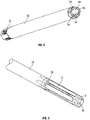
Figure 1 is a schematic perspective view of the distal end of a cannula in a retracted configuration according to an exemplary embodiment of the present invention. -
Figure 2 is a schematic perspective view of the distal end of a cannula according to an exemplary embodiment of the present invention showing a single tool finger wherein representations of the remaining tool fingers have been removed for clarity purposes. -
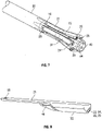
Figure 3 is a schematic perspective view of the distal end of a cannula according to an exemplary embodiment of the present invention wherein the tool fingers are in an expanded or splayed configuration. -
Figure 4 is a schematic perspective view of the distal end of the cannula showing one tool finger for clarity purposes. -
Figure 5 is a schematic perspective view of the arrangement of the cannula showing therein the tool conduits extending in the longitudinal length of the cannula. -
Figure 6 is a schematic perspective view of the distal end of the cannula according to an alternative second exemplary embodiment of the present invention. -
Figure 7 is a schematic perspective view of the distal end of the cannula in the expanded configuration according a second exemplary embodiment of the present invention. -
Figure 8 is a schematic perspective view of a tool finger for use in a second exemplary embodiment of the present invention. - Referring to
Figures 1 to 5 there is an exemplary embodiment that shows an arrangement that overcomes problems associated with a multiplicity of probes and services required at the distal or working end of the cannula. The exemplary embodiments incorporate within their design several of the functions that otherwise would have to be placed in an alternative cannula or would have to be placed down the primary cannula following extraction of a first probe. - The present arrangement comprises three major sections. The distal end or the working tip end that will enter the patient is shown in the Figures. This distal end of the cannula is positioned adjacent to the point of the surgical zone requiring the necessary procedures. The second section is the stem of the cannula that forms an integral part of the distal end. The proximal end of the cannula resides outside the patient and will form or include the handset that contains the various entry ducts and connections for the integral system as well as providing access for the associated surgical instruments.
- The distal end of the cannula comprises one or more tool elements in the form of
fingers 21 having a head orhousing portion 22 arranged to contain the various functions. A variety of functions or tools may be provided as previously described such as a camera, a suction inlet and a conduit for receipt of debris, or a light source such as a LED as such example. In the exemplary embodiment there are provided fourfingers 21 and various tools are provided atsites sites tool finger 21 is beneficially elongate in the longitudinal axis of thecannula 20 and thehead 22 is movable outwardly and beneficially radially in relation to the longitudinal axis of thecannula 20. This may be achieved in various ways however in the exemplary embodiment eachtool finger 21 is secured to thecannula 20 at fixingpoint 28. Thetool finger 21 acts as a leaf spring and effectively is arranged to deflect about thefixing point 28. This is beneficial as thetool finger 21 is enabled to deflect elastically. This provides the benefit that once a force is removed atool finger 21 returns to its original "at rest" configuration improving ease of insertion of thecannula 20 due to the effective constant outer diameter in the retracted configuration. This also works in reverse meaning that when thecannula 20 is ready for removal from the patient the tool finger returns to the original "at rest" configuration for ease of removal and reduction in impact to the surrounding tissue. - The
head 22 is enlarged relative to the remaining portion of thetool finger 21. This configuration enables accommodation of the particular tool. It will be appreciated that in the event that the tool simply comprises a conduit then the required space is not as large as if, for example, the tool is an LED light. However, such a configuration is beneficial in that the distal end of thecannula 20 is therefore symmetrical meaning improved insertion characteristics. Furthermore, the opening of the conduit is ensured to be of a specified and predetermined cross sectional area. - It is beneficial that the
tool finger 21 is riveted to thecannula 20 at fixingpoint 28 in order to provide a smooth outer surface for insertion and removal from a patient. - As will be seen in
Figure 1 , in such a configuration wherein the tool fingers are in the contracted configuration there is no access for a surgical tool.Figure 3 shows thetool fingers 21 in a splayed configuration. The tool fingers are configurable from a rest or contracted configuration to a splayed configuration. Splaying of the one ormore tool fingers 21 may be achieved by a variety of options. A drive ring for example (not shown) which may be actuated from the proximal end of thecannula 20 by a surgeon may be provided which presents motion and force at aleading edge 30 of thehead 22. The leadingedge 30 is preferably provided by a radially inner surface of thetool finger 21. The leadingedge 30 is beneficially tapered inwardly towards the opening of thecannula 20 meaning that in the contracted or rest configuration the effective opening at the tip of thecannula 20 is minimal. The drive ring may move axially pushing against the leadingedge 30 causing thetool finger 21 to deflect about thefixing point 28. - Alternatively, deflection of the
tool finger 21 may be achieved by the mechanical passage of a probe or tool which slides through the centre of the cluster oftool fingers 21 and accordingly causes the tool fingers to splay in a radial manner. The probe such as an endoscopic probe or surgical tool pushes against the leadingedge 30 thereby splaying thetool fingers 21. It is envisaged that other arrangements for causing the tool fingers to splay may be provided. - With reference in particular to
Figure 2 , atool finger 21 defines a conduit therethrough in communication with thehead 22. Accordingly, thetool conduit 32 communicates either with the tool that may be provided in thehead 22 or alternatively with the conduit or opening provided within the head. Thetool conduit 32 projects in the longitudinal length of thetool finger 21. Thetool conduit 32 then communicates with asecondary conduit 34 that extends through the longitudinal length of the cannula. Beneficially, thetool conduit 32 and thesecondary conduit 34 are integrally formed with each other. Thesecondary conduit 34 nests adjacent the inside wall of theprimary cannula 20. Thesecondary conduit 34 extends from the handset end of theprimary cannula 20 and projects through thetool conduit 32 to thehead 22 at the tip of thetool finger 21. Through thissecondary cannula 34 services such as suction irrigation and electrical connections to the functions contained with thehead 22 are provided. - As the
tool finger 21 is arranged to splay or articulate, a proportional degree of motion must occur in thetool conduit 32. In one embodiment this degree of motion is achieved by placing a series of slots 36 (optionally helically) arranged to enable free motion that will not impinge upon the natural spring action of thetool finger 21. Theseslots 36 are also arranged to ensure a condition of motion to thetool finger 21 which will have a secondary effect to create an angle of presentation for the tool functions such as a direction of irrigation or the site of a camera. This motion created ensures a continuous secondary conduit and ensures a flexible nature of this conduit. The intervening gaps presented by the slots may be sealed with an elastomer that bridges the width of the cut and reinstates the hermetic nature of the secondary conduit. It is, however, envisaged that alternative means of providing flexibility to thetool conduit 32 may be achieved. It is also noted that the cross sectional area of thetool conduit 32 andsecondary conduit 34 is shaped such that the inner surface that defines the conduit of the primary cannula is curved to define a primary conduit of generally round cross section. - The
slots 36 are better shown inFigure 4 and clearly show anelastomer 38 therebetween.Figure 5 more carefully illustrates the continuation of theprimary conduit 40 and thesecondary conduits 34 that nest adjacently in a surface of thecannula 20. The internal surface configuration of thesecondary conduits 34 define an approximate cylindrical cross section of theprimary conduit 40 enabling ease of passage of a surgical tool. - In use in one embodiment a force is applied to a drive ring which causes a radial element to slide along the leading
edge 30 causing thetool fingers 21 to be driven laterally away from the central access of the cannula. In an alternative embodiment it is a surgical tool passed down theprimary conduit 40 that acts on the leadingedge 30 of each of thetool fingers 21 causing the lateral movement of the tool fingers. Either of these motions causes movement of thehead 22 radially outwardly as a result of thetool finger 21 deflecting about thefixing point 28. The surgeon can then ensure accurate location of the surgical tool which has not been shown in the Figures through theprimary conduit 40 which is beneficially assisted by at least one of the functions provided in ahead 22 such as a camera and/or light. Each function is operable by the surgeon at the proximal end of thecannula 20 and one or more of the functions can be used at the same time meaning the surgeon has much improved access to the surgical area as waste material can easily be removed and a light and camera are ensured to be close to the area in which the surgical instrument is operated. - As indicated above, there are a number of ways of achieving the motion of splaying of the
tool fingers 21. Each of the tool fingers is beneficially splayed to the same degree. In other words, thetool head 22 of each of thetool fingers 21 is laterally moved by the same amount. As indicated above, this can be achieved by a variety of alternative configurations such as, for example, a concentric sleeve extending to and over thetool fingers 21 such that when the concentric sleeve is withdrawn (slid back) theindividual tool fingers 21 naturally splay as a result of residual spring tendency. To return to the non-splayed configuration, the surgical tool would be withdrawn from the distal end whereupon the concentric sleeve would slide forward and over the splayed tool fingers causing a return to a concentric profile. Such an action may include wiping by the concentric sleeve to remove any tissue that may have built up between thetool fingers 21 thus ensuring an unobstructed collapse and clean withdrawal. - In an alternative embodiment, a hydraulic force may be applied to each
tool finger 21 which may be self-contained within eachtool finger 21 and fed by a micro-bore capillary tube from an integral actuator at the handset end of the individualsecondary conduit 34. In such an embodiment, each hydraulic element could be entirely self contained in a sealed system. - A further significant advantageous feature of the arrangement as described is that it may be dismantled into its key elements for cleaning and sterilisation. It enables removal and replacement of a
tool head 22 ortool finger 21 as required. - Referring to
Figures 6 to 8 , there is an alternative embodiment of the present invention wherein thetool fingers 21 seat within openings provided at the distal end of thecannula 20. The tool fingers are beneficially secured at fixingpoint 28 and project longitudinally relative to thecannula 20. A single tool finger is shown inFigure 8 . In such an embodiment thedistal end 44 of thecannula 20 remains of a substantially constant diameter through which the surgical tool projects. Thetool fingers 21 may be provided set back from thedistal end 44 and a portion of thetool finger 21 is moveable between a contracted and expanded configuration where in expanded configuration, thetool sites tool head 22 into which a tool is accommodated. - As shown in
Figure 8 , a profiledsection 46 is provided for receipt of a drive ring which causes a radial element to slide along the profiledsection 46 provided on the underside of thetool finger 21 such that the tool fingers are driven laterally and away from the central access of thecannula 20. In doing so eachtool finger 21 deflects thus driving thehead 22 of thetool finger 21 outwardly thereby allowing unrestricted access for the surgical tool passing through theprimary conduit 40. - Aspects of the present invention have been described by way of example only and it will be appreciated by the skilled addressee that modifications and variations may be made without departing from the scope of protection afforded by the appended claims.
Claims (8)
- A cannula having a distal end for insertion into a body, the distal end defining an opening to a primary conduit (40) extending along the longitudinal axis of the cannula (20) defining a tool pathway, the cannula further comprising a plurality of tool fingers (21) positioned at or adjacent to the distal end of the cannula for providing a tool function at or adjacent to the distal end of the cannula (20), wherein each tool finger (21) defines a tool conduit in communication with the head of that tool finger, the tool conduit in communication with a respective secondary conduit that extends through the longitudinal length of the cannula, extending in the longitudinal length of the cannula, wherein the plurality of tool fingers (21) are each secured at a proximal end (28) of the cannula (20) and each have a head (22) at the distal end of the tool finger for providing a tool function, at least one of the plurality of heads having a camera provided therein, wherein each of the tool fingers elastically deflect such that the heads of the tool fingers are moveable outwardly relative to the longitudinal axis of the cannula (20) and the proximal ends of each tool finger between a first configuration wherein at least part of each head (22) at least partially occludes the primary conduit (40), and a laterally shifted configuration where each of the fingers is elastically deflected outwardly and wherein each head (22) is at least partially withdrawn from the primary conduit (40).
- A cannula according to claim 1, wherein the head (22) is a receiving conduit in communication with the tool conduit.
- A cannula according to any preceding claim, wherein the plurality of tool fingers (21) are arranged at the distal end of the cannula to define the opening to the primary conduit (40).
- A cannula according to any preceding claim comprising an actuator arrangement for causing outward movement of the tool finger (21).
- A cannula according to claim 4, wherein the actuator arrangement comprises a user operable actuator at or adjacent a proximal end of the cannula, and an actuator element adjacent the tool finger.
- A cannula according to any preceding claim wherein a light source is accommodated in one of the plurality of heads.
- A cannula according to any preceding claim wherein the tool fingers (21) are arranged to splay outwardly to the laterally shifted configuration.
- A cannula according to any preceding claim wherein the plurality of tool fingers comprise four tool fingers.
Applications Claiming Priority (2)
| Application Number | Priority Date | Filing Date | Title |
|---|---|---|---|
| GB1204912.8A GB2502767B (en) | 2012-03-21 | 2012-03-21 | Cannula |
| PCT/GB2013/050734 WO2013140172A1 (en) | 2012-03-21 | 2013-03-21 | Cannula |
Publications (2)
| Publication Number | Publication Date |
|---|---|
| EP2827788A1 EP2827788A1 (en) | 2015-01-28 |
| EP2827788B1 true EP2827788B1 (en) | 2022-09-07 |
Family
ID=46052260
Family Applications (1)
| Application Number | Title | Priority Date | Filing Date |
|---|---|---|---|
| EP13724329.1A Active EP2827788B1 (en) | 2012-03-21 | 2013-03-21 | Cannula |
Country Status (6)
| Country | Link |
|---|---|
| US (1) | US9713482B2 (en) |
| EP (1) | EP2827788B1 (en) |
| CN (1) | CN104321027B (en) |
| AU (1) | AU2013237167B2 (en) |
| GB (1) | GB2502767B (en) |
| WO (1) | WO2013140172A1 (en) |
Families Citing this family (11)
| Publication number | Priority date | Publication date | Assignee | Title |
|---|---|---|---|---|
| WO2015029040A1 (en) | 2013-08-31 | 2015-03-05 | Morena Medical Applications Ltd. | Endoscope with shared working channel |
| JP6393535B2 (en) * | 2014-07-07 | 2018-09-19 | 京セラオプテック株式会社 | Trocar assembly |
| US10543010B2 (en) * | 2015-07-23 | 2020-01-28 | Boston Scientific Scimed, Inc. | Medical device and related methods |
| US9913570B2 (en) * | 2015-08-07 | 2018-03-13 | Enlightenvue Llc | Endoscope with variable profile tip |
| WO2017070183A1 (en) * | 2015-10-23 | 2017-04-27 | Cook Medical Technologies Llc | Endoscope cap with deflecting channels for endoscopic therapy |
| EP3481329B1 (en) | 2016-07-07 | 2021-05-26 | Fawarsy, Summer | A system for the cleaning and disinfecting of gum surfaces surrounding implant structures that support dentures |
| EP3554334A2 (en) | 2017-03-29 | 2019-10-23 | Boston Scientific Scimed, Inc. | Devices and methods for tissue retraction |
| CN106943114B (en) * | 2017-04-27 | 2019-01-08 | 泗洪县正心医疗技术有限公司 | A kind of expandable endoscope in end |
| CA3075487A1 (en) | 2017-06-30 | 2019-01-03 | Enlightenvue Llc | Endoscopy systems and methods of use thereof |
| CA2993590A1 (en) * | 2017-09-06 | 2019-03-06 | Xpan Inc. | Radially expandable cannula system |
| US10687698B2 (en) | 2018-09-12 | 2020-06-23 | Enlightenvue Llc | Direct endoluminal- and/or endovascular-illumination systems and methods of use thereof |
Citations (1)
| Publication number | Priority date | Publication date | Assignee | Title |
|---|---|---|---|---|
| WO2009134634A2 (en) * | 2008-04-28 | 2009-11-05 | Vivid Medical, Inc. | Pluggable vision module and portable display for endoscopy |
Family Cites Families (17)
| Publication number | Priority date | Publication date | Assignee | Title |
|---|---|---|---|---|
| US5224954A (en) * | 1991-02-19 | 1993-07-06 | Dexide, Inc. | Combination surgical trocar cannula and rake assembly |
| US5683384A (en) * | 1993-11-08 | 1997-11-04 | Zomed | Multiple antenna ablation apparatus |
| US5957937A (en) * | 1996-11-27 | 1999-09-28 | Yoon; Inbae | Suturing instrument with spreadable needle holder mounted for arcuate movement |
| EP1054703B1 (en) * | 1998-12-09 | 2004-09-15 | Cook Incorporated | Hollow, curved, superelastic medical needle |
| JP2006503641A (en) * | 2002-10-23 | 2006-02-02 | インテリムド サージカル ソリューションズ、エルエルシー | Direct view port part dissector |
| US7029435B2 (en) | 2003-10-16 | 2006-04-18 | Granit Medical Innovation, Llc | Endoscope having multiple working segments |
| US8562516B2 (en) * | 2004-04-14 | 2013-10-22 | Usgi Medical Inc. | Methods and apparatus for obtaining endoluminal access |
| DE102005003632A1 (en) * | 2005-01-20 | 2006-08-17 | Fraunhofer-Gesellschaft zur Förderung der angewandten Forschung e.V. | Catheter for the transvascular implantation of heart valve prostheses |
| US9596980B2 (en) * | 2007-04-25 | 2017-03-21 | Karl Storz Endovision, Inc. | Endoscope system with pivotable arms |
| AU2008202055A1 (en) * | 2007-05-17 | 2008-12-04 | Cathrx Ltd | A catheter sheath |
| WO2009076176A1 (en) * | 2007-12-07 | 2009-06-18 | Edward Diao | Endoscopic system for accessing constrained surgical spaces |
| JP2012521811A (en) * | 2009-03-27 | 2012-09-20 | エンドスフィア サージカル, インコーポレイテッド | Cannula with integrated camera and illumination |
| US8888687B2 (en) * | 2009-10-28 | 2014-11-18 | Boston Scientific Scimed, Inc. | Method and apparatus related to a flexible assembly at a distal end portion of a medical device |
| US9775640B2 (en) * | 2009-11-14 | 2017-10-03 | SPI Surgical, Inc. | Surgical device |
| US20110166455A1 (en) | 2010-01-07 | 2011-07-07 | Cully Edward H | Catheter |
| CN202027613U (en) * | 2011-03-15 | 2011-11-09 | 浙江海洋学院 | Fork-shaped puncturing sleeve needle |
| US8708889B2 (en) * | 2011-10-24 | 2014-04-29 | Trocare, LLC | Jawed trocar assembly |
-
2012
- 2012-03-21 GB GB1204912.8A patent/GB2502767B/en active Active
-
2013
- 2013-03-21 US US14/386,557 patent/US9713482B2/en active Active
- 2013-03-21 EP EP13724329.1A patent/EP2827788B1/en active Active
- 2013-03-21 AU AU2013237167A patent/AU2013237167B2/en active Active
- 2013-03-21 WO PCT/GB2013/050734 patent/WO2013140172A1/en not_active Ceased
- 2013-03-21 CN CN201380026339.2A patent/CN104321027B/en active Active
Patent Citations (1)
| Publication number | Priority date | Publication date | Assignee | Title |
|---|---|---|---|---|
| WO2009134634A2 (en) * | 2008-04-28 | 2009-11-05 | Vivid Medical, Inc. | Pluggable vision module and portable display for endoscopy |
Also Published As
| Publication number | Publication date |
|---|---|
| EP2827788A1 (en) | 2015-01-28 |
| GB2502767A (en) | 2013-12-11 |
| US9713482B2 (en) | 2017-07-25 |
| US20150065794A1 (en) | 2015-03-05 |
| AU2013237167B2 (en) | 2017-11-02 |
| CN104321027B (en) | 2017-07-28 |
| GB2502767B (en) | 2017-12-06 |
| GB201204912D0 (en) | 2012-05-02 |
| CN104321027A (en) | 2015-01-28 |
| AU2013237167A1 (en) | 2014-10-23 |
| WO2013140172A1 (en) | 2013-09-26 |
Similar Documents
| Publication | Publication Date | Title |
|---|---|---|
| US9713482B2 (en) | Cannula | |
| US10869658B2 (en) | Devices for introducing multiple instruments and methods of use | |
| JP7144871B2 (en) | Tissue clip application attachment set/retrofit set | |
| AU777658B2 (en) | Endoscope instrument having reduced backlash during insertion | |
| US6071233A (en) | Endoscope | |
| US9993233B2 (en) | Large capacity biopsy forceps | |
| CN111163715A (en) | Adjustable Anatomical Channel Dilation Device | |
| EP2311394A1 (en) | Cannulated arthroscopic knife | |
| US20150320406A1 (en) | Sampling catheter devices, methods, and systems | |
| US20170112361A1 (en) | Endoscope cap with deflecting channels for endoscopic therapy | |
| JP2022552042A (en) | Insertable Robot for Minimally Invasive Surgery | |
| US20250235085A1 (en) | Modular endoscope imaging guidewire systems and methods | |
| CN107920810A (en) | Tissue recycling utensil and tissue recovery system | |
| US20110160532A1 (en) | Endoscopic instrument | |
| WO1993008867A2 (en) | Apparatus for laparoscopic and endoscopic surgery | |
| JP5319043B2 (en) | Endoscopic puncture needle and endoscope apparatus | |
| CN108567509B (en) | A kind of equipment for percutaneously conveying cardiac implant by directly applying driving force in vitro | |
| US20250040916A1 (en) | Medical brushes with multiple degrees of freedom and related methods | |
| US20220354515A1 (en) | Endoscopic side snare tools and methods for use | |
| US20190175010A1 (en) | Multi-function cannulated surgical device and systems thereof | |
| CN118119326A (en) | Modular endoscopic imaging guidewire system and method |
Legal Events
| Date | Code | Title | Description |
|---|---|---|---|
| PUAI | Public reference made under article 153(3) epc to a published international application that has entered the european phase |
Free format text: ORIGINAL CODE: 0009012 |
|
| 17P | Request for examination filed |
Effective date: 20141009 |
|
| AK | Designated contracting states |
Kind code of ref document: A1 Designated state(s): AL AT BE BG CH CY CZ DE DK EE ES FI FR GB GR HR HU IE IS IT LI LT LU LV MC MK MT NL NO PL PT RO RS SE SI SK SM TR |
|
| AX | Request for extension of the european patent |
Extension state: BA ME |
|
| DAX | Request for extension of the european patent (deleted) | ||
| RAP1 | Party data changed (applicant data changed or rights of an application transferred) |
Owner name: SURGICAL SYNERGY LIMITED |
|
| RIN1 | Information on inventor provided before grant (corrected) |
Inventor name: SURGICAL SYNERGY LIMITED |
|
| STAA | Information on the status of an ep patent application or granted ep patent |
Free format text: STATUS: EXAMINATION IS IN PROGRESS |
|
| 17Q | First examination report despatched |
Effective date: 20210330 |
|
| GRAP | Despatch of communication of intention to grant a patent |
Free format text: ORIGINAL CODE: EPIDOSNIGR1 |
|
| STAA | Information on the status of an ep patent application or granted ep patent |
Free format text: STATUS: GRANT OF PATENT IS INTENDED |
|
| RIC1 | Information provided on ipc code assigned before grant |
Ipc: A61B 17/29 20060101ALN20220216BHEP Ipc: A61B 17/02 20060101ALI20220216BHEP Ipc: A61B 90/30 20160101ALI20220216BHEP Ipc: A61B 1/00 20060101ALI20220216BHEP Ipc: A61B 17/34 20060101AFI20220216BHEP |
|
| INTG | Intention to grant announced |
Effective date: 20220302 |
|
| GRAS | Grant fee paid |
Free format text: ORIGINAL CODE: EPIDOSNIGR3 |
|
| GRAA | (expected) grant |
Free format text: ORIGINAL CODE: 0009210 |
|
| STAA | Information on the status of an ep patent application or granted ep patent |
Free format text: STATUS: THE PATENT HAS BEEN GRANTED |
|
| AK | Designated contracting states |
Kind code of ref document: B1 Designated state(s): AL AT BE BG CH CY CZ DE DK EE ES FI FR GB GR HR HU IE IS IT LI LT LU LV MC MK MT NL NO PL PT RO RS SE SI SK SM TR |
|
| REG | Reference to a national code |
Ref country code: GB Ref legal event code: FG4D |
|
| RIN1 | Information on inventor provided before grant (corrected) |
Inventor name: JOHN, ROGER Inventor name: KNIGHT, MARTIN |
|
| REG | Reference to a national code |
Ref country code: CH Ref legal event code: EP Ref country code: AT Ref legal event code: REF Ref document number: 1516423 Country of ref document: AT Kind code of ref document: T Effective date: 20220915 |
|
| REG | Reference to a national code |
Ref country code: DE Ref legal event code: R096 Ref document number: 602013082462 Country of ref document: DE |
|
| REG | Reference to a national code |
Ref country code: IE Ref legal event code: FG4D |
|
| REG | Reference to a national code |
Ref country code: LT Ref legal event code: MG9D |
|
| REG | Reference to a national code |
Ref country code: NL Ref legal event code: MP Effective date: 20220907 |
|
| PG25 | Lapsed in a contracting state [announced via postgrant information from national office to epo] |
Ref country code: SE Free format text: LAPSE BECAUSE OF FAILURE TO SUBMIT A TRANSLATION OF THE DESCRIPTION OR TO PAY THE FEE WITHIN THE PRESCRIBED TIME-LIMIT Effective date: 20220907 Ref country code: RS Free format text: LAPSE BECAUSE OF FAILURE TO SUBMIT A TRANSLATION OF THE DESCRIPTION OR TO PAY THE FEE WITHIN THE PRESCRIBED TIME-LIMIT Effective date: 20220907 Ref country code: NO Free format text: LAPSE BECAUSE OF FAILURE TO SUBMIT A TRANSLATION OF THE DESCRIPTION OR TO PAY THE FEE WITHIN THE PRESCRIBED TIME-LIMIT Effective date: 20221207 Ref country code: LV Free format text: LAPSE BECAUSE OF FAILURE TO SUBMIT A TRANSLATION OF THE DESCRIPTION OR TO PAY THE FEE WITHIN THE PRESCRIBED TIME-LIMIT Effective date: 20220907 Ref country code: LT Free format text: LAPSE BECAUSE OF FAILURE TO SUBMIT A TRANSLATION OF THE DESCRIPTION OR TO PAY THE FEE WITHIN THE PRESCRIBED TIME-LIMIT Effective date: 20220907 Ref country code: FI Free format text: LAPSE BECAUSE OF FAILURE TO SUBMIT A TRANSLATION OF THE DESCRIPTION OR TO PAY THE FEE WITHIN THE PRESCRIBED TIME-LIMIT Effective date: 20220907 Ref country code: ES Free format text: LAPSE BECAUSE OF FAILURE TO SUBMIT A TRANSLATION OF THE DESCRIPTION OR TO PAY THE FEE WITHIN THE PRESCRIBED TIME-LIMIT Effective date: 20220907 |
|
| REG | Reference to a national code |
Ref country code: AT Ref legal event code: MK05 Ref document number: 1516423 Country of ref document: AT Kind code of ref document: T Effective date: 20220907 |
|
| PG25 | Lapsed in a contracting state [announced via postgrant information from national office to epo] |
Ref country code: HR Free format text: LAPSE BECAUSE OF FAILURE TO SUBMIT A TRANSLATION OF THE DESCRIPTION OR TO PAY THE FEE WITHIN THE PRESCRIBED TIME-LIMIT Effective date: 20220907 Ref country code: GR Free format text: LAPSE BECAUSE OF FAILURE TO SUBMIT A TRANSLATION OF THE DESCRIPTION OR TO PAY THE FEE WITHIN THE PRESCRIBED TIME-LIMIT Effective date: 20221208 |
|
| PG25 | Lapsed in a contracting state [announced via postgrant information from national office to epo] |
Ref country code: SM Free format text: LAPSE BECAUSE OF FAILURE TO SUBMIT A TRANSLATION OF THE DESCRIPTION OR TO PAY THE FEE WITHIN THE PRESCRIBED TIME-LIMIT Effective date: 20220907 Ref country code: RO Free format text: LAPSE BECAUSE OF FAILURE TO SUBMIT A TRANSLATION OF THE DESCRIPTION OR TO PAY THE FEE WITHIN THE PRESCRIBED TIME-LIMIT Effective date: 20220907 Ref country code: PT Free format text: LAPSE BECAUSE OF FAILURE TO SUBMIT A TRANSLATION OF THE DESCRIPTION OR TO PAY THE FEE WITHIN THE PRESCRIBED TIME-LIMIT Effective date: 20230109 Ref country code: CZ Free format text: LAPSE BECAUSE OF FAILURE TO SUBMIT A TRANSLATION OF THE DESCRIPTION OR TO PAY THE FEE WITHIN THE PRESCRIBED TIME-LIMIT Effective date: 20220907 Ref country code: AT Free format text: LAPSE BECAUSE OF FAILURE TO SUBMIT A TRANSLATION OF THE DESCRIPTION OR TO PAY THE FEE WITHIN THE PRESCRIBED TIME-LIMIT Effective date: 20220907 |
|
| PG25 | Lapsed in a contracting state [announced via postgrant information from national office to epo] |
Ref country code: SK Free format text: LAPSE BECAUSE OF FAILURE TO SUBMIT A TRANSLATION OF THE DESCRIPTION OR TO PAY THE FEE WITHIN THE PRESCRIBED TIME-LIMIT Effective date: 20220907 Ref country code: PL Free format text: LAPSE BECAUSE OF FAILURE TO SUBMIT A TRANSLATION OF THE DESCRIPTION OR TO PAY THE FEE WITHIN THE PRESCRIBED TIME-LIMIT Effective date: 20220907 Ref country code: IS Free format text: LAPSE BECAUSE OF FAILURE TO SUBMIT A TRANSLATION OF THE DESCRIPTION OR TO PAY THE FEE WITHIN THE PRESCRIBED TIME-LIMIT Effective date: 20230107 Ref country code: EE Free format text: LAPSE BECAUSE OF FAILURE TO SUBMIT A TRANSLATION OF THE DESCRIPTION OR TO PAY THE FEE WITHIN THE PRESCRIBED TIME-LIMIT Effective date: 20220907 |
|
| REG | Reference to a national code |
Ref country code: DE Ref legal event code: R097 Ref document number: 602013082462 Country of ref document: DE |
|
| PG25 | Lapsed in a contracting state [announced via postgrant information from national office to epo] |
Ref country code: NL Free format text: LAPSE BECAUSE OF FAILURE TO SUBMIT A TRANSLATION OF THE DESCRIPTION OR TO PAY THE FEE WITHIN THE PRESCRIBED TIME-LIMIT Effective date: 20220907 Ref country code: AL Free format text: LAPSE BECAUSE OF FAILURE TO SUBMIT A TRANSLATION OF THE DESCRIPTION OR TO PAY THE FEE WITHIN THE PRESCRIBED TIME-LIMIT Effective date: 20220907 |
|
| PLBE | No opposition filed within time limit |
Free format text: ORIGINAL CODE: 0009261 |
|
| STAA | Information on the status of an ep patent application or granted ep patent |
Free format text: STATUS: NO OPPOSITION FILED WITHIN TIME LIMIT |
|
| PG25 | Lapsed in a contracting state [announced via postgrant information from national office to epo] |
Ref country code: DK Free format text: LAPSE BECAUSE OF FAILURE TO SUBMIT A TRANSLATION OF THE DESCRIPTION OR TO PAY THE FEE WITHIN THE PRESCRIBED TIME-LIMIT Effective date: 20220907 |
|
| 26N | No opposition filed |
Effective date: 20230608 |
|
| PG25 | Lapsed in a contracting state [announced via postgrant information from national office to epo] |
Ref country code: SI Free format text: LAPSE BECAUSE OF FAILURE TO SUBMIT A TRANSLATION OF THE DESCRIPTION OR TO PAY THE FEE WITHIN THE PRESCRIBED TIME-LIMIT Effective date: 20220907 |
|
| REG | Reference to a national code |
Ref country code: DE Ref legal event code: R119 Ref document number: 602013082462 Country of ref document: DE |
|
| PG25 | Lapsed in a contracting state [announced via postgrant information from national office to epo] |
Ref country code: MC Free format text: LAPSE BECAUSE OF FAILURE TO SUBMIT A TRANSLATION OF THE DESCRIPTION OR TO PAY THE FEE WITHIN THE PRESCRIBED TIME-LIMIT Effective date: 20220907 |
|
| REG | Reference to a national code |
Ref country code: CH Ref legal event code: PL |
|
| GBPC | Gb: european patent ceased through non-payment of renewal fee |
Effective date: 20230321 |
|
| REG | Reference to a national code |
Ref country code: BE Ref legal event code: MM Effective date: 20230331 |
|
| PG25 | Lapsed in a contracting state [announced via postgrant information from national office to epo] |
Ref country code: LU Free format text: LAPSE BECAUSE OF NON-PAYMENT OF DUE FEES Effective date: 20230321 |
|
| REG | Reference to a national code |
Ref country code: IE Ref legal event code: MM4A |
|
| PG25 | Lapsed in a contracting state [announced via postgrant information from national office to epo] |
Ref country code: GB Free format text: LAPSE BECAUSE OF NON-PAYMENT OF DUE FEES Effective date: 20230321 |
|
| PG25 | Lapsed in a contracting state [announced via postgrant information from national office to epo] |
Ref country code: LI Free format text: LAPSE BECAUSE OF NON-PAYMENT OF DUE FEES Effective date: 20230331 Ref country code: IE Free format text: LAPSE BECAUSE OF NON-PAYMENT OF DUE FEES Effective date: 20230321 Ref country code: GB Free format text: LAPSE BECAUSE OF NON-PAYMENT OF DUE FEES Effective date: 20230321 Ref country code: FR Free format text: LAPSE BECAUSE OF NON-PAYMENT OF DUE FEES Effective date: 20230331 Ref country code: DE Free format text: LAPSE BECAUSE OF NON-PAYMENT OF DUE FEES Effective date: 20231003 Ref country code: CH Free format text: LAPSE BECAUSE OF NON-PAYMENT OF DUE FEES Effective date: 20230331 |
|
| PG25 | Lapsed in a contracting state [announced via postgrant information from national office to epo] |
Ref country code: BE Free format text: LAPSE BECAUSE OF NON-PAYMENT OF DUE FEES Effective date: 20230331 |
|
| PG25 | Lapsed in a contracting state [announced via postgrant information from national office to epo] |
Ref country code: IT Free format text: LAPSE BECAUSE OF FAILURE TO SUBMIT A TRANSLATION OF THE DESCRIPTION OR TO PAY THE FEE WITHIN THE PRESCRIBED TIME-LIMIT Effective date: 20220907 |
|
| PG25 | Lapsed in a contracting state [announced via postgrant information from national office to epo] |
Ref country code: BG Free format text: LAPSE BECAUSE OF FAILURE TO SUBMIT A TRANSLATION OF THE DESCRIPTION OR TO PAY THE FEE WITHIN THE PRESCRIBED TIME-LIMIT Effective date: 20220907 |
|
| PG25 | Lapsed in a contracting state [announced via postgrant information from national office to epo] |
Ref country code: BG Free format text: LAPSE BECAUSE OF FAILURE TO SUBMIT A TRANSLATION OF THE DESCRIPTION OR TO PAY THE FEE WITHIN THE PRESCRIBED TIME-LIMIT Effective date: 20220907 |
|
| PG25 | Lapsed in a contracting state [announced via postgrant information from national office to epo] |
Ref country code: CY Free format text: LAPSE BECAUSE OF FAILURE TO SUBMIT A TRANSLATION OF THE DESCRIPTION OR TO PAY THE FEE WITHIN THE PRESCRIBED TIME-LIMIT; INVALID AB INITIO Effective date: 20130321 |
|
| PG25 | Lapsed in a contracting state [announced via postgrant information from national office to epo] |
Ref country code: HU Free format text: LAPSE BECAUSE OF FAILURE TO SUBMIT A TRANSLATION OF THE DESCRIPTION OR TO PAY THE FEE WITHIN THE PRESCRIBED TIME-LIMIT; INVALID AB INITIO Effective date: 20130321 |
|
| PG25 | Lapsed in a contracting state [announced via postgrant information from national office to epo] |
Ref country code: TR Free format text: LAPSE BECAUSE OF FAILURE TO SUBMIT A TRANSLATION OF THE DESCRIPTION OR TO PAY THE FEE WITHIN THE PRESCRIBED TIME-LIMIT Effective date: 20220907 |