EP2827778B1 - A method for determining right ventricle stroke volume - Google Patents
A method for determining right ventricle stroke volume Download PDFInfo
- Publication number
- EP2827778B1 EP2827778B1 EP13765098.2A EP13765098A EP2827778B1 EP 2827778 B1 EP2827778 B1 EP 2827778B1 EP 13765098 A EP13765098 A EP 13765098A EP 2827778 B1 EP2827778 B1 EP 2827778B1
- Authority
- EP
- European Patent Office
- Prior art keywords
- volume
- region
- right ventricle
- images
- interest
- Prior art date
- Legal status (The legal status is an assumption and is not a legal conclusion. Google has not performed a legal analysis and makes no representation as to the accuracy of the status listed.)
- Not-in-force
Links
Images



Classifications
-
- A—HUMAN NECESSITIES
- A61—MEDICAL OR VETERINARY SCIENCE; HYGIENE
- A61B—DIAGNOSIS; SURGERY; IDENTIFICATION
- A61B5/00—Measuring for diagnostic purposes; Identification of persons
- A61B5/02—Detecting, measuring or recording for evaluating the cardiovascular system, e.g. pulse, heart rate, blood pressure or blood flow
- A61B5/026—Measuring blood flow
- A61B5/029—Measuring blood output from the heart, e.g. minute volume
-
- A—HUMAN NECESSITIES
- A61—MEDICAL OR VETERINARY SCIENCE; HYGIENE
- A61B—DIAGNOSIS; SURGERY; IDENTIFICATION
- A61B8/00—Diagnosis using ultrasonic, sonic or infrasonic waves
- A61B8/06—Measuring blood flow
- A61B8/065—Measuring blood flow to determine blood output from the heart
-
- A—HUMAN NECESSITIES
- A61—MEDICAL OR VETERINARY SCIENCE; HYGIENE
- A61B—DIAGNOSIS; SURGERY; IDENTIFICATION
- A61B8/00—Diagnosis using ultrasonic, sonic or infrasonic waves
- A61B8/08—Clinical applications
- A61B8/0883—Clinical applications for diagnosis of the heart
-
- A—HUMAN NECESSITIES
- A61—MEDICAL OR VETERINARY SCIENCE; HYGIENE
- A61B—DIAGNOSIS; SURGERY; IDENTIFICATION
- A61B8/00—Diagnosis using ultrasonic, sonic or infrasonic waves
- A61B8/48—Diagnostic techniques
- A61B8/483—Diagnostic techniques involving the acquisition of a 3D volume of data
-
- A—HUMAN NECESSITIES
- A61—MEDICAL OR VETERINARY SCIENCE; HYGIENE
- A61B—DIAGNOSIS; SURGERY; IDENTIFICATION
- A61B8/00—Diagnosis using ultrasonic, sonic or infrasonic waves
- A61B8/52—Devices using data or image processing specially adapted for diagnosis using ultrasonic, sonic or infrasonic waves
- A61B8/5215—Devices using data or image processing specially adapted for diagnosis using ultrasonic, sonic or infrasonic waves involving processing of medical diagnostic data
- A61B8/5223—Devices using data or image processing specially adapted for diagnosis using ultrasonic, sonic or infrasonic waves involving processing of medical diagnostic data for extracting a diagnostic or physiological parameter from medical diagnostic data
-
- A—HUMAN NECESSITIES
- A61—MEDICAL OR VETERINARY SCIENCE; HYGIENE
- A61B—DIAGNOSIS; SURGERY; IDENTIFICATION
- A61B8/00—Diagnosis using ultrasonic, sonic or infrasonic waves
- A61B8/52—Devices using data or image processing specially adapted for diagnosis using ultrasonic, sonic or infrasonic waves
- A61B8/5215—Devices using data or image processing specially adapted for diagnosis using ultrasonic, sonic or infrasonic waves involving processing of medical diagnostic data
- A61B8/523—Devices using data or image processing specially adapted for diagnosis using ultrasonic, sonic or infrasonic waves involving processing of medical diagnostic data for generating planar views from image data in a user selectable plane not corresponding to the acquisition plane
-
- G—PHYSICS
- G06—COMPUTING OR CALCULATING; COUNTING
- G06T—IMAGE DATA PROCESSING OR GENERATION, IN GENERAL
- G06T7/00—Image analysis
- G06T7/10—Segmentation; Edge detection
- G06T7/12—Edge-based segmentation
-
- G—PHYSICS
- G06—COMPUTING OR CALCULATING; COUNTING
- G06T—IMAGE DATA PROCESSING OR GENERATION, IN GENERAL
- G06T7/00—Image analysis
- G06T7/60—Analysis of geometric attributes
- G06T7/62—Analysis of geometric attributes of area, perimeter, diameter or volume
-
- G—PHYSICS
- G16—INFORMATION AND COMMUNICATION TECHNOLOGY [ICT] SPECIALLY ADAPTED FOR SPECIFIC APPLICATION FIELDS
- G16H—HEALTHCARE INFORMATICS, i.e. INFORMATION AND COMMUNICATION TECHNOLOGY [ICT] SPECIALLY ADAPTED FOR THE HANDLING OR PROCESSING OF MEDICAL OR HEALTHCARE DATA
- G16H50/00—ICT specially adapted for medical diagnosis, medical simulation or medical data mining; ICT specially adapted for detecting, monitoring or modelling epidemics or pandemics
- G16H50/30—ICT specially adapted for medical diagnosis, medical simulation or medical data mining; ICT specially adapted for detecting, monitoring or modelling epidemics or pandemics for calculating health indices; for individual health risk assessment
-
- F—MECHANICAL ENGINEERING; LIGHTING; HEATING; WEAPONS; BLASTING
- F04—POSITIVE - DISPLACEMENT MACHINES FOR LIQUIDS; PUMPS FOR LIQUIDS OR ELASTIC FLUIDS
- F04C—ROTARY-PISTON, OR OSCILLATING-PISTON, POSITIVE-DISPLACEMENT MACHINES FOR LIQUIDS; ROTARY-PISTON, OR OSCILLATING-PISTON, POSITIVE-DISPLACEMENT PUMPS
- F04C2270/00—Control; Monitoring or safety arrangements
- F04C2270/04—Force
- F04C2270/042—Force radial
- F04C2270/0421—Controlled or regulated
-
- G—PHYSICS
- G06—COMPUTING OR CALCULATING; COUNTING
- G06T—IMAGE DATA PROCESSING OR GENERATION, IN GENERAL
- G06T2207/00—Indexing scheme for image analysis or image enhancement
- G06T2207/10—Image acquisition modality
- G06T2207/10132—Ultrasound image
-
- G—PHYSICS
- G06—COMPUTING OR CALCULATING; COUNTING
- G06T—IMAGE DATA PROCESSING OR GENERATION, IN GENERAL
- G06T2207/00—Indexing scheme for image analysis or image enhancement
- G06T2207/10—Image acquisition modality
- G06T2207/10132—Ultrasound image
- G06T2207/10136—3D ultrasound image
-
- G—PHYSICS
- G06—COMPUTING OR CALCULATING; COUNTING
- G06T—IMAGE DATA PROCESSING OR GENERATION, IN GENERAL
- G06T2207/00—Indexing scheme for image analysis or image enhancement
- G06T2207/30—Subject of image; Context of image processing
- G06T2207/30004—Biomedical image processing
- G06T2207/30048—Heart; Cardiac
Definitions
- This invention relates to a method for measuring stroke volume, and more particularly to a method for measuring stroke volume of a right ventricle.
- US Patent 4,674,518 disclosed a cardiac monitoring apparatus, more particularly to a method and apparatus for quantitatively measuring the instantaneous ventricular volume contained within a given chamber of a heart using an intracavity electrical impedance catheter having plural pairs of spaced surface electrodes driven by a corresponding plurality of electrical signals, each of the signals exhibiting a different discrete frequency, and having plural pairs of spaced surface electrodes for sensing the potentials at predetermined locations within the ventricle.
- the apparatus enable stroke volume and cardiac output to be continuously monitored.
- the cited patent involves the use of catheter which needs to be inserted into patient's body and this could cause discomfort and pain to the patient while the monitoring is taking place.
- Kovalova et. Al. (2005) disclosed optimal geometric model for two-dimensional volumetry of right ventricle and its clinical validation. It disclosed that an ellipsoidal shell model best reflects the complex right ventricular geometry. Measurements of right ventricular stroke volume were made in modified apical four chamber and parasternal short axis views both in end-diastole and end-systole. The cited article mentioned that some of the result has poor quality of echocardiographic images. Besides that, the cited article used two-dimensional echocardiography which produces low precision of result and did not account for the variability of right ventricular outflow tract in patients.
- the present invention relates to a method as defined by claim 1. Further embodiments of the invention are defined by the dependent claims.
- the present invention relates to a method for determining right ventricle stroke volume comprising the steps of:
- the three-dimensional are full volume real-time echocardiogram.
- Frame rate refers to how many times in a second, an image is updated. In each frame, there could be consecutive images produced by the echocardiography.
- the frame rate is not a constant for a machine.
- time unit refers to frame per motion for each change of the shape of the right ventricle cavity. The time unit is not representing any measuring unit but shows each change of the right ventricle cavity.
- the step of identically slicing each of the plurality of images comprises the steps of:
- the plurality of images may be sliced into 4, 9, and 16 slices. It is preferred that the plurality of images is sliced into 16 slices.
- the primary image is selected to be sliced first to provide a standard impression on the plurality of images of the right cardiac ventricle of the patient produced by the machine.
- the region of interest is determined using region growing method and spline tools.
- Region growing is a simple-based image segmentation method. Region growing method involves selection of initial seed points. The approach to segmentation examines neighbouring pixels of initial seed points and determines whether the pixel neighbours should be added to the region. Seed point is the initial point for a set of region growing. Seed point can be a pixel or a group of pixels which are able to reflect character of an object in image. The selection of seed points may be chosen by using the mean of grey scale value of four neighbouring pixels which can be obtained when calculation of volume of each slice is obtained. After the seed points are selected, spline tools are used to connect the seed points together to form an area. Spline tools are used to enable user to easily create smooth, curved, and precision shapes of the region of interest.
- the input is an image of the right cardiac ventricle of a patient provided by an ultrasound machine.
- resolution of 3-dimensional transducer of the ultrasound machine is first determined.
- a test object for example a piece of meat, is used to determine the resolution of the transducer.
- the real size of the object is measured.
- a first ultrasound image is produced using the ultrasound machine.
- the number of pixels in the first image of the object is counted.
- the object is then moved to change the distance between the object and the transducer, and a second image of the object is created.
- the resolution in inches / pixel is multiplied with a constant 2.54 to obtain resolution in centimetres / pixel.
- the resolution obtained from the above calculation is 0.0304697 cm/pixel.
- input comprising the plurality of three-dimensional images of the right cardiac ventricle of the patient over a cardiac cycle is received from the echocardiography machine.
- the frame rate is not a constant for a machine and this applies to the echocardiography used in this example.
- the patient has 73 images during one cardiac cycle.
- Each of the plurality of images is identically sliced.
- One of the ways to perform identical slicing to each of the plurality of images is by selecting a primary image from the plurality of images.
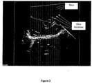
- An example of the primary image is shown in figure 2 which is taken at time unit t 1 .
- the primary image is sliced into a plurality of slices.
- FIG 2 a coronal plane ultrasound image sliced in the parallel sagittal plane
- the plurality of slices is imprinted on subsequent images of said plurality of images so that all of the plurality of images is identically sliced.
- first time unit, t 1 takes one image
- second time unit, t 2 takes 4 images
- third time unit, t 3 takes 5 images
- fourth time unit, t 4 takes 4 images and so on.
- the third time unit, t 3 takes 5 images to show a change of the shape of the right ventricle cavity after the change in t 2 .
- the change could be significant in only one of the 5 images or the 5 images could show the gradual change of the right ventricle cavity in t 3 .
- the one image showing the change of the right ventricle cavity is selected; if the latter occurs, the image showing most significant change among the 5 images of the right ventricle cavity is selected.
- the significant change herein can be the image that shows most apparent change compared to the selected image of the right ventricle cavity in previous time unit.
- the region of interest for each of the plurality of slices of the selected images is determined, wherein the region of interest shows the right ventricle of the patient.
- the region of interest in each slice is determined using region growing method.
- the seed point is the initial point for set of region growing. It can be a pixel or group of pixels able to reflect the region of interest in the ultrasound image of right cardiac ventricle.
- the minimum pixel intensity in the image is needed for automatic detection of the threshold.
- the region with the minimum pixel intensity is selected for threshold according to the value of the pixels.
- the image will then be converted to black and white image by the machine.
- Each area of the region with the minimum pixel intensity in the image is recorded and a centre of gravity of the area of the region is chosen. Due to the in-homogeneity of the ultrasound image of the pixel intensity in the region of interest, mean value of seed point neighbouring values are used.
- Figure 3 shows an ultrasound image of a slice (parallel sagittal plane) at t 1 .
- the desired region of interest in figure 3 is right ventricle cavity, denoted as "RV cavity” in figure 3 and (B) in figure 5 .
- RV cavity right ventricle cavity
- the region of interest is determined as shown in figure 4 and (A) in figure 5 .
- Gaussian filter application may be applied to the image to smoothen the image and eliminate any line existing in the ultrasound image.
- Figure 5 shows the area of the region of interest after being applied with Gaussian filter.
- the area of the region of interest (A) is calculated.
- volume area ⁇ slice thickness
- the area is as calculated by using equation (1) previously.
- the slice thickness is measured as the distance between two slices (referring to figure 2 ).
- Example data of the volume is shown in table 2.
- the total volume of the region of interest for each time unit is then determined wherein the maximum total volume is the end diastolic volume and the minimum total volume is the end systolic volume. Example of this data is also shown in table 2.
- This calculation is performed for each of the time units t 1 - t 15 of the cardiac cycle.
- end systolic volume is the minimum total volume over all the time units in the cardiac cycle and end diastolic volume is the maximum total volume over all the time units in the cardiac cycle, as shown in table 2.
Landscapes
- Health & Medical Sciences (AREA)
- Life Sciences & Earth Sciences (AREA)
- Engineering & Computer Science (AREA)
- Physics & Mathematics (AREA)
- Public Health (AREA)
- Medical Informatics (AREA)
- Biomedical Technology (AREA)
- Pathology (AREA)
- General Health & Medical Sciences (AREA)
- Veterinary Medicine (AREA)
- Animal Behavior & Ethology (AREA)
- Surgery (AREA)
- Molecular Biology (AREA)
- Heart & Thoracic Surgery (AREA)
- Biophysics (AREA)
- Radiology & Medical Imaging (AREA)
- Nuclear Medicine, Radiotherapy & Molecular Imaging (AREA)
- Computer Vision & Pattern Recognition (AREA)
- Cardiology (AREA)
- Hematology (AREA)
- General Physics & Mathematics (AREA)
- Theoretical Computer Science (AREA)
- Physiology (AREA)
- Geometry (AREA)
- Data Mining & Analysis (AREA)
- Primary Health Care (AREA)
- Epidemiology (AREA)
- Databases & Information Systems (AREA)
- Ultra Sonic Daignosis Equipment (AREA)
- Magnetic Resonance Imaging Apparatus (AREA)
Description
- This invention relates to a method for measuring stroke volume, and more particularly to a method for measuring stroke volume of a right ventricle.
- As early as 1950s - 1970s, cardiologist recognised the importance of right ventricle function in heart filter, congenital heart disease and pulmonary hypertension. The assessment of right ventricle congenital function and anatomy remains a big challenge using two-dimensional echo because of its complex geometry. With poor resolution of two-dimensional image and the pre-processing which leads to possible loss of information, the right ventricle modelling is very difficult and inaccurate. The right ventricle stroke volume is an important measure of right ventricle function. Therefore, there is a need for an accurate method of measuring the stroke volume. "Real-time Three-dimensional Echocardiography for Determining Right Ventricular Stroke Volume in an Animal Model of Chronic Right Ventricular Volume Overload", by Shiota et al. (Circulation 1998;97:1897-1900) discloses a method for determining right ventricle stroke volume by obtaining a plurality of three-dimensional images of the right ventricle over a cardiac cycle, selecting the end diastolic and end systolic images and determining the right ventricular stroke volume as the difference between end diastolic and end systolic volumes.
US Patent 4,674,518 disclosed a cardiac monitoring apparatus, more particularly to a method and apparatus for quantitatively measuring the instantaneous ventricular volume contained within a given chamber of a heart using an intracavity electrical impedance catheter having plural pairs of spaced surface electrodes driven by a corresponding plurality of electrical signals, each of the signals exhibiting a different discrete frequency, and having plural pairs of spaced surface electrodes for sensing the potentials at predetermined locations within the ventricle. The apparatus enable stroke volume and cardiac output to be continuously monitored. The cited patent involves the use of catheter which needs to be inserted into patient's body and this could cause discomfort and pain to the patient while the monitoring is taking place. - Kovalova et. Al. (2005) disclosed optimal geometric model for two-dimensional volumetry of right ventricle and its clinical validation. It disclosed that an ellipsoidal shell model best reflects the complex right ventricular geometry. Measurements of right ventricular stroke volume were made in modified apical four chamber and parasternal short axis views both in end-diastole and end-systole. The cited article mentioned that some of the result has poor quality of echocardiographic images. Besides that, the cited article used two-dimensional echocardiography which produces low precision of result and did not account for the variability of right ventricular outflow tract in patients.
- Accordingly, it can be seen in the prior arts that there exists a need to provide a method for measuring stroke volume of right ventricle that is not painful to patient and has a better visualisation and accuracy of the end result.
-
- Kovalova, S., Necas, J., Cerbak, R., Malik, P., and Vespalec, J. (2005) "Echocardiographic Volumetry of The Right Ventricle", European Journal of Echocardiography, Vol. 6, page 15-23.
- It is an objective of the present invention to provide a method for measuring stroke volume of right ventricle that is accurate and has involves minimal manual manipulation and correction.
- It is also an objective of the present invention to provide a method for measuring stroke volume of right ventricle that provides good visualisation of the heart.
- Accordingly, these objectives may be achieved by following the teachings of the present invention. The present invention relates to a method as defined by claim 1. Further embodiments of the invention are defined by the dependent claims.
- The features of the invention will be more readily understood and appreciated from the following detailed description when read in conjunction with the accompanying drawings of the preferred embodiment of the present invention, in which:
-
Figure 1 is a flow chart of a method of measuring right ventricle stroke volume. -
Figure 2 is a coronal plane ultrasound image, of an input of a full volume image of right ventricle at t1, showing a plurality of slices. -
Figure 3 is a parallel sagittal plane slice of an ultrasound image at t1. -
Figure 4 is a parallel sagittal plane slice of an ultrasound image at t1 showing determination of region of interest in the slice. -
Figure 5 is parallel sagittal plane slice of an ultrasound image at t1, showing (A) region of interest, shown herein as bolded region; (B) a right ventricle cavity which is the region of interest. - As required, detailed embodiments of the present invention are disclosed herein; however, it is to be understood that the disclosed embodiments are merely exemplary of the invention, which may be embodied in various forms. Therefore, specific structural and functional details disclosed herein are not to be interpreted as limiting but merely as a basis for claims. It should be understood that the drawings and detailed description thereto are not intended to limit the invention to the particular form disclosed, but on the contrary, the invention is to cover all modification, equivalents and alternatives falling within the scope of the present invention as defined by the appended claims. As used throughout this application, the word "may" is used in a permissive sense (i.e., meaning having the potential to), rather than the mandatory sense (i.e., meaning must). Similarly, the words "include," "including," and "includes" mean including, but not limited to. Further, the words "a" or "an" mean "at least one" and the word "plurality" means one or more, unless otherwise mentioned. Where the abbreviations or technical terms are used, these indicate the commonly accepted meanings as known in the technical field. For ease of reference, common reference numerals will be used throughout the figures when referring to the same or similar features common to the figures. The present invention will now be described with reference to
Figures 1-5 . - The present invention relates to a method for determining right ventricle stroke volume comprising the steps of:
- providing a plurality of three-dimensional images of right cardiac ventricle of a patient over a cardiac cycle;
- identically slicing each of the plurality of images;
- selecting an image from the plurality of images, for each time unit of the cardiac cycle;
- determining a region of interest in each slice of the selected images, wherein the region of interest shows the right ventricle of the patient;
- determining area of the region of interest;
- determining volume of the region of interest;
- determining total volume of the region of interest for each time unit, wherein the maximum total volume is end diastolic volume and the minimum total volume is end systolic volume; and
- determining the right ventricle stroke volume using an equation:

- The method of the present invention is illustrated in
Figure 1 . - In a preferred embodiment, the three-dimensional are full volume real-time echocardiogram.
- Through the cardiac cycle, the heart cavity changes and each change is captured in a frame by the machine. Frame rate refers to how many times in a second, an image is updated. In each frame, there could be consecutive images produced by the echocardiography. The frame rate is not a constant for a machine. The term "time unit" as used herein refers to frame per motion for each change of the shape of the right ventricle cavity. The time unit is not representing any measuring unit but shows each change of the right ventricle cavity.
- In a preferred embodiment, the step of identically slicing each of the plurality of images comprises the steps of:
- selecting a primary image from the plurality of images;
- slicing said primary image to produce a plurality of slices; and
- imprinting the plurality of slices on subsequent images of said plurality of images;
- In a preferred embodiment, the plurality of images may be sliced into 4, 9, and 16 slices. It is preferred that the plurality of images is sliced into 16 slices. The primary image is selected to be sliced first to provide a standard impression on the plurality of images of the right cardiac ventricle of the patient produced by the machine.
- In a preferred embodiment, the region of interest is determined using region growing method and spline tools. Region growing is a simple-based image segmentation method. Region growing method involves selection of initial seed points. The approach to segmentation examines neighbouring pixels of initial seed points and determines whether the pixel neighbours should be added to the region. Seed point is the initial point for a set of region growing. Seed point can be a pixel or a group of pixels which are able to reflect character of an object in image. The selection of seed points may be chosen by using the mean of grey scale value of four neighbouring pixels which can be obtained when calculation of volume of each slice is obtained. After the seed points are selected, spline tools are used to connect the seed points together to form an area. Spline tools are used to enable user to easily create smooth, curved, and precision shapes of the region of interest.
- In a preferred embodiment, the area of the region of interest for each slice is determined using an equation:

- In a preferred embodiment, the volume of the region of interest for each slice is determined using an equation:

- Below is an example of the method for measuring right ventricle stroke volume from which the advantages of the present invention may be more readily understood. It is to be understood that the following example is for illustrative purpose only and should not be construed to limit the present invention in any way.
- Below is an example of the method for measuring right ventricle stroke volume.
- In the following example, the input is an image of the right cardiac ventricle of a patient provided by an ultrasound machine. As the parameters given by the ultrasound machine may be inadequate to calculate image resolution, resolution of 3-dimensional transducer of the ultrasound machine is first determined. In a preferred embodiment, the resolution of the input is predetermined using an equation:

- A test object, for example a piece of meat, is used to determine the resolution of the transducer. The real size of the object is measured. A first ultrasound image is produced using the ultrasound machine.
- The number of pixels in the first image of the object is counted. The object is then moved to change the distance between the object and the transducer, and a second image of the object is created.
- The change in number of pixels depending on the change of distance between the object and the transducer is recorded. Resolution is then calculated using equation (4). Then the average of resolution in all iterations is calculated. The example data is shown in table 1 below.
Table 1: Example data for measuring resolution of the transducer. Iteration (p) Probe Distance (cm) no. of pixels in image Real size of object (cm) Resolution =cm/pixel 1. 1 94.51 1 0.010581 2. 1 118.01 1 0.008474 3. 1 124.1 1 0.008058 4. 1 60.01 1 0.016664 5. 1 135.77 1 0.007365 6. 1 131.15 1 0.007625 7. 1 135.02 1 0.007406 8. 1 60.8 1 0.016447 9. 1 207.51 2.5 0.012048 10. 1 135.01 1 0.007407 11. 1 139.86 1 0.00715 12. 1 107.25 2.5 0.02331 13. 2 96.01 1 0.010416 14. 2 142.25 1 0.00703 15. 2 208.5 2.5 0.01199 16. 4 78.92 1 0.012671 17. 4 51.85 1 0.019286 18. 4 113.64 2.5 0.021999 n = 18 Total Scale 0.215927 Resolution 0.011996 inch/pixel Resolution in cm 0.0304697 cm/pixel - In a preferred embodiment, the resolution in inches / pixel is multiplied with a constant 2.54 to obtain resolution in centimetres / pixel.
- The resolution obtained from the above calculation is 0.0304697 cm/pixel.
- After pre-determining the resolution, input comprising the plurality of three-dimensional images of the right cardiac ventricle of the patient over a cardiac cycle is received from the echocardiography machine.
- The frame rate is not a constant for a machine and this applies to the echocardiography used in this example. In this example, the patient has 73 images during one cardiac cycle.
- Frame per motion for each change of the shape of the heart cavity is denoted as time unit (t1-t15) in table 2.
- Each of the plurality of images is identically sliced. One of the ways to perform identical slicing to each of the plurality of images is by selecting a primary image from the plurality of images. An example of the primary image is shown in
figure 2 which is taken at time unit t1. Then, the primary image is sliced into a plurality of slices. As shown infigure 2 (a coronal plane ultrasound image sliced in the parallel sagittal plane), there are 16 slices. Then, the plurality of slices is imprinted on subsequent images of said plurality of images so that all of the plurality of images is identically sliced. - An image from the plurality of image is selected for each time unit of the cardiac cycle. For example, in this patient, first time unit, t1, takes one image; second time unit, t2, takes 4 images; third time unit, t3, takes 5 images; fourth time unit, t4, takes 4 images and so on. In further explanation, for example, the third time unit, t3, takes 5 images to show a change of the shape of the right ventricle cavity after the change in t2. The change could be significant in only one of the 5 images or the 5 images could show the gradual change of the right ventricle cavity in t3. When the former occurs, the one image showing the change of the right ventricle cavity is selected; if the latter occurs, the image showing most significant change among the 5 images of the right ventricle cavity is selected. The significant change herein can be the image that shows most apparent change compared to the selected image of the right ventricle cavity in previous time unit.
- For each of the selected images, the region of interest for each of the plurality of slices of the selected images is determined, wherein the region of interest shows the right ventricle of the patient. The region of interest in each slice is determined using region growing method.
- The seed point is the initial point for set of region growing. It can be a pixel or group of pixels able to reflect the region of interest in the ultrasound image of right cardiac ventricle. The minimum pixel intensity in the image is needed for automatic detection of the threshold. The region with the minimum pixel intensity is selected for threshold according to the value of the pixels. The image will then be converted to black and white image by the machine. Each area of the region with the minimum pixel intensity in the image is recorded and a centre of gravity of the area of the region is chosen. Due to the in-homogeneity of the ultrasound image of the pixel intensity in the region of interest, mean value of seed point neighbouring values are used.
-
Figure 3 shows an ultrasound image of a slice (parallel sagittal plane) at t1. The desired region of interest infigure 3 is right ventricle cavity, denoted as "RV cavity" infigure 3 and (B) infigure 5 . Then, by using region growing method and spline tools, the region of interest is determined as shown infigure 4 and (A) infigure 5 . - If the ultrasound image is noisy and unclear, Gaussian filter application may be applied to the image to smoothen the image and eliminate any line existing in the ultrasound image.
Figure 5 shows the area of the region of interest after being applied with Gaussian filter. - Referring to
figure 5 , the area of the region of interest (A) is calculated. - The area of the region of interest is calculated by using equation (1):

- Then, the volume of the area of the region of interest is determined.

- The area is as calculated by using equation (1) previously. The slice thickness is measured as the distance between two slices (referring to
figure 2 ). - Referring to
figure 2 , if the distance between each cut is 15 pixels and a resolution of 0.0304697 is as previously calculated, therefore the slice thickness is:
- Example data of the volume is shown in table 2.
- The total volume of the region of interest for each time unit is then determined wherein the maximum total volume is the end diastolic volume and the minimum total volume is the end systolic volume. Example of this data is also shown in table 2.
- The total volume of the region of interest for the plurality of slices 1-16 in the selected image for t1 (referring to table 2) is calculated as:

- This calculation is performed for each of the time units t1 - t15 of the cardiac cycle.
- Then, the right ventricle stroke volume is determined using equation (3):

- In table 1 of this example, the end of systole is at t8 as t8 shows the lowest total volume (end systolic volume) over the cardiac cycle and the end of diastole is at t15 as t15 shows the highest total volume (end diastolic volume) over the cardiac cycle. Both values of t15 and t8 are applied to equation (3):

- The end systolic volume is the minimum total volume over all the time units in the cardiac cycle and end diastolic volume is the maximum total volume over all the time units in the cardiac cycle, as shown in table 2.
- Although the present invention has been described with reference to specific embodiments, also shown in the appended figures, it will be apparent for those skilled in the art that many variations and modifications can be done within the scope of the invention as described in the specification and defined in the following claims.

Claims (6)
- A method for determining right ventricle stroke volume comprising the steps of:(a) providing as input a plurality of three-dimensional images of right cardiac ventricle of a patient over a cardiac cycle;(b) identically slicing each of the plurality of images;(c) for each time unit of the cardiac cycle, selecting the image of the time unit showing the most significant change of the right ventricle cavity as compared to the selected image in the previous time unit;(d) determining a region of interest in each slice of the selected images, wherein the region of interest shows the right ventricle of the patient;(e) determining area of the region of interest;(f) determining volume of the region of interest;(g) determining total volume of the region of interest for each time unit, wherein the maximum total volume is end diastolic volume and the minimum total volume is end systolic volume; and(h) determining the right ventricle stroke volume using an equation:

- A method for determining right ventricle stroke volume, according to claim 1, wherein the three-dimensional images are full volume real-time echocardiogram images.
- A method for determining right ventricle stroke volume, according to claim 1, wherein the step of identically slicing each of the plurality of images comprises the steps of:(i) selecting a primary image from the plurality of images;(ii) slicing said primary image to produce a plurality of slices; and(iii) imprinting the plurality of slices on subsequent images of said plurality of images, thereby identically slicing each of the plurality of images.
- A method for determining right ventricle stroke volume, according to claim 1, wherein the region of interest is determined using region growing method and spline tools.
- A method for determining right ventricle stroke volume, according to claim 1, wherein the area of the region of interest for each slice is determined using an equation:

- A method for determining right ventricle stroke volume, according to claim 1, wherein the volume of the region of interest for each slice is determined using an equation:

Applications Claiming Priority (2)
| Application Number | Priority Date | Filing Date | Title |
|---|---|---|---|
| MYPI2012001329A MY177355A (en) | 2012-03-23 | 2012-03-23 | A method for determining right ventricle stroke volume |
| PCT/MY2013/000060 WO2013141694A1 (en) | 2012-03-23 | 2013-03-22 | A method for determining right ventricle stroke volume |
Publications (3)
| Publication Number | Publication Date |
|---|---|
| EP2827778A1 EP2827778A1 (en) | 2015-01-28 |
| EP2827778A4 EP2827778A4 (en) | 2015-12-02 |
| EP2827778B1 true EP2827778B1 (en) | 2018-01-31 |
Family
ID=49223045
Family Applications (1)
| Application Number | Title | Priority Date | Filing Date |
|---|---|---|---|
| EP13765098.2A Not-in-force EP2827778B1 (en) | 2012-03-23 | 2013-03-22 | A method for determining right ventricle stroke volume |
Country Status (4)
| Country | Link |
|---|---|
| US (1) | US9498141B2 (en) |
| EP (1) | EP2827778B1 (en) |
| MY (1) | MY177355A (en) |
| WO (1) | WO2013141694A1 (en) |
Families Citing this family (3)
| Publication number | Priority date | Publication date | Assignee | Title |
|---|---|---|---|---|
| EP3494893A1 (en) | 2017-12-05 | 2019-06-12 | Koninklijke Philips N.V. | Ultrasound imaging system and method |
| CN108703770B (en) * | 2018-04-08 | 2021-10-01 | 智谷医疗科技(广州)有限公司 | Ventricular volume monitoring device and method |
| CN117918889B (en) * | 2024-03-20 | 2024-07-19 | 中国医学科学院北京协和医院 | Automatic calculation method and device for left ventricular cardiac output of transesophageal echocardiography four-chamber cardiac tangential plane |
Family Cites Families (12)
| Publication number | Priority date | Publication date | Assignee | Title |
|---|---|---|---|---|
| US6730032B2 (en) * | 2001-03-05 | 2004-05-04 | Matsushita Electric Industrial Co. | Ultrasonic diagnostic device and image processing device |
| US20060025689A1 (en) * | 2002-06-07 | 2006-02-02 | Vikram Chalana | System and method to measure cardiac ejection fraction |
| US6628743B1 (en) | 2002-11-26 | 2003-09-30 | Ge Medical Systems Global Technology Company, Llc | Method and apparatus for acquiring and analyzing cardiac data from a patient |
| DE10260762A1 (en) * | 2002-12-23 | 2004-07-22 | Pulsion Medical Systems Ag | Device for determining cardiovascular parameters |
| US7689261B2 (en) | 2003-11-26 | 2010-03-30 | General Electric Company | Cardiac display methods and apparatus |
| WO2008144490A1 (en) * | 2007-05-16 | 2008-11-27 | Massachusetts Instutute Of Technology | Systems and methods for model-based estimation of cardiac ejection fraction, cardiac contractility, and ventricular end-diastolic volume |
| WO2008154632A2 (en) * | 2007-06-12 | 2008-12-18 | University Of Virginia Patent Foundation | System and method for combined ecg-echo for cardiac diagnosis |
| US20110105931A1 (en) * | 2007-11-20 | 2011-05-05 | Siemens Medical Solutions Usa, Inc. | System for Determining Patient Heart related Parameters for use in Heart Imaging |
| JP5619584B2 (en) * | 2010-01-13 | 2014-11-05 | 株式会社東芝 | Ultrasonic diagnostic apparatus, ultrasonic image processing apparatus, and ultrasonic image processing program |
| JP5624481B2 (en) * | 2010-02-03 | 2014-11-12 | 株式会社東芝 | Ultrasonic diagnostic apparatus and medical image processing apparatus |
| US10321892B2 (en) * | 2010-09-27 | 2019-06-18 | Siemens Medical Solutions Usa, Inc. | Computerized characterization of cardiac motion in medical diagnostic ultrasound |
| US20140301624A1 (en) * | 2011-11-25 | 2014-10-09 | Circle Cardiovascular Imaging Inc. | Method for interactive threshold segmentation of medical images |
-
2012
- 2012-03-23 MY MYPI2012001329A patent/MY177355A/en unknown
-
2013
- 2013-03-22 WO PCT/MY2013/000060 patent/WO2013141694A1/en not_active Ceased
- 2013-03-22 EP EP13765098.2A patent/EP2827778B1/en not_active Not-in-force
- 2013-03-22 US US14/386,831 patent/US9498141B2/en not_active Expired - Fee Related
Non-Patent Citations (1)
| Title |
|---|
| None * |
Also Published As
| Publication number | Publication date |
|---|---|
| MY177355A (en) | 2020-09-14 |
| EP2827778A1 (en) | 2015-01-28 |
| US20150078638A1 (en) | 2015-03-19 |
| US9498141B2 (en) | 2016-11-22 |
| WO2013141694A1 (en) | 2013-09-26 |
| EP2827778A4 (en) | 2015-12-02 |
Similar Documents
| Publication | Publication Date | Title |
|---|---|---|
| Riehle et al. | Real-time three-dimensional echocardiographic acquisition and quantification of left ventricular indices in children and young adults with congenital heart disease: comparison with magnetic resonance imaging | |
| EP3697311B1 (en) | Ultrasound imaging system | |
| Iwataki et al. | Measurement of left atrial volume from transthoracic three-dimensional echocardiographic datasets using the biplane Simpson’s technique | |
| CN114901154A (en) | Intravascular image based vessel diameter determination and associated devices, systems, and methods | |
| JP2021524767A5 (en) | ||
| Höllmer et al. | Left atrial volume and phasic function in clinically healthy dogs of 12 different breeds | |
| Soliman et al. | Quantification of left ventricular volumes and function in patients with cardiomyopathies by real-time three-dimensional echocardiography: a head-to-head comparison between two different semiautomated endocardial border detection algorithms | |
| CN103648402A (en) | Ultrasonic diagnostic device, image processing device, and image processing method | |
| Esposito et al. | Nonsymmetric myocardial contribution to supranormal right ventricular function in the athlete's heart: combined assessment by speckle tracking and real time three‐dimensional echocardiography | |
| CN101617947A (en) | Cardiac muscle texture automatic analyzing method based on spot tracking technology | |
| CN115330681A (en) | Ultrasonic image measuring method, system, intelligent terminal and storage medium | |
| Kupferwasser et al. | Transthoracic three-dimensional echocardiographic volumetry of distorted left ventricles using rotational scanning | |
| US9498141B2 (en) | Method for determining right ventricle stroke volume | |
| Poutanen et al. | Transthoracic three-dimensional echocardiography is as good as magnetic resonance imaging in measuring dynamic changes in left ventricular volume during the heart cycle in children | |
| Takuma et al. | Determination of Left Ventricular Mass by Real‐Time Three‐Dimensional Echocardiography: In Vitro Validation | |
| Kupari et al. | Systolic flow velocity profile in the left ventricular outflow tract in persons free of heart disease | |
| Tee et al. | Comparative myocardial deformation in 3 myocardial layers in mice by speckle tracking echocardiography | |
| Rodevand et al. | Left ventricular volumes assessed by different new three-dimensional echocardiographic methods and ordinary biplane technique | |
| Heusch et al. | Transesophageal 3-dimensional versus cross-sectional echocardiographic assessment of the volume of the right ventricle in children with atrial septal defects | |
| Osuga et al. | Repeatability and reproducibility of measurements obtained via two-dimensional speckle tracking echocardiography of the left atrium and time-left atrial area curve analysis in healthy dogs | |
| CN107753061B (en) | Automatic optimization method and system for ultrasound elastography | |
| Hayama et al. | A novel non-invasive method for estimating elevated pulmonary vascular resistance based on echocardiographic assessment of pulmonary artery wave reflection | |
| JP6858189B2 (en) | Ultrasound cardiac evaluation of the heart with central axis curvature and lateral eccentricity | |
| Nadkarni et al. | Three-dimensional echocardiography: assessment of inter-and intra-operator variability and accuracy in the measurement of left ventricular cavity volume and myocardial mass | |
| Rodevand et al. | Left ventricular mass assessed by three‐dimensional echocardiography using rotational acquisition |
Legal Events
| Date | Code | Title | Description |
|---|---|---|---|
| PUAI | Public reference made under article 153(3) epc to a published international application that has entered the european phase |
Free format text: ORIGINAL CODE: 0009012 |
|
| 17P | Request for examination filed |
Effective date: 20141023 |
|
| AK | Designated contracting states |
Kind code of ref document: A1 Designated state(s): AL AT BE BG CH CY CZ DE DK EE ES FI FR GB GR HR HU IE IS IT LI LT LU LV MC MK MT NL NO PL PT RO RS SE SI SK SM TR |
|
| AX | Request for extension of the european patent |
Extension state: BA ME |
|
| DAX | Request for extension of the european patent (deleted) | ||
| RA4 | Supplementary search report drawn up and despatched (corrected) |
Effective date: 20151030 |
|
| RIC1 | Information provided on ipc code assigned before grant |
Ipc: A61B 8/00 20060101AFI20151026BHEP Ipc: G06T 7/00 20060101ALI20151026BHEP Ipc: A61B 5/02 20060101ALI20151026BHEP |
|
| GRAP | Despatch of communication of intention to grant a patent |
Free format text: ORIGINAL CODE: EPIDOSNIGR1 |
|
| STAA | Information on the status of an ep patent application or granted ep patent |
Free format text: STATUS: GRANT OF PATENT IS INTENDED |
|
| INTG | Intention to grant announced |
Effective date: 20170802 |
|
| GRAS | Grant fee paid |
Free format text: ORIGINAL CODE: EPIDOSNIGR3 |
|
| GRAA | (expected) grant |
Free format text: ORIGINAL CODE: 0009210 |
|
| STAA | Information on the status of an ep patent application or granted ep patent |
Free format text: STATUS: THE PATENT HAS BEEN GRANTED |
|
| AK | Designated contracting states |
Kind code of ref document: B1 Designated state(s): AL AT BE BG CH CY CZ DE DK EE ES FI FR GB GR HR HU IE IS IT LI LT LU LV MC MK MT NL NO PL PT RO RS SE SI SK SM TR |
|
| REG | Reference to a national code |
Ref country code: GB Ref legal event code: FG4D Ref country code: CH Ref legal event code: EP |
|
| REG | Reference to a national code |
Ref country code: AT Ref legal event code: REF Ref document number: 966610 Country of ref document: AT Kind code of ref document: T Effective date: 20180215 |
|
| REG | Reference to a national code |
Ref country code: IE Ref legal event code: FG4D |
|
| REG | Reference to a national code |
Ref country code: DE Ref legal event code: R096 Ref document number: 602013032648 Country of ref document: DE |
|
| REG | Reference to a national code |
Ref country code: FR Ref legal event code: PLFP Year of fee payment: 6 |
|
| PGFP | Annual fee paid to national office [announced via postgrant information from national office to epo] |
Ref country code: GB Payment date: 20180328 Year of fee payment: 6 |
|
| PGFP | Annual fee paid to national office [announced via postgrant information from national office to epo] |
Ref country code: FR Payment date: 20180328 Year of fee payment: 6 |
|
| REG | Reference to a national code |
Ref country code: NL Ref legal event code: MP Effective date: 20180131 |
|
| REG | Reference to a national code |
Ref country code: LT Ref legal event code: MG4D |
|
| REG | Reference to a national code |
Ref country code: AT Ref legal event code: MK05 Ref document number: 966610 Country of ref document: AT Kind code of ref document: T Effective date: 20180131 |
|
| PG25 | Lapsed in a contracting state [announced via postgrant information from national office to epo] |
Ref country code: FI Free format text: LAPSE BECAUSE OF FAILURE TO SUBMIT A TRANSLATION OF THE DESCRIPTION OR TO PAY THE FEE WITHIN THE PRESCRIBED TIME-LIMIT Effective date: 20180131 Ref country code: NL Free format text: LAPSE BECAUSE OF FAILURE TO SUBMIT A TRANSLATION OF THE DESCRIPTION OR TO PAY THE FEE WITHIN THE PRESCRIBED TIME-LIMIT Effective date: 20180131 Ref country code: HR Free format text: LAPSE BECAUSE OF FAILURE TO SUBMIT A TRANSLATION OF THE DESCRIPTION OR TO PAY THE FEE WITHIN THE PRESCRIBED TIME-LIMIT Effective date: 20180131 Ref country code: ES Free format text: LAPSE BECAUSE OF FAILURE TO SUBMIT A TRANSLATION OF THE DESCRIPTION OR TO PAY THE FEE WITHIN THE PRESCRIBED TIME-LIMIT Effective date: 20180131 Ref country code: LT Free format text: LAPSE BECAUSE OF FAILURE TO SUBMIT A TRANSLATION OF THE DESCRIPTION OR TO PAY THE FEE WITHIN THE PRESCRIBED TIME-LIMIT Effective date: 20180131 Ref country code: NO Free format text: LAPSE BECAUSE OF FAILURE TO SUBMIT A TRANSLATION OF THE DESCRIPTION OR TO PAY THE FEE WITHIN THE PRESCRIBED TIME-LIMIT Effective date: 20180430 |
|
| PGFP | Annual fee paid to national office [announced via postgrant information from national office to epo] |
Ref country code: DE Payment date: 20180423 Year of fee payment: 6 |
|
| PG25 | Lapsed in a contracting state [announced via postgrant information from national office to epo] |
Ref country code: IS Free format text: LAPSE BECAUSE OF FAILURE TO SUBMIT A TRANSLATION OF THE DESCRIPTION OR TO PAY THE FEE WITHIN THE PRESCRIBED TIME-LIMIT Effective date: 20180531 Ref country code: GR Free format text: LAPSE BECAUSE OF FAILURE TO SUBMIT A TRANSLATION OF THE DESCRIPTION OR TO PAY THE FEE WITHIN THE PRESCRIBED TIME-LIMIT Effective date: 20180501 Ref country code: RS Free format text: LAPSE BECAUSE OF FAILURE TO SUBMIT A TRANSLATION OF THE DESCRIPTION OR TO PAY THE FEE WITHIN THE PRESCRIBED TIME-LIMIT Effective date: 20180131 Ref country code: AT Free format text: LAPSE BECAUSE OF FAILURE TO SUBMIT A TRANSLATION OF THE DESCRIPTION OR TO PAY THE FEE WITHIN THE PRESCRIBED TIME-LIMIT Effective date: 20180131 Ref country code: BG Free format text: LAPSE BECAUSE OF FAILURE TO SUBMIT A TRANSLATION OF THE DESCRIPTION OR TO PAY THE FEE WITHIN THE PRESCRIBED TIME-LIMIT Effective date: 20180430 Ref country code: SE Free format text: LAPSE BECAUSE OF FAILURE TO SUBMIT A TRANSLATION OF THE DESCRIPTION OR TO PAY THE FEE WITHIN THE PRESCRIBED TIME-LIMIT Effective date: 20180131 Ref country code: LV Free format text: LAPSE BECAUSE OF FAILURE TO SUBMIT A TRANSLATION OF THE DESCRIPTION OR TO PAY THE FEE WITHIN THE PRESCRIBED TIME-LIMIT Effective date: 20180131 Ref country code: PL Free format text: LAPSE BECAUSE OF FAILURE TO SUBMIT A TRANSLATION OF THE DESCRIPTION OR TO PAY THE FEE WITHIN THE PRESCRIBED TIME-LIMIT Effective date: 20180131 |
|
| PG25 | Lapsed in a contracting state [announced via postgrant information from national office to epo] |
Ref country code: EE Free format text: LAPSE BECAUSE OF FAILURE TO SUBMIT A TRANSLATION OF THE DESCRIPTION OR TO PAY THE FEE WITHIN THE PRESCRIBED TIME-LIMIT Effective date: 20180131 Ref country code: IT Free format text: LAPSE BECAUSE OF FAILURE TO SUBMIT A TRANSLATION OF THE DESCRIPTION OR TO PAY THE FEE WITHIN THE PRESCRIBED TIME-LIMIT Effective date: 20180131 Ref country code: RO Free format text: LAPSE BECAUSE OF FAILURE TO SUBMIT A TRANSLATION OF THE DESCRIPTION OR TO PAY THE FEE WITHIN THE PRESCRIBED TIME-LIMIT Effective date: 20180131 Ref country code: AL Free format text: LAPSE BECAUSE OF FAILURE TO SUBMIT A TRANSLATION OF THE DESCRIPTION OR TO PAY THE FEE WITHIN THE PRESCRIBED TIME-LIMIT Effective date: 20180131 |
|
| REG | Reference to a national code |
Ref country code: CH Ref legal event code: PL |
|
| REG | Reference to a national code |
Ref country code: DE Ref legal event code: R097 Ref document number: 602013032648 Country of ref document: DE |
|
| PG25 | Lapsed in a contracting state [announced via postgrant information from national office to epo] |
Ref country code: MC Free format text: LAPSE BECAUSE OF FAILURE TO SUBMIT A TRANSLATION OF THE DESCRIPTION OR TO PAY THE FEE WITHIN THE PRESCRIBED TIME-LIMIT Effective date: 20180131 Ref country code: SK Free format text: LAPSE BECAUSE OF FAILURE TO SUBMIT A TRANSLATION OF THE DESCRIPTION OR TO PAY THE FEE WITHIN THE PRESCRIBED TIME-LIMIT Effective date: 20180131 Ref country code: SM Free format text: LAPSE BECAUSE OF FAILURE TO SUBMIT A TRANSLATION OF THE DESCRIPTION OR TO PAY THE FEE WITHIN THE PRESCRIBED TIME-LIMIT Effective date: 20180131 Ref country code: DK Free format text: LAPSE BECAUSE OF FAILURE TO SUBMIT A TRANSLATION OF THE DESCRIPTION OR TO PAY THE FEE WITHIN THE PRESCRIBED TIME-LIMIT Effective date: 20180131 Ref country code: CZ Free format text: LAPSE BECAUSE OF FAILURE TO SUBMIT A TRANSLATION OF THE DESCRIPTION OR TO PAY THE FEE WITHIN THE PRESCRIBED TIME-LIMIT Effective date: 20180131 |
|
| PLBE | No opposition filed within time limit |
Free format text: ORIGINAL CODE: 0009261 |
|
| STAA | Information on the status of an ep patent application or granted ep patent |
Free format text: STATUS: NO OPPOSITION FILED WITHIN TIME LIMIT |
|
| REG | Reference to a national code |
Ref country code: BE Ref legal event code: MM Effective date: 20180331 |
|
| REG | Reference to a national code |
Ref country code: IE Ref legal event code: MM4A |
|
| PG25 | Lapsed in a contracting state [announced via postgrant information from national office to epo] |
Ref country code: LU Free format text: LAPSE BECAUSE OF NON-PAYMENT OF DUE FEES Effective date: 20180322 |
|
| 26N | No opposition filed |
Effective date: 20181102 |
|
| PG25 | Lapsed in a contracting state [announced via postgrant information from national office to epo] |
Ref country code: IE Free format text: LAPSE BECAUSE OF NON-PAYMENT OF DUE FEES Effective date: 20180322 |
|
| PG25 | Lapsed in a contracting state [announced via postgrant information from national office to epo] |
Ref country code: LI Free format text: LAPSE BECAUSE OF NON-PAYMENT OF DUE FEES Effective date: 20180331 Ref country code: SI Free format text: LAPSE BECAUSE OF FAILURE TO SUBMIT A TRANSLATION OF THE DESCRIPTION OR TO PAY THE FEE WITHIN THE PRESCRIBED TIME-LIMIT Effective date: 20180131 Ref country code: BE Free format text: LAPSE BECAUSE OF NON-PAYMENT OF DUE FEES Effective date: 20180331 Ref country code: CH Free format text: LAPSE BECAUSE OF NON-PAYMENT OF DUE FEES Effective date: 20180331 |
|
| REG | Reference to a national code |
Ref country code: DE Ref legal event code: R119 Ref document number: 602013032648 Country of ref document: DE |
|
| GBPC | Gb: european patent ceased through non-payment of renewal fee |
Effective date: 20190322 |
|
| PG25 | Lapsed in a contracting state [announced via postgrant information from national office to epo] |
Ref country code: GB Free format text: LAPSE BECAUSE OF NON-PAYMENT OF DUE FEES Effective date: 20190322 Ref country code: MT Free format text: LAPSE BECAUSE OF NON-PAYMENT OF DUE FEES Effective date: 20180322 Ref country code: DE Free format text: LAPSE BECAUSE OF NON-PAYMENT OF DUE FEES Effective date: 20191001 |
|
| PG25 | Lapsed in a contracting state [announced via postgrant information from national office to epo] |
Ref country code: FR Free format text: LAPSE BECAUSE OF NON-PAYMENT OF DUE FEES Effective date: 20190331 |
|
| PG25 | Lapsed in a contracting state [announced via postgrant information from national office to epo] |
Ref country code: TR Free format text: LAPSE BECAUSE OF FAILURE TO SUBMIT A TRANSLATION OF THE DESCRIPTION OR TO PAY THE FEE WITHIN THE PRESCRIBED TIME-LIMIT Effective date: 20180131 |
|
| PG25 | Lapsed in a contracting state [announced via postgrant information from national office to epo] |
Ref country code: HU Free format text: LAPSE BECAUSE OF FAILURE TO SUBMIT A TRANSLATION OF THE DESCRIPTION OR TO PAY THE FEE WITHIN THE PRESCRIBED TIME-LIMIT; INVALID AB INITIO Effective date: 20130322 Ref country code: PT Free format text: LAPSE BECAUSE OF FAILURE TO SUBMIT A TRANSLATION OF THE DESCRIPTION OR TO PAY THE FEE WITHIN THE PRESCRIBED TIME-LIMIT Effective date: 20180131 |
|
| PG25 | Lapsed in a contracting state [announced via postgrant information from national office to epo] |
Ref country code: MK Free format text: LAPSE BECAUSE OF NON-PAYMENT OF DUE FEES Effective date: 20180131 Ref country code: CY Free format text: LAPSE BECAUSE OF FAILURE TO SUBMIT A TRANSLATION OF THE DESCRIPTION OR TO PAY THE FEE WITHIN THE PRESCRIBED TIME-LIMIT Effective date: 20180131 |