EP2827456A1 - Connection terminal and connector using same - Google Patents
Connection terminal and connector using same Download PDFInfo
- Publication number
- EP2827456A1 EP2827456A1 EP13761500.1A EP13761500A EP2827456A1 EP 2827456 A1 EP2827456 A1 EP 2827456A1 EP 13761500 A EP13761500 A EP 13761500A EP 2827456 A1 EP2827456 A1 EP 2827456A1
- Authority
- EP
- European Patent Office
- Prior art keywords
- connection terminal
- movable contact
- curved
- terminal according
- curved portion
- Prior art date
- Legal status (The legal status is an assumption and is not a legal conclusion. Google has not performed a legal analysis and makes no representation as to the accuracy of the status listed.)
- Granted
Links
Images





Classifications
-
- H—ELECTRICITY
- H01—ELECTRIC ELEMENTS
- H01R—ELECTRICALLY-CONDUCTIVE CONNECTIONS; STRUCTURAL ASSOCIATIONS OF A PLURALITY OF MUTUALLY-INSULATED ELECTRICAL CONNECTING ELEMENTS; COUPLING DEVICES; CURRENT COLLECTORS
- H01R13/00—Details of coupling devices of the kinds covered by groups H01R12/70 or H01R24/00 - H01R33/00
- H01R13/02—Contact members
- H01R13/04—Pins or blades for co-operation with sockets
- H01R13/05—Resilient pins or blades
-
- H—ELECTRICITY
- H01—ELECTRIC ELEMENTS
- H01R—ELECTRICALLY-CONDUCTIVE CONNECTIONS; STRUCTURAL ASSOCIATIONS OF A PLURALITY OF MUTUALLY-INSULATED ELECTRICAL CONNECTING ELEMENTS; COUPLING DEVICES; CURRENT COLLECTORS
- H01R13/00—Details of coupling devices of the kinds covered by groups H01R12/70 or H01R24/00 - H01R33/00
- H01R13/02—Contact members
- H01R13/22—Contacts for co-operating by abutting
- H01R13/24—Contacts for co-operating by abutting resilient; resiliently-mounted
- H01R13/2407—Contacts for co-operating by abutting resilient; resiliently-mounted characterized by the resilient means
- H01R13/2428—Contacts for co-operating by abutting resilient; resiliently-mounted characterized by the resilient means using meander springs
-
- H—ELECTRICITY
- H01—ELECTRIC ELEMENTS
- H01R—ELECTRICALLY-CONDUCTIVE CONNECTIONS; STRUCTURAL ASSOCIATIONS OF A PLURALITY OF MUTUALLY-INSULATED ELECTRICAL CONNECTING ELEMENTS; COUPLING DEVICES; CURRENT COLLECTORS
- H01R13/00—Details of coupling devices of the kinds covered by groups H01R12/70 or H01R24/00 - H01R33/00
- H01R13/02—Contact members
- H01R13/22—Contacts for co-operating by abutting
- H01R13/24—Contacts for co-operating by abutting resilient; resiliently-mounted
- H01R13/2464—Contacts for co-operating by abutting resilient; resiliently-mounted characterized by the contact point
- H01R13/2492—Contacts for co-operating by abutting resilient; resiliently-mounted characterized by the contact point multiple contact points
-
- H—ELECTRICITY
- H01—ELECTRIC ELEMENTS
- H01R—ELECTRICALLY-CONDUCTIVE CONNECTIONS; STRUCTURAL ASSOCIATIONS OF A PLURALITY OF MUTUALLY-INSULATED ELECTRICAL CONNECTING ELEMENTS; COUPLING DEVICES; CURRENT COLLECTORS
- H01R12/00—Structural associations of a plurality of mutually-insulated electrical connecting elements, specially adapted for printed circuits, e.g. printed circuit boards [PCB], flat or ribbon cables, or like generally planar structures, e.g. terminal strips, terminal blocks; Coupling devices specially adapted for printed circuits, flat or ribbon cables, or like generally planar structures; Terminals specially adapted for contact with, or insertion into, printed circuits, flat or ribbon cables, or like generally planar structures
- H01R12/50—Fixed connections
- H01R12/51—Fixed connections for rigid printed circuits or like structures
- H01R12/55—Fixed connections for rigid printed circuits or like structures characterised by the terminals
- H01R12/57—Fixed connections for rigid printed circuits or like structures characterised by the terminals surface mounting terminals
Definitions
- connection terminal e.g., not only to a connection terminal which is incorporated in a housing to form a connector, but also to a connection terminal which can directly be mounted on a substrate and can be used.
- connection terminal contact on which a connection terminal contact is integrally formed through a spring side having a backbone portion connected to a support side, characterized in that the spring side is formed into a laterally oriented substantially U-shape which is composed of an upper piece arm extending from a connecting portion to the connection terminal contact and a lower piece arm extending toward the backbone portion, the upper piece arm is composed of a first spring portion and a second spring portion which are separated away from each other and which extend in parallel to each other, and a third spring portion and a fourth spring portion which are separated away from each other and which extend in parallel to each other, and the spring side downwardly inclines from the connecting portion toward the backbone portion (see Patent Document 1).
- Patent Document 1 Japanese Patent Publication No. 2001-237015
- the above-described IC socket contact has a problem that if an external force is applied, stress is prone to concentrate on a backbone portion 5, and if an attempt is made to increase a displacement amount, plastic deformation is prone to generate.
- connection terminal which moderates stress concentration and has excellent durability in which a displacement amount can be increased and plastic deformation is less prone to generate.
- a connection terminal of the present invention comprises a movable contact which projects outside from a contact hole of a housing such that the movable contact can be pressed, and a curved portion which is pushed and widened by a load applied to the movable contact.
- connection terminal having an excellent durability, in which even if an external force is applied to a movable contact and the connection terminal elastically deforms, it is possible to prevent stress from being concentrated on a specific location by pushing and widening curved portions, and it is possible to prevent the connection terminal from being plastically deformed.
- connection terminal may further include at least two curved portions, and the curved portions may be connected to each other through a connecting portion.
- connection terminal having small size or depth.
- At least two curved portions may be connected to each other through the connecting portion to form substantially a shape of letter "3".
- connection terminal By connecting the curved portions to each other into a shape of letter "3", it is possible to obtain a connection terminal having smaller size or depth.
- the shape of letter “3” is such a shape that adjacent two of curved portions are connected to each other such that openings of the curved portions are oriented to the same direction and more particularly, the shape of letter “3” is such a shape that openings of the curved portions are oriented to the same direction with respect to a line segment which connects both ends of the adjacent two curved portions.
- a spring constant of the connecting portion may be greater than that of the curved portion.
- the connecting portion serves as a rigid body. Therefore, the plurality of curved portions elastically deform in a direction in which the curved portions are pushed and widened. Hence, it is possible to obtain a small size connection terminal in which a displacement amount is large, stress concentration is moderated, and plastic deformation is less prone to generate.
- Curvature radii of at least the two curved portions may be different from each other.
- curvature radii are different from each other, when an external force is applied, it is possible to change deformation amounts generated in various portions of the curved portions, and the freedom of the design choice is enhanced.
- a curvature radius of one of the curved portions placed closest to the movable contact may be greater than a curvature radius of the other curved portion.
- Curvature radii of the curved portions may be sequentially reduced from the movable contact.
- connection terminal when an external force is applied, the deformation amounts of the curved portions sequentially become smaller from the movable contact side.
- connection terminal receives a large load, it is possible to obtain a connection terminal having small influence of stress concentration.
- a straight line connecting between a free end and a wobbling point may be inclined toward a load.
- the curved portion may include a slit formed by a plurality of extending portions.
- the movable contact may be connected to a free end of the curved portion.
- a guide portion is provided which extends from a tip end of the movable contact and curves toward the curved portion.
- the movable contact when an external force is applied, the movable contact is turned and guided by the guide portion and can be reliably moved into a contact hole.
- the movable contact can reliably be guided into the contact hole.
- connection terminal further comprises a base portion of the curved portion which is located farthest from the movable contact; and a press-fitting and fixing portion formed at the base portion for the connection with the housing.
- connection terminal can reliably be fixed to the housing through the press-fitting and fixing portion.
- the guide portion may have such a shape that when the movable contact is pressed, the guide portion abuts against a base portion of the curved portion.
- the guide portion may be formed into a shape which abuts against the base portion of the curved portion.
- the guide portion may be formed into a shape which abuts against a base portion of any one of the curved portions or abuts against the connecting portion which is located at the base portion.
- the guide portion abuts against the base portion (connecting portion) of the curved portion, and it is possible to prevent stress from being concentrated on a specific location, and to prevent the connection terminal from being plastically deformed. Therefore, a connection terminal having excellent durability can be obtained.
- a press-fitting and fixing portion of the connection terminal is press fitted into and fixed to a press-fitting hole of the housing, and the movable contact projects from a contact hole provided in the housing such that the movable contact can move into and out from the contact hole.
- connection terminals according to the present invention will be described in accordance with accompanying drawings of Figs. 1 to 5 .
- a first embodiment shows a case where connection terminals 21 are press fitted into a resin-molded housing 10 with a predetermined pitch as shown in Figs. 1 to 3 .
- the housing 10 is provided with accommodating spaces 12 into which connection terminals 21 can be press fitted from a back side of the housing 10, and through holes 13 having L-shaped cross sections. Fixing brackets (not shown) having L-shaped cross sections which stand on a substrate are inserted through the through holes 13.
- a front surface of the housing 10 is provided with contact holes 15 which are in communication with the accommodating spaces 12 and press-fitting holes 16 which are in communication with the accommodating spaces 12.
- Movable contacts 41 which will be described later, can move into and out from the contact holes 15.
- Position-restricting receiving portions 18 are formed on lower side inner surfaces of the contact holes 15.
- each of the connection terminals 21 includes a press-fitting and fixing portion 22 which is fitted into and fixed to the housing 10, a first curved portion 27 and a second curved portion 35 which extend from the press-fitting and fixing portion 22, and the movable contact 41 provided on a free end of the second curved portion 35.
- An engaging pawl 23 projects from an upper surface of one end of the press-fitting and fixing portions 22 and a lower surface of the other end is provided with a connection portion 24, thereby forming a press-fitting notch 25. Since the press-fitting and fixing portion 22 is provided at a base portion of the first curved portion 27 which is located farthest from the movable contact 41, the connection terminal 21 can reliably be fixed to the housing 10 through the press-fitting and fixing portion 22.
- First curved portion 27 has a substantially arc shape.
- a support portion 28 is formed on one end of the first curved portion 27.
- the support portion 28 projects upward from the press-fitting and fixing portion 22 such that the support portion 28 intercrosses with the press-fitting and fixing portion 22.
- a substantially arc-shaped connecting portion 29 is formed on the other end of the first curved portion 27.
- a wobbling point P of the connection terminal 21 is provided on a boundary between the support portion 28 and the press-fitting and fixing portion 22 when the movable contact 41 is pressed.
- the connecting portion 29 can be regarded as a rigid body with respect to the first curved portion 27. If the connecting portion 29 is the rigid body, when an external force is applied to the movable contact 41 (described later), the first curved portion 27 is pushed and the curvature is widened. Therefore, it is possible to prevent stress from being concentrated on a specific location, and to prevent the connection terminal 21 from being plastically deformed.
- a spring constant of the connecting portion 29 is greater than those of the first curved portion 27 and the second curved portion 35 (described later).
- the spring constant of the connecting portion 29 is greater than those of the first curved portion 27 and the second curved portion 35 by a one digit place or more, i.e., more than 10 times.
- the first curved portion 27 includes a first inner extending portion 31 and a first outer extending portion 32 which are curved and are bifurcating from the support portion 28.
- a first slit 33 is formed between first inner extending portion 31 and first outer extending portion 32.
- the first inner extending portion 31 and first outer extending portion 32 are integrally formed together through the connecting portion 29, where the first slit 33 terminates.
- An angle ⁇ around a center of curvature measured between an end of the first curved portion 27 on the side of the support portion 28 and an end of the first curved portion 27 on the side of the connecting portion 29 is greater than 180°.
- the second curved portion 35 has an arc shape having a curvature radius greater than that of the first curved portion 27.
- the connecting portion 29 is formed on one of ends of the second curved portion 35, and the movable contact 41 is formed the other end of the second curved portion 35 on the side of a free end 36.
- the second curved portion 35 includes a second inner extending portion 37 and a second outer extending portion 38 which are curved and are bifurcated from the connecting portion 29.
- a second slit 39 is formed between second inner extending portion 37 and second outer extending portion 38.
- the second inner extending portion 37 and the second outer extending portion 38 are integrally formed together through the free end 36, where the second slit 39 terminates.
- An angle ⁇ around a center of curvature measured between an end of the second curved portion 35 on the side of the connecting portion 29 and an end of the second curved portion 35 on the side of the free end 36 is greater than 180°. Since both the angle ⁇ around the center of curvature and the angle ⁇ around the center of curvature are greater than 180°, when an external force is applied to the movable contact 41, the first curved portion 27 is pushed and the curvature is widened. Hence, it is possible to prevent stress from being concentrated on a specific location, and to prevent the connection terminal 21 from being plastically deformed.
- a straight line L1 connecting between the free end 36 and the wobbling point P is inclined from a vertical line L2 in a direction towards a point where a load acts. Accordingly, when an external force is applied, it is possible to secure a large shifting distance of the movable contact 41.
- first curved portion 27 and the second curved portion 35 having openings oriented to the same direction are connected to each other to form substantially a shape of letter "3" through the connecting portion 29, it is possible to form a connection terminal having a small size in depth. Also, it is possible to scatter the stress by the first slit 33 and the second slit 39 provided in the first curved portion 27 and the second curved portion 35, respectively. Since the size of the first curved portion 27 and that of the second curved portion 35 can be made different, it is possible to change displacement amounts of the respective curvature when an external force is applied, and it becomes easy to design the connection terminal in accordance with intended use.
- the size or the length of the second curved portion 35 located on the upper side is greater than that of the first curved portion 27 located on the lower side. Hence, when an external force is applied, the deformation amount of the second curved portion 35 is greater than that of the first curved portion 27. Also, an external force can be propagated to the entire connection terminal 21. The freedom of the design choice is enhanced.
- the movable contact 41 outwardly extends and curves from the free end 36 of the second curved portion 35. Since the movable contact 41 is connected to the free end 36 of the second curved portion 35, contact reliability can be enhanced, and an external force applied to the movable contact 41 can reliably be transmitted to the second curved portion 35. Especially when a large impact force is applied from outside, it is possible to scatter the impact force, and to enhance impact resistance. In a state where the connection terminal 21 is press fitted into and fixed to the housing 10, the movable contact 41 projects from the contact hole 15 such that the movable contact 41 can be pressed. Further, a downwardly curved guide portion 43 extends toward the second curved portion 35 from an end of the movable contact 41 opposite from the free end 36.
- the guide portion 43 extends from a tip end of the movable contact 41 toward the second curved portion 35 in this manner, when an external force is applied, the movable contact 41 is guided by the guide portion 43, and the movable contact 41 can reliably move in the contact hole 15 without being clogged in the contact hole 15 of the housing 10. Further, since the guide portion 43 is formed in a curvature, when an external force is applied, the guide portion 43 can turn about a center of its curvature and can move in the contact hole 15.
- the movable contact 41 is made separately from the second curved portion 35 or the guide portion 43, and the movable contact 41 may share its function with the second curved portion 35 or the guide portion 43.
- a region which projects from the contact hole 15, provided that no external force is applied, is called the movable contact 41.
- connection terminal 21 is first inserted into the accommodating space 12 from its back side, and then the press-fitting and fixing portion 22 is press fitted into the press-fitting hole 16 as shown in Fig. 3A .
- the engaging pawl 23 is engaged with an inner surface of the press-fitting hole 16, and the connection portion 24 is engaged with an edge of the housing 10, thereby preventing the connection portion 24 from being pulled out.
- An outer surface of the connecting portion 29 of the connection terminal 21 abuts against the position-restricting receiving portion 18 of the housing 10 and a position thereof is restricted. Since the connector is configured using the connection terminal 21 of the present invention as described above, it is possible to prevent the stress from being concentrated in a narrow spot, and thus obtaining a connector having an excellent durability.
- the connecting portion 29 moves away from the position-restricting receiving portion 18, and the first curved portion 27 is also pushed and widened like the second curved portion 35. Since the spring constant of the connecting portion 29 is greater than those of the first curved portion 27 and the second curved portion 35 by one digit place or more, the connecting portion 29 hardly deforms.
- both the first curved portion 27 and the second curved portion 35 are pushed and widened. Hence, it is possible to prevent stress from concentrating on a specific location. According to this, it is possible to prevent the connection terminal 21 from plastically deforming, and to obtain the connection terminal 21 having excellent durability. If the movable contact 41 is pushed in, the guide portion 43 moves such that it curls into the second curved portion 35. Hence, the movable contact 41 is guided by the guide portion 43 and can reliably move in the contact hole 15 without being hindered by the contact hole 15 of the housing 10.
- a connection terminal 55 of a second embodiment has a second curved portion 56 including two arc sections having different curvature radii.
- a curvature radius R1 of an upper half section 57 of a second curved portion 56 is smaller than a curvature radius R2 of a lower half section 58.
- the second curved portion 56 has the two different curvature radii, when an external force is applied, it is possible to change deformation amounts generated in different sections of the second curved portion 56, and the freedom in design choice is enhanced. Since the curvature radius of the upper half section 57 is smaller than that of the lower half section 58, when an external force is applied, a deformation amount of the second curved portion 56 on the side of the movable contact 41 is made small and a deformation amount of the second curved portion 56 on the side of the connecting portion 29 is made great, and even when the entire connection terminal 21 receives a large load, it is possible to obtain a connection terminal 21 having small influence of stress concentration.
- a connection terminal 61 has a second curved portion 62 including three arc sections having different curvature radii.
- a curvature radius R3 of an upper half section 63 configuring the second curved portion 62 is smaller than a curvature radius R4 of an intermediate section 64
- the curvature radius R4 of the intermediate section 64 is smaller than a curvature radius R5 of a lower half section 65.
- the curvature radius of the second curved portion 62 is sequentially increased from the movable contact 41 toward the connecting portion 29. Hence, when an external force is applied, a deformation amount of the second curved portion 62 is sequentially increased from the movable contact 41, and it is possible to obtain the connection terminal 61 having small influence of stress concentration even when the entire connection terminal 61 receives a large load.
- a connection terminal 21 according to a fourth embodiment shown in Figs. 6 to 8 is substantially the same as those of the previous embodiments, but the connection terminal 21 of the fourth embodiment is different from those of the previous embodiments in that a movable contact 41 is includes two arc sections having different curvature radii R6 and R7.
- a guide portion 43 composed of an arc section having a different curvature radius R8 from the rest extends from a free end of the movable contact 41, and the guide portion 43 can abut against a connecting portion 29. Since other configurations are substantially equal to those of the previous embodiments, the same reference signs are allocated to the same members, and description thereof will be omitted.
- connection terminal 21 is inserted into an accommodating space 12 from a back side thereof, and a press-fitting and fixing portion 22 is press-fitted into a press-fitting hole 16 as shown in Fig. 8A .
- An engaging pawl 23 is engaged with an inner surface of the press-fitting hole 16 and a connection portion 24 is engaged with an edge of the housing 10, thereby preventing the connection portion 24 from being pulled out.
- An outer surface of a connecting portion 29 of the connection terminal 21 abuts against a position-restricting receiving portion 18 of the housing 10 and a position thereof is restricted. Since the connector is configured using the connection terminal 21 of the present invention as described above, it is possible to prevent the stress concentration, and to obtain a connector having excellent durability.
- the movable contact 41 of the connector mounted on a printed substrate (not shown) is pushed in, the movable contact 41 elastically deforms inward as shown in Fig. 8B , a second curved portion 35 is pushed and widened and in this state, the second curved portion 35 moves toward a back side of the housing 10 and the connecting portion 29 moves away from the position-restricting receiving portion 18.
- a first curved portion 27 is also pushed and widened like the second curvedportion 35.
- the guide portion 43 abuts against the connecting portion 29 and a second outer extending portion 38 abuts against a ceiling surface 19. Since a spring constant of the connecting portion 29 is greater than those of the first curved portion 27, the second curved portion 35 and the movable contact 41 by one digit place or more, the connecting portion 29 does not deform almost at all.
- connection terminal 21 As described above, if an external force is applied to the movable contact 41 and the connection terminal 21 elastically deforms, both the first curved portion 27 and the second curved portion 35 are pushed and widened. Furthermore, the guide portion 43 abuts against the connecting portion 29. Hence, it is possible to prevent stress from being concentrated on a specific location. According to this, it is possible to prevent the connection terminal 21 from being plastically deformed, and to obtain the connection terminal 21 having excellent durability.
- connection terminals according to the present invention are not limited to those described above, and the connection terminals are not especially limited to those described above.
- connection terminals are included as long as they include the curved portions which can be pushed and widened.
- a curved portion including a plurality of arc sections having different curvature radii.
- the guide portion When the connection terminal is composed of one curved portion, the guide portion may abut against the base portion of the curved portion. When the connection terminal is composed of a plurality of curved portions, the guide portion may abut against a connecting portion formed between the curved portions.
Landscapes
- Coupling Device And Connection With Printed Circuit (AREA)
- Connecting Device With Holders (AREA)
- Connector Housings Or Holding Contact Members (AREA)
- Connection Of Batteries Or Terminals (AREA)
- Details Of Connecting Devices For Male And Female Coupling (AREA)
Abstract
Description
- The present invention relates to a connection terminal, e.g., not only to a connection terminal which is incorporated in a housing to form a connector, but also to a connection terminal which can directly be mounted on a substrate and can be used.
- As a conventional connection terminal, there is an IC socket contact on which a connection terminal contact is integrally formed through a spring side having a backbone portion connected to a support side, characterized in that the spring side is formed into a laterally oriented substantially U-shape which is composed of an upper piece arm extending from a connecting portion to the connection terminal contact and a lower piece arm extending toward the backbone portion, the upper piece arm is composed of a first spring portion and a second spring portion which are separated away from each other and which extend in parallel to each other, and a third spring portion and a fourth spring portion which are separated away from each other and which extend in parallel to each other, and the spring side downwardly inclines from the connecting portion toward the backbone portion (see Patent Document 1).
- Patent Document 1: Japanese Patent Publication No.
2001-237015 - However, the above-described IC socket contact has a problem that if an external force is applied, stress is prone to concentrate on a backbone portion 5, and if an attempt is made to increase a displacement amount, plastic deformation is prone to generate.
- It is an object of the present invention to provide a connection terminal which moderates stress concentration and has excellent durability in which a displacement amount can be increased and plastic deformation is less prone to generate.
- To solve the problem, a connection terminal of the present invention comprises a movable contact which projects outside from a contact hole of a housing such that the movable contact can be pressed, and a curved portion which is pushed and widened by a load applied to the movable contact.
- According to the present invention, it is possible to provide a connection terminal having an excellent durability, in which even if an external force is applied to a movable contact and the connection terminal elastically deforms, it is possible to prevent stress from being concentrated on a specific location by pushing and widening curved portions, and it is possible to prevent the connection terminal from being plastically deformed.
- The connection terminal may further include at least two curved portions, and the curved portions may be connected to each other through a connecting portion.
- By connecting the two curved portions to each other, it is possible to obtain a connection terminal having small size or depth.
- At least two curved portions may be connected to each other through the connecting portion to form substantially a shape of letter "3".
- By connecting the curved portions to each other into a shape of letter "3", it is possible to obtain a connection terminal having smaller size or depth.
- The shape of letter "3" is such a shape that adjacent two of curved portions are connected to each other such that openings of the curved portions are oriented to the same direction and more particularly, the shape of letter "3" is such a shape that openings of the curved portions are oriented to the same direction with respect to a line segment which connects both ends of the adjacent two curved portions.
- A spring constant of the connecting portion may be greater than that of the curved portion.
- Since the spring constant of the connecting portion is greater than that of the curved portions, the connecting portion serves as a rigid body. Therefore, the plurality of curved portions elastically deform in a direction in which the curved portions are pushed and widened. Hence, it is possible to obtain a small size connection terminal in which a displacement amount is large, stress concentration is moderated, and plastic deformation is less prone to generate.
- Curvature radii of at least the two curved portions may be different from each other.
- Since the curvature radii are different from each other, when an external force is applied, it is possible to change deformation amounts generated in various portions of the curved portions, and the freedom of the design choice is enhanced.
- A curvature radius of one of the curved portions placed closest to the movable contact may be greater than a curvature radius of the other curved portion.
- According to this, when an external force is applied, a deformation amount of one of the curved portions closer to the movable contact is made large and a deformation amount of the other curved portion is made small. Therefore, even when the entire connection terminal receives a large load, it is possible to obtain a connection terminal having small influence of stress concentration.
- Curvature radii of the curved portions may be sequentially reduced from the movable contact.
- According to this, when an external force is applied, the deformation amounts of the curved portions sequentially become smaller from the movable contact side. When the connection terminal receives a large load, it is possible to obtain a connection terminal having small influence of stress concentration.
- A straight line connecting between a free end and a wobbling point may be inclined toward a load.
- According to this, when an external force is applied, it is possible to largely secure a pushing amount of the movable contact.
- The curved portion may include a slit formed by a plurality of extending portions.
- According to this, it is possible to moderate stress concentration by the slit formed between the extending portions.
- The movable contact may be connected to a free end of the curved portion.
- According to this, it is possible to enhance contract reliability and to reliably transmit, to the curved portion, an external force applied to the movable contact. Especially, it is possible to enhance impact resistance when a large load is applied from outside.
- A guide portion is provided which extends from a tip end of the movable contact and curves toward the curved portion.
- According to this, when an external force is applied, the movable contact is turned and guided by the guide portion and can be reliably moved into a contact hole.
- When the movable contact is pressed, the guide portion moves toward the curved portion.
- According to this, the movable contact can reliably be guided into the contact hole.
- The connection terminal further comprises a base portion of the curved portion which is located farthest from the movable contact; and a press-fitting and fixing portion formed at the base portion for the connection with the housing.
- According to this, the connection terminal can reliably be fixed to the housing through the press-fitting and fixing portion.
- As a new embodiment of the present invention, the guide portion may have such a shape that when the movable contact is pressed, the guide portion abuts against a base portion of the curved portion. For example, when the connection terminal is formed from one curved portion, the guide portion may be formed into a shape which abuts against the base portion of the curved portion. When the connection terminal is formed from a plurality of curved portions, the guide portion may be formed into a shape which abuts against a base portion of any one of the curved portions or abuts against the connecting portion which is located at the base portion.
- According to this embodiment, the guide portion abuts against the base portion (connecting portion) of the curved portion, and it is possible to prevent stress from being concentrated on a specific location, and to prevent the connection terminal from being plastically deformed. Therefore, a connection terminal having excellent durability can be obtained.
- Electric resistance from the guide portion to the base portion becomes small by the abutment between the guide portion and the base portion of the curved portion and thus, it is possible to increase a current value which can be conducted to the connection terminal. In a connector of the present invention, a press-fitting and fixing portion of the connection terminal is press fitted into and fixed to a press-fitting hole of the housing, and the movable contact projects from a contact hole provided in the housing such that the movable contact can move into and out from the contact hole.
- According to this, it is possible to obtain a small connector which has a small depth and excellent durability and which is capable of preventing stress concentration.
-
-
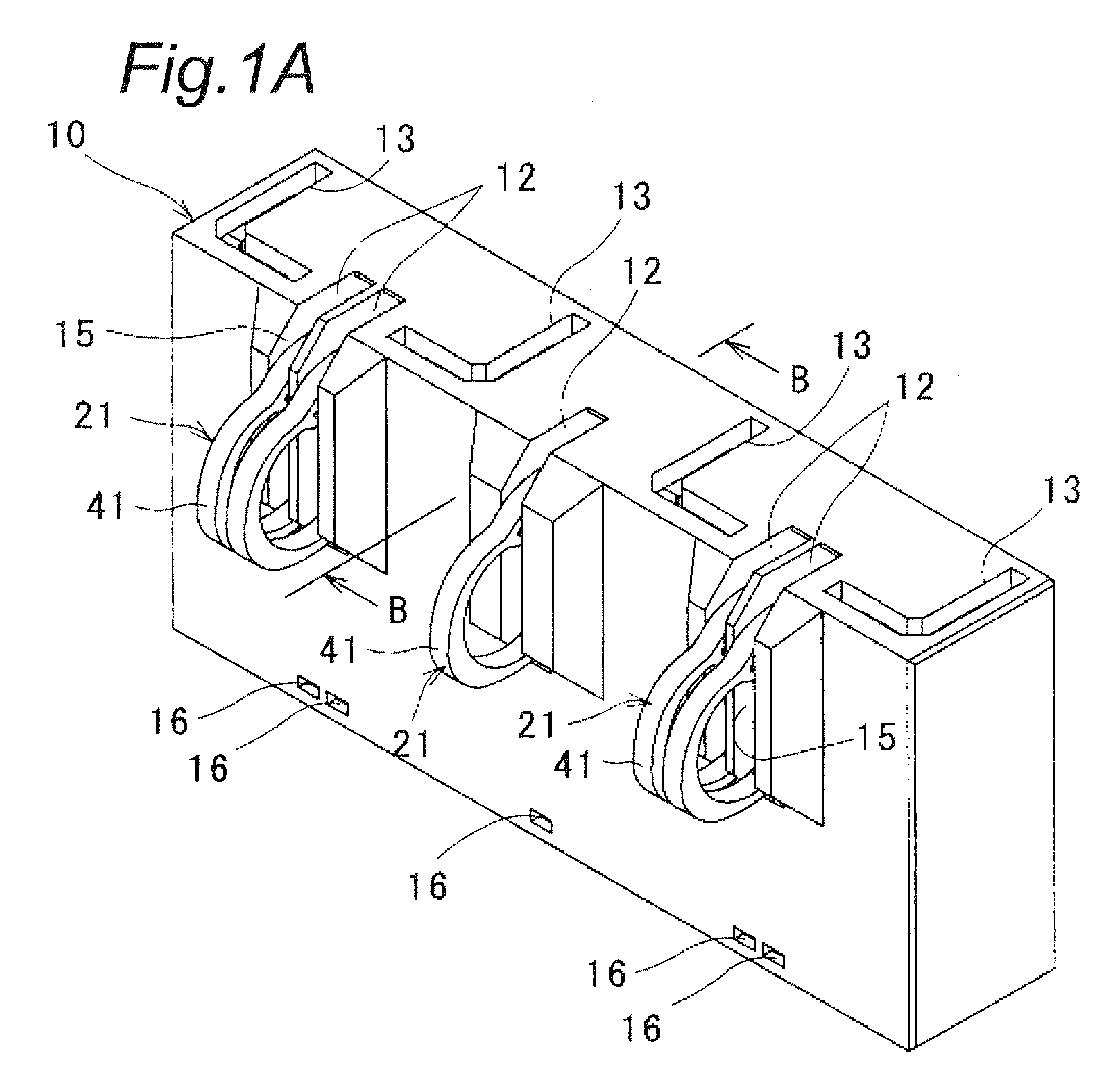
Fig. 1A is a perspective view showing a connector in which connection terminals according to a first embodiment of the present invention is incorporated, andFig. 1B is a sectional perspective view taken along line B-B inFig. 1A . -
Fig. 2A is a perspective view of the connection terminal according to the first embodiment of the invention, andFig. 2B is a side view ofFig. 2A . -
Fig. 3A is a sectional view of the connection terminal according to the first embodiment shown inFigs. 1 before it is operated, andFig. 3B is a sectional view ofFig. 3A after the connection terminal is operated. -
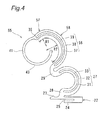
Fig. 4 is a side view of a connection terminal according to a second embodiment of the invention. -
Fig. 5 is a side view of a connection terminal according to a third embodiment of the invention. -
Fig. 6A is a perspective view of a connection terminal according to a fourth embodiment of the invention, andFig. 6B is a side view ofFig. 6A . -
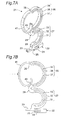
Fig. 7A is a perspective view of the connection terminal according to the fourth embodiment shown inFigs. 6 after it is operated, andFig. 7B is a side view ofFig. 7A . -
Fig. 8A is a sectional view of a connector before it is operated in which the connection terminal according to the fourth embodiment shown inFigs. 6 is incorporated, andFig. 8B is a sectional view ofFig. 8A after the connector is operated. - Embodiments of connection terminals according to the present invention will be described in accordance with accompanying drawings of
Figs. 1 to 5 . - A first embodiment shows a case where
connection terminals 21 are press fitted into a resin-moldedhousing 10 with a predetermined pitch as shown inFigs. 1 to 3 . - As shown
Figs. 1A and 1B , thehousing 10 is provided withaccommodating spaces 12 into whichconnection terminals 21 can be press fitted from a back side of thehousing 10, and throughholes 13 having L-shaped cross sections. Fixing brackets (not shown) having L-shaped cross sections which stand on a substrate are inserted through the through holes 13. A front surface of thehousing 10 is provided withcontact holes 15 which are in communication with theaccommodating spaces 12 and press-fittingholes 16 which are in communication with theaccommodating spaces 12.Movable contacts 41, which will be described later, can move into and out from the contact holes 15. Position-restrictingreceiving portions 18 are formed on lower side inner surfaces of the contact holes 15. - As shown
Figs. 2A and 2B , each of theconnection terminals 21 includes a press-fitting and fixingportion 22 which is fitted into and fixed to thehousing 10, a firstcurved portion 27 and a secondcurved portion 35 which extend from the press-fitting and fixingportion 22, and themovable contact 41 provided on a free end of the secondcurved portion 35. - An engaging
pawl 23 projects from an upper surface of one end of the press-fitting and fixingportions 22 and a lower surface of the other end is provided with aconnection portion 24, thereby forming a press-fittingnotch 25. Since the press-fitting and fixingportion 22 is provided at a base portion of the firstcurved portion 27 which is located farthest from themovable contact 41, theconnection terminal 21 can reliably be fixed to thehousing 10 through the press-fitting and fixingportion 22. - First
curved portion 27 has a substantially arc shape. Asupport portion 28 is formed on one end of the firstcurved portion 27. Thesupport portion 28 projects upward from the press-fitting and fixingportion 22 such that thesupport portion 28 intercrosses with the press-fitting and fixingportion 22. A substantially arc-shaped connectingportion 29 is formed on the other end of the firstcurved portion 27. A wobbling point P of theconnection terminal 21 is provided on a boundary between thesupport portion 28 and the press-fitting and fixingportion 22 when themovable contact 41 is pressed. - It is preferable that the connecting
portion 29 can be regarded as a rigid body with respect to the firstcurved portion 27. If the connectingportion 29 is the rigid body, when an external force is applied to the movable contact 41 (described later), the firstcurved portion 27 is pushed and the curvature is widened. Therefore, it is possible to prevent stress from being concentrated on a specific location, and to prevent theconnection terminal 21 from being plastically deformed. - In order to make the connecting portion 29 a rigid body, it is necessary that a spring constant of the connecting
portion 29 is greater than those of the firstcurved portion 27 and the second curved portion 35 (described later). Especially, to bring the connectingportion 29 closer to an ideal rigid body, it is preferable that the spring constant of the connectingportion 29 is greater than those of the firstcurved portion 27 and the secondcurved portion 35 by a one digit place or more, i.e., more than 10 times. - The first
curved portion 27 includes a first inner extendingportion 31 and a first outer extendingportion 32 which are curved and are bifurcating from thesupport portion 28. Afirst slit 33 is formed between first inner extendingportion 31 and first outer extendingportion 32. The first inner extendingportion 31 and first outer extendingportion 32 are integrally formed together through the connectingportion 29, where thefirst slit 33 terminates. An angle α around a center of curvature measured between an end of the firstcurved portion 27 on the side of thesupport portion 28 and an end of the firstcurved portion 27 on the side of the connectingportion 29 is greater than 180°. - The second
curved portion 35 has an arc shape having a curvature radius greater than that of the firstcurved portion 27. The connectingportion 29 is formed on one of ends of the secondcurved portion 35, and themovable contact 41 is formed the other end of the secondcurved portion 35 on the side of afree end 36. The secondcurved portion 35 includes a second inner extendingportion 37 and a second outer extendingportion 38 which are curved and are bifurcated from the connectingportion 29. Asecond slit 39 is formed between second inner extendingportion 37 and second outer extendingportion 38. The second inner extendingportion 37 and the second outer extendingportion 38 are integrally formed together through thefree end 36, where thesecond slit 39 terminates. - An angle β around a center of curvature measured between an end of the second
curved portion 35 on the side of the connectingportion 29 and an end of the secondcurved portion 35 on the side of thefree end 36 is greater than 180°. Since both the angle α around the center of curvature and the angle β around the center of curvature are greater than 180°, when an external force is applied to themovable contact 41, the firstcurved portion 27 is pushed and the curvature is widened. Hence, it is possible to prevent stress from being concentrated on a specific location, and to prevent theconnection terminal 21 from being plastically deformed. - A straight line L1 connecting between the
free end 36 and the wobbling point P is inclined from a vertical line L2 in a direction towards a point where a load acts. Accordingly, when an external force is applied, it is possible to secure a large shifting distance of themovable contact 41. - Further, since the first
curved portion 27 and the secondcurved portion 35 having openings oriented to the same direction are connected to each other to form substantially a shape of letter "3" through the connectingportion 29, it is possible to form a connection terminal having a small size in depth. Also, it is possible to scatter the stress by thefirst slit 33 and thesecond slit 39 provided in the firstcurved portion 27 and the secondcurved portion 35, respectively. Since the size of the firstcurved portion 27 and that of the secondcurved portion 35 can be made different, it is possible to change displacement amounts of the respective curvature when an external force is applied, and it becomes easy to design the connection terminal in accordance with intended use. The size or the length of the secondcurved portion 35 located on the upper side is greater than that of the firstcurved portion 27 located on the lower side. Hence, when an external force is applied, the deformation amount of the secondcurved portion 35 is greater than that of the firstcurved portion 27. Also, an external force can be propagated to theentire connection terminal 21. The freedom of the design choice is enhanced. - The
movable contact 41 outwardly extends and curves from thefree end 36 of the secondcurved portion 35. Since themovable contact 41 is connected to thefree end 36 of the secondcurved portion 35, contact reliability can be enhanced, and an external force applied to themovable contact 41 can reliably be transmitted to the secondcurved portion 35. Especially when a large impact force is applied from outside, it is possible to scatter the impact force, and to enhance impact resistance. In a state where theconnection terminal 21 is press fitted into and fixed to thehousing 10, themovable contact 41 projects from thecontact hole 15 such that themovable contact 41 can be pressed. Further, a downwardlycurved guide portion 43 extends toward the secondcurved portion 35 from an end of themovable contact 41 opposite from thefree end 36. Since theguide portion 43 extends from a tip end of themovable contact 41 toward the secondcurved portion 35 in this manner, when an external force is applied, themovable contact 41 is guided by theguide portion 43, and themovable contact 41 can reliably move in thecontact hole 15 without being clogged in thecontact hole 15 of thehousing 10. Further, since theguide portion 43 is formed in a curvature, when an external force is applied, theguide portion 43 can turn about a center of its curvature and can move in thecontact hole 15. - It is not necessary that the
movable contact 41 is made separately from the secondcurved portion 35 or theguide portion 43, and themovable contact 41 may share its function with the secondcurved portion 35 or theguide portion 43. In this case, a region which projects from thecontact hole 15, provided that no external force is applied, is called themovable contact 41. - To form the connector through the steps of incorporating each of the
connection terminals 21 into thehousing 10, theconnection terminal 21 is first inserted into theaccommodating space 12 from its back side, and then the press-fitting and fixingportion 22 is press fitted into the press-fittinghole 16 as shown inFig. 3A . The engagingpawl 23 is engaged with an inner surface of the press-fittinghole 16, and theconnection portion 24 is engaged with an edge of thehousing 10, thereby preventing theconnection portion 24 from being pulled out. An outer surface of the connectingportion 29 of theconnection terminal 21 abuts against the position-restrictingreceiving portion 18 of thehousing 10 and a position thereof is restricted. Since the connector is configured using theconnection terminal 21 of the present invention as described above, it is possible to prevent the stress from being concentrated in a narrow spot, and thus obtaining a connector having an excellent durability. - If the
movable contact 41 of the connector mounted on a printed substrate (not shown) is pushed in, the secondcurved portion 35 is pushed and widened and in this state, the secondcurved portion 35 moves toward the back side of thehousing 10 and the second outer extendingportion 38 abuts against aceiling surface 19 as shown inFig. 3B . At the same time, the connectingportion 29 moves away from the position-restrictingreceiving portion 18, and the firstcurved portion 27 is also pushed and widened like the secondcurved portion 35. Since the spring constant of the connectingportion 29 is greater than those of the firstcurved portion 27 and the secondcurved portion 35 by one digit place or more, the connectingportion 29 hardly deforms. - If an external force is applied to the
movable contact 41 and theconnection terminal 21 elastically deforms as described above, both the firstcurved portion 27 and the secondcurved portion 35 are pushed and widened. Hence, it is possible to prevent stress from concentrating on a specific location. According to this, it is possible to prevent theconnection terminal 21 from plastically deforming, and to obtain theconnection terminal 21 having excellent durability. If themovable contact 41 is pushed in, theguide portion 43 moves such that it curls into the secondcurved portion 35. Hence, themovable contact 41 is guided by theguide portion 43 and can reliably move in thecontact hole 15 without being hindered by thecontact hole 15 of thehousing 10. - The present invention is not limited to the above-described embodiment, and the invention can variously be modified.
- As shown in
Fig. 4 , aconnection terminal 55 of a second embodiment has a second curved portion 56 including two arc sections having different curvature radii. For example, a curvature radius R1 of anupper half section 57 of a second curved portion 56 is smaller than a curvature radius R2 of alower half section 58. - Since the second curved portion 56 has the two different curvature radii, when an external force is applied, it is possible to change deformation amounts generated in different sections of the second curved portion 56, and the freedom in design choice is enhanced. Since the curvature radius of the
upper half section 57 is smaller than that of thelower half section 58, when an external force is applied, a deformation amount of the second curved portion 56 on the side of themovable contact 41 is made small and a deformation amount of the second curved portion 56 on the side of the connectingportion 29 is made great, and even when theentire connection terminal 21 receives a large load, it is possible to obtain aconnection terminal 21 having small influence of stress concentration. - As shown in
Fig. 5 aconnection terminal 61 according to a third embodiment has a secondcurved portion 62 including three arc sections having different curvature radii. For example, a curvature radius R3 of anupper half section 63 configuring the secondcurved portion 62 is smaller than a curvature radius R4 of anintermediate section 64, and the curvature radius R4 of theintermediate section 64 is smaller than a curvature radius R5 of alower half section 65. - The curvature radius of the second
curved portion 62 is sequentially increased from themovable contact 41 toward the connectingportion 29. Hence, when an external force is applied, a deformation amount of the secondcurved portion 62 is sequentially increased from themovable contact 41, and it is possible to obtain theconnection terminal 61 having small influence of stress concentration even when theentire connection terminal 61 receives a large load. - A
connection terminal 21 according to a fourth embodiment shown inFigs. 6 to 8 is substantially the same as those of the previous embodiments, but theconnection terminal 21 of the fourth embodiment is different from those of the previous embodiments in that amovable contact 41 is includes two arc sections having different curvature radii R6 and R7. Aguide portion 43 composed of an arc section having a different curvature radius R8 from the rest extends from a free end of themovable contact 41, and theguide portion 43 can abut against a connectingportion 29. Since other configurations are substantially equal to those of the previous embodiments, the same reference signs are allocated to the same members, and description thereof will be omitted. - Next, to form a connector through the steps of incorporating each of the
connection terminals 21 into ahousing 10 , theconnection terminal 21 is inserted into anaccommodating space 12 from a back side thereof, and a press-fitting and fixingportion 22 is press-fitted into a press-fittinghole 16 as shown inFig. 8A . An engagingpawl 23 is engaged with an inner surface of the press-fittinghole 16 and aconnection portion 24 is engaged with an edge of thehousing 10, thereby preventing theconnection portion 24 from being pulled out. An outer surface of a connectingportion 29 of theconnection terminal 21 abuts against a position-restrictingreceiving portion 18 of thehousing 10 and a position thereof is restricted. Since the connector is configured using theconnection terminal 21 of the present invention as described above, it is possible to prevent the stress concentration, and to obtain a connector having excellent durability. - If the
movable contact 41 of the connector mounted on a printed substrate (not shown) is pushed in, themovable contact 41 elastically deforms inward as shown inFig. 8B , a secondcurved portion 35 is pushed and widened and in this state, the secondcurved portion 35 moves toward a back side of thehousing 10 and the connectingportion 29 moves away from the position-restrictingreceiving portion 18. At this time, a firstcurved portion 27 is also pushed and widened like thesecond curvedportion 35. Next, theguide portion 43 abuts against the connectingportion 29 and a second outer extendingportion 38 abuts against aceiling surface 19. Since a spring constant of the connectingportion 29 is greater than those of the firstcurved portion 27, the secondcurved portion 35 and themovable contact 41 by one digit place or more, the connectingportion 29 does not deform almost at all. - As described above, if an external force is applied to the
movable contact 41 and theconnection terminal 21 elastically deforms, both the firstcurved portion 27 and the secondcurved portion 35 are pushed and widened. Furthermore, theguide portion 43 abuts against the connectingportion 29. Hence, it is possible to prevent stress from being concentrated on a specific location. According to this, it is possible to prevent theconnection terminal 21 from being plastically deformed, and to obtain theconnection terminal 21 having excellent durability. - The shapes of the connection terminals according to the present invention are not limited to those described above, and the connection terminals are not especially limited to those described above. Various connection terminals are included as long as they include the curved portions which can be pushed and widened.
- It is possible to employ a curved portion including a plurality of arc sections having different curvature radii.
- When the connection terminal is composed of one curved portion, the guide portion may abut against the base portion of the curved portion. When the connection terminal is composed of a plurality of curved portions, the guide portion may abut against a connecting portion formed between the curved portions.
-
- 10
- housing
- 15
- contact hole
- 16
- press-fitting hole
- 21
- connection terminal
- 22
- press-fitting and fixing portion
- 27
- first curved portion
- 29
- connecting portion
- 31
- first inner extending portion
- 32
- first outer extending portion
- 35
- second curved portion
- 36
- free end
- 37
- second inner extending portion
- 38
- second outer extending portion
- 41
- movable contact
- 43
- guide portion
- 55
- connection terminal
- 56
- second curved portion
- 61
- connection terminal
- 62
- second curved portion
Claims (16)
- A connection terminal comprising:a movable contact which projects outside from a contact hole of a housing such that the movable contact can be pressed, anda curved portion which is pushed and widened by a load applied to the movable contact.
- The connection terminal according to claim 1, further comprising at least two curved portions, wherein
the curved portions are connected to each other through a connecting portion. - The connection terminal according to claim 2, wherein
at least two curved portions are connected to each other through the connecting portion to form substantially a shape of letter "3". - The connection terminal according to claim 2 or 3, wherein
a spring constant of the connecting portion is greater than that of the curved portion. - The connection terminal according to any one of claims 2 to 4, wherein
curvature radii of at least the two curved portions are different from each other. - The connection terminal according to claim 5, wherein
a curvature radius of one of the curved portions placed closest to the movable contact is greater than a curvature radius of the other curved portion. - The connection terminal according to claim 5 or 6, wherein
curvature radii of the curved portions are sequentially reduced from the movable contact. - The connection terminal according to any one of claims 1 to 7, wherein
a straight line connecting between a free end and a wobbling point is inclined toward a load. - The connection terminal according to any one of claims 1 to 8, wherein
the curved portion includes a slit formed by a plurality of extending portions. - The connection terminal according to any one of claims 1 to 9, wherein
the movable contact is connected to a free end of the curved portion. - The connection terminal according to any one of claims 1 to 10, further comprising:a guide portion which extends from a tip end of the movable contact and curves toward the curved portion.
- The connection terminal according to claim 11, wherein
when the movable contact is pressed, the guide portion moves toward the curved portion. - The connection terminal according to any one of claims 1 to 12, wherein
the curved portion includes a plurality of arc sections having different curvature radii. - The connection terminal according to any one of claims 1 to 13, further comprising:a base portion of the curved portion which is located farthest from the movable contact; anda press-fitting and fixing portion formed at the base portion for the connection with the housing.
- The connection terminal according to any one of claims 1 to 14, wherein
the guide portion has such a shape that when the movable contact is pressed, the guide portion abuts against a base portion of the curved portion. - A connector wherein
the press-fitting and fixing portion of the connection terminal according to any one of claims 1 to 15 is press fitted into and fixed to a press-fitting hole of the housing, and the movable contact projects from a contact hole provided in the housing such that the movable contact can move into and out from the contact hole.
Applications Claiming Priority (2)
| Application Number | Priority Date | Filing Date | Title |
|---|---|---|---|
| JP2012059297 | 2012-03-15 | ||
| PCT/JP2013/057254 WO2013137406A1 (en) | 2012-03-15 | 2013-03-14 | Connection terminal and connector using same |
Publications (3)
| Publication Number | Publication Date |
|---|---|
| EP2827456A1 true EP2827456A1 (en) | 2015-01-21 |
| EP2827456A4 EP2827456A4 (en) | 2015-10-14 |
| EP2827456B1 EP2827456B1 (en) | 2019-09-04 |
Family
ID=49161309
Family Applications (1)
| Application Number | Title | Priority Date | Filing Date |
|---|---|---|---|
| EP13761500.1A Active EP2827456B1 (en) | 2012-03-15 | 2013-03-14 | Connection terminal and connector using same |
Country Status (5)
| Country | Link |
|---|---|
| US (1) | US9368893B2 (en) |
| EP (1) | EP2827456B1 (en) |
| JP (1) | JP5812187B2 (en) |
| CN (1) | CN104170175B (en) |
| WO (1) | WO2013137406A1 (en) |
Families Citing this family (6)
| Publication number | Priority date | Publication date | Assignee | Title |
|---|---|---|---|---|
| DE59611381D1 (en) | 1995-03-18 | 2006-10-12 | Koenig & Bauer Ag | Drive a folder of a rotary printing press |
| US9368893B2 (en) * | 2012-03-15 | 2016-06-14 | Omron Corporation | Connection terminal and connector using same |
| JP6991782B2 (en) * | 2017-08-23 | 2022-01-13 | センサータ テクノロジーズ インコーポレーテッド | socket |
| TWM602744U (en) * | 2020-01-20 | 2020-10-11 | 唐虞企業股份有限公司 | Forced mechanism and connector constituted of the same |
| WO2024011607A1 (en) * | 2022-07-15 | 2024-01-18 | 珠海领翌科技有限公司 | Connector and elastic contact |
| CN116014508B (en) * | 2023-03-27 | 2023-06-09 | 深圳市西点精工技术有限公司 | Full-shielding high-speed connector |
Family Cites Families (12)
| Publication number | Priority date | Publication date | Assignee | Title |
|---|---|---|---|---|
| US4494807A (en) * | 1982-12-27 | 1985-01-22 | Amp Incorporated | Low profile chip carrier contact |
| JP2000323216A (en) * | 1999-05-07 | 2000-11-24 | Kyoshin Kogyo Co Ltd | Connection terminal and taping connection terminal |
| JP4199897B2 (en) | 2000-02-23 | 2008-12-24 | 株式会社秩父富士 | IC socket contact |
| US6290524B1 (en) * | 2000-07-12 | 2001-09-18 | Molex Incorporated | System for varying capacitive coupling between electrical terminals |
| JP2008276987A (en) | 2007-04-25 | 2008-11-13 | Tyco Electronics Amp Kk | Contact and electrical connector |
| CN101047288A (en) * | 2007-04-28 | 2007-10-03 | 博罗立峰开关实业有限公司 | Battery spring lamination module |
| JP5103566B2 (en) * | 2007-11-26 | 2012-12-19 | 株式会社コーヨーテクノス | Electrical contact and inspection jig having the same |
| CN201303183Y (en) * | 2008-11-03 | 2009-09-02 | 富士康(昆山)电脑接插件有限公司 | Electric connector |
| JP5540718B2 (en) * | 2010-01-15 | 2014-07-02 | オムロン株式会社 | Electrical connector, electronic device, and conductive contact method |
| JP4883215B1 (en) * | 2010-10-29 | 2012-02-22 | オムロン株式会社 | Terminal and connector using the same |
| JP4811530B1 (en) * | 2010-11-04 | 2011-11-09 | オムロン株式会社 | Terminal and connector using the same |
| US9368893B2 (en) * | 2012-03-15 | 2016-06-14 | Omron Corporation | Connection terminal and connector using same |
-
2013
- 2013-03-14 US US14/384,346 patent/US9368893B2/en active Active
- 2013-03-14 EP EP13761500.1A patent/EP2827456B1/en active Active
- 2013-03-14 CN CN201380012894.XA patent/CN104170175B/en active Active
- 2013-03-14 WO PCT/JP2013/057254 patent/WO2013137406A1/en not_active Ceased
- 2013-03-14 JP JP2014505002A patent/JP5812187B2/en not_active Expired - Fee Related
Also Published As
| Publication number | Publication date |
|---|---|
| WO2013137406A1 (en) | 2013-09-19 |
| CN104170175A (en) | 2014-11-26 |
| JPWO2013137406A1 (en) | 2015-08-03 |
| JP5812187B2 (en) | 2015-11-11 |
| US9368893B2 (en) | 2016-06-14 |
| US20150031234A1 (en) | 2015-01-29 |
| EP2827456B1 (en) | 2019-09-04 |
| EP2827456A4 (en) | 2015-10-14 |
| CN104170175B (en) | 2017-03-08 |
Similar Documents
| Publication | Publication Date | Title |
|---|---|---|
| EP2827456B1 (en) | Connection terminal and connector using same | |
| CN102742087B (en) | Terminals and connectors using them | |
| CN104659512B (en) | Pin contact for an electrical connector | |
| CN104425936B (en) | Connector | |
| JP4883215B1 (en) | Terminal and connector using the same | |
| EP1786065B1 (en) | A terminal fitting and a connector provided therewith | |
| EP2642606A1 (en) | Connector unit | |
| CN104425919B (en) | Connector | |
| JP2007324029A (en) | Electrical connection terminal and connector using the same | |
| TWI532265B (en) | Connection terminal and connector using the same | |
| JP2015026502A (en) | Electric connector and substrate unit | |
| ES2906898T3 (en) | Contact Element Arrangement | |
| CN104170176B (en) | Connection terminals and connectors using connection terminals | |
| JP2009170331A (en) | Connecting terminal | |
| CN106169668B (en) | Connector | |
| US9425523B2 (en) | Electrical connector with contact pin shoulders | |
| KR101520927B1 (en) | Terminal |
Legal Events
| Date | Code | Title | Description |
|---|---|---|---|
| PUAI | Public reference made under article 153(3) epc to a published international application that has entered the european phase |
Free format text: ORIGINAL CODE: 0009012 |
|
| 17P | Request for examination filed |
Effective date: 20141002 |
|
| AK | Designated contracting states |
Kind code of ref document: A1 Designated state(s): AL AT BE BG CH CY CZ DE DK EE ES FI FR GB GR HR HU IE IS IT LI LT LU LV MC MK MT NL NO PL PT RO RS SE SI SK SM TR |
|
| AX | Request for extension of the european patent |
Extension state: BA ME |
|
| DAX | Request for extension of the european patent (deleted) | ||
| RA4 | Supplementary search report drawn up and despatched (corrected) |
Effective date: 20150915 |
|
| RIC1 | Information provided on ipc code assigned before grant |
Ipc: H01R 13/24 20060101AFI20150909BHEP Ipc: H01R 33/76 20060101ALI20150909BHEP Ipc: H01R 12/57 20110101ALN20150909BHEP Ipc: H05K 7/10 20060101ALN20150909BHEP Ipc: H01R 13/11 20060101ALI20150909BHEP |
|
| STAA | Information on the status of an ep patent application or granted ep patent |
Free format text: STATUS: EXAMINATION IS IN PROGRESS |
|
| 17Q | First examination report despatched |
Effective date: 20170405 |
|
| GRAP | Despatch of communication of intention to grant a patent |
Free format text: ORIGINAL CODE: EPIDOSNIGR1 |
|
| STAA | Information on the status of an ep patent application or granted ep patent |
Free format text: STATUS: GRANT OF PATENT IS INTENDED |
|
| RIC1 | Information provided on ipc code assigned before grant |
Ipc: H05K 7/10 20060101ALN20190305BHEP Ipc: H01R 13/24 20060101AFI20190305BHEP Ipc: H01R 33/76 20060101ALI20190305BHEP Ipc: H01R 12/57 20110101ALN20190305BHEP Ipc: H01R 13/11 20060101ALI20190305BHEP |
|
| INTG | Intention to grant announced |
Effective date: 20190325 |
|
| GRAS | Grant fee paid |
Free format text: ORIGINAL CODE: EPIDOSNIGR3 |
|
| GRAA | (expected) grant |
Free format text: ORIGINAL CODE: 0009210 |
|
| STAA | Information on the status of an ep patent application or granted ep patent |
Free format text: STATUS: THE PATENT HAS BEEN GRANTED |
|
| AK | Designated contracting states |
Kind code of ref document: B1 Designated state(s): AL AT BE BG CH CY CZ DE DK EE ES FI FR GB GR HR HU IE IS IT LI LT LU LV MC MK MT NL NO PL PT RO RS SE SI SK SM TR |
|
| REG | Reference to a national code |
Ref country code: GB Ref legal event code: FG4D |
|
| REG | Reference to a national code |
Ref country code: CH Ref legal event code: EP |
|
| REG | Reference to a national code |
Ref country code: AT Ref legal event code: REF Ref document number: 1176685 Country of ref document: AT Kind code of ref document: T Effective date: 20190915 |
|
| REG | Reference to a national code |
Ref country code: DE Ref legal event code: R096 Ref document number: 602013060056 Country of ref document: DE |
|
| REG | Reference to a national code |
Ref country code: IE Ref legal event code: FG4D |
|
| REG | Reference to a national code |
Ref country code: NL Ref legal event code: MP Effective date: 20190904 |
|
| REG | Reference to a national code |
Ref country code: LT Ref legal event code: MG4D |
|
| PG25 | Lapsed in a contracting state [announced via postgrant information from national office to epo] |
Ref country code: NO Free format text: LAPSE BECAUSE OF FAILURE TO SUBMIT A TRANSLATION OF THE DESCRIPTION OR TO PAY THE FEE WITHIN THE PRESCRIBED TIME-LIMIT Effective date: 20191204 Ref country code: LT Free format text: LAPSE BECAUSE OF FAILURE TO SUBMIT A TRANSLATION OF THE DESCRIPTION OR TO PAY THE FEE WITHIN THE PRESCRIBED TIME-LIMIT Effective date: 20190904 Ref country code: BG Free format text: LAPSE BECAUSE OF FAILURE TO SUBMIT A TRANSLATION OF THE DESCRIPTION OR TO PAY THE FEE WITHIN THE PRESCRIBED TIME-LIMIT Effective date: 20191204 Ref country code: FI Free format text: LAPSE BECAUSE OF FAILURE TO SUBMIT A TRANSLATION OF THE DESCRIPTION OR TO PAY THE FEE WITHIN THE PRESCRIBED TIME-LIMIT Effective date: 20190904 Ref country code: HR Free format text: LAPSE BECAUSE OF FAILURE TO SUBMIT A TRANSLATION OF THE DESCRIPTION OR TO PAY THE FEE WITHIN THE PRESCRIBED TIME-LIMIT Effective date: 20190904 Ref country code: SE Free format text: LAPSE BECAUSE OF FAILURE TO SUBMIT A TRANSLATION OF THE DESCRIPTION OR TO PAY THE FEE WITHIN THE PRESCRIBED TIME-LIMIT Effective date: 20190904 |
|
| PG25 | Lapsed in a contracting state [announced via postgrant information from national office to epo] |
Ref country code: ES Free format text: LAPSE BECAUSE OF FAILURE TO SUBMIT A TRANSLATION OF THE DESCRIPTION OR TO PAY THE FEE WITHIN THE PRESCRIBED TIME-LIMIT Effective date: 20190904 Ref country code: GR Free format text: LAPSE BECAUSE OF FAILURE TO SUBMIT A TRANSLATION OF THE DESCRIPTION OR TO PAY THE FEE WITHIN THE PRESCRIBED TIME-LIMIT Effective date: 20191205 Ref country code: AL Free format text: LAPSE BECAUSE OF FAILURE TO SUBMIT A TRANSLATION OF THE DESCRIPTION OR TO PAY THE FEE WITHIN THE PRESCRIBED TIME-LIMIT Effective date: 20190904 Ref country code: RS Free format text: LAPSE BECAUSE OF FAILURE TO SUBMIT A TRANSLATION OF THE DESCRIPTION OR TO PAY THE FEE WITHIN THE PRESCRIBED TIME-LIMIT Effective date: 20190904 Ref country code: LV Free format text: LAPSE BECAUSE OF FAILURE TO SUBMIT A TRANSLATION OF THE DESCRIPTION OR TO PAY THE FEE WITHIN THE PRESCRIBED TIME-LIMIT Effective date: 20190904 |
|
| REG | Reference to a national code |
Ref country code: AT Ref legal event code: MK05 Ref document number: 1176685 Country of ref document: AT Kind code of ref document: T Effective date: 20190904 |
|
| PG25 | Lapsed in a contracting state [announced via postgrant information from national office to epo] |
Ref country code: IT Free format text: LAPSE BECAUSE OF FAILURE TO SUBMIT A TRANSLATION OF THE DESCRIPTION OR TO PAY THE FEE WITHIN THE PRESCRIBED TIME-LIMIT Effective date: 20190904 Ref country code: AT Free format text: LAPSE BECAUSE OF FAILURE TO SUBMIT A TRANSLATION OF THE DESCRIPTION OR TO PAY THE FEE WITHIN THE PRESCRIBED TIME-LIMIT Effective date: 20190904 Ref country code: EE Free format text: LAPSE BECAUSE OF FAILURE TO SUBMIT A TRANSLATION OF THE DESCRIPTION OR TO PAY THE FEE WITHIN THE PRESCRIBED TIME-LIMIT Effective date: 20190904 Ref country code: RO Free format text: LAPSE BECAUSE OF FAILURE TO SUBMIT A TRANSLATION OF THE DESCRIPTION OR TO PAY THE FEE WITHIN THE PRESCRIBED TIME-LIMIT Effective date: 20190904 Ref country code: NL Free format text: LAPSE BECAUSE OF FAILURE TO SUBMIT A TRANSLATION OF THE DESCRIPTION OR TO PAY THE FEE WITHIN THE PRESCRIBED TIME-LIMIT Effective date: 20190904 Ref country code: PL Free format text: LAPSE BECAUSE OF FAILURE TO SUBMIT A TRANSLATION OF THE DESCRIPTION OR TO PAY THE FEE WITHIN THE PRESCRIBED TIME-LIMIT Effective date: 20190904 Ref country code: PT Free format text: LAPSE BECAUSE OF FAILURE TO SUBMIT A TRANSLATION OF THE DESCRIPTION OR TO PAY THE FEE WITHIN THE PRESCRIBED TIME-LIMIT Effective date: 20200106 |
|
| PG25 | Lapsed in a contracting state [announced via postgrant information from national office to epo] |
Ref country code: IS Free format text: LAPSE BECAUSE OF FAILURE TO SUBMIT A TRANSLATION OF THE DESCRIPTION OR TO PAY THE FEE WITHIN THE PRESCRIBED TIME-LIMIT Effective date: 20200224 Ref country code: SK Free format text: LAPSE BECAUSE OF FAILURE TO SUBMIT A TRANSLATION OF THE DESCRIPTION OR TO PAY THE FEE WITHIN THE PRESCRIBED TIME-LIMIT Effective date: 20190904 Ref country code: CZ Free format text: LAPSE BECAUSE OF FAILURE TO SUBMIT A TRANSLATION OF THE DESCRIPTION OR TO PAY THE FEE WITHIN THE PRESCRIBED TIME-LIMIT Effective date: 20190904 Ref country code: SM Free format text: LAPSE BECAUSE OF FAILURE TO SUBMIT A TRANSLATION OF THE DESCRIPTION OR TO PAY THE FEE WITHIN THE PRESCRIBED TIME-LIMIT Effective date: 20190904 |
|
| REG | Reference to a national code |
Ref country code: DE Ref legal event code: R097 Ref document number: 602013060056 Country of ref document: DE |
|
| PLBE | No opposition filed within time limit |
Free format text: ORIGINAL CODE: 0009261 |
|
| STAA | Information on the status of an ep patent application or granted ep patent |
Free format text: STATUS: NO OPPOSITION FILED WITHIN TIME LIMIT |
|
| PG2D | Information on lapse in contracting state deleted |
Ref country code: IS |
|
| PG25 | Lapsed in a contracting state [announced via postgrant information from national office to epo] |
Ref country code: DK Free format text: LAPSE BECAUSE OF FAILURE TO SUBMIT A TRANSLATION OF THE DESCRIPTION OR TO PAY THE FEE WITHIN THE PRESCRIBED TIME-LIMIT Effective date: 20190904 Ref country code: IS Free format text: LAPSE BECAUSE OF FAILURE TO SUBMIT A TRANSLATION OF THE DESCRIPTION OR TO PAY THE FEE WITHIN THE PRESCRIBED TIME-LIMIT Effective date: 20200105 |
|
| 26N | No opposition filed |
Effective date: 20200605 |
|
| PG25 | Lapsed in a contracting state [announced via postgrant information from national office to epo] |
Ref country code: SI Free format text: LAPSE BECAUSE OF FAILURE TO SUBMIT A TRANSLATION OF THE DESCRIPTION OR TO PAY THE FEE WITHIN THE PRESCRIBED TIME-LIMIT Effective date: 20190904 |
|
| PG25 | Lapsed in a contracting state [announced via postgrant information from national office to epo] |
Ref country code: MC Free format text: LAPSE BECAUSE OF FAILURE TO SUBMIT A TRANSLATION OF THE DESCRIPTION OR TO PAY THE FEE WITHIN THE PRESCRIBED TIME-LIMIT Effective date: 20190904 |
|
| REG | Reference to a national code |
Ref country code: CH Ref legal event code: PL |
|
| REG | Reference to a national code |
Ref country code: BE Ref legal event code: MM Effective date: 20200331 |
|
| PG25 | Lapsed in a contracting state [announced via postgrant information from national office to epo] |
Ref country code: LU Free format text: LAPSE BECAUSE OF NON-PAYMENT OF DUE FEES Effective date: 20200314 |
|
| PG25 | Lapsed in a contracting state [announced via postgrant information from national office to epo] |
Ref country code: LI Free format text: LAPSE BECAUSE OF NON-PAYMENT OF DUE FEES Effective date: 20200331 Ref country code: IE Free format text: LAPSE BECAUSE OF NON-PAYMENT OF DUE FEES Effective date: 20200314 Ref country code: CH Free format text: LAPSE BECAUSE OF NON-PAYMENT OF DUE FEES Effective date: 20200331 Ref country code: FR Free format text: LAPSE BECAUSE OF NON-PAYMENT OF DUE FEES Effective date: 20200331 |
|
| PG25 | Lapsed in a contracting state [announced via postgrant information from national office to epo] |
Ref country code: BE Free format text: LAPSE BECAUSE OF NON-PAYMENT OF DUE FEES Effective date: 20200331 |
|
| GBPC | Gb: european patent ceased through non-payment of renewal fee |
Effective date: 20200314 |
|
| PG25 | Lapsed in a contracting state [announced via postgrant information from national office to epo] |
Ref country code: GB Free format text: LAPSE BECAUSE OF NON-PAYMENT OF DUE FEES Effective date: 20200314 |
|
| PG25 | Lapsed in a contracting state [announced via postgrant information from national office to epo] |
Ref country code: TR Free format text: LAPSE BECAUSE OF FAILURE TO SUBMIT A TRANSLATION OF THE DESCRIPTION OR TO PAY THE FEE WITHIN THE PRESCRIBED TIME-LIMIT Effective date: 20190904 Ref country code: MT Free format text: LAPSE BECAUSE OF FAILURE TO SUBMIT A TRANSLATION OF THE DESCRIPTION OR TO PAY THE FEE WITHIN THE PRESCRIBED TIME-LIMIT Effective date: 20190904 Ref country code: CY Free format text: LAPSE BECAUSE OF FAILURE TO SUBMIT A TRANSLATION OF THE DESCRIPTION OR TO PAY THE FEE WITHIN THE PRESCRIBED TIME-LIMIT Effective date: 20190904 |
|
| PG25 | Lapsed in a contracting state [announced via postgrant information from national office to epo] |
Ref country code: MK Free format text: LAPSE BECAUSE OF FAILURE TO SUBMIT A TRANSLATION OF THE DESCRIPTION OR TO PAY THE FEE WITHIN THE PRESCRIBED TIME-LIMIT Effective date: 20190904 |
|
| PGFP | Annual fee paid to national office [announced via postgrant information from national office to epo] |
Ref country code: DE Payment date: 20250319 Year of fee payment: 13 |