EP2827407A1 - Lithium-ion rechargeable battery - Google Patents
Lithium-ion rechargeable battery Download PDFInfo
- Publication number
- EP2827407A1 EP2827407A1 EP13760303.1A EP13760303A EP2827407A1 EP 2827407 A1 EP2827407 A1 EP 2827407A1 EP 13760303 A EP13760303 A EP 13760303A EP 2827407 A1 EP2827407 A1 EP 2827407A1
- Authority
- EP
- European Patent Office
- Prior art keywords
- negative electrode
- positive electrode
- ion secondary
- temperature
- lithium ion
- Prior art date
- Legal status (The legal status is an assumption and is not a legal conclusion. Google has not performed a legal analysis and makes no representation as to the accuracy of the status listed.)
- Granted
Links
Images


Classifications
-
- H—ELECTRICITY
- H01—ELECTRIC ELEMENTS
- H01M—PROCESSES OR MEANS, e.g. BATTERIES, FOR THE DIRECT CONVERSION OF CHEMICAL ENERGY INTO ELECTRICAL ENERGY
- H01M10/00—Secondary cells; Manufacture thereof
- H01M10/60—Heating or cooling; Temperature control
- H01M10/63—Control systems
- H01M10/637—Control systems characterised by the use of reversible temperature-sensitive devices, e.g. NTC, PTC or bimetal devices; characterised by control of the internal current flowing through the cells, e.g. by switching
-
- H—ELECTRICITY
- H01—ELECTRIC ELEMENTS
- H01M—PROCESSES OR MEANS, e.g. BATTERIES, FOR THE DIRECT CONVERSION OF CHEMICAL ENERGY INTO ELECTRICAL ENERGY
- H01M10/00—Secondary cells; Manufacture thereof
- H01M10/05—Accumulators with non-aqueous electrolyte
- H01M10/052—Li-accumulators
- H01M10/0525—Rocking-chair batteries, i.e. batteries with lithium insertion or intercalation in both electrodes; Lithium-ion batteries
-
- H—ELECTRICITY
- H01—ELECTRIC ELEMENTS
- H01M—PROCESSES OR MEANS, e.g. BATTERIES, FOR THE DIRECT CONVERSION OF CHEMICAL ENERGY INTO ELECTRICAL ENERGY
- H01M10/00—Secondary cells; Manufacture thereof
- H01M10/05—Accumulators with non-aqueous electrolyte
- H01M10/056—Accumulators with non-aqueous electrolyte characterised by the materials used as electrolytes, e.g. mixed inorganic/organic electrolytes
- H01M10/0564—Accumulators with non-aqueous electrolyte characterised by the materials used as electrolytes, e.g. mixed inorganic/organic electrolytes the electrolyte being constituted of organic materials only
- H01M10/0566—Liquid materials
-
- H—ELECTRICITY
- H01—ELECTRIC ELEMENTS
- H01M—PROCESSES OR MEANS, e.g. BATTERIES, FOR THE DIRECT CONVERSION OF CHEMICAL ENERGY INTO ELECTRICAL ENERGY
- H01M10/00—Secondary cells; Manufacture thereof
- H01M10/05—Accumulators with non-aqueous electrolyte
- H01M10/058—Construction or manufacture
- H01M10/0587—Construction or manufacture of accumulators having only wound construction elements, i.e. wound positive electrodes, wound negative electrodes and wound separators
-
- H—ELECTRICITY
- H01—ELECTRIC ELEMENTS
- H01M—PROCESSES OR MEANS, e.g. BATTERIES, FOR THE DIRECT CONVERSION OF CHEMICAL ENERGY INTO ELECTRICAL ENERGY
- H01M10/00—Secondary cells; Manufacture thereof
- H01M10/42—Methods or arrangements for servicing or maintenance of secondary cells or secondary half-cells
- H01M10/48—Accumulators combined with arrangements for measuring, testing or indicating the condition of cells, e.g. the level or density of the electrolyte
- H01M10/486—Accumulators combined with arrangements for measuring, testing or indicating the condition of cells, e.g. the level or density of the electrolyte for measuring temperature
-
- H—ELECTRICITY
- H01—ELECTRIC ELEMENTS
- H01M—PROCESSES OR MEANS, e.g. BATTERIES, FOR THE DIRECT CONVERSION OF CHEMICAL ENERGY INTO ELECTRICAL ENERGY
- H01M50/00—Constructional details or processes of manufacture of the non-active parts of electrochemical cells other than fuel cells, e.g. hybrid cells
- H01M50/50—Current conducting connections for cells or batteries
- H01M50/572—Means for preventing undesired use or discharge
- H01M50/574—Devices or arrangements for the interruption of current
- H01M50/581—Devices or arrangements for the interruption of current in response to temperature
-
- H—ELECTRICITY
- H01—ELECTRIC ELEMENTS
- H01M—PROCESSES OR MEANS, e.g. BATTERIES, FOR THE DIRECT CONVERSION OF CHEMICAL ENERGY INTO ELECTRICAL ENERGY
- H01M10/00—Secondary cells; Manufacture thereof
- H01M10/05—Accumulators with non-aqueous electrolyte
- H01M10/052—Li-accumulators
-
- H—ELECTRICITY
- H01—ELECTRIC ELEMENTS
- H01M—PROCESSES OR MEANS, e.g. BATTERIES, FOR THE DIRECT CONVERSION OF CHEMICAL ENERGY INTO ELECTRICAL ENERGY
- H01M2200/00—Safety devices for primary or secondary batteries
- H01M2200/10—Temperature sensitive devices
-
- H—ELECTRICITY
- H01—ELECTRIC ELEMENTS
- H01M—PROCESSES OR MEANS, e.g. BATTERIES, FOR THE DIRECT CONVERSION OF CHEMICAL ENERGY INTO ELECTRICAL ENERGY
- H01M2200/00—Safety devices for primary or secondary batteries
- H01M2200/10—Temperature sensitive devices
- H01M2200/103—Fuse
-
- H—ELECTRICITY
- H01—ELECTRIC ELEMENTS
- H01M—PROCESSES OR MEANS, e.g. BATTERIES, FOR THE DIRECT CONVERSION OF CHEMICAL ENERGY INTO ELECTRICAL ENERGY
- H01M2220/00—Batteries for particular applications
- H01M2220/20—Batteries in motive systems, e.g. vehicle, ship, plane
-
- H—ELECTRICITY
- H02—GENERATION; CONVERSION OR DISTRIBUTION OF ELECTRIC POWER
- H02J—ELECTRIC POWER NETWORKS; CIRCUIT ARRANGEMENTS OR SYSTEMS FOR SUPPLYING OR DISTRIBUTING ELECTRIC POWER; SYSTEMS FOR STORING ELECTRIC ENERGY
- H02J7/00—Circuit arrangements for charging or discharging batteries or for supplying loads from batteries
- H02J7/60—Circuit arrangements for charging or discharging batteries or for supplying loads from batteries including safety or protection arrangements
- H02J7/61—Circuit arrangements for charging or discharging batteries or for supplying loads from batteries including safety or protection arrangements against overcharge
-
- Y—GENERAL TAGGING OF NEW TECHNOLOGICAL DEVELOPMENTS; GENERAL TAGGING OF CROSS-SECTIONAL TECHNOLOGIES SPANNING OVER SEVERAL SECTIONS OF THE IPC; TECHNICAL SUBJECTS COVERED BY FORMER USPC CROSS-REFERENCE ART COLLECTIONS [XRACs] AND DIGESTS
- Y02—TECHNOLOGIES OR APPLICATIONS FOR MITIGATION OR ADAPTATION AGAINST CLIMATE CHANGE
- Y02E—REDUCTION OF GREENHOUSE GAS [GHG] EMISSIONS, RELATED TO ENERGY GENERATION, TRANSMISSION OR DISTRIBUTION
- Y02E60/00—Enabling technologies; Technologies with a potential or indirect contribution to GHG emissions mitigation
- Y02E60/10—Energy storage using batteries
-
- Y—GENERAL TAGGING OF NEW TECHNOLOGICAL DEVELOPMENTS; GENERAL TAGGING OF CROSS-SECTIONAL TECHNOLOGIES SPANNING OVER SEVERAL SECTIONS OF THE IPC; TECHNICAL SUBJECTS COVERED BY FORMER USPC CROSS-REFERENCE ART COLLECTIONS [XRACs] AND DIGESTS
- Y02—TECHNOLOGIES OR APPLICATIONS FOR MITIGATION OR ADAPTATION AGAINST CLIMATE CHANGE
- Y02P—CLIMATE CHANGE MITIGATION TECHNOLOGIES IN THE PRODUCTION OR PROCESSING OF GOODS
- Y02P70/00—Climate change mitigation technologies in the production process for final industrial or consumer products
- Y02P70/50—Manufacturing or production processes characterised by the final manufactured product
Definitions
- Embodiments described herein relate generally to a lithium ion secondary battery.
- the secondary batteries are required to be high in output power, high in energy density, reduced in size and weight, low in price, or the like, and the improvement in safety and durability is also indispensable for the secondary batteries.
- Lithium ion secondary batteries are known as high energy-density secondary batteries for automobiles.
- the high energy-density lithium ion secondary battery typically has an electrode assembly obtained by rolling up a positive electrode and a negative electrode stacked with a separator interposed therebetween, impregnated with an organic electrolyte solution, and enclosed in a battery can.
- a heat generation unit is allowed to generate heat in the case of overcharge, and the container is opened with the heat to release gas during the overcharge.
- Patent Literature 1 Japanese Patent Application Laid-Open No. 2006-185708
- the embodiments are aimed at achieving a highly reliable battery which ensure that overcharge conditions can be prevented without any harmful effects on the outside.
- a lithium ion secondary battery has: an electrode assembly formed by rolling up a positive electrode, a separator, and a negative electrode; an organic electrolyte solution; a positive electrode tab connected to the positive electrode; a negative electrode tab connected to the negative electrode; and an overcharge prevention mechanism, which are incorporated in a battery can sealed with a cap body, and includes: a positive electrode terminal fixed to the cap body, and connected to the positive electrode tab; and a negative electrode terminal fixed to the cap body and connected to the negative electrode tab, wherein the overcharge prevention mechanism includes: a temperature-sensitive deformation member configured to detect the internal temperature of the electrode assembly to undergo shape change; a switch member configured to be driven by the shape change of the temperature-sensitive deformation member; a fuse member connected in series between the positive electrode terminal and the positive electrode or the negative electrode terminal and the negative electrode; and a short circuit configured to connect the electrode assembly, the fuse member, and the switch member of the lithium ion secondary battery, and when the switch member is driven and turned on by the shape change of the temperature
- a lithium ion secondary battery has: an electrode assembly formed by rolling up a positive electrode, a separator, and a negative electrode; an organic electrolyte solution; a positive electrode tab connected to the positive electrode; a negative electrode tab connected to the negative electrode; and an overcharge prevention mechanism, which are incorporated in a battery can sealed with a cap body, and includes: a positive electrode terminal fixed to the cap body, and connected to the positive electrode tab; and a negative electrode terminal fixed to the cap body and connected to the negative electrode tab.
- the overcharge prevention mechanism includes: a temperature-sensitive deformation member configured to detect the internal temperature of the electrode assembly to undergo shape change; a switch member configured to be driven by the shape change of the temperature-sensitive deformation member; a fuse member connected in series between the positive electrode terminal and the positive electrode or the negative electrode terminal and the negative electrode; and a short circuit configured to connect the electrode assembly, the fuse member, and the switch member of the lithium ion secondary battery.
- the overcharge prevention mechanism In the operation of the overcharge prevention mechanism, in the case of battery overcharge, the battery body undergoes an increase in temperature, as a result, the temperature-sensitive deformation member undergoes a shape change, and a push rod provided in contact with the temperature-sensitive deformation member pushes the switch member to turn on the switch member. As a result, the short circuit becomes a closed circuit, and the fuse member is melted down by electrical energy accumulated in the electrode assembly, to shut off the charging current path.
- the temperature-sensitive deformation member is preferably composed of at least one of a shape-memory alloy, a bimetal, and a wax.
- the member is further preferably a shape-memory alloy.
- the shape of the shape-memory alloy is preferably a C-shaped ring.
- the short circuit is preferably partially routed through the battery can.
- the fuse member can be composed of a thin part formed on the positive electrode lead or negative electrode lead.
- the switch member includes: a switch unit composed of a lead-like member opposed to the battery can and the battery can; a spring placed near the lead-like member; a spring locking member; and a push rod-like member configured to push out the spring locking member, the spring is compressively fixed by the locking member, in the case of overcharge, the compression of the spring is released in association with the movement of the push rod-like member depending on a deformation of the temperature-sensitive deformation member, and the repulsion force of the spring instantaneously brings the lead-like member and the battery can into contact with each other to close the short circuit, and melt down the fuse member.
- Figure 1 illustrates, in the partially cutaway perspective view therein, a structure example of the lithium ion secondary battery according to the present embodiment.
- the battery 10 includes a battery can 11 in the shape of a hollow circular cylinder with a bottom, a hollow cuboid with a bottom, or a hollow cube with a bottom, which includes an opening, and the opening includes a cap body 18 placed for sealing the opening.
- This cap body 18 is provided with terminals 15, 16 for electric current extraction, which are connected to a positive electrode 12 and a negative electrode 13 inside via electrode leads 22, 23 such as aluminum foil.
- the positive electrode 12 and the negative electrode 13 are formed by applying a positive electrode active material and a negative electrode active material respectively on surfaces of thin metal foil.
- an ion-permeable separator 14 for insulation is stacked on one another, rolled up, shaped so as to be able to be housed in the can body 11 to make up an electrode assembly, which is housed in the battery can 11 along with an electrolyte solution, not illustrated.
- the cap body 18 at the opening of the battery can 11 can be further provided with a gas release valve 17, so as to be able to release internal gas when the internal pressure in the battery is increased.
- a means that detects and deals with overcharge conditions can be achieved without using any electronic circuits. Therefore, it becomes possible to achieve a highly reliable overcharge prevention mechanism without any possibility of electronic circuit corrosion or the like in such a condition as under an atmosphere of an organic electrolyte solution.
- the battery can 11 has the shape of a hollow circular cylinder with a bottom, a hollow cuboid with a bottom, or a hollow cube with a bottom, which includes an opening, which is obtained by shaping a metal such as aluminum.
- the battery can 11 filled inside with an organic electrolyte solution can be made of such a material that is not chemically reacted with the organic electrolyte solution, or subjected inside to resin coating for insulation.
- the cap body 18 is formed from an insulating plate material such as polypropylene for insulating the inside from the aluminum plate constituting the exterior unit, and hermetically fixed to the opening of the battery can 11 by means such as a swage.
- the cap body 18 includes at least two openings formed, which are respectively provided with the positive electrode terminal 15 and the negative electrode terminal 16. Furthermore, if necessary, the cap body 18 may be provided with the gas release valve 17 that releases gas when the internal pressure is increased.
- the electrode assembly is formed in such a way that the positive electrode 12, the negative electrode 13, and the separator 14 can be stacked on one another, rolled up, and housed in the battery can 11 as described previously.
- the positive and negative electrodes 12, 13 of the electrode assembly have ends formed by rolling up so as to be protruded from the separator 14, tabs 22, 23 for electrode extraction are electrically connected to the protruded positive and negative electrodes by means such as welding, and the tabs 22, 23 are electrically connected to the positive and negative electrode terminals 15, 16 of the cap body.
- the positive electrode is prepared by, for example, applying slurry containing a positive electrode active material to a current collector of aluminum foil or aluminum alloy foil.
- a positive electrode active material which is not to be considered particularly limited, oxides, sulfides, polymer, and the like can be used which can store and release lithium.
- Preferred active materials include such as lithium-manganese complex oxides, lithium-nickel complex oxides, lithium-cobalt complex oxides, and lithium iron phosphate, which achieves high positive electrode potentials.
- the negative electrode is prepared by applying slurry containing a negative electrode active material to a current collector of aluminum foil or aluminum alloy foil.
- the negative electrode active material which is not to be considered particularly limited, metal oxides, metal sulfides, metal nitrides, alloys, and the like can be used which can store and release lithium, and preferably, the negative electrode active material is a material that has an electric potential of 0.4 V or higher for storing or releasing lithium ions with respect to the electric potential of metal lithium.
- This negative electrode active material which has an electric potential for storing or releasing lithium ions suppresses the alloying reaction between aluminum or an aluminum alloy and lithium, thereby allowing the use of aluminum or an aluminum alloy for the negative current collector and constituent members related to the negative electrode.
- lithium-titanium complex oxides examples thereof include, for example, titanium oxides, lithium-titanium oxides, tungsten oxides, amorphous tin oxides, tin-silicon oxides, and silicon oxides, and above all, lithium-titanium complex oxides are preferred.
- Microporous membranes, woven fabrics, non-woven fabrics, laminated products of the same material or different materials thereof, and the like can be used as the separator.
- the material forming the separator can include such as polyethylene, polypropylene, ethylene-propylene copolymers, and ethylene-butene copolymers.
- a non-aqueous electrolyte solution which is prepared by dissolving an electrolyte (for example, a lithium salt) in a non-aqueous solvent.
- an electrolyte for example, a lithium salt
- the non-aqueous solvent can include such as, for example, ethylene carbonate (EC), propylene carbonate (PC), butylene carbonate (BC), dimethyl carbonate (DMC), diethyl carbonate (DEC), ethylmethyl carbonate (EMC), ⁇ -butyrolactone ( ⁇ -BL), sulfolane, acetonitrile, 1,2-dimethoxyethane, 1,3-dimethoxypropane, dimethyl ether, tetrahydrofurane (THF), 2-methyltetrahydrofuran.
- EC ethylene carbonate
- PC propylene carbonate
- BC butylene carbonate
- DMC dimethyl carbonate
- DEC diethyl carbonate
- EMC ethyl
- the non-aqueous solvents may be used independently, or two or more thereof may be mixed for use.
- the electrolyte can include lithium salts such as, for example, lithium perchlorate (LiClO 4 ), lithium hexafluorophosphate(LiPF 6 ), lithium tetrafluoroborate (LiBF 4 ), lithium hexafluoroarsenate (LiAsF 6 ), and lithium trifluoromethanesulfonate (LiCF 3 SO 3 ).
- the electrolytes may be used independently, or two or more thereof may be mixed for use.
- the amount of the electrolyte dissolved in the non-aqueous solvent is desirably 0.2 mol/L to 3 mol/L.
- the materials mentioned for the positive electrode, negative electrode, separator, or organic electrolyte solution are absolutely by way of example only, and the present embodiment is not to be considered limited to these materials.
- the overcharge prevention mechanism includes: a temperature-sensitive deformation member configured to detect the internal temperature of the electrode assembly to undergo shape change; a switch member configured to be driven by the shape change of the temperature-sensitive deformation member; a fuse member connected in series between the positive electrode terminal and the positive electrode or the negative electrode terminal and the negative electrode; and a short circuit configured to connect the electrode assembly, the fuse member, and the switch member of the lithium ion secondary battery.
- the battery body undergoes an increase in temperature, as a result, the temperature-sensitive deformation member undergoes a shape change, and a push rod provided in contact with the temperature-sensitive deformation member pushes the switch member to turn on the switch member.
- the short circuit becomes a closed circuit, and the fuse member is melted down by energy accumulated in the electrode assembly, to shut off the charging current path.
- the overcharge prevention mechanism will be described below with reference to examples.
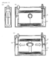
- Figure 2 ((a)-(c)) is cross-sectional view of a lithium ion secondary battery according to the present example, where Figure 2 (a) is a side cross-sectional view, whereas Figure 2 ((a) and (c)) is front cross-sectional view.
- Figure 2 ((a) and (b)) is diagram in the case of normal charge
- Figure 2 (c) is a diagram in the case of over charge.
- This example is an example of using a shape-memory member in the shape of a C-shaped ring as the temperature-sensitive deformation member.
- the lithium-ion secondary battery it is the inside of the electrode assembly where the temperature is most increased in an overcharge condition, and it is preferable to place the temperature-sensitive deformation member inside the battery.
- a temperature-sensitive deformation member 21 is placed in contact with a pair of lead push members 23 inside the electrode assembly. These lead push members 23 are placed to surround and support the shape-memory member. Lead-like members 24, 25 are placed between the lead push members 23 and the battery can 11, which are respectively connected to an external positive electrode terminal 16 and an external negative electrode terminal 15.
- the shape-memory member 21 is shaped by compressive fixation, with compressive strain remaining.
- the increased temperature of the battery body releases the compressive strain of the shape-memory member 21, restores the shape of the shape-memory member 21, and pushes the push rod-like bodies 23 to move the push rod-like bodies 23 for sliding in the horizontal direction illustrated.
- the lead-like members 24, 25 are brought into contact with the battery can 11 to cause short circuit.
- the short circuit that connects the fuse member 22, the lead-like member 24, the battery can 11, the lead-like member 25, and the electrode assembly is closed from the electrode assembly, a large current is allowed to flow by electrical energy accumulated in the electrode assembly, and at the fuse unit 22, the fuse is melted down by an increase in temperature due to the resistance.
- the charging current path is shut off to resolve the overcharge condition.
- Figure 3 are schematic cross-sectional views of a lithium ion secondary battery, as with Figure 2 ((a)-(c)).
- the difference of Example 2 from Example 1 described above is that the lead push members 23 push the lead-like members 24, 25, thereby resulting in short circuit between the lead-like members 24, 25 and the battery can 11 in Example 1.
- a relatively light rod-like member 31 is placed between lead push members 23 and lead-like members 24, 25.
- Example 2 the use of the rod-like member 31 reduce the mass of a member to be moved in the case of falling into an overcharge condition, and as a result, ensures that a switch member can be also driven by the restoring force of a small shape-memory member, thereby making it possible to further ensure the achievement of the operation for overcharge prevention.
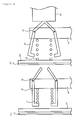
- Example 3 will be described with reference to Figure 4 ((a) and (b)) illustrating a main part of an overcharge prevention mechanism.
- Figure 4 ((a) and (b)) is schematic diagram illustrating an enlarged portion near a switch member.
- Figure 4 (a) is a diagram in the case of normal charge
- Figure 4 (b) is a diagram in the case of abnormal charge.
- a spring 31 is locked and compressed by a supporting member (not illustrated) fixed to a battery can and a spring holder 42.
- the spring holder 42 is a member attached rotatably around a support shaft 43 on the supporting member (not illustrated), and it is preferable to lock the spring 41 with two or more spring holders 42.
Landscapes
- Chemical & Material Sciences (AREA)
- Engineering & Computer Science (AREA)
- General Chemical & Material Sciences (AREA)
- Chemical Kinetics & Catalysis (AREA)
- Electrochemistry (AREA)
- Manufacturing & Machinery (AREA)
- Automation & Control Theory (AREA)
- Materials Engineering (AREA)
- Physics & Mathematics (AREA)
- Condensed Matter Physics & Semiconductors (AREA)
- General Physics & Mathematics (AREA)
- Inorganic Chemistry (AREA)
- Secondary Cells (AREA)
- Connection Of Batteries Or Terminals (AREA)
Abstract
Description
- Embodiments described herein relate generally to a lithium ion secondary battery.
- In recent years, automobiles using secondary batteries as energy sources have been put into practical use, for the reduction of carbon-dioxide emissions, concern over the depletion of fossil fuels such as gasoline. The secondary batteries are required to be high in output power, high in energy density, reduced in size and weight, low in price, or the like, and the improvement in safety and durability is also indispensable for the secondary batteries.
- Lithium ion secondary batteries are known as high energy-density secondary batteries for automobiles. The high energy-density lithium ion secondary battery typically has an electrode assembly obtained by rolling up a positive electrode and a negative electrode stacked with a separator interposed therebetween, impregnated with an organic electrolyte solution, and enclosed in a battery can.
- Because of the use of an organic electrolyte solution in the lithium ion secondary battery, in the case of reaching an overcharge condition, there is a possibility of not only increasing the battery voltage, but also increasing the pressure gas inside the battery, and further increasing the temperature in the battery, thereby leading to situations such as leakage of the electrolyte solution and rupture of the can. The secondary batteries for automobiles are expected to be subjected to the frequent repetition of charge and discharge, and measures against overcharge are thus taken to ensure safety.
- As a measure against overcharge, for example, it is known that a heat generation unit is allowed to generate heat in the case of overcharge, and the container is opened with the heat to release gas during the overcharge.
- [Patent Literature 1] Japanese Patent Application Laid-Open No.
2006-185708 - When the container is opened to release gas as described above, an organic solvent contained in the organic electrolyte solution in the battery will be released to the air to pollute the environment. In addition, because the charging current remains to flow after opening the container, the charging condition will last, and there is also a possibility that the situation will be further worsened.
- The embodiments are aimed at achieving a highly reliable battery which ensure that overcharge conditions can be prevented without any harmful effects on the outside.
- A lithium ion secondary battery according to an embodiment has: an electrode assembly formed by rolling up a positive electrode, a separator, and a negative electrode; an organic electrolyte solution; a positive electrode tab connected to the positive electrode; a negative electrode tab connected to the negative electrode; and an overcharge prevention mechanism, which are incorporated in a battery can sealed with a cap body, and includes: a positive electrode terminal fixed to the cap body, and connected to the positive electrode tab; and a negative electrode terminal fixed to the cap body and connected to the negative electrode tab,
wherein the overcharge prevention mechanism includes: a temperature-sensitive deformation member configured to detect the internal temperature of the electrode assembly to undergo shape change; a switch member configured to be driven by the shape change of the temperature-sensitive deformation member; a fuse member connected in series between the positive electrode terminal and the positive electrode or the negative electrode terminal and the negative electrode; and a short circuit configured to connect the electrode assembly, the fuse member, and the switch member of the lithium ion secondary battery, and when the switch member is driven and turned on by the shape change of the temperature-sensitive deformation member, the short circuit becomes a closed circuit, and the fuse member is melted down by electrical energy accumulated in the electrode assembly to shut off a charging current path. -
- [
Figure 1] Figure 1 is a partially cutaway perspective view illustrating a lithium ion secondary battery example according to an embodiment; - [
Figure 2] Figure 2 is diagram schematically illustrating a lithium ion secondary battery according to Example 1; - [
Figure 3] Figure 3 is diagram schematically illustrating a lithium ion secondary battery according to Example 2; and - [
Figure 4] Figure 4 is diagram schematically illustrating a lithium ion secondary battery according to Example 3. - A lithium ion secondary battery according to an embodiment has: an electrode assembly formed by rolling up a positive electrode, a separator, and a negative electrode; an organic electrolyte solution; a positive electrode tab connected to the positive electrode; a negative electrode tab connected to the negative electrode; and an overcharge prevention mechanism, which are incorporated in a battery can sealed with a cap body, and includes: a positive electrode terminal fixed to the cap body, and connected to the positive electrode tab; and a negative electrode terminal fixed to the cap body and connected to the negative electrode tab.
- Further, the overcharge prevention mechanism includes: a temperature-sensitive deformation member configured to detect the internal temperature of the electrode assembly to undergo shape change; a switch member configured to be driven by the shape change of the temperature-sensitive deformation member; a fuse member connected in series between the positive electrode terminal and the positive electrode or the negative electrode terminal and the negative electrode; and a short circuit configured to connect the electrode assembly, the fuse member, and the switch member of the lithium ion secondary battery.
- In the operation of the overcharge prevention mechanism, in the case of battery overcharge, the battery body undergoes an increase in temperature, as a result, the temperature-sensitive deformation member undergoes a shape change, and a push rod provided in contact with the temperature-sensitive deformation member pushes the switch member to turn on the switch member. As a result, the short circuit becomes a closed circuit, and the fuse member is melted down by electrical energy accumulated in the electrode assembly, to shut off the charging current path.
- The temperature-sensitive deformation member is preferably composed of at least one of a shape-memory alloy, a bimetal, and a wax. The member is further preferably a shape-memory alloy. The shape of the shape-memory alloy is preferably a C-shaped ring.
- The short circuit is preferably partially routed through the battery can. In addition, the fuse member can be composed of a thin part formed on the positive electrode lead or negative electrode lead.
- The switch member includes: a switch unit composed of a lead-like member opposed to the battery can and the battery can; a spring placed near the lead-like member; a spring locking member; and a push rod-like member configured to push out the spring locking member, the spring is compressively fixed by the locking member, in the case of overcharge, the compression of the spring is released in association with the movement of the push rod-like member depending on a deformation of the temperature-sensitive deformation member, and the repulsion force of the spring instantaneously brings the lead-like member and the battery can into contact with each other to close the short circuit, and melt down the fuse member.
- The lithium ion secondary battery according to the present embodiment will be described below in detail with reference to the drawings.
-
Figure 1 illustrates, in the partially cutaway perspective view therein, a structure example of the lithium ion secondary battery according to the present embodiment. - As seen in
Figure 1 , thebattery 10 includes a battery can 11 in the shape of a hollow circular cylinder with a bottom, a hollow cuboid with a bottom, or a hollow cube with a bottom, which includes an opening, and the opening includes a cap body 18 placed for sealing the opening. This cap body 18 is provided withterminals positive electrode 12 and anegative electrode 13 inside via electrode leads 22, 23 such as aluminum foil. Thepositive electrode 12 and thenegative electrode 13 are formed by applying a positive electrode active material and a negative electrode active material respectively on surfaces of thin metal foil. Between the both electrodes, an ion-permeable separator 14 for insulation is stacked on one another, rolled up, shaped so as to be able to be housed in thecan body 11 to make up an electrode assembly, which is housed in the battery can 11 along with an electrolyte solution, not illustrated. - The cap body 18 at the opening of the battery can 11 can be further provided with a
gas release valve 17, so as to be able to release internal gas when the internal pressure in the battery is increased. - In the present embodiment, a means that detects and deals with overcharge conditions can be achieved without using any electronic circuits. Therefore, it becomes possible to achieve a highly reliable overcharge prevention mechanism without any possibility of electronic circuit corrosion or the like in such a condition as under an atmosphere of an organic electrolyte solution.
- Each configuration requirement will be further described below.
- The battery can 11 has the shape of a hollow circular cylinder with a bottom, a hollow cuboid with a bottom, or a hollow cube with a bottom, which includes an opening, which is obtained by shaping a metal such as aluminum. The battery can 11 filled inside with an organic electrolyte solution, can be made of such a material that is not chemically reacted with the organic electrolyte solution, or subjected inside to resin coating for insulation.
- The cap body 18 is formed from an insulating plate material such as polypropylene for insulating the inside from the aluminum plate constituting the exterior unit, and hermetically fixed to the opening of the battery can 11 by means such as a swage. The cap body 18 includes at least two openings formed, which are respectively provided with the
positive electrode terminal 15 and thenegative electrode terminal 16. Furthermore, if necessary, the cap body 18 may be provided with thegas release valve 17 that releases gas when the internal pressure is increased. - The electrode assembly is formed in such a way that the
positive electrode 12, thenegative electrode 13, and theseparator 14 can be stacked on one another, rolled up, and housed in the battery can 11 as described previously. - The positive and
negative electrodes separator 14,tabs tabs negative electrode terminals - The positive electrode is prepared by, for example, applying slurry containing a positive electrode active material to a current collector of aluminum foil or aluminum alloy foil. As the positive electrode active material, which is not to be considered particularly limited, oxides, sulfides, polymer, and the like can be used which can store and release lithium. Preferred active materials include such as lithium-manganese complex oxides, lithium-nickel complex oxides, lithium-cobalt complex oxides, and lithium iron phosphate, which achieves high positive electrode potentials.
- The negative electrode is prepared by applying slurry containing a negative electrode active material to a current collector of aluminum foil or aluminum alloy foil.
- As the negative electrode active material, which is not to be considered particularly limited, metal oxides, metal sulfides, metal nitrides, alloys, and the like can be used which can store and release lithium, and preferably, the negative electrode active material is a material that has an electric potential of 0.4 V or higher for storing or releasing lithium ions with respect to the electric potential of metal lithium. This negative electrode active material which has an electric potential for storing or releasing lithium ions suppresses the alloying reaction between aluminum or an aluminum alloy and lithium, thereby allowing the use of aluminum or an aluminum alloy for the negative current collector and constituent members related to the negative electrode. Examples thereof include, for example, titanium oxides, lithium-titanium oxides, tungsten oxides, amorphous tin oxides, tin-silicon oxides, and silicon oxides, and above all, lithium-titanium complex oxides are preferred.
- Microporous membranes, woven fabrics, non-woven fabrics, laminated products of the same material or different materials thereof, and the like can be used as the separator. Examples of the material forming the separator can include such as polyethylene, polypropylene, ethylene-propylene copolymers, and ethylene-butene copolymers.
- For the electrolyte solution, a non-aqueous electrolyte solution is used which is prepared by dissolving an electrolyte (for example, a lithium salt) in a non-aqueous solvent. Examples of the non-aqueous solvent can include such as, for example, ethylene carbonate (EC), propylene carbonate (PC), butylene carbonate (BC), dimethyl carbonate (DMC), diethyl carbonate (DEC), ethylmethyl carbonate (EMC), γ-butyrolactone (γ-BL), sulfolane, acetonitrile, 1,2-dimethoxyethane, 1,3-dimethoxypropane, dimethyl ether, tetrahydrofurane (THF), 2-methyltetrahydrofuran. The non-aqueous solvents may be used independently, or two or more thereof may be mixed for use. Examples of the electrolyte can include lithium salts such as, for example, lithium perchlorate (LiClO4), lithium hexafluorophosphate(LiPF6), lithium tetrafluoroborate (LiBF4), lithium hexafluoroarsenate (LiAsF6), and lithium trifluoromethanesulfonate (LiCF3SO3). The electrolytes may be used independently, or two or more thereof may be mixed for use. The amount of the electrolyte dissolved in the non-aqueous solvent is desirably 0.2 mol/L to 3 mol/L.
- The materials mentioned for the positive electrode, negative electrode, separator, or organic electrolyte solution are absolutely by way of example only, and the present embodiment is not to be considered limited to these materials.
- The overcharge prevention mechanism according to the present embodiment includes: a temperature-sensitive deformation member configured to detect the internal temperature of the electrode assembly to undergo shape change; a switch member configured to be driven by the shape change of the temperature-sensitive deformation member; a fuse member connected in series between the positive electrode terminal and the positive electrode or the negative electrode terminal and the negative electrode; and a short circuit configured to connect the electrode assembly, the fuse member, and the switch member of the lithium ion secondary battery.
- Further, in the case of lithium ion secondary battery overcharge, the battery body undergoes an increase in temperature, as a result, the temperature-sensitive deformation member undergoes a shape change, and a push rod provided in contact with the temperature-sensitive deformation member pushes the switch member to turn on the switch member. As a result, the short circuit becomes a closed circuit, and the fuse member is melted down by energy accumulated in the electrode assembly, to shut off the charging current path.
- The overcharge prevention mechanism will be described below with reference to examples.
- The overcharge prevention mechanism according to the present example will be described below with reference to
Figure 2 ((a)-(c)). It is to be noted that the description of what is illustrated inFigure 1 will be omitted. -
Figure 2 ((a)-(c)) is cross-sectional view of a lithium ion secondary battery according to the present example, whereFigure 2 (a) is a side cross-sectional view, whereasFigure 2 ((a) and (c)) is front cross-sectional view. In addition,Figure 2 ((a) and (b)) is diagram in the case of normal charge, whereFigure 2 (c) is a diagram in the case of over charge. - This example is an example of using a shape-memory member in the shape of a C-shaped ring as the temperature-sensitive deformation member. In the case of the lithium-ion secondary battery, it is the inside of the electrode assembly where the temperature is most increased in an overcharge condition, and it is preferable to place the temperature-sensitive deformation member inside the battery.
- As seen in
Figure 2 (b) , a temperature-sensitive deformation member 21 is placed in contact with a pair oflead push members 23 inside the electrode assembly. Theselead push members 23 are placed to surround and support the shape-memory member. Lead-like members lead push members 23 and the battery can 11, which are respectively connected to an externalpositive electrode terminal 16 and an externalnegative electrode terminal 15. The shape-memory member 21 is shaped by compressive fixation, with compressive strain remaining. - In the case of reaching an overcharge condition during the battery charging, the increased temperature of the battery body releases the compressive strain of the shape-
memory member 21, restores the shape of the shape-memory member 21, and pushes the push rod-like bodies 23 to move the push rod-like bodies 23 for sliding in the horizontal direction illustrated. As a result, the lead-like members fuse member 22, the lead-like member 24, the battery can 11, the lead-like member 25, and the electrode assembly is closed from the electrode assembly, a large current is allowed to flow by electrical energy accumulated in the electrode assembly, and at thefuse unit 22, the fuse is melted down by an increase in temperature due to the resistance. As a result, the charging current path is shut off to resolve the overcharge condition. - The present example will be described with reference to
Figure 3 ((a)-(c)) which are schematic cross-sectional views of a lithium ion secondary battery according to Example 2. -
Figure 3 ((a)-(c)) are schematic cross-sectional views of a lithium ion secondary battery, as withFigure 2 ((a)-(c)). The difference of Example 2 from Example 1 described above is that thelead push members 23 push the lead-like members like members like member 31 is placed betweenlead push members 23 and lead-like members - As just described, in Example 2, the use of the rod-
like member 31 reduce the mass of a member to be moved in the case of falling into an overcharge condition, and as a result, ensures that a switch member can be also driven by the restoring force of a small shape-memory member, thereby making it possible to further ensure the achievement of the operation for overcharge prevention. - Example 3 will be described with reference to
Figure 4 ((a) and (b)) illustrating a main part of an overcharge prevention mechanism. -
Figure 4 ((a) and (b)) is schematic diagram illustrating an enlarged portion near a switch member.Figure 4 (a) is a diagram in the case of normal charge, whereFigure 4 (b) is a diagram in the case of abnormal charge. - In
Figure 4 (a) , aspring 31 is locked and compressed by a supporting member (not illustrated) fixed to a battery can and aspring holder 42. Thespring holder 42 is a member attached rotatably around asupport shaft 43 on the supporting member (not illustrated), and it is preferable to lock thespring 41 with two ormore spring holders 42. - In the case of abnormal charge, when the temperature of the electrode assembly in the battery body is increased to slide
lead push members 23 in the horizontal direction and push out the lead push members, tips of thespring holder 42 on the battery can side move in opening directions to release the lock on thespring 41 as seen inFigure 4 (b) . As a result, thespring 31 instantaneously pushes a lead-like member 24 to cause short circuit between the lead-like member 24 and the battery can 11. In this way, the short circuit is closed to melt down a fuse member, not illustrated inFigure 4 (a) or Figure 4 (b) , and interrupt the charging current. - While the several embodiments and examples of the present invention have been described above, these embodiments are presented by way of example, and not intended to limit the scope of the invention. The embodiments can be implemented in various other ways, and various omissions, substitutions, and modifications can be made without departing from the spirit of the invention. The embodiments and variations thereof are considered to fall within the scope and spirit of the invention, as well as within the invention as set forth in the claims and equivalents thereof.
-
- 10
- Lithium ion secondary battery
- 11
- Battery can
- 12
- Positive electrode
- 13
- Negative electrode
- 14
- Separator
- 15
- Positive electrode terminal
- 16
- Negative electrode terminal
- 17
- Gas release valve
- 18
- Cap body
- 21
- Shape-memory member
- 22
- Fuse member
- 23
- Lead push member
- 24, 25
- Lead like member
- 31
- Rod-like member
- 26
- Switch member
- 41
- Spring
- 42
- Spring Holder
- 43
- Support Shaft
Claims (6)
- A lithium ion secondary battery comprising: an electrode assembly formed by rolling up a positive electrode, a separator, and a negative electrode; an organic electrolyte solution; a positive electrode tab connected to the positive electrode; a negative electrode tab connected to the negative electrode; and an overcharge prevention mechanism, which are incorporated in a battery can sealed with a cap body, and comprising: a positive electrode terminal fixed to the cap body, and connected to the positive electrode tab; and a negative electrode terminal fixed to the cap body and connected to the negative electrode tab,
wherein the overcharge prevention mechanism comprises: a temperature-sensitive deformation member configured to detect the internal temperature of the electrode assembly to undergo shape change by; a switch member configured to be driven by the shape change of the temperature-sensitive deformation member; a fuse member connected in series between the positive electrode terminal and the positive electrode or the negative electrode terminal and the negative electrode; and a short circuit configured to connect the electrode assembly, the fuse member, and the switch member of the lithium ion secondary battery, and when the switch member is driven and turned on by the shape change of the temperature-sensitive deformation member, the short circuit becomes a closed circuit, and the fuse member is melted down by electrical energy accumulated in the electrode assembly to shut off a charging current path. - The lithium ion secondary battery according to claim 1, wherein the temperature-sensitive deformation member comprises at least one of a shape-memory alloy, a bimetal, and a wax.
- The lithium ion secondary battery according to claim 1 or 2, wherein the short circuit comprises two switch members in contact with the battery can, and when the short circuit is a closed circuit, a short-circuit current passes through the battery can.
- The lithium ion secondary battery according to claim 1, wherein the fuse member comprises a thin part formed on either a positive electrode lead or a negative electrode lead extracted from the electrode assembly.
- The lithium ion secondary battery according to any of claims 1 to 4, wherein the switch member comprises: a switch unit including a lead-like member opposed to the battery can and the battery can; a spring placed near the lead-like member; a spring locking member; and a push rod-like member configured to push out the spring locking member, the spring is compressively fixed by the locking member, in the case of overcharge, the compression of the spring is released in association with a movement of the push rod-like member depending on a deformation of the temperature-sensitive deformation member, and a repulsion force of the spring instantaneously brings the lead-like member and the battery can into contact with each other to close the short circuit, and melt down the fuse member.
- The lithium ion secondary battery according to any of claims 1 to 5, wherein the temperature-sensitive deformation member has a substantially C-ring shape formed from a shape-memory alloy.
Applications Claiming Priority (2)
| Application Number | Priority Date | Filing Date | Title |
|---|---|---|---|
| JP2012059023 | 2012-03-15 | ||
| PCT/JP2013/057449 WO2013137450A1 (en) | 2012-03-15 | 2013-03-15 | Lithium-ion rechargeable battery |
Publications (3)
| Publication Number | Publication Date |
|---|---|
| EP2827407A1 true EP2827407A1 (en) | 2015-01-21 |
| EP2827407A4 EP2827407A4 (en) | 2015-11-18 |
| EP2827407B1 EP2827407B1 (en) | 2017-06-07 |
Family
ID=49161345
Family Applications (1)
| Application Number | Title | Priority Date | Filing Date |
|---|---|---|---|
| EP13760303.1A Not-in-force EP2827407B1 (en) | 2012-03-15 | 2013-03-15 | Lithium-ion rechargeable battery |
Country Status (5)
| Country | Link |
|---|---|
| US (1) | US9437904B2 (en) |
| EP (1) | EP2827407B1 (en) |
| JP (1) | JP5727090B2 (en) |
| CN (1) | CN103703590B (en) |
| WO (1) | WO2013137450A1 (en) |
Families Citing this family (16)
| Publication number | Priority date | Publication date | Assignee | Title |
|---|---|---|---|---|
| KR101696010B1 (en) | 2013-06-19 | 2017-01-12 | 삼성에스디아이 주식회사 | Rechargeable battery |
| JP6120000B2 (en) * | 2013-12-26 | 2017-04-26 | 株式会社豊田自動織機 | Power storage device |
| KR102248595B1 (en) | 2014-04-15 | 2021-05-06 | 삼성에스디아이 주식회사 | Secondary Battery |
| US9985271B2 (en) | 2014-07-31 | 2018-05-29 | Johnson Controls Technology Company | Overcharge protection device for a battery module |
| US9741997B2 (en) | 2014-11-05 | 2017-08-22 | Samsung Sdi Co., Ltd. | Rechargeable battery |
| TWI621296B (en) * | 2014-12-19 | 2018-04-11 | Huang hong wen | Protective secondary battery pack |
| EP3142172A1 (en) * | 2015-09-10 | 2017-03-15 | Lithium Energy and Power GmbH & Co. KG | Battery system with an overcharge and/or deep discharge protection |
| KR102325844B1 (en) | 2016-10-21 | 2021-11-11 | 삼성에스디아이 주식회사 | Rechargeable battery |
| KR102201342B1 (en) | 2017-07-06 | 2021-01-08 | 주식회사 엘지화학 | Battery module, battery pack including the same, and vehicle including the same |
| WO2019026168A1 (en) * | 2017-08-01 | 2019-02-07 | 日産自動車株式会社 | Cell unit |
| CN109962183B (en) * | 2017-12-25 | 2021-09-21 | 比亚迪股份有限公司 | Battery cover plate assembly, single battery, battery module, power battery pack and electric automobile |
| KR102703641B1 (en) * | 2018-12-17 | 2024-09-06 | 주식회사 엘지에너지솔루션 | Current short device, secondary battery including the same and battery module |
| KR102847786B1 (en) * | 2019-10-24 | 2025-08-19 | 주식회사 엘지에너지솔루션 | Secondary battery and battery pack including the same |
| CN111430655A (en) * | 2020-04-22 | 2020-07-17 | 福建飞毛腿动力科技有限公司 | Fusing protection structure with temperature shell fragment |
| US20220109204A1 (en) * | 2020-10-02 | 2022-04-07 | American Lithium Energy Corporation | Impact resistant battery cell |
| CN112968256A (en) * | 2021-02-03 | 2021-06-15 | 东莞新能安科技有限公司 | Electrochemical device and electronic device |
Family Cites Families (17)
| Publication number | Priority date | Publication date | Assignee | Title |
|---|---|---|---|---|
| US4188460A (en) * | 1978-05-01 | 1980-02-12 | P. R. Mallory & Co., Inc. | Internal battery fuse |
| US4975341A (en) * | 1990-04-03 | 1990-12-04 | Eveready Battery Company, Inc. | Electrochemical cell with circuit disconnect device |
| JPH10326610A (en) * | 1997-05-27 | 1998-12-08 | Hitachi Ltd | Non-aqueous electrolyte secondary battery |
| JP2000294226A (en) * | 1999-04-06 | 2000-10-20 | Toyota Central Res & Dev Lab Inc | Sealed secondary battery |
| JP2002095157A (en) * | 2000-07-10 | 2002-03-29 | Matsushita Electric Ind Co Ltd | Overcharge prevention circuit |
| JP5002894B2 (en) | 2004-12-27 | 2012-08-15 | 日産自動車株式会社 | Secondary battery |
| US7952330B2 (en) * | 2005-04-20 | 2011-05-31 | Panasonic Corporation | Secondary battery protection circuit, battery pack and thermosensitive protection switch device |
| JP4884694B2 (en) * | 2005-04-20 | 2012-02-29 | パナソニック株式会社 | Secondary battery protection circuit and battery pack |
| KR100786941B1 (en) | 2005-05-10 | 2007-12-17 | 주식회사 엘지화학 | Protection circuit for secondary battery and secondary battery comprising the same |
| JP4952878B2 (en) * | 2005-09-16 | 2012-06-13 | ソニー株式会社 | Primary battery |
| US7763375B2 (en) * | 2006-05-24 | 2010-07-27 | Eveready Battery Company, Inc. | Current interrupt device for batteries |
| JP2008311106A (en) * | 2007-06-15 | 2008-12-25 | Sanyo Electric Co Ltd | Pack battery |
| CN201226364Y (en) * | 2007-12-14 | 2009-04-22 | 万向集团公司 | Dynamic cell module |
| KR101041153B1 (en) * | 2009-03-04 | 2011-06-13 | 에스비리모티브 주식회사 | Secondary Battery and Its Module |
| US8236439B2 (en) * | 2009-08-14 | 2012-08-07 | Sb Limotive Co., Ltd. | Rechargeable battery |
| US8632911B2 (en) * | 2010-01-15 | 2014-01-21 | Samsung Sdi Co., Ltd. | Rechargeable battery |
| KR101243475B1 (en) * | 2011-03-30 | 2013-03-13 | 로베르트 보쉬 게엠베하 | Secondary battery including short-member |
-
2013
- 2013-03-15 CN CN201380002398.6A patent/CN103703590B/en not_active Expired - Fee Related
- 2013-03-15 JP JP2014505032A patent/JP5727090B2/en not_active Expired - Fee Related
- 2013-03-15 WO PCT/JP2013/057449 patent/WO2013137450A1/en not_active Ceased
- 2013-03-15 EP EP13760303.1A patent/EP2827407B1/en not_active Not-in-force
-
2014
- 2014-02-21 US US14/186,451 patent/US9437904B2/en not_active Expired - Fee Related
Also Published As
| Publication number | Publication date |
|---|---|
| EP2827407B1 (en) | 2017-06-07 |
| CN103703590A (en) | 2014-04-02 |
| US20140170449A1 (en) | 2014-06-19 |
| EP2827407A4 (en) | 2015-11-18 |
| WO2013137450A1 (en) | 2013-09-19 |
| CN103703590B (en) | 2016-11-16 |
| US9437904B2 (en) | 2016-09-06 |
| JPWO2013137450A1 (en) | 2015-08-03 |
| JP5727090B2 (en) | 2015-06-03 |
Similar Documents
| Publication | Publication Date | Title |
|---|---|---|
| EP2827407B1 (en) | Lithium-ion rechargeable battery | |
| EP2827408B1 (en) | Lithium-ion rechargeable battery | |
| US10985400B2 (en) | Nonaqueous electrolyte secondary battery and method for manufacturing the same | |
| KR101946732B1 (en) | Nonaqueous electrolyte battery and battery system | |
| US6586131B2 (en) | Apparatus for releasing gases from rechargeable lithium electrochemical cells during the formation stage of manufacturing | |
| JP6058400B2 (en) | Non-aqueous electrolyte secondary battery | |
| US12438196B2 (en) | Electrolytes for lithium batteries | |
| KR101614185B1 (en) | Positive electrode material for improved safety, and lithium secondary battery comprising the same | |
| US9142862B2 (en) | Nonaqueous electrolyte secondary battery | |
| JP6661485B2 (en) | Non-aqueous electrolyte secondary battery | |
| US20140002942A1 (en) | Secondary Lithium Ion Battery With Mixed Nickelate Cathodes | |
| KR20170009065A (en) | Rechargeable secondary battery | |
| JP2011210390A (en) | Battery and battery module | |
| EP2405523B1 (en) | Nonaqueous electrolyte comprising oxyanions and lithium secondary battery using the same | |
| JP2000067847A (en) | Rechargeable batteries and assembled batteries | |
| US12362359B2 (en) | Positive electrode for secondary battery, and secondary battery | |
| KR20130131983A (en) | Secondary battery comprising apparatus for preventing overcharge | |
| JP2002289159A (en) | Non-aqueous electrolyte secondary battery pack | |
| JP6639111B2 (en) | Rechargeable battery | |
| US20190372175A1 (en) | Solid state batteries | |
| JP4538866B2 (en) | Non-aqueous electrolyte electrochemical device | |
| JP2000188132A (en) | Nonaqueous electrode secondary battery | |
| WO2022080050A1 (en) | Secondary battery | |
| JPH1145701A (en) | Sealed non-aqueous electrolyte battery | |
| JPH0831450A (en) | Sealed nonaqueous electrolyte secondary battery |
Legal Events
| Date | Code | Title | Description |
|---|---|---|---|
| PUAI | Public reference made under article 153(3) epc to a published international application that has entered the european phase |
Free format text: ORIGINAL CODE: 0009012 |
|
| 17P | Request for examination filed |
Effective date: 20140224 |
|
| AK | Designated contracting states |
Kind code of ref document: A1 Designated state(s): AL AT BE BG CH CY CZ DE DK EE ES FI FR GB GR HR HU IE IS IT LI LT LU LV MC MK MT NL NO PL PT RO RS SE SI SK SM TR |
|
| AX | Request for extension of the european patent |
Extension state: BA ME |
|
| DAX | Request for extension of the european patent (deleted) | ||
| RA4 | Supplementary search report drawn up and despatched (corrected) |
Effective date: 20151020 |
|
| RIC1 | Information provided on ipc code assigned before grant |
Ipc: H01M 10/0587 20100101ALI20151014BHEP Ipc: H01M 10/0566 20100101ALI20151014BHEP Ipc: H01M 10/48 20060101ALI20151014BHEP Ipc: H02H 7/18 20060101ALI20151014BHEP Ipc: H01M 10/052 20100101ALI20151014BHEP Ipc: H01M 10/637 20140101ALI20151014BHEP Ipc: H02J 7/00 20060101ALN20151014BHEP Ipc: H01M 2/34 20060101AFI20151014BHEP Ipc: H01M 10/04 20060101ALI20151014BHEP |
|
| R17P | Request for examination filed (corrected) |
Effective date: 20140224 |
|
| GRAP | Despatch of communication of intention to grant a patent |
Free format text: ORIGINAL CODE: EPIDOSNIGR1 |
|
| STAA | Information on the status of an ep patent application or granted ep patent |
Free format text: STATUS: GRANT OF PATENT IS INTENDED |
|
| RIC1 | Information provided on ipc code assigned before grant |
Ipc: H01M 10/04 20060101ALI20161124BHEP Ipc: H02J 7/00 20060101ALN20161124BHEP Ipc: H01M 10/052 20100101ALI20161124BHEP Ipc: H01M 10/48 20060101ALI20161124BHEP Ipc: H01M 10/0587 20100101ALI20161124BHEP Ipc: H02H 7/18 20060101ALI20161124BHEP Ipc: H01M 10/637 20140101ALI20161124BHEP Ipc: H01M 2/34 20060101AFI20161124BHEP Ipc: H01M 10/0566 20100101ALI20161124BHEP |
|
| RIC1 | Information provided on ipc code assigned before grant |
Ipc: H01M 10/0566 20100101ALI20161129BHEP Ipc: H01M 10/48 20060101ALI20161129BHEP Ipc: H01M 10/052 20100101ALI20161129BHEP Ipc: H01M 10/04 20060101ALI20161129BHEP Ipc: H02H 7/18 20060101ALI20161129BHEP Ipc: H01M 10/0587 20100101ALI20161129BHEP Ipc: H01M 10/637 20140101ALI20161129BHEP Ipc: H02J 7/00 20060101ALN20161129BHEP Ipc: H01M 2/34 20060101AFI20161129BHEP |
|
| INTG | Intention to grant announced |
Effective date: 20161223 |
|
| GRAS | Grant fee paid |
Free format text: ORIGINAL CODE: EPIDOSNIGR3 |
|
| AK | Designated contracting states |
Kind code of ref document: B1 Designated state(s): AL AT BE BG CH CY CZ DE DK EE ES FI FR GB GR HR HU IE IS IT LI LT LU LV MC MK MT NL NO PL PT RO RS SE SI SK SM TR |
|
| REG | Reference to a national code |
Ref country code: GB Ref legal event code: FG4D |
|
| GRAA | (expected) grant |
Free format text: ORIGINAL CODE: 0009210 |
|
| REG | Reference to a national code |
Ref country code: CH Ref legal event code: EP Ref country code: AT Ref legal event code: REF Ref document number: 899831 Country of ref document: AT Kind code of ref document: T Effective date: 20170615 |
|
| STAA | Information on the status of an ep patent application or granted ep patent |
Free format text: STATUS: THE PATENT HAS BEEN GRANTED |
|
| REG | Reference to a national code |
Ref country code: IE Ref legal event code: FG4D |
|
| REG | Reference to a national code |
Ref country code: DE Ref legal event code: R096 Ref document number: 602013022006 Country of ref document: DE |
|
| REG | Reference to a national code |
Ref country code: NL Ref legal event code: MP Effective date: 20170607 |
|
| REG | Reference to a national code |
Ref country code: LT Ref legal event code: MG4D |
|
| PG25 | Lapsed in a contracting state [announced via postgrant information from national office to epo] |
Ref country code: HR Free format text: LAPSE BECAUSE OF FAILURE TO SUBMIT A TRANSLATION OF THE DESCRIPTION OR TO PAY THE FEE WITHIN THE PRESCRIBED TIME-LIMIT Effective date: 20170607 Ref country code: LT Free format text: LAPSE BECAUSE OF FAILURE TO SUBMIT A TRANSLATION OF THE DESCRIPTION OR TO PAY THE FEE WITHIN THE PRESCRIBED TIME-LIMIT Effective date: 20170607 Ref country code: FI Free format text: LAPSE BECAUSE OF FAILURE TO SUBMIT A TRANSLATION OF THE DESCRIPTION OR TO PAY THE FEE WITHIN THE PRESCRIBED TIME-LIMIT Effective date: 20170607 Ref country code: NO Free format text: LAPSE BECAUSE OF FAILURE TO SUBMIT A TRANSLATION OF THE DESCRIPTION OR TO PAY THE FEE WITHIN THE PRESCRIBED TIME-LIMIT Effective date: 20170907 Ref country code: ES Free format text: LAPSE BECAUSE OF FAILURE TO SUBMIT A TRANSLATION OF THE DESCRIPTION OR TO PAY THE FEE WITHIN THE PRESCRIBED TIME-LIMIT Effective date: 20170607 Ref country code: GR Free format text: LAPSE BECAUSE OF FAILURE TO SUBMIT A TRANSLATION OF THE DESCRIPTION OR TO PAY THE FEE WITHIN THE PRESCRIBED TIME-LIMIT Effective date: 20170908 |
|
| REG | Reference to a national code |
Ref country code: AT Ref legal event code: MK05 Ref document number: 899831 Country of ref document: AT Kind code of ref document: T Effective date: 20170607 |
|
| PG25 | Lapsed in a contracting state [announced via postgrant information from national office to epo] |
Ref country code: NL Free format text: LAPSE BECAUSE OF FAILURE TO SUBMIT A TRANSLATION OF THE DESCRIPTION OR TO PAY THE FEE WITHIN THE PRESCRIBED TIME-LIMIT Effective date: 20170607 Ref country code: RS Free format text: LAPSE BECAUSE OF FAILURE TO SUBMIT A TRANSLATION OF THE DESCRIPTION OR TO PAY THE FEE WITHIN THE PRESCRIBED TIME-LIMIT Effective date: 20170607 Ref country code: LV Free format text: LAPSE BECAUSE OF FAILURE TO SUBMIT A TRANSLATION OF THE DESCRIPTION OR TO PAY THE FEE WITHIN THE PRESCRIBED TIME-LIMIT Effective date: 20170607 Ref country code: BG Free format text: LAPSE BECAUSE OF FAILURE TO SUBMIT A TRANSLATION OF THE DESCRIPTION OR TO PAY THE FEE WITHIN THE PRESCRIBED TIME-LIMIT Effective date: 20170907 Ref country code: SE Free format text: LAPSE BECAUSE OF FAILURE TO SUBMIT A TRANSLATION OF THE DESCRIPTION OR TO PAY THE FEE WITHIN THE PRESCRIBED TIME-LIMIT Effective date: 20170607 |
|
| PG25 | Lapsed in a contracting state [announced via postgrant information from national office to epo] |
Ref country code: EE Free format text: LAPSE BECAUSE OF FAILURE TO SUBMIT A TRANSLATION OF THE DESCRIPTION OR TO PAY THE FEE WITHIN THE PRESCRIBED TIME-LIMIT Effective date: 20170607 Ref country code: CZ Free format text: LAPSE BECAUSE OF FAILURE TO SUBMIT A TRANSLATION OF THE DESCRIPTION OR TO PAY THE FEE WITHIN THE PRESCRIBED TIME-LIMIT Effective date: 20170607 Ref country code: AT Free format text: LAPSE BECAUSE OF FAILURE TO SUBMIT A TRANSLATION OF THE DESCRIPTION OR TO PAY THE FEE WITHIN THE PRESCRIBED TIME-LIMIT Effective date: 20170607 Ref country code: SK Free format text: LAPSE BECAUSE OF FAILURE TO SUBMIT A TRANSLATION OF THE DESCRIPTION OR TO PAY THE FEE WITHIN THE PRESCRIBED TIME-LIMIT Effective date: 20170607 Ref country code: RO Free format text: LAPSE BECAUSE OF FAILURE TO SUBMIT A TRANSLATION OF THE DESCRIPTION OR TO PAY THE FEE WITHIN THE PRESCRIBED TIME-LIMIT Effective date: 20170607 |
|
| REG | Reference to a national code |
Ref country code: FR Ref legal event code: PLFP Year of fee payment: 6 |
|
| PG25 | Lapsed in a contracting state [announced via postgrant information from national office to epo] |
Ref country code: IS Free format text: LAPSE BECAUSE OF FAILURE TO SUBMIT A TRANSLATION OF THE DESCRIPTION OR TO PAY THE FEE WITHIN THE PRESCRIBED TIME-LIMIT Effective date: 20171007 Ref country code: SM Free format text: LAPSE BECAUSE OF FAILURE TO SUBMIT A TRANSLATION OF THE DESCRIPTION OR TO PAY THE FEE WITHIN THE PRESCRIBED TIME-LIMIT Effective date: 20170607 Ref country code: PL Free format text: LAPSE BECAUSE OF FAILURE TO SUBMIT A TRANSLATION OF THE DESCRIPTION OR TO PAY THE FEE WITHIN THE PRESCRIBED TIME-LIMIT Effective date: 20170607 |
|
| REG | Reference to a national code |
Ref country code: DE Ref legal event code: R097 Ref document number: 602013022006 Country of ref document: DE |
|
| PLBE | No opposition filed within time limit |
Free format text: ORIGINAL CODE: 0009261 |
|
| STAA | Information on the status of an ep patent application or granted ep patent |
Free format text: STATUS: NO OPPOSITION FILED WITHIN TIME LIMIT |
|
| PG25 | Lapsed in a contracting state [announced via postgrant information from national office to epo] |
Ref country code: DK Free format text: LAPSE BECAUSE OF FAILURE TO SUBMIT A TRANSLATION OF THE DESCRIPTION OR TO PAY THE FEE WITHIN THE PRESCRIBED TIME-LIMIT Effective date: 20170607 |
|
| 26N | No opposition filed |
Effective date: 20180308 |
|
| PG25 | Lapsed in a contracting state [announced via postgrant information from national office to epo] |
Ref country code: SI Free format text: LAPSE BECAUSE OF FAILURE TO SUBMIT A TRANSLATION OF THE DESCRIPTION OR TO PAY THE FEE WITHIN THE PRESCRIBED TIME-LIMIT Effective date: 20170607 |
|
| REG | Reference to a national code |
Ref country code: CH Ref legal event code: PL |
|
| GBPC | Gb: european patent ceased through non-payment of renewal fee |
Effective date: 20180315 |
|
| PG25 | Lapsed in a contracting state [announced via postgrant information from national office to epo] |
Ref country code: MC Free format text: LAPSE BECAUSE OF FAILURE TO SUBMIT A TRANSLATION OF THE DESCRIPTION OR TO PAY THE FEE WITHIN THE PRESCRIBED TIME-LIMIT Effective date: 20170607 |
|
| REG | Reference to a national code |
Ref country code: BE Ref legal event code: MM Effective date: 20180331 |
|
| REG | Reference to a national code |
Ref country code: IE Ref legal event code: MM4A |
|
| PG25 | Lapsed in a contracting state [announced via postgrant information from national office to epo] |
Ref country code: LU Free format text: LAPSE BECAUSE OF NON-PAYMENT OF DUE FEES Effective date: 20180315 |
|
| PG25 | Lapsed in a contracting state [announced via postgrant information from national office to epo] |
Ref country code: IE Free format text: LAPSE BECAUSE OF NON-PAYMENT OF DUE FEES Effective date: 20180315 |
|
| PG25 | Lapsed in a contracting state [announced via postgrant information from national office to epo] |
Ref country code: BE Free format text: LAPSE BECAUSE OF NON-PAYMENT OF DUE FEES Effective date: 20180331 Ref country code: CH Free format text: LAPSE BECAUSE OF NON-PAYMENT OF DUE FEES Effective date: 20180331 Ref country code: GB Free format text: LAPSE BECAUSE OF NON-PAYMENT OF DUE FEES Effective date: 20180315 Ref country code: LI Free format text: LAPSE BECAUSE OF NON-PAYMENT OF DUE FEES Effective date: 20180331 |
|
| PG25 | Lapsed in a contracting state [announced via postgrant information from national office to epo] |
Ref country code: MT Free format text: LAPSE BECAUSE OF NON-PAYMENT OF DUE FEES Effective date: 20180315 |
|
| PG25 | Lapsed in a contracting state [announced via postgrant information from national office to epo] |
Ref country code: TR Free format text: LAPSE BECAUSE OF FAILURE TO SUBMIT A TRANSLATION OF THE DESCRIPTION OR TO PAY THE FEE WITHIN THE PRESCRIBED TIME-LIMIT Effective date: 20170607 |
|
| PG25 | Lapsed in a contracting state [announced via postgrant information from national office to epo] |
Ref country code: PT Free format text: LAPSE BECAUSE OF FAILURE TO SUBMIT A TRANSLATION OF THE DESCRIPTION OR TO PAY THE FEE WITHIN THE PRESCRIBED TIME-LIMIT Effective date: 20170607 Ref country code: HU Free format text: LAPSE BECAUSE OF FAILURE TO SUBMIT A TRANSLATION OF THE DESCRIPTION OR TO PAY THE FEE WITHIN THE PRESCRIBED TIME-LIMIT; INVALID AB INITIO Effective date: 20130315 |
|
| PG25 | Lapsed in a contracting state [announced via postgrant information from national office to epo] |
Ref country code: CY Free format text: LAPSE BECAUSE OF FAILURE TO SUBMIT A TRANSLATION OF THE DESCRIPTION OR TO PAY THE FEE WITHIN THE PRESCRIBED TIME-LIMIT Effective date: 20170607 Ref country code: MK Free format text: LAPSE BECAUSE OF NON-PAYMENT OF DUE FEES Effective date: 20170607 |
|
| PG25 | Lapsed in a contracting state [announced via postgrant information from national office to epo] |
Ref country code: AL Free format text: LAPSE BECAUSE OF FAILURE TO SUBMIT A TRANSLATION OF THE DESCRIPTION OR TO PAY THE FEE WITHIN THE PRESCRIBED TIME-LIMIT Effective date: 20170607 |
|
| REG | Reference to a national code |
Ref country code: DE Ref legal event code: R079 Ref document number: 602013022006 Country of ref document: DE Free format text: PREVIOUS MAIN CLASS: H01M0002340000 Ipc: H01M0050572000 |
|
| PGFP | Annual fee paid to national office [announced via postgrant information from national office to epo] |
Ref country code: FR Payment date: 20231229 Year of fee payment: 12 |
|
| PGFP | Annual fee paid to national office [announced via postgrant information from national office to epo] |
Ref country code: DE Payment date: 20231229 Year of fee payment: 12 |
|
| PGFP | Annual fee paid to national office [announced via postgrant information from national office to epo] |
Ref country code: IT Payment date: 20240212 Year of fee payment: 12 |
|
| REG | Reference to a national code |
Ref country code: DE Ref legal event code: R119 Ref document number: 602013022006 Country of ref document: DE |
|
| PG25 | Lapsed in a contracting state [announced via postgrant information from national office to epo] |
Ref country code: DE Free format text: LAPSE BECAUSE OF NON-PAYMENT OF DUE FEES Effective date: 20251001 |
|
| PG25 | Lapsed in a contracting state [announced via postgrant information from national office to epo] |
Ref country code: FR Free format text: LAPSE BECAUSE OF NON-PAYMENT OF DUE FEES Effective date: 20250331 Ref country code: IT Free format text: LAPSE BECAUSE OF NON-PAYMENT OF DUE FEES Effective date: 20250315 |