EP2827280A1 - System and method for polling NFC-A devices alongside RF barcodes - Google Patents
System and method for polling NFC-A devices alongside RF barcodes Download PDFInfo
- Publication number
- EP2827280A1 EP2827280A1 EP13176840.0A EP13176840A EP2827280A1 EP 2827280 A1 EP2827280 A1 EP 2827280A1 EP 13176840 A EP13176840 A EP 13176840A EP 2827280 A1 EP2827280 A1 EP 2827280A1
- Authority
- EP
- European Patent Office
- Prior art keywords
- nfc
- barcode
- uid
- devices
- transmissions
- Prior art date
- Legal status (The legal status is an assumption and is not a legal conclusion. Google has not performed a legal analysis and makes no representation as to the accuracy of the status listed.)
- Granted
Links
Images


Classifications
-
- G—PHYSICS
- G06—COMPUTING OR CALCULATING; COUNTING
- G06K—GRAPHICAL DATA READING; PRESENTATION OF DATA; RECORD CARRIERS; HANDLING RECORD CARRIERS
- G06K7/00—Methods or arrangements for sensing record carriers, e.g. for reading patterns
- G06K7/10—Methods or arrangements for sensing record carriers, e.g. for reading patterns by electromagnetic radiation, e.g. optical sensing; by corpuscular radiation
- G06K7/10009—Methods or arrangements for sensing record carriers, e.g. for reading patterns by electromagnetic radiation, e.g. optical sensing; by corpuscular radiation sensing by radiation using wavelengths larger than 0.1 mm, e.g. radio-waves or microwaves
- G06K7/10019—Methods or arrangements for sensing record carriers, e.g. for reading patterns by electromagnetic radiation, e.g. optical sensing; by corpuscular radiation sensing by radiation using wavelengths larger than 0.1 mm, e.g. radio-waves or microwaves resolving collision on the communication channels between simultaneously or concurrently interrogated record carriers.
- G06K7/10029—Methods or arrangements for sensing record carriers, e.g. for reading patterns by electromagnetic radiation, e.g. optical sensing; by corpuscular radiation sensing by radiation using wavelengths larger than 0.1 mm, e.g. radio-waves or microwaves resolving collision on the communication channels between simultaneously or concurrently interrogated record carriers. the collision being resolved in the time domain, e.g. using binary tree search or RFID responses allocated to a random time slot
- G06K7/10039—Methods or arrangements for sensing record carriers, e.g. for reading patterns by electromagnetic radiation, e.g. optical sensing; by corpuscular radiation sensing by radiation using wavelengths larger than 0.1 mm, e.g. radio-waves or microwaves resolving collision on the communication channels between simultaneously or concurrently interrogated record carriers. the collision being resolved in the time domain, e.g. using binary tree search or RFID responses allocated to a random time slot interrogator driven, i.e. synchronous
-
- G—PHYSICS
- G06—COMPUTING OR CALCULATING; COUNTING
- G06K—GRAPHICAL DATA READING; PRESENTATION OF DATA; RECORD CARRIERS; HANDLING RECORD CARRIERS
- G06K7/00—Methods or arrangements for sensing record carriers, e.g. for reading patterns
- G06K7/10—Methods or arrangements for sensing record carriers, e.g. for reading patterns by electromagnetic radiation, e.g. optical sensing; by corpuscular radiation
- G06K7/10009—Methods or arrangements for sensing record carriers, e.g. for reading patterns by electromagnetic radiation, e.g. optical sensing; by corpuscular radiation sensing by radiation using wavelengths larger than 0.1 mm, e.g. radio-waves or microwaves
- G06K7/10118—Methods or arrangements for sensing record carriers, e.g. for reading patterns by electromagnetic radiation, e.g. optical sensing; by corpuscular radiation sensing by radiation using wavelengths larger than 0.1 mm, e.g. radio-waves or microwaves the sensing being preceded by at least one preliminary step
- G06K7/10128—Methods or arrangements for sensing record carriers, e.g. for reading patterns by electromagnetic radiation, e.g. optical sensing; by corpuscular radiation sensing by radiation using wavelengths larger than 0.1 mm, e.g. radio-waves or microwaves the sensing being preceded by at least one preliminary step the step consisting of detection of the presence of one or more record carriers in the vicinity of the interrogation device
-
- G—PHYSICS
- G06—COMPUTING OR CALCULATING; COUNTING
- G06K—GRAPHICAL DATA READING; PRESENTATION OF DATA; RECORD CARRIERS; HANDLING RECORD CARRIERS
- G06K7/00—Methods or arrangements for sensing record carriers, e.g. for reading patterns
- G06K7/10—Methods or arrangements for sensing record carriers, e.g. for reading patterns by electromagnetic radiation, e.g. optical sensing; by corpuscular radiation
- G06K7/10009—Methods or arrangements for sensing record carriers, e.g. for reading patterns by electromagnetic radiation, e.g. optical sensing; by corpuscular radiation sensing by radiation using wavelengths larger than 0.1 mm, e.g. radio-waves or microwaves
- G06K7/10118—Methods or arrangements for sensing record carriers, e.g. for reading patterns by electromagnetic radiation, e.g. optical sensing; by corpuscular radiation sensing by radiation using wavelengths larger than 0.1 mm, e.g. radio-waves or microwaves the sensing being preceded by at least one preliminary step
- G06K7/10138—Methods or arrangements for sensing record carriers, e.g. for reading patterns by electromagnetic radiation, e.g. optical sensing; by corpuscular radiation sensing by radiation using wavelengths larger than 0.1 mm, e.g. radio-waves or microwaves the sensing being preceded by at least one preliminary step the step consisting of determining the type of record carrier, e.g. to determine if the record carrier is an RFID tag of the long or short range type, or to determine the preferred communication protocol of the RFID tag
-
- G—PHYSICS
- G06—COMPUTING OR CALCULATING; COUNTING
- G06K—GRAPHICAL DATA READING; PRESENTATION OF DATA; RECORD CARRIERS; HANDLING RECORD CARRIERS
- G06K7/00—Methods or arrangements for sensing record carriers, e.g. for reading patterns
- G06K7/10—Methods or arrangements for sensing record carriers, e.g. for reading patterns by electromagnetic radiation, e.g. optical sensing; by corpuscular radiation
- G06K7/10009—Methods or arrangements for sensing record carriers, e.g. for reading patterns by electromagnetic radiation, e.g. optical sensing; by corpuscular radiation sensing by radiation using wavelengths larger than 0.1 mm, e.g. radio-waves or microwaves
- G06K7/10297—Methods or arrangements for sensing record carriers, e.g. for reading patterns by electromagnetic radiation, e.g. optical sensing; by corpuscular radiation sensing by radiation using wavelengths larger than 0.1 mm, e.g. radio-waves or microwaves arrangements for handling protocols designed for non-contact record carriers such as RFIDs NFCs, e.g. ISO/IEC 14443 and 18092
-
- H—ELECTRICITY
- H04—ELECTRIC COMMUNICATION TECHNIQUE
- H04B—TRANSMISSION
- H04B5/00—Near-field transmission systems, e.g. inductive or capacitive transmission systems
- H04B5/20—Near-field transmission systems, e.g. inductive or capacitive transmission systems characterised by the transmission technique; characterised by the transmission medium
-
- H—ELECTRICITY
- H04—ELECTRIC COMMUNICATION TECHNIQUE
- H04B—TRANSMISSION
- H04B5/00—Near-field transmission systems, e.g. inductive or capacitive transmission systems
- H04B5/70—Near-field transmission systems, e.g. inductive or capacitive transmission systems specially adapted for specific purposes
- H04B5/77—Near-field transmission systems, e.g. inductive or capacitive transmission systems specially adapted for specific purposes for interrogation
-
- H—ELECTRICITY
- H04—ELECTRIC COMMUNICATION TECHNIQUE
- H04W—WIRELESS COMMUNICATION NETWORKS
- H04W74/00—Wireless channel access
- H04W74/08—Non-scheduled access, e.g. ALOHA
- H04W74/0833—Random access procedures, e.g. with 4-step access
- H04W74/0841—Random access procedures, e.g. with 4-step access with collision treatment
- H04W74/085—Random access procedures, e.g. with 4-step access with collision treatment collision avoidance
-
- H—ELECTRICITY
- H04—ELECTRIC COMMUNICATION TECHNIQUE
- H04W—WIRELESS COMMUNICATION NETWORKS
- H04W76/00—Connection management
- H04W76/10—Connection setup
- H04W76/14—Direct-mode setup
-
- G—PHYSICS
- G06—COMPUTING OR CALCULATING; COUNTING
- G06K—GRAPHICAL DATA READING; PRESENTATION OF DATA; RECORD CARRIERS; HANDLING RECORD CARRIERS
- G06K7/00—Methods or arrangements for sensing record carriers, e.g. for reading patterns
- G06K7/10—Methods or arrangements for sensing record carriers, e.g. for reading patterns by electromagnetic radiation, e.g. optical sensing; by corpuscular radiation
- G06K7/10009—Methods or arrangements for sensing record carriers, e.g. for reading patterns by electromagnetic radiation, e.g. optical sensing; by corpuscular radiation sensing by radiation using wavelengths larger than 0.1 mm, e.g. radio-waves or microwaves
- G06K7/10237—Methods or arrangements for sensing record carriers, e.g. for reading patterns by electromagnetic radiation, e.g. optical sensing; by corpuscular radiation sensing by radiation using wavelengths larger than 0.1 mm, e.g. radio-waves or microwaves the reader and the record carrier being capable of selectively switching between reader and record carrier appearance, e.g. in near field communication [NFC] devices where the NFC device may function as an RFID reader or as an RFID tag
Definitions
- This invention relates to Near-Field Communication (NFC) and in particular, but without limitation, to the coexistence of different types of NFC device, such as RF barcode-type devices and another NFC-enabled device.
- NFC Near-Field Communication
- NFC Near-field communication
- RFID radio-frequency identification
- NFC devices communicate via magnetic field induction whereby the loop antenna of the reader device and the loop antenna of the NFC device are located within each other's near field, effectively forming an air-core transformer.
- the loop antenna of the reader device and the loop antenna of the NFC device are located within each other's near field, effectively forming an air-core transformer.
- NFC NFC
- passive communication mode whereby the initiating device provides a carrier field and the target device answers by modulating the carrier field
- active communication mode where both the initiating and target devices communicate by alternately generating their own fields.
- the target device can be a smartcard or a tag, but also more advanced devices, such as mobile phones can have NFC functionality whereby they "emulate” the behavior of an NFC tag. For this reason, when the target device operates in passive communication mode, this is usually called a “tag emulation mode” and the target device can be called a “tag emulator” or "transponder”.
- Such devices can communicate with one another according to operations and protocols defined by the ISO 14443 standard.
- a problem can arise, however, where more than one NFC reader and/or target are in range of one another, because this can lead to data collision and unnecessary bandwidth being used.
- NFC tag which is an RF barcode-type device developed and marketed by the company Kovio TM , (commonly referred to as a "Kovio tag"), comprises a printed integrated circuit (PIC) comprising an antenna, a master circuit, a transponder and a 128-bit ROM.
- PIC printed integrated circuit
- the ROM is loaded with a unique identification code (UID), and the device operates in a passive, read-only mode.
- UID unique identification code
- the RF barcode when the RF barcode enters the RF field of a reader device, it is powered-up and by an induction current in its antenna, and then proceeds to broadcast its 128-bit code (its UID) at intervals.
- the RF barcode operates in a Tags-Talk-First (TTF) mode, it does not accept any commands from a reader but rather, as soon as it receives enough power from the reader's field to operate, it repeatedly transmits its UID at a specific interval, as long as it is powered.
- TTF Tags-Talk-First
- an RF barcode is configured to begin broadcasting its UID within 1ms of entering the RF field (or the RF field being switched on). It takes approximately 1.21ms to broadcast the 128-bit UID, assuming a bit rate of 106 kbps, and this process is repeated every 3.6ms (the "sleep duration") as long as the RF field is present, as depicted in Figures 1 and 2 of the drawings.
- Figure 1 which shows the RF field 10 and the RF barcode response 12 as a function of time on the horizontal axis, it can be seen that the RF field is initially OFF, but after time t 1 , it is switched on.
- the RF barcode is powered-up and activated by the RF field, and within 1ms of t 1 , begins broadcasting its UID 14.
- the UID 14 is made up of a number of pulses representative of the UID.
- Each bit 16 takes 9.44 ⁇ s to transmit, so a 128-bit UID takes 1.21 ms to transmit, assuming a bit rate of 106 kbps.
- the sleep interval 18, i.e. the wait time between successive UID transmissions 14, is 3.6ms.
- NFC-A tags (or other listen mode devices) work in a Request-Response mode, and therefore wait for an NFC-A Poll Request from an NFC reader device before transmitting the NFC-A Poll Response.
- NFC Forum "Type-1 Tag” (T1T), “Type-2 Tag” (T2T) and “Type-4A Tag” (T4AT) are all based on NFC-A technology.
- NFC-A tag and “NFC-A listen mode devices” are essentially the same.
- NFC-DEP based peer-to-peer (P2P) target devices may also be based on NFC-A technology.
- the RF barcode will continue to broadcast its UID. Moreover, because the RF barcode cannot accept a power-down command from the reader device, to halt, or pause, the RF barcode's UID transmission, other NFC traffic, for example, between the reader and other NFC-A devices is adversely affected.
- the NFC reader will switch OFF the RF field upon detection of only RF barcode devices, resulting in a bad user experience because the NFC reader won't detect any NFC-A tags even though NFC-A tags may be present in the RF field.
- the sequence commences by switching ON 20 the RF field, whereupon the ISO 14443-3 polling loop protocol is initialized 22. Within 1ms, 24, polling begins, which starts a "seek" procedure 26. During the seek procedure 26, a guard time 28 of 5ms 28 is waited-out. If an RF barcode is present in the RF field, i.e. if the NFC reader receives the 1 st bit 30 before the expiry of the 5ms guard time 28, then the RF barcode is deemed “detected" 32 and the remainder of the UID is obtained 34.
- the NFC reader will proceed to poll for NFC-A tags 36 only if it doesn't detect an RF barcode within 5ms 28 of switching ON the RF field.
- a method of connecting an NFC reader to a plurality of NFC devices comprising at least one NFC-A device and at least one RF barcode
- the method comprising the steps of: detecting and logging the active and sleep intervals of the RF barcode when an RF field is switched on; and synchronizing the transmission and reception of data to, and from, the or each NFC-A device such that transmission and reception of data to, and from, the or each NFC-A device occurs only when the or each RF barcode is in a sleep interval.
- the RF barcode may be a "Kovio" tag.
- the step of detecting and logging the active and sleep intervals of the RF barcode occurs by switching on an RF field which is capable of powering-up the RF barcode and by listening for a response from the RF barcode.
- the transmission of the RF barcode's UID is suitably timed.
- a timer or clock is used to time the start and end of the UID transmissions.
- the start and end times of the UID transmissions are suitably logged, and the log so produced is suitably stored in a memory device. From the log, the duration and period of the RF barcode's UID transmissions is suitably determinable.
- the detection of RF barcodes is suitably performed prior to the detection of other NFC-A devices.
- a guard time is suitably employed, say of 5ms duration, during which the NFC reader is configured to search only for RF barcodes, and after which guard time, the NFC reader is configured to search for other NFC-A devices. If no RF barcodes are detected within the guard time, the NFC reader may be adapted to operate in a conventional NFC mode of operation, that is to say, according to the NFC-A standard.
- the NFC reader is suitably adapted to operate in a synchronous mode according to the invention, that is to say, whereby the exchange of data with NFC-A devices is synchronized to occur only within the sleep intervals of the RF barcode, that is to say, in the intervals between successive UID transmissions of the RF barcode.
- a second aspect of the invention provides an apparatus for connecting an NFC reader to a plurality of NFC devices, the plurality of NFC devices comprising at least one NFC-A device and at least one RF barcode, the apparatus comprising: an RF transceiver, a clock and a processor, the processor comprising: means for detecting the RF barcode when the RF transceiver is active; and means for monitoring the RF barcode's UID transmissions, wherein the clock and processor are together configured to monitor the period and duration of the RF barcode's UID transmissions, characterised by the processor being configured to poll for and/or to exchange data with the NFC-A device only in the intervals between the end of a first, and the beginning of a second UID transmission by the RF barcode.
- the apparatus may comprise a unitary NFC reader, or in certain embodiments, an RF field capable of powering-up the RF barcode may be produced by a separate source.
- the RF transceiver suitably comprises a transmitter module and a receiver module, which may be integral with one another, or separate.
- the clock may comprise a system clock of the processor.
- the processor in one embodiment, comprises hardware, such as a dedicated integrated circuit, or in certain other embodiments, the processor may comprise an application, application layer or software module operable within an operating system of an electronic device, such as a mobile telephone.
- the means for detecting the RF barcode suitably employs the NFC-A standard, whereby a command is broadcast on the RF field.
- NFC devices present within the RF field are configured to respond with a response that is detectable by the transceiver of the system.
- the response is a UID transmission
- the apparatus upon detection of the UID, or at least the first bit of the UID, the apparatus is suitably configured to check for the receipt of a complete UID.
- the clock is suitably triggered by the commencement and termination of the receipt of the UID, and the clock start/stop times are suitably stored in a memory device of the apparatus.
- the processor is suitably configured to calculate the period of the UID transmissions, that is to say, the interval between successive identifiers therein, such as the start or end of the each UID transmission; and the duration of each UID transmission, that is to say, the interval between the start and end of each UID transmission. From these values, the processor is able to predict when the next UID is likely to be received, but more importantly, when the RF barcode is next going to be inactive, that is to say, not transmitting its UID.
- the apparatus Upon detection of an RF barcode, therefore, the apparatus configured to begin logging the UID transmissions and to begin predicting the sleep periods of the RF barcode.
- the apparatus is thus able to synchronize its data exchange data with NFC-A devices other than RF barcodes, in the sleep intervals of any resident RF barcodes.
- the invention provides a system and technique which permits communication with NFC-A tags during sleep durations (or intervals) of RF barcodes (Kovio tags) frame periodic transmission.
- the invention provides a system, method and procedure whereby an NFC reader can poll for, and detect, the presence of NFC-A tags even when an RF barcode (Kovio tag) is also present in the RF field and also detected by the NFC reader.
- an NFC environment 50 comprises an NFC reader 52, a RF barcode device 54 and an NFC-A device 56.
- the NFC reader 52 comprises an NFC interface 58, a memory device 60, a clock 62 and an RF transceiver 64.
- the host (not shown) initiates 66 the NFC interface 58, which switches on the RF field 68.
- the RF barcode 54 is powered-up and begins transmitting its UID 70.
- the duration 72 of the UID 70 is 1.12ms, and the period is 4.72 ms, meaning that the sleep time 74 is 3.6 ms.
- the RF barcode 54 re-transmits its UID 70 at regular intervals.
- the reception of the UID 70 triggers 76 the clock 52, and the clock 52 stores 78 the start time ts in the memory 60.
- the RF barcode 54 ceases transmitting its UID 70
- the clock 62 is triggered 80 once again, and the end time te is recorded 82 in the memory 60.
- the host (not shown) can interrogate the memory 60 to determine the time tn when the next UID 70a will be transmitted, that is to say, at te + the sleep time 74, and its duration, which should be equal to te - ts.
- the guard period 76 expires and the NFC interface 58 can begin polling for other NFC-A devices 56 present in the RF field 68.
- the host (not shown) can determine when the next 70a, and each subsequent UID transmission 70b, 70c, 70d, 70e etc., by interrogating the memory 60 and extrapolating, it can synchronize the transmission of NFC-A traffic 90 to occur during the sleep intervals 74 of the RF barcode 54.
- the host (not shown) initiates a handshake command 90 with the NFC-A device during a sleep interval 74.
- the handshake command 90 includes a frame waiting time 99 for the NFC-A device 56, such that the NFC-A device 56 delays responding 92 until the next sleep interval 74 of the RF barcode 54.
- the NFC reader 52 is able to initiate and sustain a connection with an NFC-A device 56 in spite of the co-existence of the RF barcode 54 in the RF field 68.
- the host configures the NFC interface 58 to truncate the packet 94 to fit within the sleep interval 74.
- a truncated data packet 94 contains a command instructing the NFC-A device to wait for receipt of a subsequent packet 96, completing the transmission.
- the NFC-A device can also be configured to act likewise, that is to say, to truncate its response 98 to fit within a sleep interval 74 or to wait until the next available full sleep interval 74 before responding.
- the clock 62 is being triggered by each UID 70 transmission, and the log 60 updated in real time.
- Such a configuration safeguards against asynchronous behavior, for example, where the RF barcode 54 powers-down temporarily (e.g. if it temporarily leaves the RF field 68) or where the RF barcode moves out of range of the RF field 68 altogether.
- the system obeys the frame waiting time 99 for NFC-A communications.
- the NFC reader 52 can operate in a standard mode: communicating as per the NFC standard with the NFC-A device or devices alone.
- FIG. 5 is a block diagram showing the NFC interface/sub-system 200 previously described, which comprises a transmit section 100 and a receive section 102. There is also a control section 104, which controls the detection 106 of the sleep intervals 74 and 107 the UID durations 72, and collision resolution modules 108, 110.
- the NFC-sub system of Figure 5 resides within the digital section of an NFC controller 58, as shown in Figure 6 , which comprises a CPU 112, memory comprising ROM 114 and RAM 116 and an RF section 118 comprising a transceiver 64.
- Figure 7 is a flow diagram showing the operation of the invention. After the NFC reader switches ON 20 the RF field, it detects 120 the presence of an RF barcode as described in the "Kovio standard specification". If the NFC reader is configured to poll for NFC-A tags 56, it continues to detect the presence of an RF barcode 54 up to the expiry of a 5ms guard time 76.
- the NFC reader 52 proceeds to poll for NFC-A tags 56 as per the NFC-Forum Digital Protocol Specification (Section: NFC-A Technology).
- the NFC reader 52 detects 120 an RF barcode (i.e. a 128-bit code with a correct CRC is received), then the NFC reader 52 maintains the RF field 68, and tracks the periodic transmissions 122 of UIDs 70 (128-bit code) as well 124 as the sleep intervals 74 (3.6ms) using internal timers 62. In other words, the NFC reader 52 is aware of the timing of the UIDs 70, and when the RF barcode 54 enters the sleep state 74 (i.e. no UID 70 transmission).
- an RF barcode i.e. a 128-bit code with a correct CRC is received
- the data transfer rate for both RF barcodes and other NFC-A devices is fixed at 106kbps. Since it takes approx. 9.44 ⁇ s to transmit 1-bit at 106kbps, this means that approximately 381-bits (or at least 47 bytes) can be transmitted or received during each 3.6ms sleep interval 74.
- the NFC reader 52 is configured to operate in receive-only mode during UID reception intervals (i.e. between ts and te), and so the NFC reader 52 does not transmit (e.g. an NFC-A Request) during UID reception periods.
- the NFC reader 52 also synchronizes an internal timer 78, 82 with the start te of every UID sleep interval 74. As such, the NFC reader 52 is able to track the UID sleep duration 74 such that the NFC reader 52 is able to ascertain or determine (predict) when the next sleep tn interval 74 will expire and also when the next UID 70 will be received. As such, the NFC reader 52 can be configured to transmit NFC-A requests 90, 94, 96 (e.g. ALL_REQ/SENS_REQ, SDD_REQ, SEL_REQ, SLP_REQ), and to receive responses 92, 98 only during sleep intervals 74.
- NFC-A requests 90, 94, 96 e.g. ALL_REQ/SENS_REQ, SDD_REQ, SEL_REQ, SLP_REQ
- the NFC reader 52 is thus able to collect and maintain NFC-A request and response data transmitted and received during sleep intervals 74.
- the stored historical data can usefully be used by the NFC reader 52 in subsequent sleep intervals 74 as part of the NFC-A discovery or collision resolution process.
- the NFC reader 52 is configured to refrain from transmitting an NFC-A request 90 if the associated NFC-A response 92 wouldn't be received from the NFC-A listen device 56 within the same sleep interval 74. In such a case, the NFC reader 52 is able to delay the transmission of such NFC-A requests 90 to a subsequent sleep interval 74 to ensure proper operation.
- the NFC reader may resume NFC-A discovery or collision resolution process in subsequent sleep intervals 74.
- the NFC reader may restart the NFC-A discovery or collision resolution in a sleep interval 74 if it deems necessary.
- the NFC reader 52 is able to respect the frame delay timings 99 as set forth in the NFC Forum Digital Protocol Specification (Section: NFC-A Technology).
- NFC reader 52 storing historical data (from earlier transactions during sleep intervals 74) in subsequent sleep intervals 74; exchanging data with NFC-A listen devices; informing a user about the presence of an RF barcode 54 as well as NFC-A listen devices 56 in the RF field 68 so that, say, the user can take an appropriate action thereafter.
- the RF barcode may transmit 128-bit code or 256-bit code in future generations, without affecting the operation of the invention.
- the system and method of the invention are applicable irrespective of the number of RF barcodes and NFC-A listen devices present in the RF field 68.
- the invention may provide a number of possible technical advantages, including: a method of polling for NFC-A listen devices even when an RF barcode (Kovio Tag) is also present in the RF field and detected by the NFC reader; simplifying the complexity of hardware and/or software implementations in the NFC controller; solving interoperability issues; power efficiency; and a better user experience because a user wouldn't have to remove an RF barcode from the RF field in order to enable the NFC reader to detect NFC-A tags.
- RF barcode Kero Tag
- the NFC reader can be an NFC-enabled mobile phone or an RF communication interface, for example.
- the NFC-A listen devices can be Type 1, Type 2 and Type 4A tags/cards; an NFC-enabled mobile phone emulating Kovio tag and/or NFC-A listen devices.
Landscapes
- Engineering & Computer Science (AREA)
- Health & Medical Sciences (AREA)
- Toxicology (AREA)
- Physics & Mathematics (AREA)
- Computer Networks & Wireless Communication (AREA)
- Signal Processing (AREA)
- Electromagnetism (AREA)
- General Health & Medical Sciences (AREA)
- Artificial Intelligence (AREA)
- Computer Vision & Pattern Recognition (AREA)
- General Physics & Mathematics (AREA)
- Theoretical Computer Science (AREA)
- Computer Security & Cryptography (AREA)
- Mobile Radio Communication Systems (AREA)
Abstract
Description
- This invention relates to Near-Field Communication (NFC) and in particular, but without limitation, to the coexistence of different types of NFC device, such as RF barcode-type devices and another NFC-enabled device.
- Near-field communication (NFC) is a short-range wireless communication technology that is used for exchanging data between devices over short distances of up to a few tens of centimeters. NFC is used in many types of so-called contactless devices, such as travel cards, credit cards and the like. In addition, NFC can be used in radio-frequency identification (RFID) applications whereby a reader device can detect and retrieve data from an NFC tag. RFID devices comprise an antenna, which is used for the transmission and reception of radio signals (data), and as an induction loop for powering the device, whereby the NFC tag is able to be powered by an RF induced current in its antenna as it resides within the RF field of the reader device.
- NFC devices communicate via magnetic field induction whereby the loop antenna of the reader device and the loop antenna of the NFC device are located within each other's near field, effectively forming an air-core transformer. By such a configuration, it is possible to transmit data and power from one device to the other.
- There are generally two modes of NFC: a passive communication mode whereby the initiating device provides a carrier field and the target device answers by modulating the carrier field; and an active communication mode where both the initiating and target devices communicate by alternately generating their own fields.
- The target device can be a smartcard or a tag, but also more advanced devices, such as mobile phones can have NFC functionality whereby they "emulate" the behavior of an NFC tag. For this reason, when the target device operates in passive communication mode, this is usually called a "tag emulation mode" and the target device can be called a "tag emulator" or "transponder".
- Such devices can communicate with one another according to operations and protocols defined by the ISO 14443 standard. A problem can arise, however, where more than one NFC reader and/or target are in range of one another, because this can lead to data collision and unnecessary bandwidth being used.
- Specifically, certain types of passive NFC tags can cause coexistence problems in NFC environments. Specifically, one type of NFC tag, which is an RF barcode-type device developed and marketed by the company Kovio™, (commonly referred to as a "Kovio tag"), comprises a printed integrated circuit (PIC) comprising an antenna, a master circuit, a transponder and a 128-bit ROM. The ROM is loaded with a unique identification code (UID), and the device operates in a passive, read-only mode.
- As such, when the RF barcode enters the RF field of a reader device, it is powered-up and by an induction current in its antenna, and then proceeds to broadcast its 128-bit code (its UID) at intervals. In other words, the RF barcode operates in a Tags-Talk-First (TTF) mode, it does not accept any commands from a reader but rather, as soon as it receives enough power from the reader's field to operate, it repeatedly transmits its UID at a specific interval, as long as it is powered.
- Specifically, an RF barcode is configured to begin broadcasting its UID within 1ms of entering the RF field (or the RF field being switched on). It takes approximately 1.21ms to broadcast the 128-bit UID, assuming a bit rate of 106 kbps, and this process is repeated every 3.6ms (the "sleep duration") as long as the RF field is present, as depicted in
Figures 1 and 2 of the drawings. - In
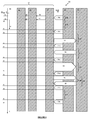
Figure 1 , which shows theRF field 10 and theRF barcode response 12 as a function of time on the horizontal axis, it can be seen that the RF field is initially OFF, but after time t1, it is switched on. The RF barcode is powered-up and activated by the RF field, and within 1ms of t1, begins broadcasting itsUID 14. - As can be seen from
Figure 2 more clearly, theUID 14 is made up of a number of pulses representative of the UID. Eachbit 16 takes 9.44 µs to transmit, so a 128-bit UID takes 1.21 ms to transmit, assuming a bit rate of 106 kbps. Thesleep interval 18, i.e. the wait time betweensuccessive UID transmissions 14, is 3.6ms. - On the other hand, NFC-A tags (or other listen mode devices) work in a Request-Response mode, and therefore wait for an NFC-A Poll Request from an NFC reader device before transmitting the NFC-A Poll Response.
- For the avoidance of doubt, NFC Forum "Type-1 Tag" (T1T), "Type-2 Tag" (T2T) and "Type-4A Tag" (T4AT) are all based on NFC-A technology. As such, the terms "NFC-A tag" and "NFC-A listen mode devices" are essentially the same. NFC-DEP based peer-to-peer (P2P) target devices may also be based on NFC-A technology.
- As such, until the RF barcode leaves the RF field, it will continue to broadcast its UID. Moreover, because the RF barcode cannot accept a power-down command from the reader device, to halt, or pause, the RF barcode's UID transmission, other NFC traffic, for example, between the reader and other NFC-A devices is adversely affected.
- At present, there are no guidelines for reading RF barcode-type devices alongside other NFC-A devices (in reader mode or card emulation mode) and the fact that the RF barcode, by design, repeatedly broadcasts its UID, can cause data collisions or adversely affect the stability of the reader device, which degrades the user experience.
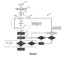
- The reason for this is that the Kovio standard specification, as shown in
Figure 3 , imposes a guard time of 5ms for polling the NFC-A tags. This means that when the RF field is switched on, the RF barcode devices activate within 1ms, whereas other NFC-A devices are not polled until 5ms after switching on the RF field. The problem is that when an RF barcode type device (e.g. a "Kovio tag") is detected by an NFC reader, the NFC reader cannot poll for NFC-A tags. As a result, the NFC reader will switch OFF the RF field upon detection of only RF barcode devices, resulting in a bad user experience because the NFC reader won't detect any NFC-A tags even though NFC-A tags may be present in the RF field. - Referring to
Figure 3 , the sequence commences by switching ON 20 the RF field, whereupon the ISO 14443-3 polling loop protocol is initialized 22. Within 1ms, 24, polling begins, which starts a "seek"procedure 26. During theseek procedure 26, aguard time 28 of5ms 28 is waited-out. If an RF barcode is present in the RF field, i.e. if the NFC reader receives the 1stbit 30 before the expiry of the5ms guard time 28, then the RF barcode is deemed "detected" 32 and the remainder of the UID is obtained 34. - On the other hand, if
5ms guard time 28 expires without detecting an RF barcode, then the NFC reader will proceed to poll for NFC-A devices in theusual way 36. - As can be seen from
Figure 3 , the NFC reader will proceed to poll for NFC-A tags 36 only if it doesn't detect an RF barcode within5ms 28 of switching ON the RF field. - A need therefore exists for a solution that makes it possible for RF barcode-type devices to coexist with other types of NFC devices in an NFC environment, for example, enabling RF barcodes and other ISO 14443-compliant devices to cohabit and interoperate in parallel with a common reader device.
- According to a first aspect of the invention, there is provided a method of connecting an NFC reader to a plurality of NFC devices, the plurality of NFC devices comprising at least one NFC-A device and at least one RF barcode, the method comprising the steps of: detecting and logging the active and sleep intervals of the RF barcode when an RF field is switched on; and synchronizing the transmission and reception of data to, and from, the or each NFC-A device such that transmission and reception of data to, and from, the or each NFC-A device occurs only when the or each RF barcode is in a sleep interval.
- The RF barcode may be a "Kovio" tag.
- Suitably, the step of detecting and logging the active and sleep intervals of the RF barcode occurs by switching on an RF field which is capable of powering-up the RF barcode and by listening for a response from the RF barcode. Upon detection of an RF barcode in the RF field, the transmission of the RF barcode's UID is suitably timed. Suitably, a timer or clock is used to time the start and end of the UID transmissions. The start and end times of the UID transmissions are suitably logged, and the log so produced is suitably stored in a memory device. From the log, the duration and period of the RF barcode's UID transmissions is suitably determinable.
- The detection of RF barcodes is suitably performed prior to the detection of other NFC-A devices. A guard time is suitably employed, say of 5ms duration, during which the NFC reader is configured to search only for RF barcodes, and after which guard time, the NFC reader is configured to search for other NFC-A devices. If no RF barcodes are detected within the guard time, the NFC reader may be adapted to operate in a conventional NFC mode of operation, that is to say, according to the NFC-A standard. However, if an RF barcode is detected within the guard time, the NFC reader is suitably adapted to operate in a synchronous mode according to the invention, that is to say, whereby the exchange of data with NFC-A devices is synchronized to occur only within the sleep intervals of the RF barcode, that is to say, in the intervals between successive UID transmissions of the RF barcode.
- A second aspect of the invention provides an apparatus for connecting an NFC reader to a plurality of NFC devices, the plurality of NFC devices comprising at least one NFC-A device and at least one RF barcode, the apparatus comprising: an RF transceiver, a clock and a processor, the processor comprising: means for detecting the RF barcode when the RF transceiver is active; and means for monitoring the RF barcode's UID transmissions, wherein the clock and processor are together configured to monitor the period and duration of the RF barcode's UID transmissions,, characterised by the processor being configured to poll for and/or to exchange data with the NFC-A device only in the intervals between the end of a first, and the beginning of a second UID transmission by the RF barcode.
- The apparatus may comprise a unitary NFC reader, or in certain embodiments, an RF field capable of powering-up the RF barcode may be produced by a separate source. The RF transceiver suitably comprises a transmitter module and a receiver module, which may be integral with one another, or separate.
- The clock may comprise a system clock of the processor.
- The processor, in one embodiment, comprises hardware, such as a dedicated integrated circuit, or in certain other embodiments, the processor may comprise an application, application layer or software module operable within an operating system of an electronic device, such as a mobile telephone.
- The means for detecting the RF barcode suitably employs the NFC-A standard, whereby a command is broadcast on the RF field. NFC devices present within the RF field, according to the NFC standard, are configured to respond with a response that is detectable by the transceiver of the system.
- In the case of an RF barcode, the response is a UID transmission, and upon detection of the UID, or at least the first bit of the UID, the apparatus is suitably configured to check for the receipt of a complete UID.
- The clock is suitably triggered by the commencement and termination of the receipt of the UID, and the clock start/stop times are suitably stored in a memory device of the apparatus. From the log of clock's start/stop times, the processor is suitably configured to calculate the period of the UID transmissions, that is to say, the interval between successive identifiers therein, such as the start or end of the each UID transmission; and the duration of each UID transmission, that is to say, the interval between the start and end of each UID transmission. From these values, the processor is able to predict when the next UID is likely to be received, but more importantly, when the RF barcode is next going to be inactive, that is to say, not transmitting its UID.
- Upon detection of an RF barcode, therefore, the apparatus configured to begin logging the UID transmissions and to begin predicting the sleep periods of the RF barcode.
- The apparatus is thus able to synchronize its data exchange data with NFC-A devices other than RF barcodes, in the sleep intervals of any resident RF barcodes.
- As such, the invention provides a system and technique which permits communication with NFC-A tags during sleep durations (or intervals) of RF barcodes (Kovio tags) frame periodic transmission. Suitably, therefore, the invention provides a system, method and procedure whereby an NFC reader can poll for, and detect, the presence of NFC-A tags even when an RF barcode (Kovio tag) is also present in the RF field and also detected by the NFC reader.
- Preferred embodiments of the invention shall now be described, by way of example only, with reference to the accompanying drawings in which:
-
Figure 1 is a signaling diagram showing the operation of an RF barcode-type device; -
Figure 2 is a detailed, and extended, view ofFigure 1 ; -
Figure 3 is a schematic flowchart showing the reconciliation of RF barcodes and NFC-A devices in an NFC environment; -
Figure 4 is a schematic system diagram showing the operation of an embodiment of the invention; -
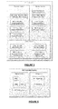
Figure 5 depicts, diagrammatically, an NFC Sub-system for the invention; -
Figure 6 shows the block diagram of NFC Controller System relevant for this invention; and -
Figure 7 describes the complete flow and sequence of the invention. - In
Figure 4 , anNFC environment 50 comprises anNFC reader 52, a RF barcode device 54 and an NFC-A device 56. TheNFC reader 52 comprises anNFC interface 58, a memory device 60, aclock 62 and an RF transceiver 64. At t=0, the host (not shown) initiates 66 theNFC interface 58, which switches on the RF field 68. Within 1ms of t=0, the RF barcode 54 is powered-up and begins transmitting itsUID 70. The duration 72 of theUID 70 is 1.12ms, and the period is 4.72 ms, meaning that the sleep time 74 is 3.6 ms. The RF barcode 54 re-transmits itsUID 70 at regular intervals. - Meanwhile, the reception of the
UID 70 triggers 76 theclock 52, and theclock 52stores 78 the start time ts in the memory 60. When the RF barcode 54 ceases transmitting itsUID 70, theclock 62 is triggered 80 once again, and the end time te is recorded 82 in the memory 60. - At this point, the host (not shown) can interrogate the memory 60 to determine the time tn when the
next UID 70a will be transmitted, that is to say, at te + the sleep time 74, and its duration, which should be equal to te - ts. - Meanwhile, at t=5ms, which may be before or after tn, the
guard period 76 expires and theNFC interface 58 can begin polling for other NFC-A devices 56 present in the RF field 68. - However, because the host (not shown) can determine when the next 70a, and each
subsequent UID transmission A traffic 90 to occur during the sleep intervals 74 of the RF barcode 54. - As can be seen in
Figure 4 , the host (not shown) initiates ahandshake command 90 with the NFC-A device during a sleep interval 74. Thehandshake command 90 includes a frame waiting time 99 for the NFC-A device 56, such that the NFC-A device 56 delays responding 92 until the next sleep interval 74 of the RF barcode 54. As such, theNFC reader 52 is able to initiate and sustain a connection with an NFC-A device 56 in spite of the co-existence of the RF barcode 54 in the RF field 68. - When the
NFC reader 52 wishes to transmit adata packet 94 whose duration will exceed a sleep interval 74, the host (not shown) configures theNFC interface 58 to truncate thepacket 94 to fit within the sleep interval 74. As such, atruncated data packet 94 contains a command instructing the NFC-A device to wait for receipt of asubsequent packet 96, completing the transmission. The NFC-A device can also be configured to act likewise, that is to say, to truncate itsresponse 98 to fit within a sleep interval 74 or to wait until the next available full sleep interval 74 before responding. - Meanwhile, it will be noted that the
clock 62 is being triggered by eachUID 70 transmission, and the log 60 updated in real time. Such a configuration safeguards against asynchronous behavior, for example, where the RF barcode 54 powers-down temporarily (e.g. if it temporarily leaves the RF field 68) or where the RF barcode moves out of range of the RF field 68 altogether. Notably, the system obeys the frame waiting time 99 for NFC-A communications. - It will be appreciated that where, during the initial seek phase, no RF barcodes 54 are detected, the
NFC reader 52 can operate in a standard mode: communicating as per the NFC standard with the NFC-A device or devices alone. - In
Figure 5 is a block diagram showing the NFC interface/sub-system 200 previously described, which comprises a transmit section 100 and a receive section 102. There is also a control section 104, which controls the detection 106 of the sleep intervals 74 and 107 the UID durations 72, and collision resolution modules 108, 110. The NFC-sub system ofFigure 5 resides within the digital section of anNFC controller 58, as shown inFigure 6 , which comprises a CPU 112, memory comprising ROM 114 and RAM 116 and an RF section 118 comprising a transceiver 64. -
Figure 7 is a flow diagram showing the operation of the invention. After the NFC reader switches ON 20 the RF field, it detects 120 the presence of an RF barcode as described in the "Kovio standard specification". If the NFC reader is configured to poll for NFC-A tags 56, it continues to detect the presence of an RF barcode 54 up to the expiry of a5ms guard time 76. - If no RF barcode 54 is detected and the
5ms guard time 76 has expired, theNFC reader 52 proceeds to poll for NFC-A tags 56 as per the NFC-Forum Digital Protocol Specification (Section: NFC-A Technology). - On the other hand, if the
NFC reader 52 detects 120 an RF barcode (i.e. a 128-bit code with a correct CRC is received), then theNFC reader 52 maintains the RF field 68, and tracks theperiodic transmissions 122 of UIDs 70 (128-bit code) as well 124 as the sleep intervals 74 (3.6ms) usinginternal timers 62. In other words, theNFC reader 52 is aware of the timing of theUIDs 70, and when the RF barcode 54 enters the sleep state 74 (i.e. noUID 70 transmission). - The data transfer rate for both RF barcodes and other NFC-A devices is fixed at 106kbps. Since it takes approx. 9.44µs to transmit 1-bit at 106kbps, this means that approximately 381-bits (or at least 47 bytes) can be transmitted or received during each 3.6ms sleep interval 74.
- However, polling for NFC-
A devices 56 by anNFC reader 52 occurs in Request-Response pairs, which requires a frame delay time 99 in either direction as per the NFC-Forum Digital Protocol Specification (Section: NFC-A Technology). - Nevertheless, the
NFC reader 52 is configured to operate in receive-only mode during UID reception intervals (i.e. between ts and te), and so theNFC reader 52 does not transmit (e.g. an NFC-A Request) during UID reception periods. - The
NFC reader 52 also synchronizes aninternal timer NFC reader 52 is able to track the UID sleep duration 74 such that theNFC reader 52 is able to ascertain or determine (predict) when the next sleep tn interval 74 will expire and also when thenext UID 70 will be received. As such, theNFC reader 52 can be configured to transmit NFC-A requests responses - Moreover, and as described previously, the
NFC reader 52 is thus able to collect and maintain NFC-A request and response data transmitted and received during sleep intervals 74. The stored historical data can usefully be used by theNFC reader 52 in subsequent sleep intervals 74 as part of the NFC-A discovery or collision resolution process. - In one embodiment, the
NFC reader 52 is configured to refrain from transmitting an NFC-A request 90 if the associated NFC-A response 92 wouldn't be received from the NFC-A listen device 56 within the same sleep interval 74. In such a case, theNFC reader 52 is able to delay the transmission of such NFC-A requests 90 to a subsequent sleep interval 74 to ensure proper operation. - The NFC reader may resume NFC-A discovery or collision resolution process in subsequent sleep intervals 74. The NFC reader may restart the NFC-A discovery or collision resolution in a sleep interval 74 if it deems necessary. Importantly, the
NFC reader 52 is able to respect the frame delay timings 99 as set forth in the NFC Forum Digital Protocol Specification (Section: NFC-A Technology). - Other modifications to the basic concept of the invention may include the NFC reader 52: storing historical data (from earlier transactions during sleep intervals 74) in subsequent sleep intervals 74; exchanging data with NFC-A listen devices; informing a user about the presence of an RF barcode 54 as well as NFC-
A listen devices 56 in the RF field 68 so that, say, the user can take an appropriate action thereafter. - The RF barcode may transmit 128-bit code or 256-bit code in future generations, without affecting the operation of the invention.
- The system and method of the invention are applicable irrespective of the number of RF barcodes and NFC-A listen devices present in the RF field 68.
- The invention may provide a number of possible technical advantages, including: a method of polling for NFC-A listen devices even when an RF barcode (Kovio Tag) is also present in the RF field and detected by the NFC reader; simplifying the complexity of hardware and/or software implementations in the NFC controller; solving interoperability issues; power efficiency; and a better user experience because a user wouldn't have to remove an RF barcode from the RF field in order to enable the NFC reader to detect NFC-A tags.
- The method of the invention can, as described above, be implemented either in software/firmware or in hardware. The invention is not restricted to the details of the foregoing embodiments, which are merely exemplary of the invention. For example, the NFC reader can be an NFC-enabled mobile phone or an RF communication interface, for example. The NFC-A listen devices can be
Type 1, Type 2 and Type 4A tags/cards; an NFC-enabled mobile phone emulating Kovio tag and/or NFC-A listen devices.
Claims (15)
- A method of connecting an NFC reader to a plurality of NFC devices, the plurality of NFC devices comprising at least one NFC-A device and at least one RF barcode, the method comprising the steps of: detecting and logging the active and sleep intervals of the RF barcode when an RF field is switched on; and synchronizing the transmission and reception of data to, and from, the or each NFC-A device such that transmission and reception of data to, and from, the or each NFC-A device occurs only when the or each RF barcode is in a sleep interval.
- The method of claim 1, wherein the step of detecting and logging the active and sleep intervals of the RF barcode occurs by switching on an RF field which is capable of powering-up the RF barcode and by listening for a response from the RF barcode.
- The method of claim 1 or claim 2, further comprising, upon detection of an RF barcode in the RF field, timing the start and end of each UID transmission by the RF barcode.
- The method of claim 3, further comprising storing the start and end times of the UID transmissions in a log of a memory device.
- The method of claim 3 or claim 4, further comprising calculating the duration and period of the RF barcode's UID transmissions.
- The method of any preceding claim, comprising detecting the presence of RF barcodes prior to the detection of other NFC-A devices.
- The method of claim 6, wherein the detection of the other NFC-A devices is delayed until after expiry of a guard time.
- The method of claim 7, wherein, if no RF barcodes are detected within the guard time, the NFC is configured to operate in a conventional NFC mode of operation.
- The method of claim 7, wherein, if an RF barcode is detected within the guard time, the NFC reader is adapted to operate in a synchronous mode, whereby the exchange of data with NFC-A devices is synchronized to occur only within the intervals between successive UID transmissions of the RF barcode or barcodes.
- The method of any preceding claim, comprising the steps of an NFC reader initiating an NFC interface and switching on an RF field, detecting an RF barcode powered-up by the field, and receiving the barcode's UID; timing and logging the start and end of each UID transmission, and calculating the duration and period of the UID transmissions; the method further comprising predicting the timing of future UID transmissions by the RF barcode based on the logged start and end times of earlier UID transmissions, and synchronizing the transmission and reception of data to and from the NFC-A devices to occur only during the intervals between successive UID transmissions.
- The method of claim 10, wherein the step of predicting the timing of future UID transmissions comprises interrogating the log of earlier UID transmissions and determining, by adding the interval between previously-logged UID end and start times to the end time of a UID transmission.
- The method of claim 10, further comprising the step of truncating the transmission of data to and from the NFC-A device or devices to fit within the UID sleep intervals.
- The method of claim 12, further comprising adding a frame waiting time to the data transmitted to the NFC-A devices, the frame waiting time corresponding to the start of a future sleep interval of the RF barcode, such that the NFC-A device delays the transmission of its response until a specified RF barcode sleep interval.
- An apparatus for connecting an NFC reader to a plurality of NFC devices, the plurality of NFC devices comprising at least one NFC-A device and at least one RF barcode, the apparatus comprising: an RF transceiver, a clock and a processor, the processor comprising: means for detecting the RF barcode when the RF transceiver is active; and means for monitoring the RF barcode's UID transmissions, wherein the clock and processor are together configured to monitor the period and duration of the RF barcode's UID transmissions, characterised by the processor being configured to poll for and/or to exchange data with the NFC-A device only in the intervals between the end of a first, and the beginning of a second UID transmission by the RF barcode.
- The apparatus of claim 14, wherein the clock is triggered by the commencement and termination of the receipt of UIDs from an RF barcode.
Priority Applications (2)
| Application Number | Priority Date | Filing Date | Title |
|---|---|---|---|
| EP13176840.0A EP2827280B1 (en) | 2013-07-17 | 2013-07-17 | System and method for polling NFC-A devices alongside RF barcodes |
| US14/332,994 US9336418B2 (en) | 2013-07-17 | 2014-07-16 | System and method for polling NFC-A devices alongside RF barcode devices |
Applications Claiming Priority (1)
| Application Number | Priority Date | Filing Date | Title |
|---|---|---|---|
| EP13176840.0A EP2827280B1 (en) | 2013-07-17 | 2013-07-17 | System and method for polling NFC-A devices alongside RF barcodes |
Publications (2)
| Publication Number | Publication Date |
|---|---|
| EP2827280A1 true EP2827280A1 (en) | 2015-01-21 |
| EP2827280B1 EP2827280B1 (en) | 2015-11-04 |
Family
ID=48808198
Family Applications (1)
| Application Number | Title | Priority Date | Filing Date |
|---|---|---|---|
| EP13176840.0A Active EP2827280B1 (en) | 2013-07-17 | 2013-07-17 | System and method for polling NFC-A devices alongside RF barcodes |
Country Status (2)
| Country | Link |
|---|---|
| US (1) | US9336418B2 (en) |
| EP (1) | EP2827280B1 (en) |
Cited By (1)
| Publication number | Priority date | Publication date | Assignee | Title |
|---|---|---|---|---|
| CN115297567A (en) * | 2022-09-29 | 2022-11-04 | 广州智慧城市发展研究院 | Connection communication method and system between near field communication chips |
Families Citing this family (8)
| Publication number | Priority date | Publication date | Assignee | Title |
|---|---|---|---|---|
| US9408238B2 (en) | 2014-02-21 | 2016-08-02 | Sony Corporation | Removable conductive layer that shields and/or shorts nodes of an NFC circuit to control transmissions therefrom |
| US9345050B2 (en) * | 2014-02-21 | 2016-05-17 | Sony Corporation | NFC collision avoidance with controllable NFC transmission delay timing |
| US9312921B2 (en) | 2014-02-21 | 2016-04-12 | Sony Corporation | Retrieving/authorizing content on user equipment based on information from connectable accessory with NFC circuit |
| US9531443B2 (en) * | 2014-03-29 | 2016-12-27 | Intel Corporation | Techniques for communication with tag devices |
| US9647884B2 (en) | 2015-02-19 | 2017-05-09 | Qualcomm Incorporated | Near field communication forum listen mode profiles |
| US11791866B2 (en) * | 2018-10-01 | 2023-10-17 | Qualcomm Incorporated | Systems and methods for device coexistence |
| AU2021221518B1 (en) * | 2021-08-24 | 2022-07-28 | Kareela Investment Enterprises Pty Ltd | Monitoring system and method |
| WO2026012130A1 (en) * | 2024-07-09 | 2026-01-15 | Shanghai Xiangcheng Communication Technology Co., Ltd | Pos terminal and control method thereof |
Citations (3)
| Publication number | Priority date | Publication date | Assignee | Title |
|---|---|---|---|---|
| EP1630714A2 (en) * | 2004-08-26 | 2006-03-01 | Fujitsu Limited | Wireless tags |
| EP1959579A1 (en) * | 2005-11-11 | 2008-08-20 | Fujitsu Limited | Electronic tag, and electronic tag system |
| US20090021353A1 (en) * | 2007-02-06 | 2009-01-22 | Aruze Corp. | Control Device, RFID Tag Reading System and RFID Tag Reader |
Family Cites Families (7)
| Publication number | Priority date | Publication date | Assignee | Title |
|---|---|---|---|---|
| US7596152B2 (en) * | 2004-12-07 | 2009-09-29 | Intel Corporation | Apparatus, system and method capable of low duty cycle hierarchical AD HOC networks |
| US8838481B2 (en) * | 2011-07-26 | 2014-09-16 | Golba Llc | Method and system for location based hands-free payment |
| DE102007020296A1 (en) * | 2007-04-30 | 2008-11-13 | Philip Behrens | Device and method for the wireless production of a contact |
| US9380403B2 (en) * | 2010-10-06 | 2016-06-28 | Mastercard International Incorporated | Methods, systems, and computer readable media for provisioning location specific content information to a mobile device |
| US8824961B2 (en) * | 2011-06-28 | 2014-09-02 | Broadcom Corporation | Method and apparatus for reducing NFC multi-protocol polling duration and power consumption |
| US9160415B2 (en) * | 2012-05-01 | 2015-10-13 | Broadcom Corporation | Open-loop frequency lock methods for fast boot-up time |
| US9587487B2 (en) * | 2013-03-12 | 2017-03-07 | Halliburton Energy Services, Inc. | Wellbore servicing tools, systems and methods utilizing near-field communication |
-
2013
- 2013-07-17 EP EP13176840.0A patent/EP2827280B1/en active Active
-
2014
- 2014-07-16 US US14/332,994 patent/US9336418B2/en active Active
Patent Citations (3)
| Publication number | Priority date | Publication date | Assignee | Title |
|---|---|---|---|---|
| EP1630714A2 (en) * | 2004-08-26 | 2006-03-01 | Fujitsu Limited | Wireless tags |
| EP1959579A1 (en) * | 2005-11-11 | 2008-08-20 | Fujitsu Limited | Electronic tag, and electronic tag system |
| US20090021353A1 (en) * | 2007-02-06 | 2009-01-22 | Aruze Corp. | Control Device, RFID Tag Reading System and RFID Tag Reader |
Cited By (1)
| Publication number | Priority date | Publication date | Assignee | Title |
|---|---|---|---|---|
| CN115297567A (en) * | 2022-09-29 | 2022-11-04 | 广州智慧城市发展研究院 | Connection communication method and system between near field communication chips |
Also Published As
| Publication number | Publication date |
|---|---|
| US9336418B2 (en) | 2016-05-10 |
| US20150024683A1 (en) | 2015-01-22 |
| EP2827280B1 (en) | 2015-11-04 |
Similar Documents
| Publication | Publication Date | Title |
|---|---|---|
| EP2827280B1 (en) | System and method for polling NFC-A devices alongside RF barcodes | |
| JP4486126B2 (en) | Multifunctional device capable of short-range communication and operation method thereof | |
| EP2224378B1 (en) | Method for switching an RFID tag from deep sleep to active mode | |
| TW201301794A (en) | Method and apparatus for reducing NFC multi-protocol polling duration and power consumption | |
| US20140073240A1 (en) | Hybrid rf polling loop for nfc device and retry mechanism | |
| EP2565817A1 (en) | Method and apparatus for close proximity device discovery | |
| EP2816501B1 (en) | A near field communication listen device emulating multiple NFC B technology tags | |
| CN105099514B (en) | Method for discovering multiple NFC-B devices by NFC-B reader and corresponding NFC-B reader | |
| JP5042640B2 (en) | Wireless authentication system | |
| CN115134789A (en) | Method for implementing NFC transactions | |
| EP2722790B1 (en) | Coexistence of RF barcodes and other NFC devices | |
| EP3228018B1 (en) | Nfc method and device for communication with improved power harvesting | |
| JP2008182579A (en) | Radio authentication system, and entry/exit control system using the same | |
| US11791866B2 (en) | Systems and methods for device coexistence | |
| CN115333578B (en) | Electronic device and method for operating the electronic device | |
| JP2008182571A (en) | Radio authentication system, and entry/exit control system using the same |
Legal Events
| Date | Code | Title | Description |
|---|---|---|---|
| 17P | Request for examination filed |
Effective date: 20140220 |
|
| AK | Designated contracting states |
Kind code of ref document: A1 Designated state(s): AL AT BE BG CH CY CZ DE DK EE ES FI FR GB GR HR HU IE IS IT LI LT LU LV MC MK MT NL NO PL PT RO RS SE SI SK SM TR |
|
| AX | Request for extension of the european patent |
Extension state: BA ME |
|
| PUAI | Public reference made under article 153(3) epc to a published international application that has entered the european phase |
Free format text: ORIGINAL CODE: 0009012 |
|
| GRAP | Despatch of communication of intention to grant a patent |
Free format text: ORIGINAL CODE: EPIDOSNIGR1 |
|
| INTG | Intention to grant announced |
Effective date: 20150610 |
|
| GRAS | Grant fee paid |
Free format text: ORIGINAL CODE: EPIDOSNIGR3 |
|
| GRAA | (expected) grant |
Free format text: ORIGINAL CODE: 0009210 |
|
| AK | Designated contracting states |
Kind code of ref document: B1 Designated state(s): AL AT BE BG CH CY CZ DE DK EE ES FI FR GB GR HR HU IE IS IT LI LT LU LV MC MK MT NL NO PL PT RO RS SE SI SK SM TR |
|
| REG | Reference to a national code |
Ref country code: GB Ref legal event code: FG4D |
|
| REG | Reference to a national code |
Ref country code: CH Ref legal event code: EP |
|
| REG | Reference to a national code |
Ref country code: AT Ref legal event code: REF Ref document number: 759653 Country of ref document: AT Kind code of ref document: T Effective date: 20151115 |
|
| REG | Reference to a national code |
Ref country code: IE Ref legal event code: FG4D |
|
| REG | Reference to a national code |
Ref country code: DE Ref legal event code: R096 Ref document number: 602013003725 Country of ref document: DE |
|
| REG | Reference to a national code |
Ref country code: NL Ref legal event code: MP Effective date: 20151104 |
|
| REG | Reference to a national code |
Ref country code: LT Ref legal event code: MG4D |
|
| REG | Reference to a national code |
Ref country code: AT Ref legal event code: MK05 Ref document number: 759653 Country of ref document: AT Kind code of ref document: T Effective date: 20151104 |
|
| PG25 | Lapsed in a contracting state [announced via postgrant information from national office to epo] |
Ref country code: NL Free format text: LAPSE BECAUSE OF FAILURE TO SUBMIT A TRANSLATION OF THE DESCRIPTION OR TO PAY THE FEE WITHIN THE PRESCRIBED TIME-LIMIT Effective date: 20151104 Ref country code: IT Free format text: LAPSE BECAUSE OF FAILURE TO SUBMIT A TRANSLATION OF THE DESCRIPTION OR TO PAY THE FEE WITHIN THE PRESCRIBED TIME-LIMIT Effective date: 20151104 Ref country code: LT Free format text: LAPSE BECAUSE OF FAILURE TO SUBMIT A TRANSLATION OF THE DESCRIPTION OR TO PAY THE FEE WITHIN THE PRESCRIBED TIME-LIMIT Effective date: 20151104 Ref country code: ES Free format text: LAPSE BECAUSE OF FAILURE TO SUBMIT A TRANSLATION OF THE DESCRIPTION OR TO PAY THE FEE WITHIN THE PRESCRIBED TIME-LIMIT Effective date: 20151104 Ref country code: IS Free format text: LAPSE BECAUSE OF FAILURE TO SUBMIT A TRANSLATION OF THE DESCRIPTION OR TO PAY THE FEE WITHIN THE PRESCRIBED TIME-LIMIT Effective date: 20160304 Ref country code: HR Free format text: LAPSE BECAUSE OF FAILURE TO SUBMIT A TRANSLATION OF THE DESCRIPTION OR TO PAY THE FEE WITHIN THE PRESCRIBED TIME-LIMIT Effective date: 20151104 Ref country code: NO Free format text: LAPSE BECAUSE OF FAILURE TO SUBMIT A TRANSLATION OF THE DESCRIPTION OR TO PAY THE FEE WITHIN THE PRESCRIBED TIME-LIMIT Effective date: 20160204 |
|
| PG25 | Lapsed in a contracting state [announced via postgrant information from national office to epo] |
Ref country code: FI Free format text: LAPSE BECAUSE OF FAILURE TO SUBMIT A TRANSLATION OF THE DESCRIPTION OR TO PAY THE FEE WITHIN THE PRESCRIBED TIME-LIMIT Effective date: 20151104 Ref country code: AT Free format text: LAPSE BECAUSE OF FAILURE TO SUBMIT A TRANSLATION OF THE DESCRIPTION OR TO PAY THE FEE WITHIN THE PRESCRIBED TIME-LIMIT Effective date: 20151104 Ref country code: LV Free format text: LAPSE BECAUSE OF FAILURE TO SUBMIT A TRANSLATION OF THE DESCRIPTION OR TO PAY THE FEE WITHIN THE PRESCRIBED TIME-LIMIT Effective date: 20151104 Ref country code: PT Free format text: LAPSE BECAUSE OF FAILURE TO SUBMIT A TRANSLATION OF THE DESCRIPTION OR TO PAY THE FEE WITHIN THE PRESCRIBED TIME-LIMIT Effective date: 20160304 Ref country code: RS Free format text: LAPSE BECAUSE OF FAILURE TO SUBMIT A TRANSLATION OF THE DESCRIPTION OR TO PAY THE FEE WITHIN THE PRESCRIBED TIME-LIMIT Effective date: 20151104 Ref country code: PL Free format text: LAPSE BECAUSE OF FAILURE TO SUBMIT A TRANSLATION OF THE DESCRIPTION OR TO PAY THE FEE WITHIN THE PRESCRIBED TIME-LIMIT Effective date: 20151104 Ref country code: SE Free format text: LAPSE BECAUSE OF FAILURE TO SUBMIT A TRANSLATION OF THE DESCRIPTION OR TO PAY THE FEE WITHIN THE PRESCRIBED TIME-LIMIT Effective date: 20151104 Ref country code: GR Free format text: LAPSE BECAUSE OF FAILURE TO SUBMIT A TRANSLATION OF THE DESCRIPTION OR TO PAY THE FEE WITHIN THE PRESCRIBED TIME-LIMIT Effective date: 20160205 |
|
| REG | Reference to a national code |
Ref country code: FR Ref legal event code: PLFP Year of fee payment: 4 |
|
| PG25 | Lapsed in a contracting state [announced via postgrant information from national office to epo] |
Ref country code: CZ Free format text: LAPSE BECAUSE OF FAILURE TO SUBMIT A TRANSLATION OF THE DESCRIPTION OR TO PAY THE FEE WITHIN THE PRESCRIBED TIME-LIMIT Effective date: 20151104 |
|
| REG | Reference to a national code |
Ref country code: DE Ref legal event code: R097 Ref document number: 602013003725 Country of ref document: DE |
|
| PG25 | Lapsed in a contracting state [announced via postgrant information from national office to epo] |
Ref country code: SM Free format text: LAPSE BECAUSE OF FAILURE TO SUBMIT A TRANSLATION OF THE DESCRIPTION OR TO PAY THE FEE WITHIN THE PRESCRIBED TIME-LIMIT Effective date: 20151104 Ref country code: SK Free format text: LAPSE BECAUSE OF FAILURE TO SUBMIT A TRANSLATION OF THE DESCRIPTION OR TO PAY THE FEE WITHIN THE PRESCRIBED TIME-LIMIT Effective date: 20151104 Ref country code: RO Free format text: LAPSE BECAUSE OF FAILURE TO SUBMIT A TRANSLATION OF THE DESCRIPTION OR TO PAY THE FEE WITHIN THE PRESCRIBED TIME-LIMIT Effective date: 20151104 Ref country code: EE Free format text: LAPSE BECAUSE OF FAILURE TO SUBMIT A TRANSLATION OF THE DESCRIPTION OR TO PAY THE FEE WITHIN THE PRESCRIBED TIME-LIMIT Effective date: 20151104 Ref country code: DK Free format text: LAPSE BECAUSE OF FAILURE TO SUBMIT A TRANSLATION OF THE DESCRIPTION OR TO PAY THE FEE WITHIN THE PRESCRIBED TIME-LIMIT Effective date: 20151104 |
|
| PLBE | No opposition filed within time limit |
Free format text: ORIGINAL CODE: 0009261 |
|
| STAA | Information on the status of an ep patent application or granted ep patent |
Free format text: STATUS: NO OPPOSITION FILED WITHIN TIME LIMIT |
|
| 26N | No opposition filed |
Effective date: 20160805 |
|
| PG25 | Lapsed in a contracting state [announced via postgrant information from national office to epo] |
Ref country code: SI Free format text: LAPSE BECAUSE OF FAILURE TO SUBMIT A TRANSLATION OF THE DESCRIPTION OR TO PAY THE FEE WITHIN THE PRESCRIBED TIME-LIMIT Effective date: 20151104 |
|
| PG25 | Lapsed in a contracting state [announced via postgrant information from national office to epo] |
Ref country code: BE Free format text: LAPSE BECAUSE OF FAILURE TO SUBMIT A TRANSLATION OF THE DESCRIPTION OR TO PAY THE FEE WITHIN THE PRESCRIBED TIME-LIMIT Effective date: 20151104 |
|
| REG | Reference to a national code |
Ref country code: CH Ref legal event code: PL |
|
| PG25 | Lapsed in a contracting state [announced via postgrant information from national office to epo] |
Ref country code: MC Free format text: LAPSE BECAUSE OF FAILURE TO SUBMIT A TRANSLATION OF THE DESCRIPTION OR TO PAY THE FEE WITHIN THE PRESCRIBED TIME-LIMIT Effective date: 20151104 |
|
| PG25 | Lapsed in a contracting state [announced via postgrant information from national office to epo] |
Ref country code: CH Free format text: LAPSE BECAUSE OF NON-PAYMENT OF DUE FEES Effective date: 20160731 Ref country code: LI Free format text: LAPSE BECAUSE OF NON-PAYMENT OF DUE FEES Effective date: 20160731 |
|
| REG | Reference to a national code |
Ref country code: IE Ref legal event code: MM4A |
|
| REG | Reference to a national code |
Ref country code: FR Ref legal event code: PLFP Year of fee payment: 5 |
|
| PG25 | Lapsed in a contracting state [announced via postgrant information from national office to epo] |
Ref country code: IE Free format text: LAPSE BECAUSE OF NON-PAYMENT OF DUE FEES Effective date: 20160717 |
|
| PG25 | Lapsed in a contracting state [announced via postgrant information from national office to epo] |
Ref country code: LU Free format text: LAPSE BECAUSE OF NON-PAYMENT OF DUE FEES Effective date: 20160717 |
|
| GBPC | Gb: european patent ceased through non-payment of renewal fee |
Effective date: 20170717 |
|
| PG25 | Lapsed in a contracting state [announced via postgrant information from national office to epo] |
Ref country code: GB Free format text: LAPSE BECAUSE OF NON-PAYMENT OF DUE FEES Effective date: 20170717 |
|
| PG25 | Lapsed in a contracting state [announced via postgrant information from national office to epo] |
Ref country code: HU Free format text: LAPSE BECAUSE OF FAILURE TO SUBMIT A TRANSLATION OF THE DESCRIPTION OR TO PAY THE FEE WITHIN THE PRESCRIBED TIME-LIMIT; INVALID AB INITIO Effective date: 20130717 |
|
| REG | Reference to a national code |
Ref country code: FR Ref legal event code: PLFP Year of fee payment: 6 |
|
| PG25 | Lapsed in a contracting state [announced via postgrant information from national office to epo] |
Ref country code: MK Free format text: LAPSE BECAUSE OF FAILURE TO SUBMIT A TRANSLATION OF THE DESCRIPTION OR TO PAY THE FEE WITHIN THE PRESCRIBED TIME-LIMIT Effective date: 20151104 Ref country code: CY Free format text: LAPSE BECAUSE OF FAILURE TO SUBMIT A TRANSLATION OF THE DESCRIPTION OR TO PAY THE FEE WITHIN THE PRESCRIBED TIME-LIMIT Effective date: 20151104 Ref country code: MT Free format text: LAPSE BECAUSE OF NON-PAYMENT OF DUE FEES Effective date: 20160731 |
|
| PG25 | Lapsed in a contracting state [announced via postgrant information from national office to epo] |
Ref country code: BG Free format text: LAPSE BECAUSE OF FAILURE TO SUBMIT A TRANSLATION OF THE DESCRIPTION OR TO PAY THE FEE WITHIN THE PRESCRIBED TIME-LIMIT Effective date: 20151104 |
|
| PG25 | Lapsed in a contracting state [announced via postgrant information from national office to epo] |
Ref country code: AL Free format text: LAPSE BECAUSE OF FAILURE TO SUBMIT A TRANSLATION OF THE DESCRIPTION OR TO PAY THE FEE WITHIN THE PRESCRIBED TIME-LIMIT Effective date: 20151104 Ref country code: TR Free format text: LAPSE BECAUSE OF FAILURE TO SUBMIT A TRANSLATION OF THE DESCRIPTION OR TO PAY THE FEE WITHIN THE PRESCRIBED TIME-LIMIT Effective date: 20151104 |
|
| PGFP | Annual fee paid to national office [announced via postgrant information from national office to epo] |
Ref country code: FR Payment date: 20200623 Year of fee payment: 8 |
|
| PG25 | Lapsed in a contracting state [announced via postgrant information from national office to epo] |
Ref country code: FR Free format text: LAPSE BECAUSE OF NON-PAYMENT OF DUE FEES Effective date: 20210731 |
|
| PGFP | Annual fee paid to national office [announced via postgrant information from national office to epo] |
Ref country code: DE Payment date: 20250620 Year of fee payment: 13 |