EP2827204A2 - Gas turbine engine controller with event trigger - Google Patents
Gas turbine engine controller with event trigger Download PDFInfo
- Publication number
- EP2827204A2 EP2827204A2 EP14176115.5A EP14176115A EP2827204A2 EP 2827204 A2 EP2827204 A2 EP 2827204A2 EP 14176115 A EP14176115 A EP 14176115A EP 2827204 A2 EP2827204 A2 EP 2827204A2
- Authority
- EP
- European Patent Office
- Prior art keywords
- executions
- current
- mbc
- feedback control
- controller
- Prior art date
- Legal status (The legal status is an assumption and is not a legal conclusion. Google has not performed a legal analysis and makes no representation as to the accuracy of the status listed.)
- Granted
Links
Images

Classifications
-
- F—MECHANICAL ENGINEERING; LIGHTING; HEATING; WEAPONS; BLASTING
- F02—COMBUSTION ENGINES; HOT-GAS OR COMBUSTION-PRODUCT ENGINE PLANTS
- F02C—GAS-TURBINE PLANTS; AIR INTAKES FOR JET-PROPULSION PLANTS; CONTROLLING FUEL SUPPLY IN AIR-BREATHING JET-PROPULSION PLANTS
- F02C9/00—Controlling gas-turbine plants; Controlling fuel supply in air- breathing jet-propulsion plants
-
- G—PHYSICS
- G05—CONTROLLING; REGULATING
- G05B—CONTROL OR REGULATING SYSTEMS IN GENERAL; FUNCTIONAL ELEMENTS OF SUCH SYSTEMS; MONITORING OR TESTING ARRANGEMENTS FOR SUCH SYSTEMS OR ELEMENTS
- G05B17/00—Systems involving the use of models or simulators of said systems
- G05B17/02—Systems involving the use of models or simulators of said systems electric
Definitions
- the subject matter disclosed herein relates to a gas turbine engine controller and, more particularly, to a gas turbine engine controller with an event trigger providing for reduced number of control executions.
- a gas turbine engine may include a compressor, a combustor and a turbine section.
- the compressor compresses inlet air and outputs the compressed inlet air to the combustor.
- the combustor mixes the compressed inlet air with fuel and ignites the mixture to produce high temperature and high pressure fluids.
- the high temperature and high pressure fluids are directed to the turbine section where they are expanded to generate the mechanical energy.
- the gas turbine engine may further include multiple control and feedback control systems to monitor, control and if necessary correct operations of the gas turbine engine.
- the control and feedback control systems often employ model based control (MBC) functionality in performing the monitoring, controlling and correcting of the gas turbine operations.
- MBC model based control
- this involves periodically measuring states of the gas turbine engine, applying appropriate controllers and then generating and employing feedback information via actuators.
- the gas turbine engine could be running at a stable operation point, it may require little or no attention. In such cases, the MBC functionality may be unnecessary.
- a feedback control system includes a controller to control an operation of a motive element in accordance with current and previous measured states.
- the controller includes a servo, a processor and an event trigger controller.
- the event trigger controller is configured to cause the processor to command the servo to perform model based control (MBC) executions in an event a difference between the current and previous measured states exceeds a threshold based on the previous measured state or the current measured state exceeds a limit, and skip the MBC executions in an event the difference does not exceed the threshold and the current measured state does not exceed the limit.
- MBC model based control
- a feedback control system of a gas turbine engine includes a controller to control an operation of the gas turbine engine in accordance with current and previous measured states.
- the controller includes a servo, a processor and a computer readable medium on which executable instructions are stored.
- the executable instructions When executed, the executable instructions cause the processor to command the servo to perform model based control (MBC) executions in an event a difference between the current and previous measured states exceeds a threshold or the current measured state exceeds a limit; and to command the servo to skip the MBC executions in an event the difference does not exceed the threshold and the current measured state does not exceed the limit.
- MBC model based control
- a gas turbine engine includes a compressor-combustor-turbine (CCT) system by which mechanical energy is generated from combustion of compressed inlet air and fuel and a feedback control system including a measurement unit configured to measure a state of the CCT system, a controller configured to control an operation of the CCT system in accordance with current and previous measured states and a feedback unit configured to provide feedback control information to the controller.
- the controller includes a servo, a processor and a computer readable medium on which executable instructions are stored.
- the executable instructions When executed, the executable instructions cause the processor to command the servo to perform model based control (MBC) executions in an event a difference between the current and previous measured states exceeds a threshold or the current measured state exceeds a limit; and to command the servo to skip the MBC executions in an event the difference does not exceed the threshold and the current measured state does not exceed the limit.
- MBC model based control
- event trigger control is applied in gas turbine engine operation along with or in addition to model based control (MBC) in order to eliminate or at least reduce a number of MBC executions.
- MBC model based control
- the present approach differs from prior approaches where MBC functionality is periodically executed for each time step while still sustaining high performance gas turbine operations.
- the MBC functionality is not executed for each time step if a state condition of the gas turbine engine does not change (e.g., if the gas turbine engine is operating at steady state). Rather, the MBC is calculated and executed when the state condition changes.
- the motive element may be, for example, a gas turbine engine 10.
- the gas turbine engine 10 includes a compressor-combustor-turbine (CCT) system 11 and a feedback control system 20.
- the CCT system 11 is configured to generate mechanical energy from combustion of compressed inlet air and fuel and includes a compressor 12, a combustor 13 and a turbine section 14.
- the compressor 12 compresses inlet air and outputs the compressed inlet air to the combustor 13.
- the combustor 13 mixes the compressed inlet air with fuel and ignites the mixture to produce high temperature and high pressure fluids.
- the high temperature and high pressure fluids are directed to the turbine section 14 where they are expanded to generate the mechanical energy.
- the feedback control system 20 is operably coupled to the CCT system 11 and is provided to control various operations of the CCT system 11.
- the feedback control system 20 includes a measurement unit 21, a controller 22 and a feedback control unit 23.
- the measurement unit 21 is configured to periodically measure an operational state of the CCT system 11.
- the controller 22 is configured to control an operation of the CCT system 11 in accordance with the measured operational state of the CCT system 11.
- the feedback control unit 23 is configured to provide feedback control information to the controller 22 so that a performance of the controller 22 can be monitored and improved from iteration to iteration.
- the measurement unit 21 may include a clock or timing element 210 that governs when the measurement unit 21 periodically measures the operational state of the CCT system 11. Although illustrated as being a component of the measurement unit 21, it is to be understood in accordance with alternative embodiments that the clock or timing element 210 may be provided in the measurement unit 21, the controller 22, the feedback control unit 23, as another element of the feedback control system 20 or as a stand-alone element.
- the controller 22 includes a servo element 221, a processor 222 and a computer readable medium 223.
- the computer readable medium 223 may be a storage unit or database on which executable instructions are stored.
- the executable instructions may be embodied as software, hardware or a combination thereof.
- the executable instructions and cooperatively define an event trigger controller 224.
- the executable instructions When executed, the executable instructions cause the processor 222 to command the servo element 221 to perform model based control (MBC) executions or to skip the performance of the MBC executions.
- MBC model based control
- MBC executions may include but are not limited to fuel control executions (i.e., a modulation of relative amounts of compressed air and fuel to be combusted in the combustor 13), inlet guide vane (IGV) control executions (i.e., control of IGV angles in an inlet of the compressor 12) and fire temperature control executions (i.e., control of firing temperatures within the combustor 13, the turbine section 14 and, where applicable, a transition zone fluidly interposed between the combustor 13 and the turbine 14).
- fuel control executions i.e., a modulation of relative amounts of compressed air and fuel to be combusted in the combustor 13
- IGV inlet guide vane
- fire temperature control executions i.e., control of firing temperatures within the combustor 13, the turbine section 14 and, where applicable, a transition zone fluidly interposed between the combustor 13 and the turbine 14.
- the executable instructions cause the processor 222 to calculate MBC executions and to command the servo element 221 to perform the calculated MBC executions in an event the measured current operational state of the CCT system 11 (as determined by the measurement unit 21) is unstable relative to a previous measurement. Conversely, the executable instructions cause the processor 222 to command the servo element 221 to skip the MBC executions in an event the measured current operational state of the CCT system 11 (as determined by the measurement unit 21) is stable relative to the previous measurement.
- the term “unstable” shall refer to a change in an operational state of the CCT system 11 from a previous measurement to a current measurement whereas the term “stable” shall refer to a case where the operational state of the CCT system 11 is unchanged from the previous measurement to the current measurement.
- the current operational state of the CCT system 11 is considered unstable if the current operational state is determined by the measurement unit 21 to have changed from the previously measured state.
- a change in the operational state of the CCT system 11 from the previous measurement to the current measurement that would indicate instability may be small or large in accordance with predefined rules and algorithms. That is, a degree of change from the previous measurement to the current measurement that would be indicative of instability may be defined as any change beyond a predefined threshold or a predefined range of thresholds. Conversely, a degree of change that would be indicative of stability may be defined as any change that does not exceed the predefined threshold or the predefined range of thresholds.
- the predefined threshold and the predefined range of thresholds are manually or automatically variable in accordance with various considerations including, but not limited to, costs, current and/or historical trends and current operational conditions.
- the executable instructions may cause the processor 222 to calculate MBC executions and to command the servo element 221 to perform the calculated MBC executions perform model based control (MBC) executions in an event a difference between the measured current operational state and the previous measurement exceeds a predefined threshold that is based on the previous measurement or in an event the current measured state exceeds a predefined limit. Furthermore, the executable instructions may cause the processor 222 to skip the MBC calculations and executions in an event the difference does not exceed the predefined threshold and the current measured state does not exceed the predefined limit. In these and other embodiments, the measured current operational state and the previous measurement may respectively correspond to consecutive time steps as defined by the clock or timing element 210.
- MBC model based control
- a CCT system 11 may have a firing temperature of 700°F in a given time step (T1). With such a firing temperature, the executable instructions may set the predefined threshold as being 7°F or 1% of the previous firing temperature. In this case, if the firing temperature of the CCT system 11 is determined to be 708°F at the next time step (T2), the MBC calculations and executions will be performed but if the firing temperature is only 706°F, the MBC calculations and executions will be skipped.
- the MBC calculations and executions may be skipped due to the firing temperature being only 706°F at time step T2 but will be performed at time step T3 due to the predefined limit being exceeded even if the firing temperature increase from T2 to T3 is still less than the predefined threshold.
- a periodicity of the operation of the measurement unit 21 may be controlled by the processor 222 or the clock or timing element 210 and may be varied in accordance with multiple design and cost considerations. In general, it is to be understood that the shorter the periodicity of the operation of the measurement unit 21, the more control the feedback control system 20 will exert over the CCT system 11. On the other hand, a longer periodicity may be associated with less control of the CCT system 11 by the feedback control system 20.
- the executable instructions may cause the processor 222 to identify that the operational state of the CCT system 11 is approaching the predefined limit and that trends suggest that the predefined limit will be exceeded within a certain number of time steps. In these cases, the executable instructions can cause the processor 222 to lower the predefined threshold or the predefined limit or to calculate and perform the MBC executions even if neither of the predefined threshold or the predefined limit is exceeded in the state measurement at the next time step.
- the above-mentioned predefined limit and predefined threshold are set in accordance with a previous measurement of the state of the CCT system 11.
- a determination is made that a current time is a time for measuring the operational state (i.e., the state condition) of the CCT system 11 in accordance with the periodicity established by the measurement unit 21.
- a current operational state of the CCT system 11 will be measured by the measurement unit 21 at operation 33.
- a determination is made as to whether a difference between the current operational state of the CCT system 11 and the previous measurement exceeds the predefined threshold.
- control proceeds to operation 37.
- a determination is made as to whether the current operational state of the CCT system 11 exceeds the predefined limit at operation 35.
- control proceeds to operation 37.
- a determination is made as to whether trends suggest that the predefined threshold or the predefined limit will be expected to be exceeded shortly at operation 36. In an event this determination is negative, control reverts to operations 30 and 31 at which point the predefined threshold and predefined limit are reset. However, in an event the determination is affirmative, control proceeds to operation 37.
- the executable instructions i.e., the event trigger controller 2214 cause the processor 222 to calculate MBC executions.
- the executable instructions cause the processor 222 to command the servo element 221 to perform the calculated MBC executions.
- the feedback control unit 23 provides feedback control information to the controller 22 so that a performance of the controller 22 can be monitored and improved from iteration to iteration. Subsequently, control returns to operations 30 and 31 at which point the predefined threshold and predefined limit are reset.
- a technical effect of the embodiments described herein is that event trigger control is applied in gas turbine engine operation along with or in addition to MBC in order to eliminate or at least reduce a number of MBC executions.
- the use of the event trigger control results in MBC functionality not being executed for each time step if a state condition of the gas turbine engine does not change (e.g., if the gas turbine engine is operating at steady state). Rather, the MBC is calculated and executed when the state condition changes.
Landscapes
- Engineering & Computer Science (AREA)
- Chemical & Material Sciences (AREA)
- Combustion & Propulsion (AREA)
- Physics & Mathematics (AREA)
- General Physics & Mathematics (AREA)
- Automation & Control Theory (AREA)
- Mechanical Engineering (AREA)
- General Engineering & Computer Science (AREA)
- Control Of Turbines (AREA)
- Control Of Electric Motors In General (AREA)
Abstract
Description
- The subject matter disclosed herein relates to a gas turbine engine controller and, more particularly, to a gas turbine engine controller with an event trigger providing for reduced number of control executions.
- A gas turbine engine may include a compressor, a combustor and a turbine section. The compressor compresses inlet air and outputs the compressed inlet air to the combustor. The combustor mixes the compressed inlet air with fuel and ignites the mixture to produce high temperature and high pressure fluids. The high temperature and high pressure fluids are directed to the turbine section where they are expanded to generate the mechanical energy. The gas turbine engine may further include multiple control and feedback control systems to monitor, control and if necessary correct operations of the gas turbine engine.
- The control and feedback control systems often employ model based control (MBC) functionality in performing the monitoring, controlling and correcting of the gas turbine operations. Typically, this involves periodically measuring states of the gas turbine engine, applying appropriate controllers and then generating and employing feedback information via actuators. However, since the gas turbine engine could be running at a stable operation point, it may require little or no attention. In such cases, the MBC functionality may be unnecessary.
- According to one aspect of the invention, a feedback control system is provided and includes a controller to control an operation of a motive element in accordance with current and previous measured states. The controller includes a servo, a processor and an event trigger controller. The event trigger controller is configured to cause the processor to command the servo to perform model based control (MBC) executions in an event a difference between the current and previous measured states exceeds a threshold based on the previous measured state or the current measured state exceeds a limit, and skip the MBC executions in an event the difference does not exceed the threshold and the current measured state does not exceed the limit.
- According to another aspect of the invention, a feedback control system of a gas turbine engine is provided and includes a controller to control an operation of the gas turbine engine in accordance with current and previous measured states. The controller includes a servo, a processor and a computer readable medium on which executable instructions are stored. When executed, the executable instructions cause the processor to command the servo to perform model based control (MBC) executions in an event a difference between the current and previous measured states exceeds a threshold or the current measured state exceeds a limit; and to command the servo to skip the MBC executions in an event the difference does not exceed the threshold and the current measured state does not exceed the limit.
- According to yet another aspect of the invention, a gas turbine engine is provided and includes a compressor-combustor-turbine (CCT) system by which mechanical energy is generated from combustion of compressed inlet air and fuel and a feedback control system including a measurement unit configured to measure a state of the CCT system, a controller configured to control an operation of the CCT system in accordance with current and previous measured states and a feedback unit configured to provide feedback control information to the controller. The controller includes a servo, a processor and a computer readable medium on which executable instructions are stored. When executed, the executable instructions cause the processor to command the servo to perform model based control (MBC) executions in an event a difference between the current and previous measured states exceeds a threshold or the current measured state exceeds a limit; and to command the servo to skip the MBC executions in an event the difference does not exceed the threshold and the current measured state does not exceed the limit.
- These and other advantages and features will become more apparent from the following description taken in conjunction with the drawings.
- The subject matter, which is regarded as the invention, is particularly pointed out and distinctly claimed in the claims at the conclusion of the specification. The foregoing and other features, and advantages of the invention are apparent from the following detailed description taken in conjunction with the accompanying drawings in which:
-
FIG. 1 is a schematic diagram of a gas turbine engine; and -
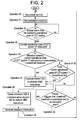
FIG. 2 is a schematic flow diagram of an operation of the gas turbine engine. - The detailed description explains embodiments of the invention, together with advantages and features, by way of example with reference to the drawings.
- As described below, event trigger control is applied in gas turbine engine operation along with or in addition to model based control (MBC) in order to eliminate or at least reduce a number of MBC executions. The present approach differs from prior approaches where MBC functionality is periodically executed for each time step while still sustaining high performance gas turbine operations. In accordance with the present approach, the MBC functionality is not executed for each time step if a state condition of the gas turbine engine does not change (e.g., if the gas turbine engine is operating at steady state). Rather, the MBC is calculated and executed when the state condition changes.
- With reference to
FIG. 1 , a motive element is provided. The motive element may be, for example, agas turbine engine 10. As shown inFIG. 1 , thegas turbine engine 10 includes a compressor-combustor-turbine (CCT)system 11 and afeedback control system 20. TheCCT system 11 is configured to generate mechanical energy from combustion of compressed inlet air and fuel and includes acompressor 12, acombustor 13 and aturbine section 14. Thecompressor 12 compresses inlet air and outputs the compressed inlet air to thecombustor 13. Thecombustor 13 mixes the compressed inlet air with fuel and ignites the mixture to produce high temperature and high pressure fluids. The high temperature and high pressure fluids are directed to theturbine section 14 where they are expanded to generate the mechanical energy. - The
feedback control system 20 is operably coupled to theCCT system 11 and is provided to control various operations of theCCT system 11. Thefeedback control system 20 includes ameasurement unit 21, acontroller 22 and afeedback control unit 23. Themeasurement unit 21 is configured to periodically measure an operational state of theCCT system 11. Thecontroller 22 is configured to control an operation of theCCT system 11 in accordance with the measured operational state of theCCT system 11. Thefeedback control unit 23 is configured to provide feedback control information to thecontroller 22 so that a performance of thecontroller 22 can be monitored and improved from iteration to iteration. - The
measurement unit 21 may include a clock ortiming element 210 that governs when themeasurement unit 21 periodically measures the operational state of theCCT system 11. Although illustrated as being a component of themeasurement unit 21, it is to be understood in accordance with alternative embodiments that the clock ortiming element 210 may be provided in themeasurement unit 21, thecontroller 22, thefeedback control unit 23, as another element of thefeedback control system 20 or as a stand-alone element. - The
controller 22 includes aservo element 221, aprocessor 222 and a computerreadable medium 223. The computerreadable medium 223 may be a storage unit or database on which executable instructions are stored. The executable instructions may be embodied as software, hardware or a combination thereof. Thus, the executable instructions and cooperatively define anevent trigger controller 224. When executed, the executable instructions cause theprocessor 222 to command theservo element 221 to perform model based control (MBC) executions or to skip the performance of the MBC executions. - In accordance with embodiments, MBC executions may include but are not limited to fuel control executions (i.e., a modulation of relative amounts of compressed air and fuel to be combusted in the combustor 13), inlet guide vane (IGV) control executions (i.e., control of IGV angles in an inlet of the compressor 12) and fire temperature control executions (i.e., control of firing temperatures within the
combustor 13, theturbine section 14 and, where applicable, a transition zone fluidly interposed between thecombustor 13 and the turbine 14). - More particularly, the executable instructions cause the
processor 222 to calculate MBC executions and to command theservo element 221 to perform the calculated MBC executions in an event the measured current operational state of the CCT system 11 (as determined by the measurement unit 21) is unstable relative to a previous measurement. Conversely, the executable instructions cause theprocessor 222 to command theservo element 221 to skip the MBC executions in an event the measured current operational state of the CCT system 11 (as determined by the measurement unit 21) is stable relative to the previous measurement. For purposes of clarity and brevity, the term "unstable" shall refer to a change in an operational state of theCCT system 11 from a previous measurement to a current measurement whereas the term "stable" shall refer to a case where the operational state of theCCT system 11 is unchanged from the previous measurement to the current measurement. Thus, the current operational state of theCCT system 11 is considered unstable if the current operational state is determined by themeasurement unit 21 to have changed from the previously measured state. - It is to be understood that a change in the operational state of the
CCT system 11 from the previous measurement to the current measurement that would indicate instability may be small or large in accordance with predefined rules and algorithms. That is, a degree of change from the previous measurement to the current measurement that would be indicative of instability may be defined as any change beyond a predefined threshold or a predefined range of thresholds. Conversely, a degree of change that would be indicative of stability may be defined as any change that does not exceed the predefined threshold or the predefined range of thresholds. In any case, it is to be further understood that the predefined threshold and the predefined range of thresholds are manually or automatically variable in accordance with various considerations including, but not limited to, costs, current and/or historical trends and current operational conditions. - In accordance with embodiments, the executable instructions may cause the
processor 222 to calculate MBC executions and to command theservo element 221 to perform the calculated MBC executions perform model based control (MBC) executions in an event a difference between the measured current operational state and the previous measurement exceeds a predefined threshold that is based on the previous measurement or in an event the current measured state exceeds a predefined limit. Furthermore, the executable instructions may cause theprocessor 222 to skip the MBC calculations and executions in an event the difference does not exceed the predefined threshold and the current measured state does not exceed the predefined limit. In these and other embodiments, the measured current operational state and the previous measurement may respectively correspond to consecutive time steps as defined by the clock ortiming element 210. - As an example, a
CCT system 11 may have a firing temperature of 700°F in a given time step (T1). With such a firing temperature, the executable instructions may set the predefined threshold as being 7°F or 1% of the previous firing temperature. In this case, if the firing temperature of theCCT system 11 is determined to be 708°F at the next time step (T2), the MBC calculations and executions will be performed but if the firing temperature is only 706°F, the MBC calculations and executions will be skipped. By a similar token, if the predefined limit is 709°F and theCCT system 11 has a steadily increasing firing temperature because it is not operating at steady state, the MBC calculations and executions may be skipped due to the firing temperature being only 706°F at time step T2 but will be performed at time step T3 due to the predefined limit being exceeded even if the firing temperature increase from T2 to T3 is still less than the predefined threshold. - A periodicity of the operation of the
measurement unit 21 may be controlled by theprocessor 222 or the clock ortiming element 210 and may be varied in accordance with multiple design and cost considerations. In general, it is to be understood that the shorter the periodicity of the operation of themeasurement unit 21, the more control thefeedback control system 20 will exert over theCCT system 11. On the other hand, a longer periodicity may be associated with less control of theCCT system 11 by thefeedback control system 20. - In accordance with further embodiments, the executable instructions may cause the
processor 222 to identify that the operational state of theCCT system 11 is approaching the predefined limit and that trends suggest that the predefined limit will be exceeded within a certain number of time steps. In these cases, the executable instructions can cause theprocessor 222 to lower the predefined threshold or the predefined limit or to calculate and perform the MBC executions even if neither of the predefined threshold or the predefined limit is exceeded in the state measurement at the next time step. - With reference to
FIG. 2 , an operation of thegas turbine engine 10 will now be described. Initially, atoperations 30 and 31, the above-mentioned predefined limit and predefined threshold are set in accordance with a previous measurement of the state of theCCT system 11. Then, atoperation 32, a determination is made that a current time is a time for measuring the operational state (i.e., the state condition) of theCCT system 11 in accordance with the periodicity established by themeasurement unit 21. In an event the determination is affirmed, a current operational state of theCCT system 11 will be measured by themeasurement unit 21 atoperation 33. Subsequently, atoperation 34, a determination is made as to whether a difference between the current operational state of theCCT system 11 and the previous measurement exceeds the predefined threshold. - In an event the difference exceeds the predefined threshold, control proceeds to operation 37. On the other hand, in an event the difference does not exceed the predefined threshold, a determination is made as to whether the current operational state of the
CCT system 11 exceeds the predefined limit atoperation 35. In an event the predefined limit is exceeded, control proceeds to operation 37. On the other hand, in an event the predefined limit is not exceeded, a determination is made as to whether trends suggest that the predefined threshold or the predefined limit will be expected to be exceeded shortly atoperation 36. In an event this determination is negative, control reverts tooperations 30 and 31 at which point the predefined threshold and predefined limit are reset. However, in an event the determination is affirmative, control proceeds to operation 37. - As shown in
FIG. 2 , at operation 37, the executable instructions (i.e., the event trigger controller 224) cause theprocessor 222 to calculate MBC executions. Then, atoperation 38, the executable instructions cause theprocessor 222 to command theservo element 221 to perform the calculated MBC executions. Next, atoperation 39, thefeedback control unit 23 provides feedback control information to thecontroller 22 so that a performance of thecontroller 22 can be monitored and improved from iteration to iteration. Subsequently, control returns tooperations 30 and 31 at which point the predefined threshold and predefined limit are reset. - In accordance with aspects of the invention, a technical effect of the embodiments described herein is that event trigger control is applied in gas turbine engine operation along with or in addition to MBC in order to eliminate or at least reduce a number of MBC executions. The use of the event trigger control results in MBC functionality not being executed for each time step if a state condition of the gas turbine engine does not change (e.g., if the gas turbine engine is operating at steady state). Rather, the MBC is calculated and executed when the state condition changes.
- While the invention has been described in detail in connection with only a limited number of embodiments, it should be readily understood that the invention is not limited to such disclosed embodiments. Rather, the invention can be modified to incorporate any number of variations, alterations, substitutions or equivalent arrangements not heretofore described, but which are commensurate with the spirit and scope of the invention. Additionally, while various embodiments of the invention have been described, it is to be understood that aspects of the invention may include only some of the described embodiments. Accordingly, the invention is not to be seen as limited by the foregoing description, but is only limited by the scope of the appended claims.
- Various aspects and embodiments of the present invention are defined by the following numbered clauses:
- 1. A feedback control system, comprising:
- a controller to control an operation of a motive element in accordance with current and previous measured states,
- the controller including a servo, a processor and an event trigger controller,
- the event trigger controller being configured to cause the processor to command the servo to:
- perform model based control (MBC) executions in an event a difference between the current and previous measured states exceeds a threshold based on the previous measured state or the current measured state exceeds a limit, and
- skip the MBC executions in an event the difference does not exceed the threshold and the current measured state does not exceed the limit.
- 2. The feedback control system according to clause 1, wherein the current and previous measured states respectively correspond to consecutive time steps.
- 3. The feedback control system according to any preceding clause, further comprising:
- a measurement unit to measure the state of the gas turbine engine; and
- a feedback unit to provide feedback control information to the controller.
- 4. The feedback control system according to any preceding clause, wherein the measurement unit periodically measures the state of the gas turbine engine.
- 5. The feedback control system according to any preceding clause, wherein the event trigger controller is further configured to cause the processor to calculate the MBC executions.
- 6. The feedback control system according to any preceding clause, wherein the MBC executions comprise fuel control executions, inlet guide vane (IGV) control executions and fire temperature control executions.
- 7. The feedback control system according to any preceding clause, wherein the threshold comprises a range of thresholds.
- 8. The feedback control system according to any preceding clause, wherein the limit comprises one of an upper limit and a lower limit.
- 9. The feedback control system according to any preceding clause, wherein the motive element comprises a gas turbine engine.
- 10. A feedback control system of a gas turbine engine, comprising:
- a controller to control an operation of the gas turbine engine in accordance with current and previous measured states,
- the controller including a servo, a processor and a computer readable medium on which executable instructions are stored, and,
- when executed, the executable instructions cause the processor to:
- command the servo to perform model based control (MBC) executions in an event a difference between the current and previous measured states exceeds a threshold or the current measured state exceeds a limit; and to
- command the servo to skip the MBC executions in an event the difference does not exceed the threshold and the current measured state does not exceed the limit.
- 11. The feedback control system according to any preceding clause, wherein the current and previous measured states respectively correspond to consecutive time steps.
- 12. The feedback control system according to any preceding clause, further comprising:
- a measurement unit to measure the state of the gas turbine engine; and
- a feedback unit to provide feedback control information to the controller.
- 13. The feedback control system according to any preceding clause, wherein the measurement unit periodically measures the state of the gas turbine engine.
- 14. The feedback control system according to any preceding clause, wherein, when executed, the executable instructions further cause the processor to calculate the MBC executions.
- 15. The feedback control system according to any preceding clause, wherein the MBC executions comprise fuel control executions, inlet guide vane (IGV) control executions and fire temperature control executions.
- 16. A gas turbine engine, comprising:
- a compressor-combustor-turbine (CCT) system by which mechanical energy is generated from combustion of compressed inlet air and fuel; and
- a feedback control system including a measurement unit configured to measure a state of the CCT system, a controller configured to control an operation of the CCT system in accordance with current and previous measured states and a feedback unit configured to provide feedback control information to the controller,
- the controller including a servo, a processor and a computer readable medium on which executable instructions are stored, and,
- when executed, the executable instructions cause the processor to:
- command the servo to perform model based control (MBC) executions in an event a difference between the current and previous measured states exceeds a threshold or the current measured state exceeds a limit; and to:
- command the servo to skip the MBC executions in an event the difference does not exceed the threshold and the current measured state does not exceed the limit.
- command the servo to perform model based control (MBC) executions in an event a difference between the current and previous measured states exceeds a threshold or the current measured state exceeds a limit; and to:
- 17. The gas turbine engine according to any preceding clause, wherein the current and previous measured state respectively correspond to consecutive time steps.
- 18. The gas turbine engine according to any preceding clause, wherein the measurement unit periodically measures the state of the gas turbine engine.
- 19. The gas turbine engine according to any preceding clause, wherein, when executed, the executable instructions further cause the processor to calculate the MBC executions.
- 20. The gas turbine engine according to any preceding clause, wherein the MBC executions comprise fuel control executions, inlet guide vane (IGV) control executions and fire temperature control executions.
Claims (12)
- A feedback control system (20), comprising:a controller (22) to control an operation of a motive element in accordance with current and previous measured states,the controller (22) including a servo (221), a processor (222) and an event trigger controller (224),the event trigger controller (224) being configured to cause the processor 222 to command the servo (221) to:perform model based control (MBC) executions in an event a difference between the current and previous measured states exceeds a threshold based on the previous measured state or the current measured state exceeds a limit, andskip the MBC executions in an event the difference does not exceed the threshold and the current measured state does not exceed the limit.
- The feedback control system according to claim 1, wherein the current and previous measured states respectively correspond to consecutive time steps.
- The feedback control system according to claim 1 or claim 2, further comprising:a measurement unit (21) to measure the state of a gas turbine engine (10); anda feedback unit (23) to provide feedback control information to the controller.
- The feedback control system according to claim 3, wherein the measurement unit (21) periodically measures the state of the gas turbine engine (10).
- The feedback control system according to any preceding claim, wherein the event trigger controller (224) is further configured to cause the processor (222) to calculate the MBC executions.
- The feedback control system according to any preceding claim, wherein the MBC executions comprise fuel control executions, inlet guide vane (IGV) control executions and fire temperature control executions.
- The feedback control system according to any preceding claim, wherein the threshold comprises a range of thresholds.
- The feedback control system according to any preceding claim, wherein the limit comprises one of an upper limit and a lower limit.
- The feedback control system according to any preceding claim, wherein the motive element comprises a gas turbine engine (10).
- A feedback control system (20) of a gas turbine engine (10), comprising:a controller (22) to control an operation of the gas turbine engine (10) in accordance with current and previous measured states, the controller (22) including a servo (221), a processor (222) and a computer readable medium 223 on which executable instructions are stored, and, when executed, the executable instructions cause the processor (222) to:command the servo (221) to perform model based control (MBC) executions in an event a difference between the current and previous measured states exceeds a threshold or the current measured state exceeds a limit; and tocommand the servo (221) to skip the MBC executions in an event the difference does not exceed the threshold and the current measured state does not exceed the limit.
- A gas turbine engine, comprising:a compressor-combustor-turbine (CCT) system by which mechanical energy is generated from combustion of compressed inlet air and fuel; anda feedback control system (20) in accordance with any preceding claim, including a measurement unit (21) configured to measure a state of the CCT system, a controller configured to control an operation of the CCT system in accordance with current and previous measured states and a feedback unit (23) configured to provide feedback control information to the controller (22).
- A computer readable medium (223) on which executable instructions are stored, which, when executed by a processor, cause the processor (222) to:command a servo (221) to perform model based control (MBC) executions in an event a difference between the current and previous measured states exceeds a threshold or the current measured state exceeds a limit; and tocommand the servo (221) to skip the MBC executions in an event the difference does not exceed the threshold and the current measured state does not exceed the limit.
Applications Claiming Priority (1)
| Application Number | Priority Date | Filing Date | Title |
|---|---|---|---|
| US13/938,838 US9002617B2 (en) | 2013-07-10 | 2013-07-10 | Gas turbine engine controller with event trigger |
Publications (3)
| Publication Number | Publication Date |
|---|---|
| EP2827204A2 true EP2827204A2 (en) | 2015-01-21 |
| EP2827204A3 EP2827204A3 (en) | 2015-12-16 |
| EP2827204B1 EP2827204B1 (en) | 2021-10-20 |
Family
ID=51167687
Family Applications (1)
| Application Number | Title | Priority Date | Filing Date |
|---|---|---|---|
| EP14176115.5A Active EP2827204B1 (en) | 2013-07-10 | 2014-07-08 | Gas turbine engine controller with event trigger |
Country Status (2)
| Country | Link |
|---|---|
| US (1) | US9002617B2 (en) |
| EP (1) | EP2827204B1 (en) |
Families Citing this family (3)
| Publication number | Priority date | Publication date | Assignee | Title |
|---|---|---|---|---|
| JP6173367B2 (en) * | 2015-02-03 | 2017-08-02 | 三菱日立パワーシステムズ株式会社 | State determination device, operation control device, gas turbine, and state determination method |
| JP6246753B2 (en) * | 2015-02-23 | 2017-12-13 | 株式会社東芝 | Variable speed operation control device and hydroelectric power generation system |
| US10677170B2 (en) * | 2016-08-05 | 2020-06-09 | Pratt & Whitney Canada Corp. | Apparatus and method for detecting a threshold vibration condition in a gas turbine engine |
Family Cites Families (22)
| Publication number | Priority date | Publication date | Assignee | Title |
|---|---|---|---|---|
| US3928972A (en) * | 1973-02-13 | 1975-12-30 | Westinghouse Electric Corp | System and method for improved steam turbine operation |
| US3875384A (en) | 1973-11-06 | 1975-04-01 | Westinghouse Electric Corp | Protection system for transferring turbine and steam generator operation to a backup mode especially adapted for multiple computer electric power plant control systems |
| US4455820A (en) * | 1976-09-09 | 1984-06-26 | General Electric Company | Control system and method for controlling a gas turbine in accordance with the temperature conditions thereof |
| US4161101A (en) * | 1976-09-09 | 1979-07-17 | General Electric Company | Control system for and method of zero error automatic calibration of gas turbine temperature control parameters |
| US6866040B1 (en) | 1994-09-12 | 2005-03-15 | Nellcor Puritan Bennett France Developpement | Pressure-controlled breathing aid |
| US6047221A (en) * | 1997-10-03 | 2000-04-04 | Pavilion Technologies, Inc. | Method for steady-state identification based upon identified dynamics |
| GB9822956D0 (en) | 1998-10-20 | 1998-12-16 | Vsd Limited | Smoke detection |
| US6249563B1 (en) | 1999-12-08 | 2001-06-19 | General Electric Company | X-ray detector array maintained in isothermal condition |
| US7113834B2 (en) * | 2000-06-20 | 2006-09-26 | Fisher-Rosemount Systems, Inc. | State based adaptive feedback feedforward PID controller |
| US7634992B2 (en) | 2002-12-23 | 2009-12-22 | Premark Feg L.L.C. | Oven for cooking food |
| FR2850284B1 (en) | 2003-01-27 | 2012-11-30 | Saime Sarl | BREATHING DEVICE AND REGULATION METHOD |
| NZ566148A (en) | 2003-03-24 | 2009-09-25 | Saime | Breathing assistance apparatus |
| DE102004003657B4 (en) | 2004-01-24 | 2012-08-23 | Semikron Elektronik Gmbh & Co. Kg | Converter circuit arrangement and associated drive method for dynamically variable output generators |
| US7826954B2 (en) * | 2004-06-25 | 2010-11-02 | Honda Motor Co., Ltd. | System for monitoring sensor outputs of a gas turbine engine |
| US7356371B2 (en) * | 2005-02-11 | 2008-04-08 | Alstom Technology Ltd | Adaptive sensor model |
| US7738975B2 (en) * | 2005-10-04 | 2010-06-15 | Fisher-Rosemount Systems, Inc. | Analytical server integrated in a process control network |
| US7997083B2 (en) | 2007-08-28 | 2011-08-16 | General Electric Company | Method and system for detection of gas turbine combustion blowouts utilizing fuel normalized power response |
| US8065251B2 (en) * | 2007-09-28 | 2011-11-22 | Fisher-Rosemount Systems, Inc. | Dynamic management of a process model repository for a process control system |
| US7787996B2 (en) * | 2008-01-10 | 2010-08-31 | General Electric Company | Determining optimal turbine operating temperature based on creep rate data and predicted revenue data |
| DE102008022459A1 (en) * | 2008-05-08 | 2009-11-12 | Mtu Aero Engines Gmbh | Apparatus and method for monitoring a gas turbine |
| US8355854B2 (en) * | 2009-05-08 | 2013-01-15 | General Electric Company | Methods relating to gas turbine control and operation |
| US20110154821A1 (en) * | 2009-12-24 | 2011-06-30 | Lincoln Evans-Beauchamp | Estimating Pre-Turbine Exhaust Temperatures |
-
2013
- 2013-07-10 US US13/938,838 patent/US9002617B2/en active Active
-
2014
- 2014-07-08 EP EP14176115.5A patent/EP2827204B1/en active Active
Non-Patent Citations (1)
| Title |
|---|
| None |
Also Published As
| Publication number | Publication date |
|---|---|
| EP2827204A3 (en) | 2015-12-16 |
| US9002617B2 (en) | 2015-04-07 |
| US20150019104A1 (en) | 2015-01-15 |
| EP2827204B1 (en) | 2021-10-20 |
Similar Documents
| Publication | Publication Date | Title |
|---|---|---|
| JP6544735B2 (en) | System and method for improved combined cycle control | |
| CN113513411B (en) | Modeling and controlling gas cycle power plant operations using variant control characteristic diagrams | |
| JP5546113B2 (en) | Method for mitigating undesirable gas turbine transient response using event-based operation | |
| EP1531243B1 (en) | Method and system for incorporating an emission sensor into a gas turbine controller | |
| JP6114511B2 (en) | System and method for self-tuning a combustion system of a gas turbine | |
| EP2738371A2 (en) | A system and method for operating a gas turbine in a turndown mode | |
| US10337414B2 (en) | Devices and methods for early prediction of impending instabilities of a system | |
| CN106574557B (en) | Control device, system and control method, power control device, gas turbine and power control method | |
| JP2009008077A (en) | System and method for using combustion dynamics adjustment algorithms for multi-can combustors | |
| CN106968803B (en) | Combined Probabilistic Control of Power Output-Emission Parameters in Gas Turbine Regulation | |
| CN106907247B (en) | Combined probability control of power output-emission parameters in gas turbine regulation | |
| US20150040571A1 (en) | Method for fuel split control to a gas turbine using a modified turbine firing temperature | |
| JP2016023604A (en) | Temperature estimation device, combustor, gas turbine, temperature estimation method, and program | |
| KR20170053681A (en) | Bulk flame temperature regulator for dry low emission engines | |
| CN106907246B (en) | Probabilistic control of power output-emission parameters in gas turbine regulation | |
| CN106884724B (en) | Probabilistic Control Modeling in Gas Turbine Regulation for Power Output-Emissions Parameters | |
| US9002617B2 (en) | Gas turbine engine controller with event trigger | |
| CN106884725B (en) | Probabilistic control of power output-emission parameters in gas turbine regulation | |
| JP5501870B2 (en) | gas turbine | |
| JP6763629B2 (en) | Gas turbine control device, gas turbine control method | |
| CN106884727B (en) | Probabilistic control of power output-emission parameters in gas turbine regulation | |
| CN106988893A (en) | The probability for discharging parameter to power output in gas turbine regulation is controlled | |
| CN113513412B (en) | Modeling and controlling the operation of a gas cycle power plant by varying the split loads of multiple gas turbines. | |
| EP2975479B1 (en) | Method for the control and protection of a gas turbine and gas turbine using such method | |
| CN108119237A (en) | Model-free combustion power auto-tuning |
Legal Events
| Date | Code | Title | Description |
|---|---|---|---|
| 17P | Request for examination filed |
Effective date: 20140708 |
|
| AK | Designated contracting states |
Kind code of ref document: A2 Designated state(s): AL AT BE BG CH CY CZ DE DK EE ES FI FR GB GR HR HU IE IS IT LI LT LU LV MC MK MT NL NO PL PT RO RS SE SI SK SM TR |
|
| AX | Request for extension of the european patent |
Extension state: BA ME |
|
| PUAI | Public reference made under article 153(3) epc to a published international application that has entered the european phase |
Free format text: ORIGINAL CODE: 0009012 |
|
| PUAL | Search report despatched |
Free format text: ORIGINAL CODE: 0009013 |
|
| AK | Designated contracting states |
Kind code of ref document: A3 Designated state(s): AL AT BE BG CH CY CZ DE DK EE ES FI FR GB GR HR HU IE IS IT LI LT LU LV MC MK MT NL NO PL PT RO RS SE SI SK SM TR |
|
| AX | Request for extension of the european patent |
Extension state: BA ME |
|
| RIC1 | Information provided on ipc code assigned before grant |
Ipc: F02C 9/00 20060101ALI20151106BHEP Ipc: G05B 17/02 20060101AFI20151106BHEP |
|
| R17P | Request for examination filed (corrected) |
Effective date: 20160616 |
|
| RBV | Designated contracting states (corrected) |
Designated state(s): AL AT BE BG CH CY CZ DE DK EE ES FI FR GB GR HR HU IE IS IT LI LT LU LV MC MK MT NL NO PL PT RO RS SE SI SK SM TR |
|
| STAA | Information on the status of an ep patent application or granted ep patent |
Free format text: STATUS: REQUEST FOR EXAMINATION WAS MADE |
|
| STAA | Information on the status of an ep patent application or granted ep patent |
Free format text: STATUS: EXAMINATION IS IN PROGRESS |
|
| 17Q | First examination report despatched |
Effective date: 20200715 |
|
| GRAP | Despatch of communication of intention to grant a patent |
Free format text: ORIGINAL CODE: EPIDOSNIGR1 |
|
| STAA | Information on the status of an ep patent application or granted ep patent |
Free format text: STATUS: GRANT OF PATENT IS INTENDED |
|
| INTG | Intention to grant announced |
Effective date: 20210528 |
|
| GRAS | Grant fee paid |
Free format text: ORIGINAL CODE: EPIDOSNIGR3 |
|
| GRAA | (expected) grant |
Free format text: ORIGINAL CODE: 0009210 |
|
| STAA | Information on the status of an ep patent application or granted ep patent |
Free format text: STATUS: THE PATENT HAS BEEN GRANTED |
|
| AK | Designated contracting states |
Kind code of ref document: B1 Designated state(s): AL AT BE BG CH CY CZ DE DK EE ES FI FR GB GR HR HU IE IS IT LI LT LU LV MC MK MT NL NO PL PT RO RS SE SI SK SM TR |
|
| REG | Reference to a national code |
Ref country code: GB Ref legal event code: FG4D |
|
| REG | Reference to a national code |
Ref country code: CH Ref legal event code: EP |
|
| REG | Reference to a national code |
Ref country code: IE Ref legal event code: FG4D |
|
| REG | Reference to a national code |
Ref country code: DE Ref legal event code: R096 Ref document number: 602014080734 Country of ref document: DE |
|
| REG | Reference to a national code |
Ref country code: AT Ref legal event code: REF Ref document number: 1440441 Country of ref document: AT Kind code of ref document: T Effective date: 20211115 |
|
| REG | Reference to a national code |
Ref country code: LT Ref legal event code: MG9D |
|
| REG | Reference to a national code |
Ref country code: NL Ref legal event code: MP Effective date: 20211020 |
|
| REG | Reference to a national code |
Ref country code: AT Ref legal event code: MK05 Ref document number: 1440441 Country of ref document: AT Kind code of ref document: T Effective date: 20211020 |
|
| PG25 | Lapsed in a contracting state [announced via postgrant information from national office to epo] |
Ref country code: RS Free format text: LAPSE BECAUSE OF FAILURE TO SUBMIT A TRANSLATION OF THE DESCRIPTION OR TO PAY THE FEE WITHIN THE PRESCRIBED TIME-LIMIT Effective date: 20211020 Ref country code: LT Free format text: LAPSE BECAUSE OF FAILURE TO SUBMIT A TRANSLATION OF THE DESCRIPTION OR TO PAY THE FEE WITHIN THE PRESCRIBED TIME-LIMIT Effective date: 20211020 Ref country code: FI Free format text: LAPSE BECAUSE OF FAILURE TO SUBMIT A TRANSLATION OF THE DESCRIPTION OR TO PAY THE FEE WITHIN THE PRESCRIBED TIME-LIMIT Effective date: 20211020 Ref country code: BG Free format text: LAPSE BECAUSE OF FAILURE TO SUBMIT A TRANSLATION OF THE DESCRIPTION OR TO PAY THE FEE WITHIN THE PRESCRIBED TIME-LIMIT Effective date: 20220120 Ref country code: AT Free format text: LAPSE BECAUSE OF FAILURE TO SUBMIT A TRANSLATION OF THE DESCRIPTION OR TO PAY THE FEE WITHIN THE PRESCRIBED TIME-LIMIT Effective date: 20211020 |
|
| PG25 | Lapsed in a contracting state [announced via postgrant information from national office to epo] |
Ref country code: IS Free format text: LAPSE BECAUSE OF FAILURE TO SUBMIT A TRANSLATION OF THE DESCRIPTION OR TO PAY THE FEE WITHIN THE PRESCRIBED TIME-LIMIT Effective date: 20220220 Ref country code: SE Free format text: LAPSE BECAUSE OF FAILURE TO SUBMIT A TRANSLATION OF THE DESCRIPTION OR TO PAY THE FEE WITHIN THE PRESCRIBED TIME-LIMIT Effective date: 20211020 Ref country code: PT Free format text: LAPSE BECAUSE OF FAILURE TO SUBMIT A TRANSLATION OF THE DESCRIPTION OR TO PAY THE FEE WITHIN THE PRESCRIBED TIME-LIMIT Effective date: 20220221 Ref country code: PL Free format text: LAPSE BECAUSE OF FAILURE TO SUBMIT A TRANSLATION OF THE DESCRIPTION OR TO PAY THE FEE WITHIN THE PRESCRIBED TIME-LIMIT Effective date: 20211020 Ref country code: NO Free format text: LAPSE BECAUSE OF FAILURE TO SUBMIT A TRANSLATION OF THE DESCRIPTION OR TO PAY THE FEE WITHIN THE PRESCRIBED TIME-LIMIT Effective date: 20220120 Ref country code: NL Free format text: LAPSE BECAUSE OF FAILURE TO SUBMIT A TRANSLATION OF THE DESCRIPTION OR TO PAY THE FEE WITHIN THE PRESCRIBED TIME-LIMIT Effective date: 20211020 Ref country code: LV Free format text: LAPSE BECAUSE OF FAILURE TO SUBMIT A TRANSLATION OF THE DESCRIPTION OR TO PAY THE FEE WITHIN THE PRESCRIBED TIME-LIMIT Effective date: 20211020 Ref country code: HR Free format text: LAPSE BECAUSE OF FAILURE TO SUBMIT A TRANSLATION OF THE DESCRIPTION OR TO PAY THE FEE WITHIN THE PRESCRIBED TIME-LIMIT Effective date: 20211020 Ref country code: GR Free format text: LAPSE BECAUSE OF FAILURE TO SUBMIT A TRANSLATION OF THE DESCRIPTION OR TO PAY THE FEE WITHIN THE PRESCRIBED TIME-LIMIT Effective date: 20220121 Ref country code: ES Free format text: LAPSE BECAUSE OF FAILURE TO SUBMIT A TRANSLATION OF THE DESCRIPTION OR TO PAY THE FEE WITHIN THE PRESCRIBED TIME-LIMIT Effective date: 20211020 |
|
| REG | Reference to a national code |
Ref country code: DE Ref legal event code: R097 Ref document number: 602014080734 Country of ref document: DE |
|
| PG25 | Lapsed in a contracting state [announced via postgrant information from national office to epo] |
Ref country code: SM Free format text: LAPSE BECAUSE OF FAILURE TO SUBMIT A TRANSLATION OF THE DESCRIPTION OR TO PAY THE FEE WITHIN THE PRESCRIBED TIME-LIMIT Effective date: 20211020 Ref country code: SK Free format text: LAPSE BECAUSE OF FAILURE TO SUBMIT A TRANSLATION OF THE DESCRIPTION OR TO PAY THE FEE WITHIN THE PRESCRIBED TIME-LIMIT Effective date: 20211020 Ref country code: RO Free format text: LAPSE BECAUSE OF FAILURE TO SUBMIT A TRANSLATION OF THE DESCRIPTION OR TO PAY THE FEE WITHIN THE PRESCRIBED TIME-LIMIT Effective date: 20211020 Ref country code: EE Free format text: LAPSE BECAUSE OF FAILURE TO SUBMIT A TRANSLATION OF THE DESCRIPTION OR TO PAY THE FEE WITHIN THE PRESCRIBED TIME-LIMIT Effective date: 20211020 Ref country code: DK Free format text: LAPSE BECAUSE OF FAILURE TO SUBMIT A TRANSLATION OF THE DESCRIPTION OR TO PAY THE FEE WITHIN THE PRESCRIBED TIME-LIMIT Effective date: 20211020 Ref country code: CZ Free format text: LAPSE BECAUSE OF FAILURE TO SUBMIT A TRANSLATION OF THE DESCRIPTION OR TO PAY THE FEE WITHIN THE PRESCRIBED TIME-LIMIT Effective date: 20211020 |
|
| PLBE | No opposition filed within time limit |
Free format text: ORIGINAL CODE: 0009261 |
|
| STAA | Information on the status of an ep patent application or granted ep patent |
Free format text: STATUS: NO OPPOSITION FILED WITHIN TIME LIMIT |
|
| 26N | No opposition filed |
Effective date: 20220721 |
|
| PG25 | Lapsed in a contracting state [announced via postgrant information from national office to epo] |
Ref country code: AL Free format text: LAPSE BECAUSE OF FAILURE TO SUBMIT A TRANSLATION OF THE DESCRIPTION OR TO PAY THE FEE WITHIN THE PRESCRIBED TIME-LIMIT Effective date: 20211020 |
|
| PG25 | Lapsed in a contracting state [announced via postgrant information from national office to epo] |
Ref country code: SI Free format text: LAPSE BECAUSE OF FAILURE TO SUBMIT A TRANSLATION OF THE DESCRIPTION OR TO PAY THE FEE WITHIN THE PRESCRIBED TIME-LIMIT Effective date: 20211020 |
|
| PG25 | Lapsed in a contracting state [announced via postgrant information from national office to epo] |
Ref country code: MC Free format text: LAPSE BECAUSE OF FAILURE TO SUBMIT A TRANSLATION OF THE DESCRIPTION OR TO PAY THE FEE WITHIN THE PRESCRIBED TIME-LIMIT Effective date: 20211020 |
|
| REG | Reference to a national code |
Ref country code: CH Ref legal event code: PL |
|
| GBPC | Gb: european patent ceased through non-payment of renewal fee |
Effective date: 20220708 |
|
| REG | Reference to a national code |
Ref country code: BE Ref legal event code: MM Effective date: 20220731 |
|
| PG25 | Lapsed in a contracting state [announced via postgrant information from national office to epo] |
Ref country code: LU Free format text: LAPSE BECAUSE OF NON-PAYMENT OF DUE FEES Effective date: 20220708 Ref country code: LI Free format text: LAPSE BECAUSE OF NON-PAYMENT OF DUE FEES Effective date: 20220731 Ref country code: FR Free format text: LAPSE BECAUSE OF NON-PAYMENT OF DUE FEES Effective date: 20220731 Ref country code: CH Free format text: LAPSE BECAUSE OF NON-PAYMENT OF DUE FEES Effective date: 20220731 |
|
| PG25 | Lapsed in a contracting state [announced via postgrant information from national office to epo] |
Ref country code: IT Free format text: LAPSE BECAUSE OF FAILURE TO SUBMIT A TRANSLATION OF THE DESCRIPTION OR TO PAY THE FEE WITHIN THE PRESCRIBED TIME-LIMIT Effective date: 20211020 Ref country code: GB Free format text: LAPSE BECAUSE OF NON-PAYMENT OF DUE FEES Effective date: 20220708 Ref country code: BE Free format text: LAPSE BECAUSE OF NON-PAYMENT OF DUE FEES Effective date: 20220731 |
|
| PG25 | Lapsed in a contracting state [announced via postgrant information from national office to epo] |
Ref country code: IE Free format text: LAPSE BECAUSE OF NON-PAYMENT OF DUE FEES Effective date: 20220708 |
|
| REG | Reference to a national code |
Ref country code: DE Ref legal event code: R082 Ref document number: 602014080734 Country of ref document: DE Ref country code: DE Ref legal event code: R081 Ref document number: 602014080734 Country of ref document: DE Owner name: GENERAL ELECTRIC TECHNOLOGY GMBH, CH Free format text: FORMER OWNER: GENERAL ELECTRIC COMPANY, SCHENECTADY, NY, US |
|
| PG25 | Lapsed in a contracting state [announced via postgrant information from national office to epo] |
Ref country code: HU Free format text: LAPSE BECAUSE OF FAILURE TO SUBMIT A TRANSLATION OF THE DESCRIPTION OR TO PAY THE FEE WITHIN THE PRESCRIBED TIME-LIMIT; INVALID AB INITIO Effective date: 20140708 |
|
| PG25 | Lapsed in a contracting state [announced via postgrant information from national office to epo] |
Ref country code: MK Free format text: LAPSE BECAUSE OF FAILURE TO SUBMIT A TRANSLATION OF THE DESCRIPTION OR TO PAY THE FEE WITHIN THE PRESCRIBED TIME-LIMIT Effective date: 20211020 Ref country code: CY Free format text: LAPSE BECAUSE OF FAILURE TO SUBMIT A TRANSLATION OF THE DESCRIPTION OR TO PAY THE FEE WITHIN THE PRESCRIBED TIME-LIMIT Effective date: 20211020 |
|
| PG25 | Lapsed in a contracting state [announced via postgrant information from national office to epo] |
Ref country code: MT Free format text: LAPSE BECAUSE OF FAILURE TO SUBMIT A TRANSLATION OF THE DESCRIPTION OR TO PAY THE FEE WITHIN THE PRESCRIBED TIME-LIMIT Effective date: 20211020 |
|
| PGFP | Annual fee paid to national office [announced via postgrant information from national office to epo] |
Ref country code: DE Payment date: 20250620 Year of fee payment: 12 |
|
| PG25 | Lapsed in a contracting state [announced via postgrant information from national office to epo] |
Ref country code: TR Free format text: LAPSE BECAUSE OF FAILURE TO SUBMIT A TRANSLATION OF THE DESCRIPTION OR TO PAY THE FEE WITHIN THE PRESCRIBED TIME-LIMIT Effective date: 20211020 |