EP2827087A1 - Method for drying articles - Google Patents
Method for drying articles Download PDFInfo
- Publication number
- EP2827087A1 EP2827087A1 EP14175081.0A EP14175081A EP2827087A1 EP 2827087 A1 EP2827087 A1 EP 2827087A1 EP 14175081 A EP14175081 A EP 14175081A EP 2827087 A1 EP2827087 A1 EP 2827087A1
- Authority
- EP
- European Patent Office
- Prior art keywords
- cathode
- anode
- drum
- applicator
- article
- Prior art date
- Legal status (The legal status is an assumption and is not a legal conclusion. Google has not performed a legal analysis and makes no representation as to the accuracy of the status listed.)
- Granted
Links
Images



Classifications
-
- D—TEXTILES; PAPER
- D06—TREATMENT OF TEXTILES OR THE LIKE; LAUNDERING; FLEXIBLE MATERIALS NOT OTHERWISE PROVIDED FOR
- D06F—LAUNDERING, DRYING, IRONING, PRESSING OR FOLDING TEXTILE ARTICLES
- D06F58/00—Domestic laundry dryers
- D06F58/20—General details of domestic laundry dryers
- D06F58/26—Heating arrangements, e.g. gas heating equipment
- D06F58/266—Microwave heating equipment
-
- F—MECHANICAL ENGINEERING; LIGHTING; HEATING; WEAPONS; BLASTING
- F26—DRYING
- F26B—DRYING SOLID MATERIALS OR OBJECTS BY REMOVING LIQUID THEREFROM
- F26B3/00—Drying solid materials or objects by processes involving the application of heat
- F26B3/28—Drying solid materials or objects by processes involving the application of heat by radiation, e.g. from the sun
-
- F—MECHANICAL ENGINEERING; LIGHTING; HEATING; WEAPONS; BLASTING
- F26—DRYING
- F26B—DRYING SOLID MATERIALS OR OBJECTS BY REMOVING LIQUID THEREFROM
- F26B3/00—Drying solid materials or objects by processes involving the application of heat
- F26B3/32—Drying solid materials or objects by processes involving the application of heat by development of heat within the materials or objects to be dried, e.g. by fermentation or other microbiological action
- F26B3/34—Drying solid materials or objects by processes involving the application of heat by development of heat within the materials or objects to be dried, e.g. by fermentation or other microbiological action by using electrical effects
-
- F—MECHANICAL ENGINEERING; LIGHTING; HEATING; WEAPONS; BLASTING
- F26—DRYING
- F26B—DRYING SOLID MATERIALS OR OBJECTS BY REMOVING LIQUID THEREFROM
- F26B3/00—Drying solid materials or objects by processes involving the application of heat
- F26B3/32—Drying solid materials or objects by processes involving the application of heat by development of heat within the materials or objects to be dried, e.g. by fermentation or other microbiological action
- F26B3/34—Drying solid materials or objects by processes involving the application of heat by development of heat within the materials or objects to be dried, e.g. by fermentation or other microbiological action by using electrical effects
- F26B3/347—Electromagnetic heating, e.g. induction heating or heating using microwave energy
-
- H—ELECTRICITY
- H05—ELECTRIC TECHNIQUES NOT OTHERWISE PROVIDED FOR
- H05B—ELECTRIC HEATING; ELECTRIC LIGHT SOURCES NOT OTHERWISE PROVIDED FOR; CIRCUIT ARRANGEMENTS FOR ELECTRIC LIGHT SOURCES, IN GENERAL
- H05B6/00—Heating by electric, magnetic or electromagnetic fields
- H05B6/46—Dielectric heating
- H05B6/54—Electrodes
-
- H—ELECTRICITY
- H05—ELECTRIC TECHNIQUES NOT OTHERWISE PROVIDED FOR
- H05B—ELECTRIC HEATING; ELECTRIC LIGHT SOURCES NOT OTHERWISE PROVIDED FOR; CIRCUIT ARRANGEMENTS FOR ELECTRIC LIGHT SOURCES, IN GENERAL
- H05B6/00—Heating by electric, magnetic or electromagnetic fields
- H05B6/46—Dielectric heating
- H05B6/62—Apparatus for specific applications
-
- D—TEXTILES; PAPER
- D06—TREATMENT OF TEXTILES OR THE LIKE; LAUNDERING; FLEXIBLE MATERIALS NOT OTHERWISE PROVIDED FOR
- D06F—LAUNDERING, DRYING, IRONING, PRESSING OR FOLDING TEXTILE ARTICLES
- D06F58/00—Domestic laundry dryers
- D06F58/02—Domestic laundry dryers having dryer drums rotating about a horizontal axis
- D06F58/04—Details
Definitions
- This disclosure relates generally to laundry drying, and, more particularly, to methods and apparatus to dry laundry using radio frequency (RF) signals.
- RF radio frequency
- Dielectric heating is the process in which a high-frequency alternating electric field heats a dielectric material, such as water molecules. At higher frequencies, this heating is caused by molecular dipole rotation within the dielectric material, while at lower frequencies in conductive fluids, other mechanisms such as ion-drag are more important in generating thermal energy.
- Microwave frequencies are typically applied for cooking food items and are considered undesirable for drying laundry articles because of the possible temporary runaway thermal effects random application of the waves in a traditional microwave. Radio frequencies and their corresponding controlled and contained e-field are typically used for drying of textile material.
- an RF electronic field e-field
- the e-field may cause the water molecules within the e-field to dielectrically heat, generating thermal energy which effects the rapid drying of the articles.
- One aspect of the invention is directed to a method for drying an article with an RF applicator having a first anode element, a second anode element, a first cathode element, and a second cathode element, each second anode and cathode elements supported on a support element.
- the method includes capacitively coupling, through the support element, the first anode element to the second anode element, and the first cathode element to the second cathode element, capacitively coupling the second anode element to the second cathode element, and energizing the RF applicator to generate a field of electromagnetic radiation (e-field) within the radio frequency spectrum between the second anode and second cathode elements wherein liquid in the article residing within the e-field will be dielectrically heated to effect a drying of the article.
- e-field field of electromagnetic radiation
- FIG. 1 is a schematic illustration of a laundry treating appliance 10 according to the first embodiment of the invention for dehydrating one or more articles, such as articles of clothing.
- the laundry treating appliance 10 has a structure that includes conductive elements, such as a first cathode element 12 and a second cathode element 14, and an opposing first anode element 16, a second anode element 18, in addition to a first non-conductive laundry support element 20, an optional second non-conductive support element 23, and an RF applicator 22.
- the second cathode element 14 further includes a first comb element 24 having a first base 26 from which extend a first plurality of teeth 28, and the second anode element 18 includes a second comb element 30 having a second base 32 from which extend a second plurality of teeth 34.
- the second cathode and second anode elements 14, 18 are fixedly mounted to the first supporting element 20 in such a way as to interdigitally arrange the first and second pluralities of teeth 28, 34.
- the second cathode and second anode elements 14, 18 may be fixedly mounted to the first support element 20 by, for example, adhesion, fastener connections, or laminated layers.
- the first cathode and anode elements 12, 16 are shown fixedly mounted to the second support element 23 by similar mountings. Alternative mounting techniques may be employed.
- first or second support elements 20, 23 separates an at least partially aligned first cathode and second cathode elements 12, 14.
- the elongated first cathode element 12 aligns with the substantially rectangular first base 26 portion of the second cathode element 14, through the first support element 20 and second support element 23, with the support elements 20, 23 separated by an optional air gap 70.
- the elongated first anode element 16 at least partially aligns with the substantially rectangular second base 32 portion of the second anode element 18 through a portion of the first support element 20 and second support element 23, with the support elements 20, 23 separated by an air gap 70.
- the aligned portions of the first and second cathode elements 12, 14 are oppositely spaced, on the supporting elements 20, 23, from the aligned portion of the first and second anode elements 16, 18.
- the RF applicator 22 may be configured to generate a field of electromagnetic radiation (e-field) within the radio frequency spectrum between outputs electrodes and may be electrically coupled between the first cathode element 12 and the first anode element 16 by conductors 36 connected to at least one respective first anode and cathode contact point 38, 40.
- e-field electromagnetic radiation
- One such example of an RF signal generated by the RF applicator 22 may be 13.56 million cycles per second (MHz). The generation of another RF signal, or varying RF signals, is envisioned.
- Microwave frequencies are typically applied for cooking food items. However, their high frequency and resulting greater dielectric heating effect make microwave frequencies undesirable for drying laundry articles. Radio frequencies and their corresponding lower dielectric heating effect are typically used for drying of laundry.
- the RF applicator 22 induces a controlled electromagnetic field between the cathode and anode elements 12, 14, 16, 18. Stray-field or through-field electromagnetic heating provides a relatively deterministic application of power as opposed to conventional microwave heating technologies where the microwave energy is randomly distributed (by way of a stirrer and/or rotation of the load).
- Each of the conductive cathode and anode elements 12, 14, 16, 18 remain at least partially spaced from each other by a separating gap, or by non-conductive segments, such as by the first and second support elements 20, 23, or by the optional air gap 70.
- the support elements 20, 23 may be made of any suitable low loss, fire retardant materials, or at least one layer of insulating materials that isolates the conductive cathode and anode elements 12, 14, 16, 18.
- the support elements 20, 23 may also provide a rigid structure for the laundry treating appliance 10, or may be further supported by secondary structural elements, such as a frame or truss system.
- the air gap 70 may provide enough separation to prevent arcing or other unintentional conduction, based on the electrical characteristics of the laundry treating apparatus 10.
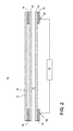
- the first support element 20 may further include a non-conductive bed 42 wherein the bed 42 may be positioned above the interdigitally arranged pluralities of teeth 28, 34 (not shown in FIG. 2 ).
- the bed 42 further includes a substantially smooth and flat upper surface 44 for receiving wet laundry.
- the bed 42 may be made of any suitable low loss, fire retardant materials that isolate the conductive elements from the articles to be dehydrated.
- the aforementioned structure of the laundry treating appliance 10 operates by creating a first capacitive coupling between the first cathode element 12 and the second cathode element 14 separated by at least a portion of the at least one support element 20, 23, a second capacitive coupling between the first anode element 16 and the second anode element 18 separated by at least a portion of the at least one support element 20, 23, and a third capacitive coupling between the pluralities of teeth 28, 34 of the second cathode element 14 and the second anode element 18, at least partially spaced from each other.
- wet laundry to be dried may be placed on the upper surface 44 of the bed 42.
- the RF applicator 22 may be continuously or intermittently energized to generate an e-field between the first, second, and third capacitive couplings which interacts with liquid in the laundry.
- the liquid residing within the e-field will be dielectrically heated to effect a drying of the laundry.
- one embodiment of the invention contemplates different geometric shapes for the laundry treating appliance 10, such as substantially longer, rectangular appliance 10 where the cathode and anode elements 12, 14, 16, 18 are elongated along the length of the appliance 10, or the longer appliance 10 includes a plurality of cathode and anode element 12, 14, 16, 18 sets.
- the upper surface 44 of the bed 42 may be smooth and slightly sloped to allow for the movement of wet laundry or water across the laundry treating appliance 10, wherein the one or more cathode and anode element 12, 14, 16, 18 sets may be energized individually or in combination by one or more RF applicators 22 to dry the laundry as it traverses the appliance 10.
- the bed 42 may be mechanically configured to move across the elongated laundry treating appliance 10 in a conveyor belt operation, wherein the one or more cathode and anode element 12, 14, 16, 18 sets may be energized individually or in combination by one or more RF applicators 22 to dry the laundry as it traverses the appliance 10.
- first cathode element 12, first anode element 16, or both elements 12, 16 may be positioned on the opposing side of the second support element 23, within the air gap 70.
- the air gap 70 may still separate the elements 12, 16 from the first support element 20, or the elements 12, 16 may be in communication with the first support element 20.
- FIG. 3 illustrates an alternative laundry treating appliance 110 according to a second embodiment of the invention.
- the second embodiment may be similar to the first embodiment; therefore, like parts will be identified with like numerals increased by 100, with it being understood that the description of the like parts of the first embodiment applies to the second embodiment, unless otherwise noted.
- a difference between the first embodiment and the second embodiment may be that laundry treating appliance 110 may be arranged in a drum-shaped configuration rotatable about a rotational axis 164, instead of the substantially flat configuration of the first embodiment.
- the support element includes a drum 119 having a nonconducting outer drum 121 having an outer surface 160 and an inner surface 162, and may further include a non-conductive element, such as a sleeve 142.
- the sleeve 142 further includes an inner surface 144 for receiving and supporting wet laundry.
- the inner surface 144 of the sleeve 142 may further include optional tumble elements 172, for example, baffles, to enable or prevent movement of laundry.
- the sleeve 142 and outer drum 121 may be made of any suitable low loss, fire retardant materials that isolate the conductive elements from the articles to be dehydrated. While a sleeve 142 is illustrated, other non-conductive elements are envisioned, such as one or more segments of non-conductive elements, or alternate geometric shapes of non-conductive elements.
- the conductive second cathode element 114, and the second anode elements 118 are similarly arranged in a drum configuration and fixedly mounted to the outer surface 143 of the sleeve 142.
- the opposing first and second comb elements 124, 130 include respective first and second bases 126, 132 encircling the rotational axis 164, and respective first and second pluralities of teeth 128, 134, interdigitally arranged about the rotational axis 164.
- the laundry treating appliance 110 further includes a conductive first cathode element comprising at least a partial cathode ring 112 encircling a first radial segment 166 of the drum 119 and an axially spaced opposing conductive first anode element comprising at least a partial anode ring 116 encircling a second radial segment 168 of the drum 119, which may be different from the first radial segment 166.
- a portion of the drum 119 separates the at least partially axially-aligned cathode ring 112 and the first base 126 portion of the second cathode elements 114.
- At least a portion of the drum 119 separates the at least partially axially-aligned anode ring 116 and the second base 132 portion of the second anode element 118. Additionally, this configuration aligns the first base 126 with the first radial segment 166, and the second base 132 with the second radial segment 168. Alternate configurations are envisioned where only at least a portion of the drum 119 separates the cathode or anode rings 112, 116 from their respective first and second bases 126, 132.
- the RF applicator 22 may be configured to generate a field of electromagnetic radiation (e-field) within the radio frequency spectrum between outputs electrodes and may be electrically coupled between the cathode ring 112 and the anode ring 116 by conductors 36 connected to at least one respective cathode and anode ring contact point 138, 140.
- e-field electromagnetic radiation
- Each of the conductive cathode and anode elements 112, 114, 116, 118 remain at least partially spaced from each other by a separating gap, or by non-conductive segments, such as by the outer drum 121.
- the outer drum 121 may be made of any suitable low loss, fire retardant materials, or at least one layer of insulating materials that isolates the conductive cathode and anode elements 112, 114, 116, 118.
- the drum 119 may also provide a rigid structure for the laundry treating appliance 110, or may be further supported by secondary structural elements, such as a frame or truss system.
- the assembled laundry treating appliance 110 creates a substantially radial integration between the sleeve 142, second cathode and anode elements 114, 118 (cathode element not shown), and drum 119 elements. It may be envisioned that additional layers may be interleaved between the illustrated elements. Additionally, while the cathode ring 112 and anode ring 116 are shown offset about the rotational axis for illustrative purposes, alternate placement of each ring 112, 116 may be envisioned.
- the second embodiment of the laundry treating appliance 110 operates by creating a first capacitive coupling between the cathode ring 112 and the second cathode element 114 separated by at least a portion of the drum 119, a second capacitive coupling between the anode ring 116 and the second anode element 118 separated by at least a portion of the drum 119, and a third capacitive coupling between the pluralities of teeth 128, 134 of the second cathode element 114 and the second anode element 118, at least partially spaced from each other.
- wet laundry to be dried may be placed on the inner surface 144 of the sleeve 142.
- the drum 119 may rotate about the rotational axis 164 at a speed at which the tumble elements 172 may enable, for example, a folding or sliding motion of the laundry articles.
- the RF applicator 22 may be off, or may be continuously or intermittently energized to generate an e-field between the first, second, and third capacitive couplings which interacts with liquid in the laundry.
- the liquid interacting with the e-field located within the inner surface 144 will be dielectrically heated to effect a drying of the laundry.
- the cathode and anode rings 112, 116 may encircle larger or smaller radial segments, or may completely encircle the drum 119 at first and second radial segments 166, 168, as opposed to just partially encircling the drum 119 at a first and second radial segments 166, 168.
- the first and second bases 126 and 132 and the first and second plurality of teeth 128, 134 may only partially encircle the drum 119 as opposed to completely encircling the drum 119.
- the pluralities of teeth 28, 34, 128, 134 may be supported by slotted depressions in the support element 20 or sleeve 142 matching the teeth 28, 34, 128, 134 for improved dielectric, heating, or manufacturing characteristics of the appliance.
- the second cathode and anode elements 114, 118 may only partially extend along the outer surface 143 of the sleeve 142.
- the RF applicator 22 may be intermittently energized to generate an e-field between the first, second, and third capacitive couplings, wherein the intermittent energizing may be related to the rotation of the drum 119, or may be timed to correspond with one of aligned capacitive couplings, tumbling of the laundry, or power requirements of the laundry treating appliance 110.
- the RF applicator 22 may be moving during the continuous or intermittent energizing of the e-field between the first, second, and third capacitive couplings. For instance, the RF applicator 22 may rotate about the rotational axis 164 at similar or dissimilar periods and directions as the drum 119.
- the drum may be rotationally stopped or rotationally slowed while the RF applicator 22 continuously or intermittently energizes to generate an e-field between the first, second, and third capacitive couplings.
- FIG. 5 illustrates an alternative assembled laundry treating appliance 210, according to the third embodiment of the invention.
- the third embodiment may be similar to the first and second embodiments; therefore, like parts will be identified with like numerals increased by 200, with it being understood that the description of the like parts of the first and second embodiment applies to the third embodiment, unless otherwise noted.
- a difference between the first embodiment and the second embodiment may be that laundry treating appliance 210 may be arranged in a drum-shaped configuration, wherein the outer drum 121 is separated from the second anode element 118 by a second drum element 223 and an air gap 270.
- anode ring 116 and cathode ring 112 are elongated about a larger radial segment of the drum 119.
- the cathode ring 112, anode ring 116, or both rings 112, 116 may be positioned on the opposing side of the outer drum 121, within the air gap 270.
- the air gap 270 may still separate the elements 112, 116 from the second drum element 223, or the elements 112, 116 may be in communication with the second drum element 223.
- the operation of the third embodiment is similar to that of the second embodiment.
- FIG. 6 illustrates an alternative laundry treating appliance 310 according to a fourth embodiment of the invention.
- the fourth embodiment may be similar to the second or third embodiments; therefore, like parts will be identified with like numerals beginning with 300, with it being understood that the description of the like parts of the first, second, and third embodiments apply to the fourth embodiment, unless otherwise noted.
- a difference between the prior embodiments and the fourth embodiment may be that first cathode and anode elements include cathode and anode rings 312, 316 assembled at axially opposite ends of the drum 319. This configuration may be placed within a housing, for instance, a household dryer cabinet (not shown).
- the assembled cathode and anode rings 312, 316 are electrically isolated by, for example, at least a portion of the drum 319 or air gap (not shown). In this sense, the laundry treating appliance 310 retains the first and second capacitive couplings of the second embodiment.
- the RF applicator 22 may be configured to generate a field of electromagnetic radiation (e-field) within the radio frequency spectrum between outputs electrodes and may be electrically coupled between the cathode ring 312 and the anode ring 316 by conductors 36 connected to at least one respective cathode and anode ring contact point 338, 340.
- the cathode and anode ring contact points 338, 340 may further include direct conductive coupling through additional components of the dryer cabinet supporting the rotating drum 319, such as via ball bearings (not shown). Other direct conductive coupling through additional components of the dryer cabinet may be envisioned.
- the fourth embodiment of the laundry treating appliance 310 operates by creating a first capacitive coupling between the cathode ring 312 and the second cathode element 114 separated by at least a portion of the drum 319 or air gap, a second capacitive coupling between the anode ring 316 and the second anode element 118 separated by at least a portion of the drum 319 or air gap.
- the RF applicator 22 may be off, or may be continuously or intermittently energized to generate an e-field between the first, second, and third capacitive couplings which interacts with liquid in the laundry.
- the liquid interacting with the e-field located within the inner surface 144 will be dielectrically heated to effect a drying of the laundry.
- FIG. 7 illustrates an embodiment where the appliance is a laundry treating appliance, such as a clothes dryer 410, incorporating the drum 119, 219, 319 (illustrated as drum 119), which defines a treating chamber 412 for receiving laundry for treatment, such as drying.
- the clothes dryer comprises an air system 414 supplying and exhausting air from the treating chamber, which includes a blower 416.
- a heating system 418 is provided for hybrid heating the air supplied by the air system 414, such that the heated air may be used in addition to the dielectric heating.
- the heating system 418 may work in cooperation with the laundry treating appliance 110, as described herein.
- first and second pluralities of teeth are envisioned wherein the interleaving of the teeth are designed to provide optimal electromagnetic coupling while keeping their physical size to a minimum.
- the spacing between the pluralities of teeth may be larger or smaller than illustrated.
- the embodiments disclosed herein provide a laundry treating appliance using RF applicator to dielectrically heat liquid in wet articles to effect a drying of the articles.
- One advantage that may be realized in the above embodiments may be that the above described embodiments are able to dry articles of clothing during rotational or stationary activity, allowing the most efficient e-field to be applied to the clothing for particular cycles or clothing characteristics.
- a further advantage of the above embodiments may be that the above embodiments allow for selective energizing of the RF applicator according to such additional design considerations as efficiency or power consumption during operation.
- the design of the anode and cathode may be controlled to allow for individual energizing of particular RF applicators in a single or multi-applicator embodiment.
- the effect of individual energizing of particular RF applicators results in avoiding anode/cathode pairs that would result in no additional material drying (if energized), reducing the unwanted impedance of additional anode/cathode pairs and electromagnetic fields inside the drum, and an overall reduction to energy costs of a drying cycle of operation due to increased efficiencies.
- reducing unwanted fields will help reduce undesirable coupling of energy into isolation materials between capacitive coupled regions.
- the capacitive couplings in embodiments of the invention allow the drying operations to move or rotate freely without the need for physical connections between the RF applicator and the pluralities of teeth. Due to the lack of physical connections, there will be fewer mechanical couplings to moving or rotating embodiments of the invention, and thus, an increased reliability appliance.
Landscapes
- Engineering & Computer Science (AREA)
- Microbiology (AREA)
- Life Sciences & Earth Sciences (AREA)
- Electromagnetism (AREA)
- Physics & Mathematics (AREA)
- Mechanical Engineering (AREA)
- General Engineering & Computer Science (AREA)
- Biotechnology (AREA)
- Biomedical Technology (AREA)
- Molecular Biology (AREA)
- Health & Medical Sciences (AREA)
- Textile Engineering (AREA)
- Drying Of Solid Materials (AREA)
- Accessory Of Washing/Drying Machine, Commercial Washing/Drying Machine, Other Washing/Drying Machine (AREA)
Abstract
Description
- This disclosure relates generally to laundry drying, and, more particularly, to methods and apparatus to dry laundry using radio frequency (RF) signals.
- Dielectric heating is the process in which a high-frequency alternating electric field heats a dielectric material, such as water molecules. At higher frequencies, this heating is caused by molecular dipole rotation within the dielectric material, while at lower frequencies in conductive fluids, other mechanisms such as ion-drag are more important in generating thermal energy.
- Microwave frequencies are typically applied for cooking food items and are considered undesirable for drying laundry articles because of the possible temporary runaway thermal effects random application of the waves in a traditional microwave. Radio frequencies and their corresponding controlled and contained e-field are typically used for drying of textile material.
- When applying an RF electronic field (e-field) to a wet article, such as a clothing material, the e-field may cause the water molecules within the e-field to dielectrically heat, generating thermal energy which effects the rapid drying of the articles.
- One aspect of the invention is directed to a method for drying an article with an RF applicator having a first anode element, a second anode element, a first cathode element, and a second cathode element, each second anode and cathode elements supported on a support element. The method includes capacitively coupling, through the support element, the first anode element to the second anode element, and the first cathode element to the second cathode element, capacitively coupling the second anode element to the second cathode element, and energizing the RF applicator to generate a field of electromagnetic radiation (e-field) within the radio frequency spectrum between the second anode and second cathode elements wherein liquid in the article residing within the e-field will be dielectrically heated to effect a drying of the article.
- In the drawings:
-
FIG. 1 is a schematic isometric view of the laundry treating apparatus in accordance with the first embodiment of the invention. -
FIG. 2 is a partial sectional view taken along line II-II ofFIG. 1 in accordance with the first embodiment of the invention. -
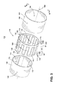
FIG. 3 is an exploded isometric view of an axially-exploded laundry treating apparatus with a rotating drum configuration, in accordance with the second embodiment of the invention. -
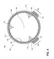
FIG. 4 is a partial sectional view taken along line IV-IV ofFIG. 3 showing the assembled configuration of the drum and anode/cathode elements, in accordance with the second embodiment of the invention. -
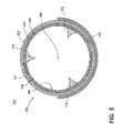
FIG. 5 is a partial sectional view showing an alternate assembled configuration of the drum and anode/cathode elements, in accordance with the third embodiment of the invention. -
FIG. 6 is an exploded isometric view of an axially-exploded laundry treating apparatus with a rotating drum configuration having integrated anode/cathode rings, in accordance with the fourth embodiment of the invention. -
FIG. 7 is a schematic isometric view of an embodiment where the laundry treating appliance is shown as a clothes dryer incorporating the drum of the second, third, and fourth embodiments. - While this description may be primarily directed toward a laundry drying machine, the invention may be applicable in any environment using an RF signal application to dehydrate any wet article.
-
FIG. 1 is a schematic illustration of alaundry treating appliance 10 according to the first embodiment of the invention for dehydrating one or more articles, such as articles of clothing. As illustrated inFIG. 1 , thelaundry treating appliance 10 has a structure that includes conductive elements, such as afirst cathode element 12 and asecond cathode element 14, and an opposingfirst anode element 16, asecond anode element 18, in addition to a first non-conductivelaundry support element 20, an optional secondnon-conductive support element 23, and anRF applicator 22. - The
second cathode element 14 further includes afirst comb element 24 having afirst base 26 from which extend a first plurality ofteeth 28, and thesecond anode element 18 includes asecond comb element 30 having asecond base 32 from which extend a second plurality ofteeth 34. The second cathode andsecond anode elements element 20 in such a way as to interdigitally arrange the first and second pluralities ofteeth second anode elements first support element 20 by, for example, adhesion, fastener connections, or laminated layers. Additionally, the first cathode andanode elements second support element 23 by similar mountings. Alternative mounting techniques may be employed. - At least a portion of either the first or
second support elements second cathode elements first cathode element 12 aligns with the substantially rectangularfirst base 26 portion of thesecond cathode element 14, through thefirst support element 20 andsecond support element 23, with thesupport elements optional air gap 70. Similarly shown, the elongatedfirst anode element 16 at least partially aligns with the substantially rectangularsecond base 32 portion of thesecond anode element 18 through a portion of thefirst support element 20 andsecond support element 23, with thesupport elements air gap 70. The aligned portions of the first andsecond cathode elements elements second anode elements - The
RF applicator 22 may be configured to generate a field of electromagnetic radiation (e-field) within the radio frequency spectrum between outputs electrodes and may be electrically coupled between thefirst cathode element 12 and thefirst anode element 16 byconductors 36 connected to at least one respective first anode andcathode contact point RF applicator 22 may be 13.56 million cycles per second (MHz). The generation of another RF signal, or varying RF signals, is envisioned. - Microwave frequencies are typically applied for cooking food items. However, their high frequency and resulting greater dielectric heating effect make microwave frequencies undesirable for drying laundry articles. Radio frequencies and their corresponding lower dielectric heating effect are typically used for drying of laundry. In contrast with a conventional microwave heating appliance, where microwaves generated by a magnetron are directed into a resonant cavity by a waveguide, the
RF applicator 22 induces a controlled electromagnetic field between the cathode andanode elements RF applicator 22 is a wave pool. It is understood that the differences between microwave ovens and RF dryers arise from the differences between the implementation structures of applicator vs. magnetron/waveguide, which renders much of the microwave solutions inapplicable for RF dryers. - Each of the conductive cathode and
anode elements second support elements optional air gap 70. Thesupport elements anode elements support elements laundry treating appliance 10, or may be further supported by secondary structural elements, such as a frame or truss system. Theair gap 70 may provide enough separation to prevent arcing or other unintentional conduction, based on the electrical characteristics of thelaundry treating apparatus 10. - Turning now to the partial sectional view of
FIG. 2 , taken along line II-II ofFIG. 1 in accordance with the first embodiment of the invention, thefirst support element 20 may further include anon-conductive bed 42 wherein thebed 42 may be positioned above the interdigitally arranged pluralities ofteeth 28, 34 (not shown inFIG. 2 ). Thebed 42 further includes a substantially smooth and flatupper surface 44 for receiving wet laundry. Thebed 42 may be made of any suitable low loss, fire retardant materials that isolate the conductive elements from the articles to be dehydrated. - The aforementioned structure of the
laundry treating appliance 10 operates by creating a first capacitive coupling between thefirst cathode element 12 and thesecond cathode element 14 separated by at least a portion of the at least onesupport element first anode element 16 and thesecond anode element 18 separated by at least a portion of the at least onesupport element teeth second cathode element 14 and thesecond anode element 18, at least partially spaced from each other. During drying operations, wet laundry to be dried may be placed on theupper surface 44 of thebed 42. During, for instance, a predetermined cycle of operation, theRF applicator 22 may be continuously or intermittently energized to generate an e-field between the first, second, and third capacitive couplings which interacts with liquid in the laundry. The liquid residing within the e-field will be dielectrically heated to effect a drying of the laundry. - Many other possible configurations in addition to that shown in the above figures are contemplated by the present embodiment. For example, one embodiment of the invention contemplates different geometric shapes for the
laundry treating appliance 10, such as substantially longer,rectangular appliance 10 where the cathode andanode elements appliance 10, or thelonger appliance 10 includes a plurality of cathode andanode element upper surface 44 of thebed 42 may be smooth and slightly sloped to allow for the movement of wet laundry or water across thelaundry treating appliance 10, wherein the one or more cathode andanode element more RF applicators 22 to dry the laundry as it traverses theappliance 10. Alternatively, thebed 42 may be mechanically configured to move across the elongatedlaundry treating appliance 10 in a conveyor belt operation, wherein the one or more cathode andanode element more RF applicators 22 to dry the laundry as it traverses theappliance 10. - Additionally, a configuration is envisioned wherein only a
single support element 20 separates the first cathode andanode elements anode elements optional air gap 70. In another embodiment, thefirst cathode element 12,first anode element 16, or bothelements second support element 23, within theair gap 70. In this embodiment, theair gap 70 may still separate theelements first support element 20, or theelements first support element 20. - Furthermore,
FIG. 3 illustrates an alternativelaundry treating appliance 110 according to a second embodiment of the invention. The second embodiment may be similar to the first embodiment; therefore, like parts will be identified with like numerals increased by 100, with it being understood that the description of the like parts of the first embodiment applies to the second embodiment, unless otherwise noted. A difference between the first embodiment and the second embodiment may be thatlaundry treating appliance 110 may be arranged in a drum-shaped configuration rotatable about arotational axis 164, instead of the substantially flat configuration of the first embodiment. - In this embodiment, the support element includes a
drum 119 having a nonconductingouter drum 121 having anouter surface 160 and aninner surface 162, and may further include a non-conductive element, such as asleeve 142. Thesleeve 142 further includes aninner surface 144 for receiving and supporting wet laundry. Theinner surface 144 of thesleeve 142 may further includeoptional tumble elements 172, for example, baffles, to enable or prevent movement of laundry. Thesleeve 142 andouter drum 121 may be made of any suitable low loss, fire retardant materials that isolate the conductive elements from the articles to be dehydrated. While asleeve 142 is illustrated, other non-conductive elements are envisioned, such as one or more segments of non-conductive elements, or alternate geometric shapes of non-conductive elements. - As illustrated, the conductive
second cathode element 114, and thesecond anode elements 118 are similarly arranged in a drum configuration and fixedly mounted to theouter surface 143 of thesleeve 142. In this embodiment, the opposing first andsecond comb elements second bases rotational axis 164, and respective first and second pluralities ofteeth rotational axis 164. - The
laundry treating appliance 110 further includes a conductive first cathode element comprising at least apartial cathode ring 112 encircling a firstradial segment 166 of thedrum 119 and an axially spaced opposing conductive first anode element comprising at least apartial anode ring 116 encircling a secondradial segment 168 of thedrum 119, which may be different from the firstradial segment 166. As shown, at least a portion of thedrum 119 separates the at least partially axially-alignedcathode ring 112 and thefirst base 126 portion of thesecond cathode elements 114. Similarly, at least a portion of thedrum 119 separates the at least partially axially-alignedanode ring 116 and thesecond base 132 portion of thesecond anode element 118. Additionally, this configuration aligns thefirst base 126 with the firstradial segment 166, and thesecond base 132 with the secondradial segment 168. Alternate configurations are envisioned where only at least a portion of thedrum 119 separates the cathode or anode rings 112, 116 from their respective first andsecond bases - The
RF applicator 22 may be configured to generate a field of electromagnetic radiation (e-field) within the radio frequency spectrum between outputs electrodes and may be electrically coupled between thecathode ring 112 and theanode ring 116 byconductors 36 connected to at least one respective cathode and anodering contact point - Each of the conductive cathode and
anode elements outer drum 121. Theouter drum 121 may be made of any suitable low loss, fire retardant materials, or at least one layer of insulating materials that isolates the conductive cathode andanode elements drum 119 may also provide a rigid structure for thelaundry treating appliance 110, or may be further supported by secondary structural elements, such as a frame or truss system. - As shown in
FIG. 4 , the assembledlaundry treating appliance 110, according to the second embodiment of the invention, creates a substantially radial integration between thesleeve 142, second cathode andanode elements 114, 118 (cathode element not shown), and drum 119 elements. It may be envisioned that additional layers may be interleaved between the illustrated elements. Additionally, while thecathode ring 112 andanode ring 116 are shown offset about the rotational axis for illustrative purposes, alternate placement of eachring - The second embodiment of the
laundry treating appliance 110 operates by creating a first capacitive coupling between thecathode ring 112 and thesecond cathode element 114 separated by at least a portion of thedrum 119, a second capacitive coupling between theanode ring 116 and thesecond anode element 118 separated by at least a portion of thedrum 119, and a third capacitive coupling between the pluralities ofteeth second cathode element 114 and thesecond anode element 118, at least partially spaced from each other. - During drying operations, wet laundry to be dried may be placed on the
inner surface 144 of thesleeve 142. During a cycle of operation, thedrum 119 may rotate about therotational axis 164 at a speed at which thetumble elements 172 may enable, for example, a folding or sliding motion of the laundry articles. During rotation, theRF applicator 22 may be off, or may be continuously or intermittently energized to generate an e-field between the first, second, and third capacitive couplings which interacts with liquid in the laundry. The liquid interacting with the e-field located within theinner surface 144 will be dielectrically heated to effect a drying of the laundry. - Many other possible configurations in addition to that shown in the above figures are contemplated by the present embodiment. For example, in another configuration, the cathode and anode rings 112, 116 may encircle larger or smaller radial segments, or may completely encircle the
drum 119 at first and secondradial segments drum 119 at a first and secondradial segments second bases teeth drum 119 as opposed to completely encircling thedrum 119. In even another configuration, the pluralities ofteeth support element 20 orsleeve 142 matching theteeth anode elements outer surface 143 of thesleeve 142. - In an alternate operation of the second embodiment, the
RF applicator 22 may be intermittently energized to generate an e-field between the first, second, and third capacitive couplings, wherein the intermittent energizing may be related to the rotation of thedrum 119, or may be timed to correspond with one of aligned capacitive couplings, tumbling of the laundry, or power requirements of thelaundry treating appliance 110. In another alternate operation of the second embodiment, theRF applicator 22 may be moving during the continuous or intermittent energizing of the e-field between the first, second, and third capacitive couplings. For instance, theRF applicator 22 may rotate about therotational axis 164 at similar or dissimilar periods and directions as thedrum 119. In yet another alternate operation of the second embodiment, the drum may be rotationally stopped or rotationally slowed while theRF applicator 22 continuously or intermittently energizes to generate an e-field between the first, second, and third capacitive couplings. -
FIG. 5 illustrates an alternative assembledlaundry treating appliance 210, according to the third embodiment of the invention. The third embodiment may be similar to the first and second embodiments; therefore, like parts will be identified with like numerals increased by 200, with it being understood that the description of the like parts of the first and second embodiment applies to the third embodiment, unless otherwise noted. A difference between the first embodiment and the second embodiment may be thatlaundry treating appliance 210 may be arranged in a drum-shaped configuration, wherein theouter drum 121 is separated from thesecond anode element 118 by asecond drum element 223 and anair gap 270. - Additionally, the
same anode ring 116 and cathode ring 112 (not shown) are elongated about a larger radial segment of thedrum 119. Alternatively, thecathode ring 112,anode ring 116, or bothrings outer drum 121, within theair gap 270. In this embodiment, theair gap 270 may still separate theelements second drum element 223, or theelements second drum element 223. The operation of the third embodiment is similar to that of the second embodiment. -
FIG. 6 illustrates an alternativelaundry treating appliance 310 according to a fourth embodiment of the invention. The fourth embodiment may be similar to the second or third embodiments; therefore, like parts will be identified with like numerals beginning with 300, with it being understood that the description of the like parts of the first, second, and third embodiments apply to the fourth embodiment, unless otherwise noted. A difference between the prior embodiments and the fourth embodiment may be that first cathode and anode elements include cathode and anode rings 312, 316 assembled at axially opposite ends of thedrum 319. This configuration may be placed within a housing, for instance, a household dryer cabinet (not shown). - In this embodiment, the assembled cathode and anode rings 312, 316 are electrically isolated by, for example, at least a portion of the
drum 319 or air gap (not shown). In this sense, thelaundry treating appliance 310 retains the first and second capacitive couplings of the second embodiment. - The
RF applicator 22 may be configured to generate a field of electromagnetic radiation (e-field) within the radio frequency spectrum between outputs electrodes and may be electrically coupled between thecathode ring 312 and theanode ring 316 byconductors 36 connected to at least one respective cathode and anodering contact point rotating drum 319, such as via ball bearings (not shown). Other direct conductive coupling through additional components of the dryer cabinet may be envisioned. - The fourth embodiment of the
laundry treating appliance 310 operates by creating a first capacitive coupling between thecathode ring 312 and thesecond cathode element 114 separated by at least a portion of thedrum 319 or air gap, a second capacitive coupling between theanode ring 316 and thesecond anode element 118 separated by at least a portion of thedrum 319 or air gap. During rotation, theRF applicator 22 may be off, or may be continuously or intermittently energized to generate an e-field between the first, second, and third capacitive couplings which interacts with liquid in the laundry. The liquid interacting with the e-field located within theinner surface 144 will be dielectrically heated to effect a drying of the laundry. -
FIG. 7 illustrates an embodiment where the appliance is a laundry treating appliance, such as aclothes dryer 410, incorporating thedrum 119, 219, 319 (illustrated as drum 119), which defines a treatingchamber 412 for receiving laundry for treatment, such as drying. The clothes dryer comprises anair system 414 supplying and exhausting air from the treating chamber, which includes ablower 416. Aheating system 418 is provided for hybrid heating the air supplied by theair system 414, such that the heated air may be used in addition to the dielectric heating. Theheating system 418 may work in cooperation with thelaundry treating appliance 110, as described herein. - Many other possible embodiments and configurations in addition to those shown in the above figures are contemplated by the present disclosure. For example, alternate geometric configurations of the first and second pluralities of teeth are envisioned wherein the interleaving of the teeth are designed to provide optimal electromagnetic coupling while keeping their physical size to a minimum. Additionally, the spacing between the pluralities of teeth may be larger or smaller than illustrated.
- The embodiments disclosed herein provide a laundry treating appliance using RF applicator to dielectrically heat liquid in wet articles to effect a drying of the articles. One advantage that may be realized in the above embodiments may be that the above described embodiments are able to dry articles of clothing during rotational or stationary activity, allowing the most efficient e-field to be applied to the clothing for particular cycles or clothing characteristics. A further advantage of the above embodiments may be that the above embodiments allow for selective energizing of the RF applicator according to such additional design considerations as efficiency or power consumption during operation.
- Additionally, the design of the anode and cathode may be controlled to allow for individual energizing of particular RF applicators in a single or multi-applicator embodiment. The effect of individual energizing of particular RF applicators results in avoiding anode/cathode pairs that would result in no additional material drying (if energized), reducing the unwanted impedance of additional anode/cathode pairs and electromagnetic fields inside the drum, and an overall reduction to energy costs of a drying cycle of operation due to increased efficiencies. Finally, reducing unwanted fields will help reduce undesirable coupling of energy into isolation materials between capacitive coupled regions.
- Moreover, the capacitive couplings in embodiments of the invention allow the drying operations to move or rotate freely without the need for physical connections between the RF applicator and the pluralities of teeth. Due to the lack of physical connections, there will be fewer mechanical couplings to moving or rotating embodiments of the invention, and thus, an increased reliability appliance.
- This written description uses examples to disclose the invention, including the best mode, and also to enable any person skilled in the art to practice the invention, including making and using any devices or systems and performing any incorporated methods.
Claims (15)
- A method to dry an article with a radio frequency (RF) applicator (22) having a first anode element (16), a second anode element (18), a first cathode element (12), and a second cathode element (14), each second anode and cathode elements (18, 14) supported on a support element (20), the method comprising:capacitively couple, through the support element (20), the first anode element (16) to the second anode element (18), and the first cathode element (12) to the second cathode element (14);capacitively couple the second anode element (18) to the second cathode element (14); andenergize the RF applicator (22) to generate a field of electromagnetic radiation (e-field) within a radio frequency spectrum between the second anode element (18) and the second cathode element (14);wherein liquid in the article residing within the e-field will be dielectrically heated to effect a drying of the article.
- A method according to claim 1, further comprising moving the RF applicator (22) during the energizing of the RF applicator (22).
- A method according to claim 2, wherein the support element (20) is in the shape of a drum (119) and the moving the RF applicator (22) comprises rotation of the drum (119).
- A method according to claim 3, wherein the e-field is located above at least a portion of an inner surface (162) of the drum (119) and the article is supported on the inner surface (162) of the drum (119).
- A method according to claim 4, wherein the energizing of the RF applicator (22) comprises intermittently energizing of the RF applicator (22).
- A method according to claim 5, wherein the rotation of the drum (119) is related to the intermittent energizing of the RF applicator (22).
- A method according to claim 4 or 5, wherein the capacitively couple comprises capacitive couple between the first and second anode elements (16, 18) at a first radial segment (166) of the drum (119) and capacitive couple between the first and second cathode elements (12, 14) at a second radial segment (168) of the drum (119), axially spaced from the first radial segment (166).
- A method according to claim 7, wherein the capacitively couple comprises capacitive couple through a first conductive ring (112) encircling the drum (119) about the first radial segment (166) and a second ring (116) encircling the drum (119) about the second radial segment (168).
- An article treatment appliance to dry an article according to a predetermined cycle of operation, comprising:a support element (20);a first anode element (16) and a first cathode element (12);a second anode element (18) and a second cathode element (14) operably supported by the support element (20);the first anode element (16) capacitively coupled with the second anode element (18) and operably separated by at least a portion of the support element (20);the first cathode element (12) capacitively coupled with the second cathode element (14) and operably separated by at least a portion of the support element (20);the second anode element (18) capacitively coupled with the second cathode element (14) and operably spaced from each other; anda radio frequency (RF) applicator (22) coupled with the first anode element (16) and the first cathode element (12) and operable to selectively energize to generate electromagnetic radiation in a radio frequency spectrum;wherein the energizing of the RF applicator (22) sends electromagnetic radiation through the applicator (22) via the capacitive couples to form a field of electromagnetic radiation, e-field, in the radio frequency spectrum, operable to dielectrically heat liquid within the article on the support element (20).
- An article treatment appliance according to claim 9, wherein the support element (20) comprises a bed (42), with the article supported on an upper surface (44) of the bed (42).
- An article treatment appliance according to claim 9 or 10, wherein the support element (20) comprises a drum (119), the first anode element (16) comprises an anode ring (116) encircling a first radial segment (168) of the drum (119), and the first cathode element (12) comprises a cathode ring (112) encircling a second radial segment (166) of the drum (119), which is different from the first radial segment (168).
- An article treatment appliance according to claim 11, wherein the first and second radial segments (166, 168) are axially spaced from each other.
- An article treatment appliance according to claim 11, wherein the second anode element (18) comprises a first comb element (24) having a first base (26) from which extend a first plurality of teeth (28), the second cathode element (14) comprises a second comb element (30) having a second base (32) from which extend a second plurality of teeth (34), with first and second plurality of teeth (28, 34) are interdigitally arranged, and the first base (26) is axially aligned with the first radial segment (168) and the second base (32) is axially aligned with the second radial segment (166).
- An article treatment appliance according to any of claims 9 to 13, wherein at least one of the second anode element (18) and the second cathode element (14) are encapsulated within the support element (20).
- An article treatment appliance according to any of claims 9 to 14, wherein the second anode element (18) comprises a first comb element (24) having a first base (26) from which extend a first plurality of teeth (28), the second cathode element (14) comprises a second comb element (30) having a second base (32) from which extend a second plurality of teeth (34), wherein the first and second plurality of teeth (28, 34) are interdigitally arranged.
Priority Applications (1)
| Application Number | Priority Date | Filing Date | Title |
|---|---|---|---|
| PL14175081T PL2827087T3 (en) | 2013-07-17 | 2014-06-30 | Method for drying articles |
Applications Claiming Priority (1)
| Application Number | Priority Date | Filing Date | Title |
|---|---|---|---|
| US13/943,918 US9541330B2 (en) | 2013-07-17 | 2013-07-17 | Method for drying articles |
Publications (2)
| Publication Number | Publication Date |
|---|---|
| EP2827087A1 true EP2827087A1 (en) | 2015-01-21 |
| EP2827087B1 EP2827087B1 (en) | 2016-12-28 |
Family
ID=51210997
Family Applications (1)
| Application Number | Title | Priority Date | Filing Date |
|---|---|---|---|
| EP14175081.0A Not-in-force EP2827087B1 (en) | 2013-07-17 | 2014-06-30 | Method for drying articles |
Country Status (3)
| Country | Link |
|---|---|
| US (4) | US9541330B2 (en) |
| EP (1) | EP2827087B1 (en) |
| PL (1) | PL2827087T3 (en) |
Cited By (8)
| Publication number | Priority date | Publication date | Assignee | Title |
|---|---|---|---|---|
| EP2849533A1 (en) * | 2013-08-14 | 2015-03-18 | Whirlpool Corporation | Appliance for drying articles |
| WO2016182832A1 (en) * | 2015-05-08 | 2016-11-17 | Ut-Battelle, Llc | Dryer using high frequency vibration |
| US10006163B2 (en) | 2015-03-23 | 2018-06-26 | Whirlpool Corporation | Apparatus for drying articles |
| US10024899B2 (en) | 2013-10-16 | 2018-07-17 | Whirlpool Corporation | Method and apparatus for detecting an energized e-field |
| US10184718B2 (en) | 2013-07-17 | 2019-01-22 | Whirlpool Corporation | Method for drying articles |
| US10246813B2 (en) | 2013-12-09 | 2019-04-02 | Whirlpool Corporation | Method for drying articles |
| US10323881B2 (en) | 2013-10-02 | 2019-06-18 | Whirlpool Corporation | Method and apparatus for drying articles |
| US10837702B2 (en) | 2013-08-23 | 2020-11-17 | Whirlpool Corporation | Appliance for drying articles |
Families Citing this family (5)
| Publication number | Priority date | Publication date | Assignee | Title |
|---|---|---|---|---|
| US9200402B2 (en) | 2011-05-20 | 2015-12-01 | Cool Dry, Inc. | Dielectric dryer drum |
| US9194625B2 (en) * | 2013-08-20 | 2015-11-24 | Whirlpool Corporation | Method for drying articles |
| US9447537B2 (en) | 2014-11-12 | 2016-09-20 | Cool Dry, Inc. | Fixed radial anode drum dryer |
| US10487443B1 (en) | 2015-10-30 | 2019-11-26 | Cool Dry, Inc. | Hybrid RF/conventional clothes dryer |
| WO2022050825A1 (en) * | 2020-09-07 | 2022-03-10 | Lg Electronics Inc. | Laundry drying machine and controlling method of laundry drying machine |
Citations (3)
| Publication number | Priority date | Publication date | Assignee | Title |
|---|---|---|---|---|
| US1503224A (en) * | 1921-03-28 | 1924-07-29 | Miehle Printing Press & Mfg | Portable antioffset device |
| US4296298A (en) * | 1978-06-12 | 1981-10-20 | Raytheon Company | Dielectric cooking apparatus |
| US20120291304A1 (en) * | 2011-05-20 | 2012-11-22 | Cool Dry LLC | Dielectric dryer drum |
Family Cites Families (144)
| Publication number | Priority date | Publication date | Assignee | Title |
|---|---|---|---|---|
| US2511839A (en) * | 1950-06-20 | Method and apparatus for drying | ||
| GB601855A (en) | 1945-10-09 | 1948-05-13 | Dennis Illingworth Lawson | Applicator for radio frequency dielectric heating |
| US1871269A (en) | 1929-09-25 | 1932-08-09 | Western Electric Co | Method of drying materials |
| US2112418A (en) | 1935-12-31 | 1938-03-29 | United Shoe Machinery Corp | Electrical drying |
| US2231457A (en) | 1936-08-03 | 1941-02-11 | John L Stephen | Electrical apparatus |
| GB501855A (en) | 1936-11-16 | 1939-03-07 | Chem Ind Basel | Manufacture of azo-dyestuffs |
| US2212522A (en) | 1937-12-17 | 1940-08-27 | United Shoe Machinery Corp | Use of a stray electrostatic field for drying leather and the like |
| US2226871A (en) | 1938-04-09 | 1940-12-31 | Hall Printing Co W F | Apparatus for drying |
| US2228136A (en) | 1940-03-01 | 1941-01-07 | United Shoe Machinery Corp | Sole attaching utilizing stray electrostatic field |
| US2276996A (en) | 1940-11-30 | 1942-03-17 | A J Ginsberg | Non-radio-interfering therapeutic apparatus |
| FR954490A (en) | 1941-12-27 | 1950-01-03 | ||
| US2449317A (en) | 1944-04-18 | 1948-09-14 | Compo Shoe Machinery Corp | Electrostatic pressing apparatus |
| US2642000A (en) | 1944-11-29 | 1953-06-16 | Hoe & Co R | Ink drying equipment for web printing machines |
| US2492187A (en) | 1945-01-05 | 1949-12-27 | Ralph A Rusca | Method and apparatus for electrical heating |
| US2473251A (en) | 1945-05-29 | 1949-06-14 | Gen Electric | High-frequency dielectric heating apparatus |
| US2464403A (en) | 1945-08-30 | 1949-03-15 | Rca Corp | Apparatus for heating dielectric materials electronically |
| US2542589A (en) | 1946-05-16 | 1951-02-20 | Induction Heating Corp | Electrode structure and method for dielectric heating |
| US2512311A (en) | 1948-09-01 | 1950-06-20 | Gen Electric | High-frequency heating apparatus |
| US2656839A (en) | 1950-02-14 | 1953-10-27 | Clarence B Howard | Electrotherapeutic oscillator |
| US2740756A (en) | 1951-04-19 | 1956-04-03 | Albert G Thomas | Electrical drying system |
| US3089327A (en) | 1951-09-07 | 1963-05-14 | Murray Corp | Apparatus for the complete laundering of fabrics |
| US2773162A (en) | 1954-01-14 | 1956-12-04 | Boeing Co | Anti-icing of windows by dielectric heating |
| GB964180A (en) | 1960-09-12 | 1964-07-15 | Svenska Sockerfabriks Ab | Improvements in or relating to dielectrically heated drying apparatuses through which the articles to be dried are continuously advanced |
| US3184637A (en) | 1961-12-13 | 1965-05-18 | Decca Ltd | Lamp monitoring apparatus |
| US3316380A (en) | 1964-04-30 | 1967-04-25 | Gen Motors Corp | Energy distribution detector for microwave oven |
| US3355812A (en) | 1965-08-04 | 1967-12-05 | Fitchburg Paper | Drying by high frequency electric field |
| US3329796A (en) | 1966-07-28 | 1967-07-04 | Radio Frequency Company Inc | Radio frequency apparatus |
| US3426439A (en) | 1967-02-16 | 1969-02-11 | Houston Fearless Corp | Microwave drying system |
| US3404466A (en) | 1967-06-28 | 1968-10-08 | Gen Electric | Electronic dryer control |
| US3439431A (en) | 1967-12-15 | 1969-04-22 | Gen Electric | Microwave dryer control circuit |
| US3543408A (en) | 1968-10-21 | 1970-12-01 | Robert R Candor | Liquid removing apparatus and method |
| US3537185A (en) | 1968-10-21 | 1970-11-03 | Ingram Plywoods Inc | Dielectric heating apparatus |
| US3599342A (en) | 1969-03-03 | 1971-08-17 | Maytag Co | Dryer control |
| CA898902A (en) | 1969-06-30 | 1972-04-25 | C. Clark James | H.f. heating apparatus |
| US3601571A (en) | 1969-11-12 | 1971-08-24 | Park Ohio Industries Inc | Induction heating device with a controlled feeding mechanism |
| GB1255292A (en) | 1970-02-04 | 1971-12-01 | Marconi Co Ltd | Improvements in or relating to piezoelectric transducers |
| US3652816A (en) | 1970-04-13 | 1972-03-28 | Litton Business Systems Inc | Self cleaning dielectric heater |
| US3754336A (en) | 1971-08-10 | 1973-08-28 | E Feild | Vehicle drying apparatus |
| GB1370373A (en) | 1971-10-25 | 1974-10-16 | Electricity Council Hodgett D | Drying of textile fibres |
| US4014732A (en) | 1974-06-01 | 1977-03-29 | Firma Mohndruck, Reinhard Mohn Ohg | Device for drying and setting the adhesive on backs of books |
| LU70345A1 (en) | 1974-06-18 | 1976-05-31 | ||
| US3953701A (en) | 1975-03-24 | 1976-04-27 | Radio Frequency Co., Inc. | Radio frequency heating and ventilating electrode system |
| US4119826A (en) | 1977-04-04 | 1978-10-10 | Champion International Corporation | Dielectric heat generator |
| US4197851A (en) | 1977-04-14 | 1980-04-15 | Fellus Victor M | Apparatus for emitting high-frequency electromagnetic waves |
| DE2817067A1 (en) | 1978-04-19 | 1979-10-25 | Siemens Ag | CAPACITIVE HIGH FREQUENCY OVEN FOR DRYING FOLDED FIBER CABLES, IN PARTICULAR CHEMICAL FIBER CABLES |
| US4334136A (en) | 1979-10-01 | 1982-06-08 | Douglas P. Mahan | Microwave treating mechanism |
| US4296299A (en) | 1979-12-31 | 1981-10-20 | General Electric Company | Apparatus for thawing frozen food in a refrigeration appliance |
| US4365622A (en) | 1980-09-11 | 1982-12-28 | Donald L. Morton & Associates | Multiple plate resonant electrode |
| US4409541A (en) | 1981-03-19 | 1983-10-11 | Ppg Industries, Inc. | Method of and apparatus for determining continuity of an electrical conductor |
| US4471537A (en) | 1982-01-18 | 1984-09-18 | Indesit Industria Elettrodomestici Italiana S.P.A. | Dryer apparatus having an improved air circulation |
| US4529855A (en) | 1982-04-12 | 1985-07-16 | Henry Fleck | Microwave radiation detector |
| US4499818A (en) | 1982-09-30 | 1985-02-19 | Restaurant Technology, Inc. | Method and apparatus for holding freshly prepared fried food products |
| DE3343236A1 (en) | 1983-11-30 | 1985-06-05 | Hans 4600 Dortmund Baltes | METHOD AND DEVICE FOR DRYING AND STERILIZING TISSUE, IN PARTICULAR SENSITIVE TISSUE |
| US4523387A (en) | 1983-12-08 | 1985-06-18 | Mahan Douglas P | Microwave treating mechanism |
| JPS61151289U (en) | 1985-03-12 | 1986-09-18 | ||
| US4918290A (en) | 1985-10-28 | 1990-04-17 | Demars Robert A | Portable towel heating device |
| US4638571A (en) | 1986-04-02 | 1987-01-27 | Cook William A | Radio frequency nozzle bar dryer |
| GB8628138D0 (en) | 1986-11-25 | 1986-12-31 | Greenbank Eng Co Ltd | Suction drying apparatus |
| DE3819514A1 (en) | 1988-06-08 | 1989-12-14 | Passat Maschinenbau Gmbh | CONTROL SYSTEM WITH VALVE VALVES FOR A DRYER |
| US4845329A (en) | 1988-11-21 | 1989-07-04 | General Motors Corporation | Moisture removal from visual glass surfaces by dielectric heating |
| US5064979A (en) | 1990-08-07 | 1991-11-12 | W. R. Grace & Co.-Conn. | Microwave air float bar for drying a traveling web |
| US5197202A (en) | 1990-09-26 | 1993-03-30 | Ppg Industries, Inc. | Method and apparatus for drying and curing a coated strand |
| JPH04307095A (en) | 1991-04-03 | 1992-10-29 | Matsushita Electric Ind Co Ltd | Drying apparatus |
| DE4118433C2 (en) | 1991-06-05 | 1994-12-01 | Herbert Huettlin | Fluid bed apparatus for treating particulate goods |
| US5152075A (en) | 1991-09-27 | 1992-10-06 | Bonar George D | Drying of clothes by electrolysis |
| US5303484A (en) | 1992-04-09 | 1994-04-19 | Thermo Electron Web Systems, Inc. | Compact convective web dryer |
| US5593713A (en) | 1993-10-12 | 1997-01-14 | De La Luz-Martinez; Jose | Method for cooking tortillas using very low and low frequency radio waves |
| US5495250A (en) | 1993-11-01 | 1996-02-27 | Motorola, Inc. | Battery-powered RF tags and apparatus for manufacturing the same |
| US5394619A (en) | 1994-03-14 | 1995-03-07 | Kaplan; Bruce E. | Portable clothes dryer and room humidifier |
| IT1275556B (en) | 1995-07-14 | 1997-08-07 | Manzolli Daniela | PROCESS AND PLANT FOR THE DEHYDRATION OF FORAGE, IN PARTICULARLY FOR THE DEHYDRATION OF THE MEDICAL GRASS |
| US5659972A (en) | 1995-10-06 | 1997-08-26 | Avery Dennison Corporation | Apparatus and method for drying or curing web materials and coatings |
| US6546109B1 (en) | 2000-01-03 | 2003-04-08 | Louis Thomas Gnecco | Electromagnetically shielded hearing aids |
| USRE43519E1 (en) | 1995-11-13 | 2012-07-17 | Acacia Patent Acquisition Corporation | Electromagnetically protected hearing aids |
| US5838111A (en) | 1996-02-27 | 1998-11-17 | Matsushita Electric Industrial Co., Ltd. | Plasma generator with antennas attached to top electrodes |
| US5853579A (en) | 1996-11-26 | 1998-12-29 | Wastech International Inc. | Treatment system |
| US5819431A (en) | 1997-01-10 | 1998-10-13 | Lancer; Harold | Foot dryer apparatus and method of drying feet |
| US5877090A (en) | 1997-06-03 | 1999-03-02 | Applied Materials, Inc. | Selective plasma etching of silicon nitride in presence of silicon or silicon oxides using mixture of NH3 or SF6 and HBR and N2 |
| US5886081A (en) | 1997-08-05 | 1999-03-23 | Rockwell Science Center, Inc. | Efficient dielectrically heatable compound and method |
| JP3102637B2 (en) | 1997-10-08 | 2000-10-23 | エルジー電子株式会社 | Microwave washer / dryer |
| US20050120715A1 (en) | 1997-12-23 | 2005-06-09 | Christion School Of Technology Charitable Foundation Trust | Heat energy recapture and recycle and its new applications |
| US6303166B1 (en) | 1998-04-21 | 2001-10-16 | The State Of Oregon Acting By And Through The State Board Of Higher Education On Behalf Of Oregon State University | Capacative dielectric heating system |
| US6657173B2 (en) | 1998-04-21 | 2003-12-02 | State Board Of Higher Education On Behalf Of Oregon State University | Variable frequency automated capacitive radio frequency (RF) dielectric heating system |
| US7883609B2 (en) * | 1998-06-15 | 2011-02-08 | The Trustees Of Dartmouth College | Ice modification removal and prevention |
| DE19904147C2 (en) | 1999-02-03 | 2001-05-10 | Herbert Huettlin | Device for treating particulate material |
| US6124584A (en) | 1999-06-18 | 2000-09-26 | Heatwave Drying Systems Inc | Moisture measurement control of wood in radio frequency dielectric processes |
| DE19944265C2 (en) | 1999-09-15 | 2003-07-24 | Rational Ag | Device for equalizing the energy input in food |
| US6263591B1 (en) | 2000-01-25 | 2001-07-24 | Victor M. La Porte | Sports equipment drying container |
| US6531880B1 (en) | 2000-07-03 | 2003-03-11 | American Electric Power Company, Inc. | Non-invasive cable tester |
| US7276911B2 (en) | 2001-03-20 | 2007-10-02 | Integrated Power Components, Inc. | Detection of malfunctioning bulbs in decorative light strings |
| US6421931B1 (en) | 2001-05-08 | 2002-07-23 | Daniel R Chapman | Method and apparatus for drying iron ore pellets |
| AU2003220292A1 (en) | 2002-03-18 | 2003-10-08 | Codaco, Inc. | Electrode apparatus for stray field radio frequency heating |
| EP1619933A1 (en) | 2003-04-25 | 2006-01-25 | Matsushita Electric Industrial Co., Ltd. | High-frequency heating device and method for controlling same |
| JP3739377B2 (en) | 2003-12-10 | 2006-01-25 | シャープ株式会社 | Washing and drying machine |
| US7191546B2 (en) | 2004-06-18 | 2007-03-20 | Maruca Robert E | Low temperature clothes dryer |
| JP4087357B2 (en) | 2004-06-28 | 2008-05-21 | シャープ株式会社 | Image forming apparatus |
| WO2006025215A1 (en) | 2004-08-31 | 2006-03-09 | Niigata University | Method for electrically detecting movements of non-polarity composite molecules by use of non-uniform electric field |
| US8598864B2 (en) | 2004-12-23 | 2013-12-03 | Power Survey Llc | Apparatus and method for monitoring and controlling detection of stray voltage anomalies |
| EP1924836B1 (en) | 2005-06-28 | 2017-11-29 | Koninklijke Philips N.V. | Ultra fine particle sensor |
| ES2313238T3 (en) | 2005-08-08 | 2009-03-01 | Falmer Investments Limited | DRYING MACHINE FOR RADIOFREQUENCY TEXTILES. |
| US7526879B2 (en) | 2005-11-04 | 2009-05-05 | Lg Electronics Inc. | Drum washing machine and clothes dryer using peltier thermoelectric module |
| US9371032B2 (en) | 2006-01-10 | 2016-06-21 | Guardian Industries Corp. | Moisture sensor and/or defogger with Bayesian improvements, and related methods |
| US8839527B2 (en) | 2006-02-21 | 2014-09-23 | Goji Limited | Drying apparatus and methods and accessories for use therewith |
| US20080256826A1 (en) | 2006-02-23 | 2008-10-23 | Zarembinski Thomas P | Drying cabinet with ventilation system |
| US20070193058A1 (en) | 2006-02-23 | 2007-08-23 | Zarembinski Thomas P | Drying cabinet and ventilation system |
| DE602006002107D1 (en) | 2006-03-17 | 2008-09-18 | Electrolux Home Prod Corp | Household machine for washing or drying laundry. |
| EP1845185B1 (en) | 2006-04-14 | 2011-08-03 | Electrolux Home Products Corporation N.V. | Household appliance |
| US7520173B2 (en) | 2006-12-06 | 2009-04-21 | Electronics And Telecommunications Research Institute | Interdigitated electrode for electronic device and electronic device using the same |
| US7676953B2 (en) | 2006-12-29 | 2010-03-16 | Signature Control Systems, Inc. | Calibration and metering methods for wood kiln moisture measurement |
| KR101387497B1 (en) | 2007-08-03 | 2014-04-21 | 엘지전자 주식회사 | Apparatus for processing clothes |
| CN101632056B (en) | 2007-09-12 | 2012-08-22 | 索尼株式会社 | Input device, control device, control system and control method |
| GB2457494B (en) | 2008-02-15 | 2012-04-25 | E2V Tech Uk Ltd | RF heating of a dielectric fluid |
| WO2009106906A1 (en) | 2008-02-27 | 2009-09-03 | Budapesti Müszaki És Gazdaságtudományi Egyetem | Interdigitated electrode |
| US8296967B2 (en) | 2008-12-09 | 2012-10-30 | Lg Electronics Inc. | Fabric treating apparatus |
| EP2204487A1 (en) | 2008-12-30 | 2010-07-07 | Electrolux Home Products Corporation N.V. | A household appliance for drying garments |
| US9111658B2 (en) | 2009-04-24 | 2015-08-18 | Applied Nanostructured Solutions, Llc | CNS-shielded wires |
| US8306628B2 (en) | 2010-04-06 | 2012-11-06 | BDS Medical Corporation | Deep heating hyperthermia using phased arrays and patient positioning |
| US9281570B2 (en) | 2010-04-11 | 2016-03-08 | Broadcom Corporation | Programmable antenna having a programmable substrate |
| US8826561B2 (en) | 2010-06-17 | 2014-09-09 | Cool Dry LLC | High efficiency heat generator |
| EP2589262B1 (en) | 2010-07-01 | 2015-08-19 | Goji Limited | Processing objects by radio frequency (rf) energy |
| DE102010031034A1 (en) | 2010-07-07 | 2012-01-12 | Robert Bosch Gmbh | Detecting a dielectric object |
| US8789599B2 (en) | 2010-09-20 | 2014-07-29 | Harris Corporation | Radio frequency heat applicator for increased heavy oil recovery |
| US20130271811A1 (en) | 2010-12-15 | 2013-10-17 | Switch Materials, Inc. | Variable transmittance optical filter with substantially co-planar electrode system |
| US20120164022A1 (en) | 2010-12-22 | 2012-06-28 | Goji Limited | Methods and devices for processing objects by applying electromagnetic (em) energy |
| US9200402B2 (en) | 2011-05-20 | 2015-12-01 | Cool Dry, Inc. | Dielectric dryer drum |
| US9173253B2 (en) | 2011-11-16 | 2015-10-27 | Cool Dry, Inc. | Ionic adder dryer technology |
| WO2013080044A2 (en) | 2011-11-17 | 2013-06-06 | Owlstone Limited | Sensor apparatus and method for use with gas ionization systems |
| NL2008879C2 (en) | 2012-05-25 | 2013-11-26 | Top B V | Apparatus and process for heat treating a packaged food product. |
| GB2504977B (en) | 2012-08-16 | 2017-10-04 | Airbus Defence & Space Gmbh | Laser power converter |
| US9551761B2 (en) | 2012-12-10 | 2017-01-24 | Electric Power Research Institute | Portable magnetic, electric and radio frequency field monitoring apparatus and method |
| KR102226781B1 (en) | 2013-03-11 | 2021-03-10 | 케이엘에이 코포레이션 | Defect detection using surface enhanced electric field |
| US9541330B2 (en) | 2013-07-17 | 2017-01-10 | Whirlpool Corporation | Method for drying articles |
| US20150047218A1 (en) | 2013-08-14 | 2015-02-19 | Whirlpool Corporation | Appliance for drying articles |
| US9194625B2 (en) | 2013-08-20 | 2015-11-24 | Whirlpool Corporation | Method for drying articles |
| US9784499B2 (en) | 2013-08-23 | 2017-10-10 | Whirlpool Corporation | Appliance for drying articles |
| US9410282B2 (en) | 2013-10-02 | 2016-08-09 | Whirlpool Corporation | Method and apparatus for drying articles |
| US9127400B2 (en) | 2013-10-14 | 2015-09-08 | Whirlpool Corporation | Method and apparatus for drying articles |
| US9645182B2 (en) | 2013-10-16 | 2017-05-09 | Whirlpool Corporation | Method and apparatus for detecting an energized E-field |
| US9546817B2 (en) | 2013-12-09 | 2017-01-17 | Whirlpool Corporation | Method for drying articles |
| CN105281624B (en) | 2014-06-17 | 2021-04-06 | 松下知识产权经营株式会社 | Thermal power generation device and thermal power generation system |
| US9447537B2 (en) | 2014-11-12 | 2016-09-20 | Cool Dry, Inc. | Fixed radial anode drum dryer |
| US9605899B2 (en) | 2015-03-23 | 2017-03-28 | Whirlpool Corporation | Apparatus for drying articles |
| US9502397B1 (en) | 2015-04-29 | 2016-11-22 | Deca Technologies, Inc. | 3D interconnect component for fully molded packages |
| AU2018276326B2 (en) | 2017-05-30 | 2021-07-15 | 1001297676 Ontario Inc. | A process, apparatus, and system for recovering materials from batteries |
| JP2020532658A (en) | 2017-08-24 | 2020-11-12 | フォージ ナノ,インコーポレイティド | Manufacturing methods and uses for synthesizing, functionalizing, surface treating and / or encapsulating powders |
-
2013
- 2013-07-17 US US13/943,918 patent/US9541330B2/en active Active
-
2014
- 2014-06-30 EP EP14175081.0A patent/EP2827087B1/en not_active Not-in-force
- 2014-06-30 PL PL14175081T patent/PL2827087T3/en unknown
-
2016
- 2016-12-06 US US15/369,967 patent/US10184718B2/en active Active
-
2018
- 2018-12-19 US US16/225,581 patent/US10816265B2/en active Active
-
2020
- 2020-09-29 US US17/036,455 patent/US11655583B2/en active Active
Patent Citations (3)
| Publication number | Priority date | Publication date | Assignee | Title |
|---|---|---|---|---|
| US1503224A (en) * | 1921-03-28 | 1924-07-29 | Miehle Printing Press & Mfg | Portable antioffset device |
| US4296298A (en) * | 1978-06-12 | 1981-10-20 | Raytheon Company | Dielectric cooking apparatus |
| US20120291304A1 (en) * | 2011-05-20 | 2012-11-22 | Cool Dry LLC | Dielectric dryer drum |
Cited By (21)
| Publication number | Priority date | Publication date | Assignee | Title |
|---|---|---|---|---|
| US11655583B2 (en) | 2013-07-17 | 2023-05-23 | Whirlpool Corporation | Method for drying articles |
| US10184718B2 (en) | 2013-07-17 | 2019-01-22 | Whirlpool Corporation | Method for drying articles |
| US10816265B2 (en) | 2013-07-17 | 2020-10-27 | Whirlpool Corporation | Method for drying articles |
| US10533798B2 (en) | 2013-08-14 | 2020-01-14 | Whirlpool Corporation | Appliance for drying articles |
| US10823502B2 (en) | 2013-08-14 | 2020-11-03 | Whirlpool Corporation | Appliance for drying articles |
| EP2849533A1 (en) * | 2013-08-14 | 2015-03-18 | Whirlpool Corporation | Appliance for drying articles |
| US10837702B2 (en) | 2013-08-23 | 2020-11-17 | Whirlpool Corporation | Appliance for drying articles |
| US11459696B2 (en) | 2013-08-23 | 2022-10-04 | Whirlpool Corporation | Appliance for drying articles |
| US10323881B2 (en) | 2013-10-02 | 2019-06-18 | Whirlpool Corporation | Method and apparatus for drying articles |
| US11029088B2 (en) | 2013-10-02 | 2021-06-08 | Whirlpool Corporation | Method and apparatus for drying articles |
| US11686037B2 (en) | 2013-10-02 | 2023-06-27 | Whirlpool Corporation | Method and apparatus for drying articles |
| US11519130B2 (en) | 2013-10-16 | 2022-12-06 | Whirlpool Corporation | Method and apparatus for detecting an energized e-field |
| US10816586B2 (en) | 2013-10-16 | 2020-10-27 | Whirlpool Corporation | Method and apparatus for detecting an energized e-field |
| US10024899B2 (en) | 2013-10-16 | 2018-07-17 | Whirlpool Corporation | Method and apparatus for detecting an energized e-field |
| US10246813B2 (en) | 2013-12-09 | 2019-04-02 | Whirlpool Corporation | Method for drying articles |
| US11078619B2 (en) | 2015-03-23 | 2021-08-03 | Whirlpool Corporation | Apparatus for drying articles |
| US10655270B2 (en) | 2015-03-23 | 2020-05-19 | Whirlpool Corporation | Apparatus for drying articles |
| US10006163B2 (en) | 2015-03-23 | 2018-06-26 | Whirlpool Corporation | Apparatus for drying articles |
| US11692298B2 (en) | 2015-03-23 | 2023-07-04 | Whirlpool Corporation | Method of drying articles |
| US10520252B2 (en) | 2015-05-08 | 2019-12-31 | Ut-Battelle, Llc | Dryer using high frequency vibration |
| WO2016182832A1 (en) * | 2015-05-08 | 2016-11-17 | Ut-Battelle, Llc | Dryer using high frequency vibration |
Also Published As
| Publication number | Publication date |
|---|---|
| US10816265B2 (en) | 2020-10-27 |
| US20210025652A1 (en) | 2021-01-28 |
| US20150020403A1 (en) | 2015-01-22 |
| EP2827087B1 (en) | 2016-12-28 |
| US20190128605A1 (en) | 2019-05-02 |
| US10184718B2 (en) | 2019-01-22 |
| US9541330B2 (en) | 2017-01-10 |
| US20170082359A1 (en) | 2017-03-23 |
| US11655583B2 (en) | 2023-05-23 |
| PL2827087T3 (en) | 2017-04-28 |
Similar Documents
| Publication | Publication Date | Title |
|---|---|---|
| US11655583B2 (en) | Method for drying articles | |
| US10246813B2 (en) | Method for drying articles | |
| US11686037B2 (en) | Method and apparatus for drying articles | |
| US9127400B2 (en) | Method and apparatus for drying articles | |
| EP2840340B1 (en) | Method for drying articles | |
| US11692298B2 (en) | Method of drying articles | |
| US11459696B2 (en) | Appliance for drying articles | |
| EP2849533B1 (en) | Appliance for drying articles |
Legal Events
| Date | Code | Title | Description |
|---|---|---|---|
| 17P | Request for examination filed |
Effective date: 20140630 |
|
| AK | Designated contracting states |
Kind code of ref document: A1 Designated state(s): AL AT BE BG CH CY CZ DE DK EE ES FI FR GB GR HR HU IE IS IT LI LT LU LV MC MK MT NL NO PL PT RO RS SE SI SK SM TR |
|
| AX | Request for extension of the european patent |
Extension state: BA ME |
|
| PUAI | Public reference made under article 153(3) epc to a published international application that has entered the european phase |
Free format text: ORIGINAL CODE: 0009012 |
|
| R17P | Request for examination filed (corrected) |
Effective date: 20150721 |
|
| RBV | Designated contracting states (corrected) |
Designated state(s): AL AT BE BG CH CY CZ DE DK EE ES FI FR GB GR HR HU IE IS IT LI LT LU LV MC MK MT NL NO PL PT RO RS SE SI SK SM TR |
|
| GRAP | Despatch of communication of intention to grant a patent |
Free format text: ORIGINAL CODE: EPIDOSNIGR1 |
|
| INTG | Intention to grant announced |
Effective date: 20161006 |
|
| GRAS | Grant fee paid |
Free format text: ORIGINAL CODE: EPIDOSNIGR3 |
|
| GRAA | (expected) grant |
Free format text: ORIGINAL CODE: 0009210 |
|
| AK | Designated contracting states |
Kind code of ref document: B1 Designated state(s): AL AT BE BG CH CY CZ DE DK EE ES FI FR GB GR HR HU IE IS IT LI LT LU LV MC MK MT NL NO PL PT RO RS SE SI SK SM TR |
|
| REG | Reference to a national code |
Ref country code: GB Ref legal event code: FG4D |
|
| REG | Reference to a national code |
Ref country code: CH Ref legal event code: EP |
|
| REG | Reference to a national code |
Ref country code: AT Ref legal event code: REF Ref document number: 857659 Country of ref document: AT Kind code of ref document: T Effective date: 20170115 |
|
| REG | Reference to a national code |
Ref country code: IE Ref legal event code: FG4D |
|
| REG | Reference to a national code |
Ref country code: DE Ref legal event code: R096 Ref document number: 602014005780 Country of ref document: DE |
|
| PG25 | Lapsed in a contracting state [announced via postgrant information from national office to epo] |
Ref country code: LV Free format text: LAPSE BECAUSE OF FAILURE TO SUBMIT A TRANSLATION OF THE DESCRIPTION OR TO PAY THE FEE WITHIN THE PRESCRIBED TIME-LIMIT Effective date: 20161228 |
|
| REG | Reference to a national code |
Ref country code: LT Ref legal event code: MG4D |
|
| PG25 | Lapsed in a contracting state [announced via postgrant information from national office to epo] |
Ref country code: GR Free format text: LAPSE BECAUSE OF FAILURE TO SUBMIT A TRANSLATION OF THE DESCRIPTION OR TO PAY THE FEE WITHIN THE PRESCRIBED TIME-LIMIT Effective date: 20170329 Ref country code: LT Free format text: LAPSE BECAUSE OF FAILURE TO SUBMIT A TRANSLATION OF THE DESCRIPTION OR TO PAY THE FEE WITHIN THE PRESCRIBED TIME-LIMIT Effective date: 20161228 Ref country code: SE Free format text: LAPSE BECAUSE OF FAILURE TO SUBMIT A TRANSLATION OF THE DESCRIPTION OR TO PAY THE FEE WITHIN THE PRESCRIBED TIME-LIMIT Effective date: 20161228 Ref country code: NO Free format text: LAPSE BECAUSE OF FAILURE TO SUBMIT A TRANSLATION OF THE DESCRIPTION OR TO PAY THE FEE WITHIN THE PRESCRIBED TIME-LIMIT Effective date: 20170328 |
|
| REG | Reference to a national code |
Ref country code: NL Ref legal event code: MP Effective date: 20161228 |
|
| REG | Reference to a national code |
Ref country code: FR Ref legal event code: PLFP Year of fee payment: 4 |
|
| REG | Reference to a national code |
Ref country code: AT Ref legal event code: MK05 Ref document number: 857659 Country of ref document: AT Kind code of ref document: T Effective date: 20161228 |
|
| PG25 | Lapsed in a contracting state [announced via postgrant information from national office to epo] |
Ref country code: FI Free format text: LAPSE BECAUSE OF FAILURE TO SUBMIT A TRANSLATION OF THE DESCRIPTION OR TO PAY THE FEE WITHIN THE PRESCRIBED TIME-LIMIT Effective date: 20161228 Ref country code: RS Free format text: LAPSE BECAUSE OF FAILURE TO SUBMIT A TRANSLATION OF THE DESCRIPTION OR TO PAY THE FEE WITHIN THE PRESCRIBED TIME-LIMIT Effective date: 20161228 Ref country code: HR Free format text: LAPSE BECAUSE OF FAILURE TO SUBMIT A TRANSLATION OF THE DESCRIPTION OR TO PAY THE FEE WITHIN THE PRESCRIBED TIME-LIMIT Effective date: 20161228 |
|
| PG25 | Lapsed in a contracting state [announced via postgrant information from national office to epo] |
Ref country code: NL Free format text: LAPSE BECAUSE OF FAILURE TO SUBMIT A TRANSLATION OF THE DESCRIPTION OR TO PAY THE FEE WITHIN THE PRESCRIBED TIME-LIMIT Effective date: 20161228 |
|
| PG25 | Lapsed in a contracting state [announced via postgrant information from national office to epo] |
Ref country code: IS Free format text: LAPSE BECAUSE OF FAILURE TO SUBMIT A TRANSLATION OF THE DESCRIPTION OR TO PAY THE FEE WITHIN THE PRESCRIBED TIME-LIMIT Effective date: 20170428 Ref country code: CZ Free format text: LAPSE BECAUSE OF FAILURE TO SUBMIT A TRANSLATION OF THE DESCRIPTION OR TO PAY THE FEE WITHIN THE PRESCRIBED TIME-LIMIT Effective date: 20161228 Ref country code: SK Free format text: LAPSE BECAUSE OF FAILURE TO SUBMIT A TRANSLATION OF THE DESCRIPTION OR TO PAY THE FEE WITHIN THE PRESCRIBED TIME-LIMIT Effective date: 20161228 Ref country code: EE Free format text: LAPSE BECAUSE OF FAILURE TO SUBMIT A TRANSLATION OF THE DESCRIPTION OR TO PAY THE FEE WITHIN THE PRESCRIBED TIME-LIMIT Effective date: 20161228 Ref country code: RO Free format text: LAPSE BECAUSE OF FAILURE TO SUBMIT A TRANSLATION OF THE DESCRIPTION OR TO PAY THE FEE WITHIN THE PRESCRIBED TIME-LIMIT Effective date: 20161228 |
|
| PG25 | Lapsed in a contracting state [announced via postgrant information from national office to epo] |
Ref country code: BE Free format text: LAPSE BECAUSE OF FAILURE TO SUBMIT A TRANSLATION OF THE DESCRIPTION OR TO PAY THE FEE WITHIN THE PRESCRIBED TIME-LIMIT Effective date: 20161228 Ref country code: PT Free format text: LAPSE BECAUSE OF FAILURE TO SUBMIT A TRANSLATION OF THE DESCRIPTION OR TO PAY THE FEE WITHIN THE PRESCRIBED TIME-LIMIT Effective date: 20170428 Ref country code: BG Free format text: LAPSE BECAUSE OF FAILURE TO SUBMIT A TRANSLATION OF THE DESCRIPTION OR TO PAY THE FEE WITHIN THE PRESCRIBED TIME-LIMIT Effective date: 20170328 Ref country code: AT Free format text: LAPSE BECAUSE OF FAILURE TO SUBMIT A TRANSLATION OF THE DESCRIPTION OR TO PAY THE FEE WITHIN THE PRESCRIBED TIME-LIMIT Effective date: 20161228 Ref country code: SM Free format text: LAPSE BECAUSE OF FAILURE TO SUBMIT A TRANSLATION OF THE DESCRIPTION OR TO PAY THE FEE WITHIN THE PRESCRIBED TIME-LIMIT Effective date: 20161228 Ref country code: ES Free format text: LAPSE BECAUSE OF FAILURE TO SUBMIT A TRANSLATION OF THE DESCRIPTION OR TO PAY THE FEE WITHIN THE PRESCRIBED TIME-LIMIT Effective date: 20161228 |
|
| REG | Reference to a national code |
Ref country code: DE Ref legal event code: R097 Ref document number: 602014005780 Country of ref document: DE |
|
| PLBE | No opposition filed within time limit |
Free format text: ORIGINAL CODE: 0009261 |
|
| STAA | Information on the status of an ep patent application or granted ep patent |
Free format text: STATUS: NO OPPOSITION FILED WITHIN TIME LIMIT |
|
| PG25 | Lapsed in a contracting state [announced via postgrant information from national office to epo] |
Ref country code: DK Free format text: LAPSE BECAUSE OF FAILURE TO SUBMIT A TRANSLATION OF THE DESCRIPTION OR TO PAY THE FEE WITHIN THE PRESCRIBED TIME-LIMIT Effective date: 20161228 |
|
| 26N | No opposition filed |
Effective date: 20170929 |
|
| PG25 | Lapsed in a contracting state [announced via postgrant information from national office to epo] |
Ref country code: MC Free format text: LAPSE BECAUSE OF FAILURE TO SUBMIT A TRANSLATION OF THE DESCRIPTION OR TO PAY THE FEE WITHIN THE PRESCRIBED TIME-LIMIT Effective date: 20161228 |
|
| REG | Reference to a national code |
Ref country code: CH Ref legal event code: PL |
|
| PG25 | Lapsed in a contracting state [announced via postgrant information from national office to epo] |
Ref country code: SI Free format text: LAPSE BECAUSE OF FAILURE TO SUBMIT A TRANSLATION OF THE DESCRIPTION OR TO PAY THE FEE WITHIN THE PRESCRIBED TIME-LIMIT Effective date: 20161228 |
|
| REG | Reference to a national code |
Ref country code: IE Ref legal event code: MM4A |
|
| PG25 | Lapsed in a contracting state [announced via postgrant information from national office to epo] |
Ref country code: CH Free format text: LAPSE BECAUSE OF NON-PAYMENT OF DUE FEES Effective date: 20170630 Ref country code: IE Free format text: LAPSE BECAUSE OF NON-PAYMENT OF DUE FEES Effective date: 20170630 Ref country code: LI Free format text: LAPSE BECAUSE OF NON-PAYMENT OF DUE FEES Effective date: 20170630 Ref country code: LU Free format text: LAPSE BECAUSE OF NON-PAYMENT OF DUE FEES Effective date: 20170630 |
|
| REG | Reference to a national code |
Ref country code: FR Ref legal event code: PLFP Year of fee payment: 5 |
|
| PGFP | Annual fee paid to national office [announced via postgrant information from national office to epo] |
Ref country code: SI Payment date: 20180515 Year of fee payment: 8 |
|
| PG25 | Lapsed in a contracting state [announced via postgrant information from national office to epo] |
Ref country code: MT Free format text: LAPSE BECAUSE OF NON-PAYMENT OF DUE FEES Effective date: 20170630 |
|
| PG25 | Lapsed in a contracting state [announced via postgrant information from national office to epo] |
Ref country code: HU Free format text: LAPSE BECAUSE OF FAILURE TO SUBMIT A TRANSLATION OF THE DESCRIPTION OR TO PAY THE FEE WITHIN THE PRESCRIBED TIME-LIMIT; INVALID AB INITIO Effective date: 20140630 |
|
| PG25 | Lapsed in a contracting state [announced via postgrant information from national office to epo] |
Ref country code: CY Free format text: LAPSE BECAUSE OF FAILURE TO SUBMIT A TRANSLATION OF THE DESCRIPTION OR TO PAY THE FEE WITHIN THE PRESCRIBED TIME-LIMIT Effective date: 20161228 |
|
| PG25 | Lapsed in a contracting state [announced via postgrant information from national office to epo] |
Ref country code: MK Free format text: LAPSE BECAUSE OF FAILURE TO SUBMIT A TRANSLATION OF THE DESCRIPTION OR TO PAY THE FEE WITHIN THE PRESCRIBED TIME-LIMIT Effective date: 20161228 |
|
| PG25 | Lapsed in a contracting state [announced via postgrant information from national office to epo] |
Ref country code: TR Free format text: LAPSE BECAUSE OF FAILURE TO SUBMIT A TRANSLATION OF THE DESCRIPTION OR TO PAY THE FEE WITHIN THE PRESCRIBED TIME-LIMIT Effective date: 20161228 |
|
| PG25 | Lapsed in a contracting state [announced via postgrant information from national office to epo] |
Ref country code: AL Free format text: LAPSE BECAUSE OF FAILURE TO SUBMIT A TRANSLATION OF THE DESCRIPTION OR TO PAY THE FEE WITHIN THE PRESCRIBED TIME-LIMIT Effective date: 20161228 |
|
| PG25 | Lapsed in a contracting state [announced via postgrant information from national office to epo] |
Ref country code: PL Free format text: LAPSE BECAUSE OF NON-PAYMENT OF DUE FEES Effective date: 20190630 |
|
| P01 | Opt-out of the competence of the unified patent court (upc) registered |
Effective date: 20230522 |
|
| PGFP | Annual fee paid to national office [announced via postgrant information from national office to epo] |
Ref country code: IT Payment date: 20230510 Year of fee payment: 10 Ref country code: FR Payment date: 20230510 Year of fee payment: 10 Ref country code: DE Payment date: 20230502 Year of fee payment: 10 |
|
| PGFP | Annual fee paid to national office [announced via postgrant information from national office to epo] |
Ref country code: GB Payment date: 20230511 Year of fee payment: 10 |
|
| REG | Reference to a national code |
Ref country code: DE Ref legal event code: R119 Ref document number: 602014005780 Country of ref document: DE |
|
| GBPC | Gb: european patent ceased through non-payment of renewal fee |
Effective date: 20240630 |
|
| PG25 | Lapsed in a contracting state [announced via postgrant information from national office to epo] |
Ref country code: DE Free format text: LAPSE BECAUSE OF NON-PAYMENT OF DUE FEES Effective date: 20250101 |
|
| PG25 | Lapsed in a contracting state [announced via postgrant information from national office to epo] |
Ref country code: FR Free format text: LAPSE BECAUSE OF NON-PAYMENT OF DUE FEES Effective date: 20240630 |
|
| PG25 | Lapsed in a contracting state [announced via postgrant information from national office to epo] |
Ref country code: GB Free format text: LAPSE BECAUSE OF NON-PAYMENT OF DUE FEES Effective date: 20240630 Ref country code: IT Free format text: LAPSE BECAUSE OF NON-PAYMENT OF DUE FEES Effective date: 20240630 |