EP2826622A1 - Impact-absorbing member, protective clothing, and process for producing impact-absorbing member - Google Patents
Impact-absorbing member, protective clothing, and process for producing impact-absorbing member Download PDFInfo
- Publication number
- EP2826622A1 EP2826622A1 EP20130761723 EP13761723A EP2826622A1 EP 2826622 A1 EP2826622 A1 EP 2826622A1 EP 20130761723 EP20130761723 EP 20130761723 EP 13761723 A EP13761723 A EP 13761723A EP 2826622 A1 EP2826622 A1 EP 2826622A1
- Authority
- EP
- European Patent Office
- Prior art keywords
- stretched resin
- impact
- resin films
- absorbing member
- member according
- Prior art date
- Legal status (The legal status is an assumption and is not a legal conclusion. Google has not performed a legal analysis and makes no representation as to the accuracy of the status listed.)
- Withdrawn
Links
Images



Classifications
-
- F—MECHANICAL ENGINEERING; LIGHTING; HEATING; WEAPONS; BLASTING
- F41—WEAPONS
- F41H—ARMOUR; ARMOURED TURRETS; ARMOURED OR ARMED VEHICLES; MEANS OF ATTACK OR DEFENCE, e.g. CAMOUFLAGE, IN GENERAL
- F41H1/00—Personal protection gear
- F41H1/02—Armoured or projectile- or missile-resistant garments; Composite protection fabrics
-
- B—PERFORMING OPERATIONS; TRANSPORTING
- B32—LAYERED PRODUCTS
- B32B—LAYERED PRODUCTS, i.e. PRODUCTS BUILT-UP OF STRATA OF FLAT OR NON-FLAT, e.g. CELLULAR OR HONEYCOMB, FORM
- B32B7/00—Layered products characterised by the relation between layers; Layered products characterised by the relative orientation of features between layers, or by the relative values of a measurable parameter between layers, i.e. products comprising layers having different physical, chemical or physicochemical properties; Layered products characterised by the interconnection of layers
- B32B7/03—Layered products characterised by the relation between layers; Layered products characterised by the relative orientation of features between layers, or by the relative values of a measurable parameter between layers, i.e. products comprising layers having different physical, chemical or physicochemical properties; Layered products characterised by the interconnection of layers with respect to the orientation of features
- B32B7/035—Layered products characterised by the relation between layers; Layered products characterised by the relative orientation of features between layers, or by the relative values of a measurable parameter between layers, i.e. products comprising layers having different physical, chemical or physicochemical properties; Layered products characterised by the interconnection of layers with respect to the orientation of features using arrangements of stretched films, e.g. of mono-axially stretched films arranged alternately
-
- B—PERFORMING OPERATIONS; TRANSPORTING
- B32—LAYERED PRODUCTS
- B32B—LAYERED PRODUCTS, i.e. PRODUCTS BUILT-UP OF STRATA OF FLAT OR NON-FLAT, e.g. CELLULAR OR HONEYCOMB, FORM
- B32B1/00—Layered products having a non-planar shape
-
- B—PERFORMING OPERATIONS; TRANSPORTING
- B32—LAYERED PRODUCTS
- B32B—LAYERED PRODUCTS, i.e. PRODUCTS BUILT-UP OF STRATA OF FLAT OR NON-FLAT, e.g. CELLULAR OR HONEYCOMB, FORM
- B32B15/00—Layered products comprising a layer of metal
-
- B—PERFORMING OPERATIONS; TRANSPORTING
- B32—LAYERED PRODUCTS
- B32B—LAYERED PRODUCTS, i.e. PRODUCTS BUILT-UP OF STRATA OF FLAT OR NON-FLAT, e.g. CELLULAR OR HONEYCOMB, FORM
- B32B15/00—Layered products comprising a layer of metal
- B32B15/04—Layered products comprising a layer of metal comprising metal as the main or only constituent of a layer, which is next to another layer of the same or of a different material
-
- B—PERFORMING OPERATIONS; TRANSPORTING
- B32—LAYERED PRODUCTS
- B32B—LAYERED PRODUCTS, i.e. PRODUCTS BUILT-UP OF STRATA OF FLAT OR NON-FLAT, e.g. CELLULAR OR HONEYCOMB, FORM
- B32B15/00—Layered products comprising a layer of metal
- B32B15/04—Layered products comprising a layer of metal comprising metal as the main or only constituent of a layer, which is next to another layer of the same or of a different material
- B32B15/08—Layered products comprising a layer of metal comprising metal as the main or only constituent of a layer, which is next to another layer of the same or of a different material of synthetic resin
-
- B—PERFORMING OPERATIONS; TRANSPORTING
- B32—LAYERED PRODUCTS
- B32B—LAYERED PRODUCTS, i.e. PRODUCTS BUILT-UP OF STRATA OF FLAT OR NON-FLAT, e.g. CELLULAR OR HONEYCOMB, FORM
- B32B27/00—Layered products comprising a layer of synthetic resin
-
- B—PERFORMING OPERATIONS; TRANSPORTING
- B32—LAYERED PRODUCTS
- B32B—LAYERED PRODUCTS, i.e. PRODUCTS BUILT-UP OF STRATA OF FLAT OR NON-FLAT, e.g. CELLULAR OR HONEYCOMB, FORM
- B32B27/00—Layered products comprising a layer of synthetic resin
- B32B27/06—Layered products comprising a layer of synthetic resin as the main or only constituent of a layer, which is next to another layer of the same or of a different material
-
- B—PERFORMING OPERATIONS; TRANSPORTING
- B32—LAYERED PRODUCTS
- B32B—LAYERED PRODUCTS, i.e. PRODUCTS BUILT-UP OF STRATA OF FLAT OR NON-FLAT, e.g. CELLULAR OR HONEYCOMB, FORM
- B32B27/00—Layered products comprising a layer of synthetic resin
- B32B27/06—Layered products comprising a layer of synthetic resin as the main or only constituent of a layer, which is next to another layer of the same or of a different material
- B32B27/08—Layered products comprising a layer of synthetic resin as the main or only constituent of a layer, which is next to another layer of the same or of a different material of synthetic resin
-
- B—PERFORMING OPERATIONS; TRANSPORTING
- B32—LAYERED PRODUCTS
- B32B—LAYERED PRODUCTS, i.e. PRODUCTS BUILT-UP OF STRATA OF FLAT OR NON-FLAT, e.g. CELLULAR OR HONEYCOMB, FORM
- B32B27/00—Layered products comprising a layer of synthetic resin
- B32B27/12—Layered products comprising a layer of synthetic resin next to a fibrous or filamentary layer
-
- B—PERFORMING OPERATIONS; TRANSPORTING
- B32—LAYERED PRODUCTS
- B32B—LAYERED PRODUCTS, i.e. PRODUCTS BUILT-UP OF STRATA OF FLAT OR NON-FLAT, e.g. CELLULAR OR HONEYCOMB, FORM
- B32B3/00—Layered products comprising a layer with external or internal discontinuities or unevennesses, or a layer of non-planar shape; Layered products comprising a layer having particular features of form
-
- B—PERFORMING OPERATIONS; TRANSPORTING
- B32—LAYERED PRODUCTS
- B32B—LAYERED PRODUCTS, i.e. PRODUCTS BUILT-UP OF STRATA OF FLAT OR NON-FLAT, e.g. CELLULAR OR HONEYCOMB, FORM
- B32B3/00—Layered products comprising a layer with external or internal discontinuities or unevennesses, or a layer of non-planar shape; Layered products comprising a layer having particular features of form
- B32B3/02—Layered products comprising a layer with external or internal discontinuities or unevennesses, or a layer of non-planar shape; Layered products comprising a layer having particular features of form characterised by features of form at particular places, e.g. in edge regions
- B32B3/06—Layered products comprising a layer with external or internal discontinuities or unevennesses, or a layer of non-planar shape; Layered products comprising a layer having particular features of form characterised by features of form at particular places, e.g. in edge regions for securing layers together; for attaching the product to another member, e.g. to a support, or to another product, e.g. groove/tongue, interlocking
-
- B—PERFORMING OPERATIONS; TRANSPORTING
- B32—LAYERED PRODUCTS
- B32B—LAYERED PRODUCTS, i.e. PRODUCTS BUILT-UP OF STRATA OF FLAT OR NON-FLAT, e.g. CELLULAR OR HONEYCOMB, FORM
- B32B3/00—Layered products comprising a layer with external or internal discontinuities or unevennesses, or a layer of non-planar shape; Layered products comprising a layer having particular features of form
- B32B3/26—Layered products comprising a layer with external or internal discontinuities or unevennesses, or a layer of non-planar shape; Layered products comprising a layer having particular features of form characterised by a particular shape of the outline of the cross-section of a continuous layer; characterised by a layer with cavities or internal voids ; characterised by an apertured layer
-
- B—PERFORMING OPERATIONS; TRANSPORTING
- B32—LAYERED PRODUCTS
- B32B—LAYERED PRODUCTS, i.e. PRODUCTS BUILT-UP OF STRATA OF FLAT OR NON-FLAT, e.g. CELLULAR OR HONEYCOMB, FORM
- B32B5/00—Layered products characterised by the non- homogeneity or physical structure, i.e. comprising a fibrous, filamentary, particulate or foam layer; Layered products characterised by having a layer differing constitutionally or physically in different parts
- B32B5/02—Layered products characterised by the non- homogeneity or physical structure, i.e. comprising a fibrous, filamentary, particulate or foam layer; Layered products characterised by having a layer differing constitutionally or physically in different parts characterised by structural features of a fibrous or filamentary layer
-
- B—PERFORMING OPERATIONS; TRANSPORTING
- B32—LAYERED PRODUCTS
- B32B—LAYERED PRODUCTS, i.e. PRODUCTS BUILT-UP OF STRATA OF FLAT OR NON-FLAT, e.g. CELLULAR OR HONEYCOMB, FORM
- B32B5/00—Layered products characterised by the non- homogeneity or physical structure, i.e. comprising a fibrous, filamentary, particulate or foam layer; Layered products characterised by having a layer differing constitutionally or physically in different parts
- B32B5/02—Layered products characterised by the non- homogeneity or physical structure, i.e. comprising a fibrous, filamentary, particulate or foam layer; Layered products characterised by having a layer differing constitutionally or physically in different parts characterised by structural features of a fibrous or filamentary layer
- B32B5/024—Woven fabric
-
- B—PERFORMING OPERATIONS; TRANSPORTING
- B32—LAYERED PRODUCTS
- B32B—LAYERED PRODUCTS, i.e. PRODUCTS BUILT-UP OF STRATA OF FLAT OR NON-FLAT, e.g. CELLULAR OR HONEYCOMB, FORM
- B32B5/00—Layered products characterised by the non- homogeneity or physical structure, i.e. comprising a fibrous, filamentary, particulate or foam layer; Layered products characterised by having a layer differing constitutionally or physically in different parts
- B32B5/02—Layered products characterised by the non- homogeneity or physical structure, i.e. comprising a fibrous, filamentary, particulate or foam layer; Layered products characterised by having a layer differing constitutionally or physically in different parts characterised by structural features of a fibrous or filamentary layer
- B32B5/04—Layered products characterised by the non- homogeneity or physical structure, i.e. comprising a fibrous, filamentary, particulate or foam layer; Layered products characterised by having a layer differing constitutionally or physically in different parts characterised by structural features of a fibrous or filamentary layer characterised by a layer being specifically extensible by reason of its structure or arrangement, e.g. by reason of the chemical nature of the fibres or filaments
-
- B—PERFORMING OPERATIONS; TRANSPORTING
- B32—LAYERED PRODUCTS
- B32B—LAYERED PRODUCTS, i.e. PRODUCTS BUILT-UP OF STRATA OF FLAT OR NON-FLAT, e.g. CELLULAR OR HONEYCOMB, FORM
- B32B5/00—Layered products characterised by the non- homogeneity or physical structure, i.e. comprising a fibrous, filamentary, particulate or foam layer; Layered products characterised by having a layer differing constitutionally or physically in different parts
- B32B5/02—Layered products characterised by the non- homogeneity or physical structure, i.e. comprising a fibrous, filamentary, particulate or foam layer; Layered products characterised by having a layer differing constitutionally or physically in different parts characterised by structural features of a fibrous or filamentary layer
- B32B5/06—Layered products characterised by the non- homogeneity or physical structure, i.e. comprising a fibrous, filamentary, particulate or foam layer; Layered products characterised by having a layer differing constitutionally or physically in different parts characterised by structural features of a fibrous or filamentary layer characterised by a fibrous or filamentary layer mechanically connected, e.g. by needling to another layer, e.g. of fibres, of paper
-
- B—PERFORMING OPERATIONS; TRANSPORTING
- B32—LAYERED PRODUCTS
- B32B—LAYERED PRODUCTS, i.e. PRODUCTS BUILT-UP OF STRATA OF FLAT OR NON-FLAT, e.g. CELLULAR OR HONEYCOMB, FORM
- B32B5/00—Layered products characterised by the non- homogeneity or physical structure, i.e. comprising a fibrous, filamentary, particulate or foam layer; Layered products characterised by having a layer differing constitutionally or physically in different parts
- B32B5/22—Layered products characterised by the non- homogeneity or physical structure, i.e. comprising a fibrous, filamentary, particulate or foam layer; Layered products characterised by having a layer differing constitutionally or physically in different parts characterised by the presence of two or more layers which are next to each other and are fibrous, filamentary, formed of particles or foamed
-
- B—PERFORMING OPERATIONS; TRANSPORTING
- B32—LAYERED PRODUCTS
- B32B—LAYERED PRODUCTS, i.e. PRODUCTS BUILT-UP OF STRATA OF FLAT OR NON-FLAT, e.g. CELLULAR OR HONEYCOMB, FORM
- B32B7/00—Layered products characterised by the relation between layers; Layered products characterised by the relative orientation of features between layers, or by the relative values of a measurable parameter between layers, i.e. products comprising layers having different physical, chemical or physicochemical properties; Layered products characterised by the interconnection of layers
-
- B—PERFORMING OPERATIONS; TRANSPORTING
- B32—LAYERED PRODUCTS
- B32B—LAYERED PRODUCTS, i.e. PRODUCTS BUILT-UP OF STRATA OF FLAT OR NON-FLAT, e.g. CELLULAR OR HONEYCOMB, FORM
- B32B7/00—Layered products characterised by the relation between layers; Layered products characterised by the relative orientation of features between layers, or by the relative values of a measurable parameter between layers, i.e. products comprising layers having different physical, chemical or physicochemical properties; Layered products characterised by the interconnection of layers
- B32B7/04—Interconnection of layers
-
- B—PERFORMING OPERATIONS; TRANSPORTING
- B32—LAYERED PRODUCTS
- B32B—LAYERED PRODUCTS, i.e. PRODUCTS BUILT-UP OF STRATA OF FLAT OR NON-FLAT, e.g. CELLULAR OR HONEYCOMB, FORM
- B32B7/00—Layered products characterised by the relation between layers; Layered products characterised by the relative orientation of features between layers, or by the relative values of a measurable parameter between layers, i.e. products comprising layers having different physical, chemical or physicochemical properties; Layered products characterised by the interconnection of layers
- B32B7/04—Interconnection of layers
- B32B7/10—Interconnection of layers at least one layer having inter-reactive properties
-
- B—PERFORMING OPERATIONS; TRANSPORTING
- B32—LAYERED PRODUCTS
- B32B—LAYERED PRODUCTS, i.e. PRODUCTS BUILT-UP OF STRATA OF FLAT OR NON-FLAT, e.g. CELLULAR OR HONEYCOMB, FORM
- B32B7/00—Layered products characterised by the relation between layers; Layered products characterised by the relative orientation of features between layers, or by the relative values of a measurable parameter between layers, i.e. products comprising layers having different physical, chemical or physicochemical properties; Layered products characterised by the interconnection of layers
- B32B7/04—Interconnection of layers
- B32B7/12—Interconnection of layers using interposed adhesives or interposed materials with bonding properties
-
- B—PERFORMING OPERATIONS; TRANSPORTING
- B32—LAYERED PRODUCTS
- B32B—LAYERED PRODUCTS, i.e. PRODUCTS BUILT-UP OF STRATA OF FLAT OR NON-FLAT, e.g. CELLULAR OR HONEYCOMB, FORM
- B32B7/00—Layered products characterised by the relation between layers; Layered products characterised by the relative orientation of features between layers, or by the relative values of a measurable parameter between layers, i.e. products comprising layers having different physical, chemical or physicochemical properties; Layered products characterised by the interconnection of layers
- B32B7/04—Interconnection of layers
- B32B7/12—Interconnection of layers using interposed adhesives or interposed materials with bonding properties
- B32B7/14—Interconnection of layers using interposed adhesives or interposed materials with bonding properties applied in spaced arrangements, e.g. in stripes
-
- B—PERFORMING OPERATIONS; TRANSPORTING
- B29—WORKING OF PLASTICS; WORKING OF SUBSTANCES IN A PLASTIC STATE IN GENERAL
- B29C—SHAPING OR JOINING OF PLASTICS; SHAPING OF MATERIAL IN A PLASTIC STATE, NOT OTHERWISE PROVIDED FOR; AFTER-TREATMENT OF THE SHAPED PRODUCTS, e.g. REPAIRING
- B29C55/00—Shaping by stretching, e.g. drawing through a die; Apparatus therefor
- B29C55/02—Shaping by stretching, e.g. drawing through a die; Apparatus therefor of plates or sheets
-
- B—PERFORMING OPERATIONS; TRANSPORTING
- B29—WORKING OF PLASTICS; WORKING OF SUBSTANCES IN A PLASTIC STATE IN GENERAL
- B29C—SHAPING OR JOINING OF PLASTICS; SHAPING OF MATERIAL IN A PLASTIC STATE, NOT OTHERWISE PROVIDED FOR; AFTER-TREATMENT OF THE SHAPED PRODUCTS, e.g. REPAIRING
- B29C55/00—Shaping by stretching, e.g. drawing through a die; Apparatus therefor
- B29C55/02—Shaping by stretching, e.g. drawing through a die; Apparatus therefor of plates or sheets
- B29C55/10—Shaping by stretching, e.g. drawing through a die; Apparatus therefor of plates or sheets multiaxial
- B29C55/12—Shaping by stretching, e.g. drawing through a die; Apparatus therefor of plates or sheets multiaxial biaxial
-
- B—PERFORMING OPERATIONS; TRANSPORTING
- B32—LAYERED PRODUCTS
- B32B—LAYERED PRODUCTS, i.e. PRODUCTS BUILT-UP OF STRATA OF FLAT OR NON-FLAT, e.g. CELLULAR OR HONEYCOMB, FORM
- B32B2250/00—Layers arrangement
-
- B—PERFORMING OPERATIONS; TRANSPORTING
- B32—LAYERED PRODUCTS
- B32B—LAYERED PRODUCTS, i.e. PRODUCTS BUILT-UP OF STRATA OF FLAT OR NON-FLAT, e.g. CELLULAR OR HONEYCOMB, FORM
- B32B2250/00—Layers arrangement
- B32B2250/40—Symmetrical or sandwich layers, e.g. ABA, ABCBA, ABCCBA
-
- B—PERFORMING OPERATIONS; TRANSPORTING
- B32—LAYERED PRODUCTS
- B32B—LAYERED PRODUCTS, i.e. PRODUCTS BUILT-UP OF STRATA OF FLAT OR NON-FLAT, e.g. CELLULAR OR HONEYCOMB, FORM
- B32B2250/00—Layers arrangement
- B32B2250/42—Alternating layers, e.g. ABAB(C), AABBAABB(C)
-
- B—PERFORMING OPERATIONS; TRANSPORTING
- B32—LAYERED PRODUCTS
- B32B—LAYERED PRODUCTS, i.e. PRODUCTS BUILT-UP OF STRATA OF FLAT OR NON-FLAT, e.g. CELLULAR OR HONEYCOMB, FORM
- B32B2307/00—Properties of the layers or laminate
- B32B2307/50—Properties of the layers or laminate having particular mechanical properties
- B32B2307/514—Oriented
-
- B—PERFORMING OPERATIONS; TRANSPORTING
- B32—LAYERED PRODUCTS
- B32B—LAYERED PRODUCTS, i.e. PRODUCTS BUILT-UP OF STRATA OF FLAT OR NON-FLAT, e.g. CELLULAR OR HONEYCOMB, FORM
- B32B2307/00—Properties of the layers or laminate
- B32B2307/50—Properties of the layers or laminate having particular mechanical properties
- B32B2307/514—Oriented
- B32B2307/516—Oriented mono-axially
-
- B—PERFORMING OPERATIONS; TRANSPORTING
- B32—LAYERED PRODUCTS
- B32B—LAYERED PRODUCTS, i.e. PRODUCTS BUILT-UP OF STRATA OF FLAT OR NON-FLAT, e.g. CELLULAR OR HONEYCOMB, FORM
- B32B2307/00—Properties of the layers or laminate
- B32B2307/50—Properties of the layers or laminate having particular mechanical properties
- B32B2307/514—Oriented
- B32B2307/518—Oriented bi-axially
-
- B—PERFORMING OPERATIONS; TRANSPORTING
- B32—LAYERED PRODUCTS
- B32B—LAYERED PRODUCTS, i.e. PRODUCTS BUILT-UP OF STRATA OF FLAT OR NON-FLAT, e.g. CELLULAR OR HONEYCOMB, FORM
- B32B2307/00—Properties of the layers or laminate
- B32B2307/50—Properties of the layers or laminate having particular mechanical properties
- B32B2307/558—Impact strength, toughness
-
- B—PERFORMING OPERATIONS; TRANSPORTING
- B32—LAYERED PRODUCTS
- B32B—LAYERED PRODUCTS, i.e. PRODUCTS BUILT-UP OF STRATA OF FLAT OR NON-FLAT, e.g. CELLULAR OR HONEYCOMB, FORM
- B32B2307/00—Properties of the layers or laminate
- B32B2307/50—Properties of the layers or laminate having particular mechanical properties
- B32B2307/58—Cuttability
- B32B2307/581—Resistant to cut
-
- B—PERFORMING OPERATIONS; TRANSPORTING
- B32—LAYERED PRODUCTS
- B32B—LAYERED PRODUCTS, i.e. PRODUCTS BUILT-UP OF STRATA OF FLAT OR NON-FLAT, e.g. CELLULAR OR HONEYCOMB, FORM
- B32B2571/00—Protective equipment
-
- B—PERFORMING OPERATIONS; TRANSPORTING
- B32—LAYERED PRODUCTS
- B32B—LAYERED PRODUCTS, i.e. PRODUCTS BUILT-UP OF STRATA OF FLAT OR NON-FLAT, e.g. CELLULAR OR HONEYCOMB, FORM
- B32B2571/00—Protective equipment
- B32B2571/02—Protective equipment defensive, e.g. armour plates or anti-ballistic clothing
-
- Y—GENERAL TAGGING OF NEW TECHNOLOGICAL DEVELOPMENTS; GENERAL TAGGING OF CROSS-SECTIONAL TECHNOLOGIES SPANNING OVER SEVERAL SECTIONS OF THE IPC; TECHNICAL SUBJECTS COVERED BY FORMER USPC CROSS-REFERENCE ART COLLECTIONS [XRACs] AND DIGESTS
- Y10—TECHNICAL SUBJECTS COVERED BY FORMER USPC
- Y10T—TECHNICAL SUBJECTS COVERED BY FORMER US CLASSIFICATION
- Y10T428/00—Stock material or miscellaneous articles
- Y10T428/24—Structurally defined web or sheet [e.g., overall dimension, etc.]
- Y10T428/24273—Structurally defined web or sheet [e.g., overall dimension, etc.] including aperture
- Y10T428/24322—Composite web or sheet
-
- Y—GENERAL TAGGING OF NEW TECHNOLOGICAL DEVELOPMENTS; GENERAL TAGGING OF CROSS-SECTIONAL TECHNOLOGIES SPANNING OVER SEVERAL SECTIONS OF THE IPC; TECHNICAL SUBJECTS COVERED BY FORMER USPC CROSS-REFERENCE ART COLLECTIONS [XRACs] AND DIGESTS
- Y10—TECHNICAL SUBJECTS COVERED BY FORMER USPC
- Y10T—TECHNICAL SUBJECTS COVERED BY FORMER US CLASSIFICATION
- Y10T428/00—Stock material or miscellaneous articles
- Y10T428/249921—Web or sheet containing structurally defined element or component
-
- Y—GENERAL TAGGING OF NEW TECHNOLOGICAL DEVELOPMENTS; GENERAL TAGGING OF CROSS-SECTIONAL TECHNOLOGIES SPANNING OVER SEVERAL SECTIONS OF THE IPC; TECHNICAL SUBJECTS COVERED BY FORMER USPC CROSS-REFERENCE ART COLLECTIONS [XRACs] AND DIGESTS
- Y10—TECHNICAL SUBJECTS COVERED BY FORMER USPC
- Y10T—TECHNICAL SUBJECTS COVERED BY FORMER US CLASSIFICATION
- Y10T428/00—Stock material or miscellaneous articles
- Y10T428/249921—Web or sheet containing structurally defined element or component
- Y10T428/249953—Composite having voids in a component [e.g., porous, cellular, etc.]
- Y10T428/249981—Plural void-containing components
-
- Y—GENERAL TAGGING OF NEW TECHNOLOGICAL DEVELOPMENTS; GENERAL TAGGING OF CROSS-SECTIONAL TECHNOLOGIES SPANNING OVER SEVERAL SECTIONS OF THE IPC; TECHNICAL SUBJECTS COVERED BY FORMER USPC CROSS-REFERENCE ART COLLECTIONS [XRACs] AND DIGESTS
- Y10—TECHNICAL SUBJECTS COVERED BY FORMER USPC
- Y10T—TECHNICAL SUBJECTS COVERED BY FORMER US CLASSIFICATION
- Y10T428/00—Stock material or miscellaneous articles
- Y10T428/31504—Composite [nonstructural laminate]
- Y10T428/31786—Of polyester [e.g., alkyd, etc.]
-
- Y—GENERAL TAGGING OF NEW TECHNOLOGICAL DEVELOPMENTS; GENERAL TAGGING OF CROSS-SECTIONAL TECHNOLOGIES SPANNING OVER SEVERAL SECTIONS OF THE IPC; TECHNICAL SUBJECTS COVERED BY FORMER USPC CROSS-REFERENCE ART COLLECTIONS [XRACs] AND DIGESTS
- Y10—TECHNICAL SUBJECTS COVERED BY FORMER USPC
- Y10T—TECHNICAL SUBJECTS COVERED BY FORMER US CLASSIFICATION
- Y10T442/00—Fabric [woven, knitted, or nonwoven textile or cloth, etc.]
- Y10T442/30—Woven fabric [i.e., woven strand or strip material]
- Y10T442/3854—Woven fabric with a preformed polymeric film or sheet
- Y10T442/3862—Ester condensation polymer sheet or film [e.g., polyethylene terephthalate, etc.]
Definitions
- the present invention relates to an impact-absorbing member, protective clothing including the impact-absorbing member, and a process for producing an impact-absorbing member.
- Patent Document 1 proposes a fiber-reinforced resin molded product as an impact-absorbing plate, and the fiber-reinforced resin molded product is formed by impregnating a fabric, which contains 0.01% by weight to 10% by weight of a fluorine compound, with a resin composition.
- Patent Document 1 JP 2002-316319 A
- a principal object of the present invention is to provide an impact-absorbing member having excellent blade-proof performance.
- An impact-absorbing member according to the present invention includes a plurality of stretched resin films stacked and bonded to one another.
- the plurality of stretched resin films include a biaxially stretched resin film.
- the plurality of stretched resin films include the biaxially stretched resin film and a uniaxially stretched resin film.
- At least one of principal surfaces of a laminate of the plurality of stretched resin films may be formed of a uniaxially stretched resin film.
- the plurality of stretched resin films include a plurality of uniaxially stretched resin films whose stretching directions are mutually different.
- the impact-absorbing member according to the present invention may further include at least one of a woven fabric and a braided fabric which is stacked on the plurality of stretched resin films.
- the plurality of stretched resin films include a plurality of biaxially stretched resin films whose stretching directions are mutually inclined.
- the stretched resin film includes a crystalline polymer.
- a 180° peeling strength per 1 cm of width of the adjacent stretched resin films is preferably 0.1 kgf to 3 kgf.
- the adjacent stretched resin films may be bonded directly to each other.
- the impact-absorbing member according to the present invention may further include an adhesive layer which bonds adjacent stretched resin films to each other.
- the adjacent stretched resin films may be at least partially kept from being not bonded to each other.
- the stretched resin films may have a through-hole, and the plurality of stretched resin films may be bound together by a binding member inserted in the through-hole.
- a binding member is formed of a metal.
- the stretched resin film may be formed of a porous material.
- the stretched resin film may have a vent hole.
- the vent hole provided in one of the stretched resin films and a vent hole provided in a stretched resin film adjacent to the one of the stretched resin films do not overlap each other.
- Protective clothing according to the present invention includes the impact-absorbing member according to the present invention.
- a plurality of stretched resin films including a biaxially stretched resin film are stacked and thermocompression-bonded to obtain an impact-absorbing member.
- an impact-absorbing plate 1 includes a plurality of stretched resin films 10.
- a plurality of stretched resin films 10 are stacked along a z axis direction, i.e. a thickness direction.
- the stretched resin films 10 adjacent to each other in the z axis direction are bonded to each other.
- the stretched resin films 10 adjacent to each other in the z axis direction are bonded directly to each other.
- the impact-absorbing plate 1A is configurated by a laminate including the plurality of stretched resin films 10 stacked and stacked to one another form.
- adjacent stretched resin films 10 may be bonded to each other by an adhesive layer 13.
- the adhesive layer 13 is formed of, for example, a thermoplastic resin having a low melting point.
- the thermoplastic resin that is preferably used include ethylene-vinyl acetate copolymers, PVB resins, styrene ethylene-butylene styrene block copolymers and polyethylene resins etc.
- the stretched resin film 10 includes a crystalline polymer.
- the strength of the stretched resin film 10 in a stretching direction can be enhanced.
- the crystalline polymer that is preferably used include polyethylene, polypropylene, polyamide, polyacetal, polyethylene terephthalate, polybutylene terephthalate and liquid crystal polymers etc. Among them, polyethylen, polypropylene, and polyethylene terephthalate, which are easily draw-molded and are inexpensive, are more preferably used.
- the stretched resin film 10 may be formed of a resin composition containing fibers.
- the thickness of the stretched resin film 10 is not particularly limited, and may be, for example, about 5 ⁇ m to 100 ⁇ m. When the thickness of the stretched resin film 10 is excessively thin, it may become difficult to mold the stretched resin film 10. When the thickness of the stretched resin film 10 is excessively thick, impact absorption performance may be deteriorated because the number of stacked films per unit thickness decreases.
- the number of stretched resin films 10 of the impact-absorbing plate 1 may be appropriately set according to a required level of blade-proof performance and bulletproof performance and a thickness of the stretched resin film 10.
- the number of stretched resin films 10 of the impact-absorbing plate 1 is more preferably, for example, about 50 to 400.
- the thickness of the stretched resin film 10 and the number of stacked stretched resin films 10 are adjusted so that the thickness of the impact-absorbing plate 1 is about 2 mm to 10 mm.
- a plurality of stretched resin films 10 include biaxially stretched resin films 12.
- the impact-absorbing plate 1 includes a biaxially stretched resin film laminate 1b including a plurality of biaxially stretched resin films 12 stacked and bonded to one another.
- a plurality of stretched resin films 10 include uniaxially stretched resin films 11a and 11b in addition to biaxially stretched resin films 12.
- the uniaxially stretched resin film 11a and the uniaxially stretched resin film 11b have mutually different stretching directions. Specifically, the stretching direction of the uniaxially stretched resin film 11a and the stretching direction of the uniaxially stretched resin film 11b are perpendicular to each other.
- the impact-absorbing plate 1 is configurated by uniaxially stretched resin film laminates 1a and 1c in which uniaxially stretched resin film 11a and uniaxially stretched resin film 11b are alternately stacked and bonded to one another.
- First and second principal surfaces 1A and 1B of the impact-absorbing plate 1 are formed of uniaxially stretched resin film laminates 1a and 1c. Therefore, first and second principal surfaces 1A and 1B of the impact-absorbing plate 1 are formed of the uniaxially stretched resin film.
- the bonding strength of adjacent stretched resin films 10 is appropriate for obtaining preferred impact absorption performance.
- a 180° peeling strength per 1 cm of width of adjacent stretched resin films 10 is preferably 0.1 kgf to 3 kgf.
- a plurality of stretched resin films 10 include biaxially stretched resin films 12 as described above.
- the biaxially stretched resin film 12 has a high strength in each of two directions in which the film is stretched.
- a sharp-edged member such as an ice pick is hard to pierce the impact-absorbing plate 1 including biaxially stretched resin films 12.
- the impact absorbing plate 1 is hard to be pierced with the edged tool. Therefore, the impact-absorbing plate 1 has excellent blade-proof performance.
- all of the stretched resin films included in the impact-absorbing plate may be biaxially stretched resin films.
- the biaxially stretched resin film has the problem that it is difficult to enhance an elastic modulus.
- the impact-absorbing plate 1 includes uniaxially stretched resin films 11a and 11b in addition to biaxially stretched resin films 2.
- uniaxially stretched resin films 11a and 11b elastic modulus is easily enhanced as compared to the biaxially stretched resin film. Therefore, according to the impact-absorbing plate 1 including uniaxially stretched resin films 11a and 11b in addition to the biaxially stretched resin films 2, not only excellent blade-proof performance but also excellent bulletproof performance can be achieved.
- the impact-absorbing plate may include at least one of a woven fabric and a braided fabric which is stacked on the stretched resin films.
- the impact-absorbing plate may include at least one of a woven fabric and a braided fabric in place of the uniaxially stretched resin film. That is, the impact-absorbing plate may include at least one of a woven fabric, a braided fabric and the uniaxially stretched resin film in addition to the biaxially stretched resin film.
- those formed by alternately stacking strip-shaped uniaxially stretched resin films along two or more different directions are preferably used.
- those formed by alternately stacking strip-shaped uniaxially stretched resin films along one direction and another direction perpendicular to the one direction those formed by alternately stacking strip-shaped uniaxially stretched resin films along the one direction, the another direction and a direction inclined to the one direction at an angle of 45°, and the like are preferably used.
- woven fabric for example, plane weaves, twill weaves, basket weaves and the like are preferably used.
- At least one of principal surfaces 1A and 1B of the impact-absorbing plate 1 is preferably formed of the uniaxially stretched resin film 11a or the uniaxially stretched resin film 11b, and both principal surfaces 1A and 1B of the impact-absorbing plate 1 are more preferably formed of the uniaxially stretched resin film 11a or the uniaxially stretched resin film 11b.
- the impact-absorbing plate 1 includes a plurality of uniaxially stretched resin films 11a and 11b whose stretching directions are mutually different, and more preferably the stretching direction of the uniaxially stretched resin film 11a and the stretching direction of the uniaxially stretched resin film 11b are orthogonal to each other.
- a plurality of stretched resin films 10 include a plurality of biaxially stretched resin films 12 whose stretching directions are mutually inclined.
- the total of the thicknesses of uniaxially stretched resin films 11a and 11b of the impact-absorbing plate 1 is preferably, for example, about 0.2 mm to 1 mm.
- the total of the thicknesses of biaxially stretched resin films 12 of the impact-absorbing plate 1 is preferably, for example, about 1 mm to 9 mm.
- uniaxially stretched resin films 11a and 11b and the biaxially stretched resin film 12 are provided.
- Uniaxially stretched resin films 11a and 11b can be molded using at least one of stretching methods such as, for example, a roll stretching method, a draw-stretching method, a zone heating stretching method and a stretching method by rolling.
- the draw ratio may be, for example, about 15 to 30.
- the biaxially stretched resin film 12 can be molded using at least one of stretching methods such as, for example, an inflation molding, a tubular-type biaxial stretching method and a tender-type biaxial stretching method.
- the draw ratio may be, for example, about 2 to 5.
- uniaxially stretched resin films 11a and 11b and the biaxially stretched resin film 12 are appropriately stacked and thermocompression-bonded, whereby the impact-absorbing plate 1 can be produced.
- stretched resin films 10 may be excessively strongly fused together, or orientational relaxation of molecules in the stretched resin film 10 may occur.
- the temperature during thermocompression bonding is extremely low, the bonding strength of stretched resin films 10 may become excessively low. Therefore, the temperature during thermocompression bonding is preferably approximately a temperature lower by 100°C to a temperature higher by 5°C than the melting point of the stretched resin film 10.
- the temperature during themocompression bonding is preferably about 120°C to 130°C.
- the temperature during themocompression bonding is preferably about 150°C to 200°C.
- the stacking order of stretched resin films 10 is not particularly limited to the stacking order in the impact-absorbing plate 1.
- uniaxially stretched resin films and biaxially stretched resin films may be alternately stacked.
- a uniaxially stretched resin film stretched in one direction the biaxially stretched resin film, a uniaxially stretched resin film stretched in a direction perpendicular to the one direction, and the biaxially stretched resin film 12 may be stacked in this order.
- FIG. 3 is a schematic sectional view of an impact-absorbing member according to a second embodiment.
- the first embodiment has been described by showing as an example the impact-absorbing plate 1 that is a rigid body in which adjacent stretched resin films 10 are wholly bonded to each other as one embodiment of the impact-absorbing member according to the present invention.
- the present invention is not limited to this configuration.
- adjacent stretched resin films may at least partially kept from being not bonded to each other.
- adjacent stretched resin films 10 are not bonded to each other, and therefore can be relatively displaced.
- a plurality of through-holes 10a are provided at intervals from one another.
- a plurality of stretched resin films 10 are stacked such that through-holes 10a of one film overlap those of another film.
- a plurality of stretched resin films 10 are bound together by binding members 20 inserted in through-holes 10a.
- the binding member 20 includes a pillar portion 21 and first and second head portions 22a and 22b.
- the pillar portion 21 is inserted in the through-hole 10a, and extends from one side to the other side of a laminate of a plurality of stretched resin films 10.
- the first head portion 22a is joined to one end of the pillar portion 21, and situated at one side of the laminate of a plurality of stretched resin films 10.
- the second head portion 22b is joined to the other end of the pillar portion 21, and situated at the other side of the laminate of a plurality of stretched resin films 10.
- the first and second head portions 22a and 22b are larger than the through-hole 10a. Therefore, stretched resin films 10 are integrated in such a manner as to be retained by the first and second head portions 22a and 22b.
- the binding member 20 is formed of a metal.
- excellent bulletproof performance and blade-proof performance can also be imparted to sections provided with through-holes 10a.
- the first and second head portions 22a and 22b are so sized as to cover the whole through-hole 10a irrespective of a location in the through-hole 10a at which the pillar portion 21 is situated.
- the impact-absorbing member 1a having flexibility can be provided.
- the impact-absorbing member 1a having flexibility as described above is particularly suitably used in applications where flexibility or plasticity is required, such as, for example, those of clothing etc.
- the pillar portion 21 is thinner than the through-hole 10a, and a clearance is provided between the outer circumferential surface of the pillar portion 21 and the inner circumferential surface of the through-hole 10a.
- the ratio of the diameter of the pillar portion 21 to the diameter of the through-hole 10a is preferably 1.0 or less, more preferably 0.8 or less.
- the ratio of the diameter of the pillar portion 21 to the diameter of the through-hole 10a is preferably 0.6 or more.
- the length of the pillar portion 21 is preferably longer than the total thickness of a plurality of stacked stretched resin films 10.
- the ratio of the length of the pillar portion 21 to the total thickness of a plurality of stacked stretched resin films 10 is more preferably 1.0 or more, further preferably 1.2 or more. However, when the pillar portion 21 is excessively long, a plurality of stretched resin films 10 may not be suitably bound. Therefore, the ratio of the length of the pillar portion 21 to the total thickness of a plurality of stacked stretched resin films 10 is preferably 1.3 or less.
- the stacked form of stretched resin films 10 is substantially the same as that in the impact-absorbing member 1 according to the first embodiment. Therefore, in this embodiment, the descriptions of the first embodiment are incorporated with regard to the stacked form of stretched resin films 10.
- FIG. 4 is a schematic sectional view of protective clothing according to a third embodiment.
- FIG. 5 is a schematic sectional view taken along the line V-V in FIG. 4 .
- the impact-absorbing member according to the present invention is excellent in bulletproof performance and blade-proof performance, and therefore can be used in various applications such as, for example, those of protective clothing, protective shoes, vehicles, buildings and protectors such as shields.
- an impact-absorbing member having flexibility like the impact-absorbing member 1a according to the second embodiment, is suitably used for protective clothing etc.
- protective clothing 2 including an impact-absorbing member 1b having flexibility as illustrated in FIG. 5 will be described.
- the protective clothing 2 includes a clothing body 30 made of cloth which forms the outer surface of the protective clothing 2. As illustrated in FIG. 5 , the impact-absorbing member 1b is arranged inside the clothing body 30.
- the impact-absorbing member 1b has substantially the same configuration as that of the impact-absorbing member 1a according to the second embodiment except that the stretched resin film 10 has a vent hole 10b.
- the impact-absorbing member 1b is continuously arranged substantially all over the clothing body 30.
- the rigid body when a rigid body such as a metal plate etc. is arranged inside the clothing body, the rigid body can be arranged only on a part of the clothing body. When the rigid body is arranged all over the clothing body, flexibility of the protective clothing is lost, so that it becomes difficult to put on and take off the clothing, and also movement of a person wearing the protective clothing is significantly restricted.
- tile-shaped rigid bodies are arranged in a matrix form at intervals from one another. In this case, bulletproof performance and blade-proof performance between rigid bodies are not secured.
- the impact-absorbing member 1b has flexibility. Therefore, for example, even when the impact-absorbing member 1b is continuously provided all over the clothing body 30 with no gap left, flexibility of the protective clothing 2 is maintained. Therefore, the impact-absorbing member 1b can be continuously and largely provided inside the clothing body 30. Accordingly, the protective clothing 2 excellent in protective performance can be provided.
- the stretched resin film 10 is provided with the vent hole 10b, the protective clothing 2 excellent in air permeability can be provided.
- the stretched resin film 10 may be formed of a porous material having an interconnected cell.
- the stretched resin film 10 may be formed of a porous material having an interconnected cell, and provided with the vent hole 10b.
- vent holes 10b of adjacent stretched resin films 10 are provided so as not overlap each other in a stacking direction. Therefore, for example, portions having low bulletproof performance and blade-proof performance are hard to occur as compared to a case where vent holes are provided so as to overlap one another in a stacking direction.
- the clothing body 30 and the impact-absorbing member 1b are fixed to each other by the binding member 20.
- the length of the impact-absorbing member 1b is longer than the length of the clothing body 30. That is, the impact-absorbing member 1b is loosely fixed to the clothing body 30 by the binding member 20. In this way, flexibility of the protective clothing 2 is further enhanced.
- the ratio of the length of the impact-absorbing member 1b to the clothing body 30 is preferably 1.0 or more, more preferably 1.1 or more for enhancing flexibility of the protective clothing 2.
- the ratio of the length of the clothing body 30 to the length of the impact-absorbing member 1b is usually 1.2 or less.
- the distance between adjacent binding members 20 may be, for example, about 30 mm to 100 mm.
- flexibility of the protective clothing 2 may be excessively reduced.
- handling characteristics of the protective clothing 2 may be deteriorated.
- a biaxially stretched polyester film having a thickness of 16 ⁇ m (FT16 manufactured by Teijin Limited) was cut into squares of 200 mm, and the sheets thus obtained were stacked in 150 layers.
- the obtained laminate was heated and pressed under a press load of 10 t using a pressing machine (30 t Pressure Pressing Machine manufactured by Toyo Seiki Seisaku-Sho, Ltd.) with the surface temperature set at 180°C. Thereafter, the setting of the surface temperature of the pressing machine was changed to 140°C and the laminate was held for 60 minutes while a press load of 10 t was maintained.
- the sample was cooled to room temperature while a pressure of 5 t was applied using a cooled pressing machine (30 t Pressure Pressing Machine manufactured by Toyo Seiki Seisaku-Sho, Ltd.).
- the thickness of the obtained biaxially stretched polyester film laminate was 2 mm.
- the uniaxially stretched resin film laminate prepared as described above was stacked on both surfaces of the biaxially stretched polyester film laminate prepared as described above, with a film, which was obtained by heating and compressing to a thickness of 0.1 mm an ethylene vinyl acetate film (SP Sealant manufactured by Sekisui Film Co., Ltd.) having a thickness of 0.1 mm, interposed therebetween, and the obtained laminate was heated and pressed under a press load of 5 t for approximately 2 minutes using a pressing machine (30 t Pressure Pressing Machine manufactured by Toyo Seiki Seisaku-Sho, Ltd.) with the surface temperature set at 125°C, thereby preparing an impact-absorbing plate having a thickness of 2.9 mm.
- a pressing machine (30 t Pressure Pressing Machine manufactured by Toyo Seiki Seisaku-Sho, Ltd.
- a biaxially stretched polyester film having a thickness of 16 ⁇ m (FT16 manufactured by Teijin Limited) was cut into squares of 200 mm, and the sheets thus obtained were stacked in 150 layers. Holes having a diameter of 10 mm were formed in a matrix form at intervals of 50 mm in the obtained laminate using a drill.
- An epoxy adhesive (Araldite 8-254-01 manufactured by AS ONE Corporation) was poured into each of a plurality of holes formed, and the laminate was left standing for 2 days to bond the stacked biaxially stretched polyester films, thereby obtaining an impact-absorbing plate.
- a cylindrical hole having a diameter of 20 mm and a depth of 30 mm was formed at one end surface of a cylindrical brass material having a diameter of 38 mm, thereby preparing a 1 kg weight provided with a cylindrical hole.
- An eyeleteer hilt manufactured by DEBIKA Corporation was inserted into the cylindrical hole of the weight to prepare a blade with a weight.
- the blade with a weight was caused to fall down from 1.5 m above the impact-absorbing plate through the inside of an aluminum cylindrical pipe having a diameter of 40 mm, which was arranged on the impact-absorbing plate arranged on a cork board having a thickness of 5 cm, thereby colliding the blade against the impact-absorbing plate.
- the length of a part, which pierced through the impact-absorbing plate prepared in Example 1 was 6 mm.
- the length of a part, which pierced through the impact-absorbing plate prepared in Example 2 was 12 mm.
- the length of a part, which pierced through the impact-absorbing plate prepared in Comparative Example was 18 mm.
Landscapes
- Engineering & Computer Science (AREA)
- Textile Engineering (AREA)
- Mechanical Engineering (AREA)
- General Engineering & Computer Science (AREA)
- Laminated Bodies (AREA)
- Professional, Industrial, Or Sporting Protective Garments (AREA)
Abstract
Description
- The present invention relates to an impact-absorbing member, protective clothing including the impact-absorbing member, and a process for producing an impact-absorbing member.
- As a material to be used for a bulletproof vest or the like, an impact-absorbing plate excellent in bulletproof performance and blade-proof performance has been desired heretofore.
- For example,
Patent Document 1 proposes a fiber-reinforced resin molded product as an impact-absorbing plate, and the fiber-reinforced resin molded product is formed by impregnating a fabric, which contains 0.01% by weight to 10% by weight of a fluorine compound, with a resin composition. - Patent Document 1:
JP 2002-316319 A - It is desired to further enhance blade-proof performance of impact-absorbing plates.
- A principal object of the present invention is to provide an impact-absorbing member having excellent blade-proof performance.
- An impact-absorbing member according to the present invention includes a plurality of stretched resin films stacked and bonded to one another. The plurality of stretched resin films include a biaxially stretched resin film.
- Preferably, the plurality of stretched resin films include the biaxially stretched resin film and a uniaxially stretched resin film.
- At least one of principal surfaces of a laminate of the plurality of stretched resin films may be formed of a uniaxially stretched resin film.
- Preferably, the plurality of stretched resin films include a plurality of uniaxially stretched resin films whose stretching directions are mutually different.
- The impact-absorbing member according to the present invention may further include at least one of a woven fabric and a braided fabric which is stacked on the plurality of stretched resin films.
- Preferably, the plurality of stretched resin films include a plurality of biaxially stretched resin films whose stretching directions are mutually inclined.
- Preferably, the stretched resin film includes a crystalline polymer.
- A 180° peeling strength per 1 cm of width of the adjacent stretched resin films is preferably 0.1 kgf to 3 kgf.
- The adjacent stretched resin films may be bonded directly to each other.
- The impact-absorbing member according to the present invention may further include an adhesive layer which bonds adjacent stretched resin films to each other.
- The adjacent stretched resin films may be at least partially kept from being not bonded to each other.
- The stretched resin films may have a through-hole, and the plurality of stretched resin films may be bound together by a binding member inserted in the through-hole.
- Preferably, a binding member is formed of a metal.
- The stretched resin film may be formed of a porous material.
- The stretched resin film may have a vent hole.
- Preferably, the vent hole provided in one of the stretched resin films and a vent hole provided in a stretched resin film adjacent to the one of the stretched resin films do not overlap each other.
- Protective clothing according to the present invention includes the impact-absorbing member according to the present invention.
- In a method for producing an impact-absorbing member according to the present invention, a plurality of stretched resin films including a biaxially stretched resin film are stacked and thermocompression-bonded to obtain an impact-absorbing member.
- According to the present invention, it is possible to provide an impact-absorbing member having excellent blade-proof performance.
-
-
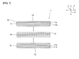
FIG. 1 is a schematic sectional view of an impact-absorbing plate according to a first embodiment. -
FIG. 2 is a schematic sectional view of an impact-absorbing plate according to a modification. -
FIG. 3 is a schematic sectional view of an impact-absorbing member according to a second embodiment. -
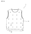
FIG. 4 is a schematic sectional view of protective clothing according to a third embodiment. -
FIG. 5 is a schematic sectional view taken along the line V-V inFIG. 4 . - One example of a preferred embodiment in which the present invention is carried out will be described below. However, the embodiment described below is merely illustrative. The present invention is in no way limited to the embodiment described below.
- In the drawings which are referred to in the embodiment etc., members having substantially the same function are referred to with the same symbol. The drawings which are referred to in the embodiment etc. are schematically described, so that the dimension ratio etc. of an article drawn in the drawing may be different from the dimension ratio etc. of the real article. The dimension ratio etc. of an article may vary among drawings. The specific dimension ratio etc. of the article should be determined by considering the following descriptions.
- As illustrated in
FIG. 1 , an impact-absorbingplate 1 includes a plurality of stretchedresin films 10. A plurality ofstretched resin films 10 are stacked along a z axis direction, i.e. a thickness direction. Thestretched resin films 10 adjacent to each other in the z axis direction are bonded to each other. Specifically, thestretched resin films 10 adjacent to each other in the z axis direction are bonded directly to each other. The impact-absorbingplate 1A is configurated by a laminate including the plurality of stretchedresin films 10 stacked and stacked to one another form. - As illustrated in
FIG. 2 , adjacent stretchedresin films 10 may be bonded to each other by anadhesive layer 13. Preferably, theadhesive layer 13 is formed of, for example, a thermoplastic resin having a low melting point. Specific examples of the thermoplastic resin that is preferably used include ethylene-vinyl acetate copolymers, PVB resins, styrene ethylene-butylene styrene block copolymers and polyethylene resins etc. - Preferably, the
stretched resin film 10 includes a crystalline polymer. In this case, the strength of thestretched resin film 10 in a stretching direction can be enhanced. Specific examples of the crystalline polymer that is preferably used include polyethylene, polypropylene, polyamide, polyacetal, polyethylene terephthalate, polybutylene terephthalate and liquid crystal polymers etc. Among them, polyethylen, polypropylene, and polyethylene terephthalate, which are easily draw-molded and are inexpensive, are more preferably used. The stretchedresin film 10 may be formed of a resin composition containing fibers. - The thickness of the
stretched resin film 10 is not particularly limited, and may be, for example, about 5 µm to 100 µm. When the thickness of thestretched resin film 10 is excessively thin, it may become difficult to mold thestretched resin film 10. When the thickness of thestretched resin film 10 is excessively thick, impact absorption performance may be deteriorated because the number of stacked films per unit thickness decreases. - The number of stretched
resin films 10 of the impact-absorbingplate 1 may be appropriately set according to a required level of blade-proof performance and bulletproof performance and a thickness of thestretched resin film 10. The number of stretchedresin films 10 of the impact-absorbingplate 1 is more preferably, for example, about 50 to 400. Generally, the thickness of the stretchedresin film 10 and the number of stacked stretchedresin films 10 are adjusted so that the thickness of the impact-absorbingplate 1 is about 2 mm to 10 mm. - A plurality of stretched
resin films 10 include biaxially stretchedresin films 12. Specifically, the impact-absorbingplate 1 includes a biaxially stretchedresin film laminate 1b including a plurality of biaxially stretchedresin films 12 stacked and bonded to one another. - A plurality of stretched
resin films 10 include uniaxially stretchedresin films resin films 12. The uniaxially stretchedresin film 11a and the uniaxially stretchedresin film 11b have mutually different stretching directions. Specifically, the stretching direction of the uniaxially stretchedresin film 11a and the stretching direction of the uniaxially stretchedresin film 11b are perpendicular to each other. - The impact-absorbing
plate 1 is configurated by uniaxially stretchedresin film laminates resin film 11a and uniaxially stretchedresin film 11b are alternately stacked and bonded to one another. First and secondprincipal surfaces plate 1 are formed of uniaxially stretchedresin film laminates principal surfaces plate 1 are formed of the uniaxially stretched resin film. - Next, action of the impact-absorbing
plate 1 will be described. When an impact is applied to theprincipal surface 1A or theprincipal surface 1B of the impact-absorbingplate 1, stretchedresin films 10 bonded are peeled by the impact. Consequently, energy of the impact is absorbed. Accordingly, for example, a crack extending through the impact-absorbingplate 1 in a thickness direction (z axis direction) is hard to be generated by energy of the applied impact. Preferably the bonding strength of adjacent stretchedresin films 10 is appropriate for obtaining preferred impact absorption performance. Specifically, a 180° peeling strength per 1 cm of width of adjacent stretchedresin films 10 is preferably 0.1 kgf to 3 kgf. When the 180° peeling strength per 1 cm of width of adjacent stretchedresin films 10 is excessively low, sufficient impact absorption performance may not be obtained at the time of collision of articles because stretchedresin films 10 are peeled during transportation or storage etc. When the 180° peeling strength per 1 cm of width of adjacent stretchedresin films 10 is excessively high, energy of impact may not be adequately absorbed because stretchedresin films 10 are not peeled when the impact is applied. - In the impact-absorbing
plate 1, a plurality of stretchedresin films 10 include biaxially stretchedresin films 12 as described above. The biaxially stretchedresin film 12 has a high strength in each of two directions in which the film is stretched. Thus, for example, even if an acute member sticks into biaxially stretchedresin films 12, the hole is hard to expand, and therefore a sharp-edged member such as an ice pick is hard to pierce the impact-absorbingplate 1 including biaxially stretchedresin films 12. Similarly, even when slashed with an edged tool, theimpact absorbing plate 1 is hard to be pierced with the edged tool. Therefore, the impact-absorbingplate 1 has excellent blade-proof performance. - For obtaining further excellent blade-proof performance, all of the stretched resin films included in the impact-absorbing plate may be biaxially stretched resin films. However, the biaxially stretched resin film has the problem that it is difficult to enhance an elastic modulus. When all of the stretched resin films are biaxially stretched resin films, it may become difficult to obtain an impact-absorbing plate which has a high elastic modulus and is excellent in bulletproof performance.
- On the other hand, the impact-absorbing
plate 1 includes uniaxially stretchedresin films resin films 2. In the case of uniaxially stretchedresin films plate 1 including uniaxially stretchedresin films resin films 2, not only excellent blade-proof performance but also excellent bulletproof performance can be achieved. - The impact-absorbing plate may include at least one of a woven fabric and a braided fabric which is stacked on the stretched resin films. The impact-absorbing plate may include at least one of a woven fabric and a braided fabric in place of the uniaxially stretched resin film. That is, the impact-absorbing plate may include at least one of a woven fabric, a braided fabric and the uniaxially stretched resin film in addition to the biaxially stretched resin film.
- As the braided fabric, for example, those formed by alternately stacking strip-shaped uniaxially stretched resin films along two or more different directions are preferably used. Specifically, for example, those formed by alternately stacking strip-shaped uniaxially stretched resin films along one direction and another direction perpendicular to the one direction, those formed by alternately stacking strip-shaped uniaxially stretched resin films along the one direction, the another direction and a direction inclined to the one direction at an angle of 45°, and the like are preferably used.
- As the woven fabric, for example, plane weaves, twill weaves, basket weaves and the like are preferably used.
- For further improving bulletproof performance of the impact-absorbing
plate 1, at least one ofprincipal surfaces plate 1 is preferably formed of the uniaxially stretchedresin film 11a or the uniaxially stretchedresin film 11b, and bothprincipal surfaces plate 1 are more preferably formed of the uniaxially stretchedresin film 11a or the uniaxially stretchedresin film 11b. - For further improving bulletproof performance of the impact-absorbing
plate 1, preferably the impact-absorbingplate 1 includes a plurality of uniaxially stretchedresin films resin film 11a and the stretching direction of the uniaxially stretchedresin film 11b are orthogonal to each other. - Similarly, for further improving bulletproof performance of the impact-absorbing
plate 1, preferably a plurality of stretchedresin films 10 include a plurality of biaxially stretchedresin films 12 whose stretching directions are mutually inclined. - For achieving excellent bulletproof performance, the total of the thicknesses of uniaxially stretched
resin films plate 1 is preferably, for example, about 0.2 mm to 1 mm. For achieving excellent blade-proof performance, the total of the thicknesses of biaxially stretchedresin films 12 of the impact-absorbingplate 1 is preferably, for example, about 1 mm to 9 mm. - Next, a method for producing the impact-absorbing
plate 1 will be described. - First, uniaxially stretched
resin films resin film 12 are provided. Uniaxially stretchedresin films - The biaxially stretched
resin film 12 can be molded using at least one of stretching methods such as, for example, an inflation molding, a tubular-type biaxial stretching method and a tender-type biaxial stretching method. The draw ratio may be, for example, about 2 to 5. - Next, uniaxially stretched
resin films resin film 12 are appropriately stacked and thermocompression-bonded, whereby the impact-absorbingplate 1 can be produced. When the temperature during thermocompression bonding is excessively high, stretchedresin films 10 may be excessively strongly fused together, or orientational relaxation of molecules in the stretchedresin film 10 may occur. On the other hand, when the temperature during thermocompression bonding is extremely low, the bonding strength of stretchedresin films 10 may become excessively low. Therefore, the temperature during thermocompression bonding is preferably approximately a temperature lower by 100°C to a temperature higher by 5°C than the melting point of the stretchedresin film 10. Specifically, when the stretchedresin film 10 is formed of high-density polyethylene, the temperature during themocompression bonding is preferably about 120°C to 130°C. When the stretchedresin film 10 is formed of polyethylene terephthalate, the temperature during themocompression bonding is preferably about 150°C to 200°C. - The stacking order of stretched
resin films 10 is not particularly limited to the stacking order in the impact-absorbingplate 1. For example, uniaxially stretched resin films and biaxially stretched resin films may be alternately stacked. In this case, for example, a uniaxially stretched resin film stretched in one direction, the biaxially stretched resin film, a uniaxially stretched resin film stretched in a direction perpendicular to the one direction, and the biaxially stretchedresin film 12 may be stacked in this order. - Another example of a preferred embodiment of the present invention will be described. In the following descriptions, members having substantially the same function with the first embodiment are referred to with the same symbol, and explanations thereof are omitted.
-
FIG. 3 is a schematic sectional view of an impact-absorbing member according to a second embodiment. - The first embodiment has been described by showing as an example the impact-absorbing
plate 1 that is a rigid body in which adjacent stretchedresin films 10 are wholly bonded to each other as one embodiment of the impact-absorbing member according to the present invention. However, the present invention is not limited to this configuration. For example, adjacent stretched resin films may at least partially kept from being not bonded to each other. - In an impact-absorbing
member 1a according to this embodiment, adjacent stretchedresin films 10 are not bonded to each other, and therefore can be relatively displaced. In each of a plurality of stretchedresin films 10, a plurality of through-holes 10a are provided at intervals from one another. A plurality of stretchedresin films 10 are stacked such that through-holes 10a of one film overlap those of another film. - A plurality of stretched
resin films 10 are bound together by bindingmembers 20 inserted in through-holes 10a. The bindingmember 20 includes apillar portion 21 and first andsecond head portions pillar portion 21 is inserted in the through-hole 10a, and extends from one side to the other side of a laminate of a plurality of stretchedresin films 10. Thefirst head portion 22a is joined to one end of thepillar portion 21, and situated at one side of the laminate of a plurality of stretchedresin films 10. Thesecond head portion 22b is joined to the other end of thepillar portion 21, and situated at the other side of the laminate of a plurality of stretchedresin films 10. The first andsecond head portions hole 10a. Therefore, stretchedresin films 10 are integrated in such a manner as to be retained by the first andsecond head portions - Preferably, the binding
member 20 is formed of a metal. In this case, excellent bulletproof performance and blade-proof performance can also be imparted to sections provided with through-holes 10a. Preferably, the first andsecond head portions hole 10a irrespective of a location in the through-hole 10a at which thepillar portion 21 is situated. - When adjacent stretched
resin films 10 are at least partially kept from being not bonded to each other as in this embodiment, the impact-absorbingmember 1a having flexibility can be provided. The impact-absorbingmember 1a having flexibility as described above is particularly suitably used in applications where flexibility or plasticity is required, such as, for example, those of clothing etc. - For obtaining higher plasticity, it is preferred that the
pillar portion 21 is thinner than the through-hole 10a, and a clearance is provided between the outer circumferential surface of thepillar portion 21 and the inner circumferential surface of the through-hole 10a. The ratio of the diameter of thepillar portion 21 to the diameter of the through-hole 10a is preferably 1.0 or less, more preferably 0.8 or less. However, when thepillar portion 21 is excessively thin, the strength of thepillar portion 21 may be excessively reduced. Therefore, the ratio of the diameter of thepillar portion 21 to the diameter of the through-hole 10a is preferably 0.6 or more. The length of thepillar portion 21 is preferably longer than the total thickness of a plurality of stacked stretchedresin films 10. The ratio of the length of thepillar portion 21 to the total thickness of a plurality of stacked stretchedresin films 10 is more preferably 1.0 or more, further preferably 1.2 or more. However, when thepillar portion 21 is excessively long, a plurality of stretchedresin films 10 may not be suitably bound. Therefore, the ratio of the length of thepillar portion 21 to the total thickness of a plurality of stacked stretchedresin films 10 is preferably 1.3 or less. - In the impact-absorbing
member 1a according to this embodiment, the stacked form of stretchedresin films 10 is substantially the same as that in the impact-absorbingmember 1 according to the first embodiment. Therefore, in this embodiment, the descriptions of the first embodiment are incorporated with regard to the stacked form of stretchedresin films 10. - In this embodiment, an example has been described in which a plurality of stretched
resin films 10 are bound using the bindingmember 20, but adjacent stretchedresin films 10 may be partially bonded to each other using an adhesive, or bonded directly to each other. -
FIG. 4 is a schematic sectional view of protective clothing according to a third embodiment.FIG. 5 is a schematic sectional view taken along the line V-V inFIG. 4 . - The impact-absorbing member according to the present invention is excellent in bulletproof performance and blade-proof performance, and therefore can be used in various applications such as, for example, those of protective clothing, protective shoes, vehicles, buildings and protectors such as shields. Particularly, an impact-absorbing member having flexibility, like the impact-absorbing
member 1a according to the second embodiment, is suitably used for protective clothing etc. - In this embodiment,
protective clothing 2 including an impact-absorbingmember 1b having flexibility as illustrated inFIG. 5 will be described. - The
protective clothing 2 includes aclothing body 30 made of cloth which forms the outer surface of theprotective clothing 2. As illustrated inFIG. 5 , the impact-absorbingmember 1b is arranged inside theclothing body 30. The impact-absorbingmember 1b has substantially the same configuration as that of the impact-absorbingmember 1a according to the second embodiment except that the stretchedresin film 10 has avent hole 10b. The impact-absorbingmember 1b is continuously arranged substantially all over theclothing body 30. - For example, when a rigid body such as a metal plate etc. is arranged inside the clothing body, the rigid body can be arranged only on a part of the clothing body. When the rigid body is arranged all over the clothing body, flexibility of the protective clothing is lost, so that it becomes difficult to put on and take off the clothing, and also movement of a person wearing the protective clothing is significantly restricted. Commonly tile-shaped rigid bodies are arranged in a matrix form at intervals from one another. In this case, bulletproof performance and blade-proof performance between rigid bodies are not secured. On the other hand, the impact-absorbing
member 1b has flexibility. Therefore, for example, even when the impact-absorbingmember 1b is continuously provided all over theclothing body 30 with no gap left, flexibility of theprotective clothing 2 is maintained. Therefore, the impact-absorbingmember 1b can be continuously and largely provided inside theclothing body 30. Accordingly, theprotective clothing 2 excellent in protective performance can be provided. - Since the stretched
resin film 10 is provided with thevent hole 10b, theprotective clothing 2 excellent in air permeability can be provided. Instead of providing thevent hole 10b, the stretchedresin film 10 may be formed of a porous material having an interconnected cell. The stretchedresin film 10 may be formed of a porous material having an interconnected cell, and provided with thevent hole 10b. - In this embodiment, vent
holes 10b of adjacent stretchedresin films 10 are provided so as not overlap each other in a stacking direction. Therefore, for example, portions having low bulletproof performance and blade-proof performance are hard to occur as compared to a case where vent holes are provided so as to overlap one another in a stacking direction. - As illustrated in
FIG. 5 , in theprotective clothing 2, theclothing body 30 and the impact-absorbingmember 1b are fixed to each other by the bindingmember 20. Between adjacent bindingmembers 20, the length of the impact-absorbingmember 1b is longer than the length of theclothing body 30. That is, the impact-absorbingmember 1b is loosely fixed to theclothing body 30 by the bindingmember 20. In this way, flexibility of theprotective clothing 2 is further enhanced. Between adjacent bindingmembers 20, the ratio of the length of the impact-absorbingmember 1b to theclothing body 30 is preferably 1.0 or more, more preferably 1.1 or more for enhancing flexibility of theprotective clothing 2. The ratio of the length of theclothing body 30 to the length of the impact-absorbingmember 1b is usually 1.2 or less. - The distance between adjacent
binding members 20 may be, for example, about 30 mm to 100 mm. When the distance between adjacentbinding members 20 is excessively short, flexibility of theprotective clothing 2 may be excessively reduced. When the distance between adjacentbinding members 20 is excessively long, handling characteristics of theprotective clothing 2 may be deteriorated. - A biaxially stretched polyester film having a thickness of 16 µm (FT16 manufactured by Teijin Limited) was cut into squares of 200 mm, and the sheets thus obtained were stacked in 150 layers. The obtained laminate was heated and pressed under a press load of 10 t using a pressing machine (30 t Pressure Pressing Machine manufactured by Toyo Seiki Seisaku-Sho, Ltd.) with the surface temperature set at 180°C. Thereafter, the setting of the surface temperature of the pressing machine was changed to 140°C and the laminate was held for 60 minutes while a press load of 10 t was maintained. The sample was cooled to room temperature while a pressure of 5 t was applied using a cooled pressing machine (30 t Pressure Pressing Machine manufactured by Toyo Seiki Seisaku-Sho, Ltd.). The thickness of the obtained biaxially stretched polyester film laminate was 2 mm.
- Two uniaxially stretched high-density polyethylene sheets with a laminate film (Forte manufactured by SEKISUI SEIKEI Co., Ltd.), which had a thickness of 0.2 mm and a width of 200 mm, were stacked such that stretching directions were orthogonal to each other, and the obtained laminate was heated and pressed under a press load of 5 t for approximately 2 minutes using a pressing machine (30 t Pressure Pressing Machine manufactured by Toyo Seiki Seisaku-Sho, Ltd.) with the surface temperature set at 125°C, thereby obtaining a uniaxially stretched resin film laminate having a thickness of 0.4 mm.
- The uniaxially stretched resin film laminate prepared as described above was stacked on both surfaces of the biaxially stretched polyester film laminate prepared as described above, with a film, which was obtained by heating and compressing to a thickness of 0.1 mm an ethylene vinyl acetate film (SP Sealant manufactured by Sekisui Film Co., Ltd.) having a thickness of 0.1 mm, interposed therebetween, and the obtained laminate was heated and pressed under a press load of 5 t for approximately 2 minutes using a pressing machine (30 t Pressure Pressing Machine manufactured by Toyo Seiki Seisaku-Sho, Ltd.) with the surface temperature set at 125°C, thereby preparing an impact-absorbing plate having a thickness of 2.9 mm.
- 14 uniaxially stretched high-density polyethylene sheets with a laminate film (Forte manufactured by SEKISUI SEIKEI Co., Ltd.), which had a thickness of 0.2 mm and a width of 200 mm, were stacked such that stretching directions were orthogonal to each other between adjacent sheets, and the obtained laminate was heated and pressed under a press load of 5 t for approximately 10 minutes using a pressing machine (30 t Pressure Pressing Machine manufactured by Toyo Seiki Seisaku-Sho, Ltd.) with the surface temperature set at 125°C, thereby preparing an impact-absorbing plate having a thickness of 2.9 mm.
- A biaxially stretched polyester film having a thickness of 16 µm (FT16 manufactured by Teijin Limited) was cut into squares of 200 mm, and the sheets thus obtained were stacked in 150 layers. Holes having a diameter of 10 mm were formed in a matrix form at intervals of 50 mm in the obtained laminate using a drill. An epoxy adhesive (Araldite 8-254-01 manufactured by AS ONE Corporation) was poured into each of a plurality of holes formed, and the laminate was left standing for 2 days to bond the stacked biaxially stretched polyester films, thereby obtaining an impact-absorbing plate.
- A cylindrical hole having a diameter of 20 mm and a depth of 30 mm was formed at one end surface of a cylindrical brass material having a diameter of 38 mm, thereby preparing a 1 kg weight provided with a cylindrical hole. An eyeleteer hilt manufactured by DEBIKA Corporation was inserted into the cylindrical hole of the weight to prepare a blade with a weight. The blade with a weight was caused to fall down from 1.5 m above the impact-absorbing plate through the inside of an aluminum cylindrical pipe having a diameter of 40 mm, which was arranged on the impact-absorbing plate arranged on a cork board having a thickness of 5 cm, thereby colliding the blade against the impact-absorbing plate. A length of a part of the blade (needle), which resultantly pierced through the impact-absorbing plate, was measured.
- As a result, the length of a part, which pierced through the impact-absorbing plate prepared in Example 1, was 6 mm. The length of a part, which pierced through the impact-absorbing plate prepared in Example 2, was 12 mm. On the other hand, the length of a part, which pierced through the impact-absorbing plate prepared in Comparative Example, was 18 mm.
-
- 1, 1a, 1b
- impact-absorbing plate
- 1A, 1B
- principal surface
- 1a, 1c
- uniaxially stretched resin film laminate
- 1b
- biaxially stretched resin film laminate
- 2
- protective clothing
- 10
- stretched resin film
- 10a
- through-hole
- 11a, 11b
- uniaxially stretched resin film
- 12
- biaxially stretched resin film
- 13
- adhesive layer
- 20
- binding member
- 21
- pillar portion
- 22a
- first head portion
- 22b
- second head portion
Claims (18)
- An impact-absorbing member comprising:a plurality of stretched resin films stacked and bonded to one another,wherein the plurality of stretched resin films include a biaxially stretched resin film.
- The impact-absorbing member according to claim 1,
wherein the plurality of stretched resin films include the biaxially stretched resin film and a uniaxially stretched resin film. - The impact-absorbing member according to claim 2,
wherein at least one of principal surfaces of a laminate of the plurality of stretched resin films is formed of the uniaxially stretched resin film. - The impact-absorbing member according to claim 2 or 3,
wherein the plurality of stretched resin films include a plurality of uniaxially stretched resin films whose stretching directions are mutually different. - The impact-absorbing member according to any one of claims 1 to 4,
further comprising at least one of a woven fabric and a braided fabric which is stacked on the plurality of stretched resin films. - The impact-absorbing member according to any one of claims 1 to 5,
wherein the plurality of stretched resin films include a plurality of biaxially stretched resin films whose stretching directions are mutually inclined. - The impact-absorbing member according to any one of claims 1 to 6,
wherein the stretched resin film includes a crystalline polymer. - The impact-absorbing member according to any one of claims 1 to 7,
wherein a 180° peeling strength per 1 cm of width of the adjacent stretched resin films is 0.1 kgf to 3 kgf. - The impact-absorbing member according to any one of claims 1 to 8,
wherein the adjacent stretched resin films are bonded directly to each other. - The impact-absorbing member according to any one of claims 1 to 8,
further comprising an adhesive layer that bonds the adjacent stretched resin films. - The impact-absorbing member according to any one of claims 1 to 8,
wherein the adjacent stretched resin films are at least partially kept from being not bonded to each other. - The impact-absorbing member according to claim 11,
wherein the stretched resin films have a through-hole, and
the plurality of stretched resin films are bound together by a binding member inserted in the through-hole. - The impact-absorbing member according to claim 12,
wherein the binding member is formed of a metal. - The impact-absorbing member according to any one of claims 1 to 13,
wherein the stretched resin films are formed of a porous material. - The impact-absorbing member according to any one of claims 1 to 14,
wherein the stretched resin film has a vent hole. - The impact-absorbing member according to claim 15,
wherein the vent hole provided in one of the stretched resin films and a vent hole provided in a stretched resin film adjacent to the one of the stretched resin films do not overlap each other. - Protective clothing comprising:
the impact-absorbing member according to any one of claims 1 to 16. - A method for producing an impact-absorbing member,
wherein a plurality of stretched resin films including a biaxially stretched resin film are stacked and thermocompression-bonded to obtain an impact-absorbing member.
Applications Claiming Priority (2)
| Application Number | Priority Date | Filing Date | Title |
|---|---|---|---|
| JP2012054528 | 2012-03-12 | ||
| PCT/JP2013/053041 WO2013136886A1 (en) | 2012-03-12 | 2013-02-08 | Impact-absorbing member, protective clothing, and process for producing impact-absorbing member |
Publications (2)
| Publication Number | Publication Date |
|---|---|
| EP2826622A1 true EP2826622A1 (en) | 2015-01-21 |
| EP2826622A4 EP2826622A4 (en) | 2015-10-07 |
Family
ID=49160805
Family Applications (1)
| Application Number | Title | Priority Date | Filing Date |
|---|---|---|---|
| EP13761723.9A Withdrawn EP2826622A4 (en) | 2012-03-12 | 2013-02-08 | IMPACT ABSORPTION ELEMENT, PROTECTIVE CLOTH, AND METHOD FOR MANUFACTURING THE IMPACT ABSORPTION ELEMENT |
Country Status (4)
| Country | Link |
|---|---|
| US (1) | US20140189922A1 (en) |
| EP (1) | EP2826622A4 (en) |
| JP (1) | JP5412008B1 (en) |
| WO (1) | WO2013136886A1 (en) |
Families Citing this family (3)
| Publication number | Priority date | Publication date | Assignee | Title |
|---|---|---|---|---|
| KR101964527B1 (en) * | 2017-09-29 | 2019-07-31 | 한국생산기술연구원 | Bullistic protection material with multi-layered structure and manufacturing method therefor |
| JP7385248B2 (en) * | 2019-08-29 | 2023-11-22 | 有限会社ポルテ | work protector |
| JPWO2022065402A1 (en) * | 2020-09-24 | 2022-03-31 |
Family Cites Families (20)
| Publication number | Priority date | Publication date | Assignee | Title |
|---|---|---|---|---|
| US1479740A (en) * | 1922-04-11 | 1924-01-01 | Reiter Lues | Connecter for loose-leaf binders |
| US2058718A (en) * | 1935-05-31 | 1936-10-27 | Bankers Box Company | Binder |
| DE3826318A1 (en) * | 1988-08-03 | 1990-02-15 | Hoechst Ag | HIGH-STRENGTH PLATE-SHAPED BODY WITH SURFACE STRUCTURE |
| JPH06321263A (en) * | 1993-05-07 | 1994-11-22 | Atsusato Kitamura | Shock absorbing packing material |
| US6048609A (en) * | 1994-03-07 | 2000-04-11 | Daicel Chemical Industries, Ltd. | Biaxially stretched styrenic resin sheet |
| HK1054349B (en) * | 2000-06-12 | 2004-12-03 | 奥利-本特‧拉斯马森 | Cross-laminate of films and method of manufacturing |
| JP4770054B2 (en) | 2001-04-20 | 2011-09-07 | 東レ株式会社 | Shock plate |
| JP3742568B2 (en) * | 2001-06-22 | 2006-02-08 | 宇明泰化工股▲ふん▼有限公司 | Polytetrafluoroethylene sheet or film, gasket tape obtained therefrom and method for producing the same |
| JP4056350B2 (en) * | 2002-06-19 | 2008-03-05 | 帝人株式会社 | Biaxially stretched multilayer laminated film and method for producing the same |
| US6841492B2 (en) * | 2002-06-07 | 2005-01-11 | Honeywell International Inc. | Bi-directional and multi-axial fabrics and fabric composites |
| US7578003B2 (en) * | 2004-01-01 | 2009-08-25 | Dsm Ip Assets B.V. | Ballistic-resistant article |
| JP2006002971A (en) * | 2004-06-16 | 2006-01-05 | Tsutsunaka Plast Ind Co Ltd | Transparent synthetic resin laminated body for protection shield |
| US20090068453A1 (en) * | 2006-10-11 | 2009-03-12 | Sengshiu Chung | Impact-resistant lightweight polymeric laminates |
| JP4871172B2 (en) * | 2007-03-02 | 2012-02-08 | 積水化学工業株式会社 | Laminated molded body |
| US7964267B1 (en) * | 2007-04-13 | 2011-06-21 | Bae Systems Tensylon H.P.M., Inc. | Ballistic-resistant panel including high modulus ultra high molecular weight polyethylene tape |
| WO2009151431A1 (en) * | 2007-10-19 | 2009-12-17 | Hardwire, Llc | Armor panel system to deflect incoming projectiles |
| JP5353405B2 (en) * | 2009-04-22 | 2013-11-27 | 東洋紡株式会社 | Laminated biaxially oriented polyamide film |
| JP5353404B2 (en) * | 2009-04-22 | 2013-11-27 | 東洋紡株式会社 | Laminated biaxially oriented polyamide film |
| JP5462746B2 (en) * | 2010-08-31 | 2014-04-02 | 積水化学工業株式会社 | Film laminate manufacturing method, film laminate and shock absorber |
| US9291433B2 (en) * | 2012-02-22 | 2016-03-22 | Cryovac, Inc. | Ballistic-resistant composite assembly |
-
2013
- 2013-02-08 WO PCT/JP2013/053041 patent/WO2013136886A1/en not_active Ceased
- 2013-02-08 EP EP13761723.9A patent/EP2826622A4/en not_active Withdrawn
- 2013-02-08 US US14/238,768 patent/US20140189922A1/en not_active Abandoned
- 2013-02-08 JP JP2013524299A patent/JP5412008B1/en not_active Expired - Fee Related
Also Published As
| Publication number | Publication date |
|---|---|
| WO2013136886A1 (en) | 2013-09-19 |
| EP2826622A4 (en) | 2015-10-07 |
| US20140189922A1 (en) | 2014-07-10 |
| JPWO2013136886A1 (en) | 2015-08-03 |
| JP5412008B1 (en) | 2014-02-12 |
Similar Documents
| Publication | Publication Date | Title |
|---|---|---|
| JP6461903B2 (en) | Vacuum panel used to attenuate shock waves in body armor | |
| EP2899016B1 (en) | Multilayered textile material for forming three dimensional objects | |
| EP2529176B1 (en) | Use of machine direction oriented films in ballistic articles | |
| KR102752702B1 (en) | Method for manufacturing laminated material, intermediate sheet and method for manufacturing composite material | |
| JP7397809B2 (en) | Shape-compatible polyethylene fabric and articles manufactured from the fabric | |
| US10655940B2 (en) | Ballistic resistant sheet and use of such a sheet | |
| KR20090058545A (en) | Method for producing a flexible panel comprising laminates of unidirectionally arranged polymer tapes | |
| EP3099996A2 (en) | Light weight trauma reducing body armor | |
| EP3242106A1 (en) | Bulletproof panel | |
| JP4517483B2 (en) | Composite reinforcing fiber substrate and preform | |
| US20140189922A1 (en) | Impact-absorbing member, protective clothing, and process for producing impact-absorbing member | |
| JP6262053B2 (en) | Foam sheet laminate, fiber-reinforced composite, and foam sheet laminate manufacturing method | |
| US20160297184A1 (en) | Ballistic Cloth Using A Unidirectional-Oriented Aramid Sheet And Polyethylene Film And Method For Manufacturing The Same | |
| JP2005164071A (en) | Bulletproof member | |
| KR102263817B1 (en) | Manufacturing method of stab proof hybrid composite structure | |
| JPH03138135A (en) | Compound material product having dimensional stability,its manufacturing method and application | |
| JP2007038609A (en) | COMPOSITE MATERIAL FOR MOLDING AND MOLDED BODY USING THE SAME | |
| CN203586949U (en) | Composite bulletproof inserting plate | |
| JP6731875B2 (en) | Fiber reinforced composite | |
| WO2019058599A1 (en) | Stab-proof laminate and stab-proof implement using same, and nonwoven fabric for stab-proof implement | |
| KR20150071128A (en) | Ballistic cloth using unidirectional aramid sheet and PE film, method of manufacturing the same | |
| EP3418047A1 (en) | Laminated board and method for processing laminated board | |
| JPH04251715A (en) | Manufacture of carbon fiber reinforced composite material | |
| JPH11320727A (en) | Protective material | |
| JP2953185B2 (en) | Waterproof sheet with nonwoven fabric and method for producing the same |
Legal Events
| Date | Code | Title | Description |
|---|---|---|---|
| PUAI | Public reference made under article 153(3) epc to a published international application that has entered the european phase |
Free format text: ORIGINAL CODE: 0009012 |
|
| 17P | Request for examination filed |
Effective date: 20140304 |
|
| AK | Designated contracting states |
Kind code of ref document: A1 Designated state(s): AL AT BE BG CH CY CZ DE DK EE ES FI FR GB GR HR HU IE IS IT LI LT LU LV MC MK MT NL NO PL PT RO RS SE SI SK SM TR |
|
| AX | Request for extension of the european patent |
Extension state: BA ME |
|
| DAX | Request for extension of the european patent (deleted) | ||
| RA4 | Supplementary search report drawn up and despatched (corrected) |
Effective date: 20150907 |
|
| RIC1 | Information provided on ipc code assigned before grant |
Ipc: B29C 55/02 20060101ALI20150901BHEP Ipc: B32B 5/04 20060101ALI20150901BHEP Ipc: B32B 27/00 20060101ALI20150901BHEP Ipc: B32B 5/02 20060101ALI20150901BHEP Ipc: B32B 3/00 20060101ALI20150901BHEP Ipc: B32B 3/06 20060101ALI20150901BHEP Ipc: B32B 7/02 20060101AFI20150901BHEP Ipc: B32B 27/12 20060101ALN20150901BHEP Ipc: B32B 5/06 20060101ALI20150901BHEP Ipc: B32B 15/08 20060101ALI20150901BHEP Ipc: B32B 7/12 20060101ALI20150901BHEP Ipc: B32B 3/26 20060101ALI20150901BHEP Ipc: B32B 5/22 20060101ALI20150901BHEP Ipc: B32B 7/00 20060101ALI20150901BHEP Ipc: B32B 1/00 20060101ALI20150901BHEP Ipc: B32B 7/04 20060101ALI20150901BHEP Ipc: B32B 7/14 20060101ALI20150901BHEP Ipc: B32B 27/08 20060101ALI20150901BHEP Ipc: B32B 27/06 20060101ALI20150901BHEP Ipc: B32B 7/10 20060101ALI20150901BHEP Ipc: B32B 15/00 20060101ALI20150901BHEP Ipc: B32B 15/04 20060101ALI20150901BHEP |
|
| GRAP | Despatch of communication of intention to grant a patent |
Free format text: ORIGINAL CODE: EPIDOSNIGR1 |
|
| INTG | Intention to grant announced |
Effective date: 20181207 |
|
| STAA | Information on the status of an ep patent application or granted ep patent |
Free format text: STATUS: THE APPLICATION IS DEEMED TO BE WITHDRAWN |
|
| 18D | Application deemed to be withdrawn |
Effective date: 20190418 |