EP2824983A1 - Method and device for transmitting ip data packet - Google Patents
Method and device for transmitting ip data packet Download PDFInfo
- Publication number
- EP2824983A1 EP2824983A1 EP13758599.8A EP13758599A EP2824983A1 EP 2824983 A1 EP2824983 A1 EP 2824983A1 EP 13758599 A EP13758599 A EP 13758599A EP 2824983 A1 EP2824983 A1 EP 2824983A1
- Authority
- EP
- European Patent Office
- Prior art keywords
- drb
- type information
- correspondence relationship
- data packet
- drb identifier
- Prior art date
- Legal status (The legal status is an assumption and is not a legal conclusion. Google has not performed a legal analysis and makes no representation as to the accuracy of the status listed.)
- Granted
Links
- 238000000034 method Methods 0.000 title claims abstract description 39
- 230000005540 biological transmission Effects 0.000 claims abstract description 16
- 238000012423 maintenance Methods 0.000 claims description 4
- 238000013507 mapping Methods 0.000 abstract description 6
- 238000010586 diagram Methods 0.000 description 10
- 230000011664 signaling Effects 0.000 description 6
- 101001100327 Homo sapiens RNA-binding protein 45 Proteins 0.000 description 5
- 102100038823 RNA-binding protein 45 Human genes 0.000 description 5
- 238000012545 processing Methods 0.000 description 5
- 230000001419 dependent effect Effects 0.000 description 3
- 238000011161 development Methods 0.000 description 2
Images


Classifications
-
- H—ELECTRICITY
- H04—ELECTRIC COMMUNICATION TECHNIQUE
- H04W—WIRELESS COMMUNICATION NETWORKS
- H04W28/00—Network traffic management; Network resource management
- H04W28/02—Traffic management, e.g. flow control or congestion control
- H04W28/0205—Traffic management, e.g. flow control or congestion control at the air interface
-
- H—ELECTRICITY
- H04—ELECTRIC COMMUNICATION TECHNIQUE
- H04L—TRANSMISSION OF DIGITAL INFORMATION, e.g. TELEGRAPHIC COMMUNICATION
- H04L47/00—Traffic control in data switching networks
- H04L47/10—Flow control; Congestion control
- H04L47/24—Traffic characterised by specific attributes, e.g. priority or QoS
- H04L47/2408—Traffic characterised by specific attributes, e.g. priority or QoS for supporting different services, e.g. a differentiated services [DiffServ] type of service
-
- H—ELECTRICITY
- H04—ELECTRIC COMMUNICATION TECHNIQUE
- H04L—TRANSMISSION OF DIGITAL INFORMATION, e.g. TELEGRAPHIC COMMUNICATION
- H04L67/00—Network arrangements or protocols for supporting network services or applications
- H04L67/50—Network services
- H04L67/60—Scheduling or organising the servicing of application requests, e.g. requests for application data transmissions using the analysis and optimisation of the required network resources
- H04L67/61—Scheduling or organising the servicing of application requests, e.g. requests for application data transmissions using the analysis and optimisation of the required network resources taking into account QoS or priority requirements
-
- H—ELECTRICITY
- H04—ELECTRIC COMMUNICATION TECHNIQUE
- H04W—WIRELESS COMMUNICATION NETWORKS
- H04W28/00—Network traffic management; Network resource management
- H04W28/02—Traffic management, e.g. flow control or congestion control
- H04W28/0252—Traffic management, e.g. flow control or congestion control per individual bearer or channel
- H04W28/0263—Traffic management, e.g. flow control or congestion control per individual bearer or channel involving mapping traffic to individual bearers or channels, e.g. traffic flow template [TFT]
-
- H—ELECTRICITY
- H04—ELECTRIC COMMUNICATION TECHNIQUE
- H04W—WIRELESS COMMUNICATION NETWORKS
- H04W72/00—Local resource management
- H04W72/02—Selection of wireless resources by user or terminal
-
- H—ELECTRICITY
- H04—ELECTRIC COMMUNICATION TECHNIQUE
- H04W—WIRELESS COMMUNICATION NETWORKS
- H04W72/00—Local resource management
- H04W72/50—Allocation or scheduling criteria for wireless resources
- H04W72/54—Allocation or scheduling criteria for wireless resources based on quality criteria
-
- H—ELECTRICITY
- H04—ELECTRIC COMMUNICATION TECHNIQUE
- H04W—WIRELESS COMMUNICATION NETWORKS
- H04W76/00—Connection management
-
- H—ELECTRICITY
- H04—ELECTRIC COMMUNICATION TECHNIQUE
- H04W—WIRELESS COMMUNICATION NETWORKS
- H04W80/00—Wireless network protocols or protocol adaptations to wireless operation
- H04W80/04—Network layer protocols, e.g. mobile IP [Internet Protocol]
-
- H—ELECTRICITY
- H04—ELECTRIC COMMUNICATION TECHNIQUE
- H04W—WIRELESS COMMUNICATION NETWORKS
- H04W88/00—Devices specially adapted for wireless communication networks, e.g. terminals, base stations or access point devices
- H04W88/02—Terminal devices
-
- H—ELECTRICITY
- H04—ELECTRIC COMMUNICATION TECHNIQUE
- H04W—WIRELESS COMMUNICATION NETWORKS
- H04W88/00—Devices specially adapted for wireless communication networks, e.g. terminals, base stations or access point devices
- H04W88/08—Access point devices
Definitions
- the present invention relates to the field of communications and particularly to a method and device for transmitting an IP data packet.
- IPv4 header there are 8 bits for representing a Type of Service (ToS), for example, in a schematic diagram of the IPv4 header illustrated in Fig.1 and a schematic diagram of the ToS field illustrated in Fig.2 ; the first three bits in the ToS field represent an IP priority, which defines 8 values depicted in Table 1; and there are further a 4-bit ToS and 1 reserved bit in the ToS field, where the 4-bit ToS represents the lowest delay D, the highest throughput T, the highest reliability R and the lowest cost C.
- the IPv6 header includes two fields related to a Quality of Service (QoS), which are a Traffic Class (TC) and a Flow Label (FL), where the Traffic Class field is 8-bit, the function of which is the same as that of the Type of Service field in the IPv4 header, for identifying a traffic class; and the 20-bit Flow Label field identifies packets of the same traffic flow.
- QoS Quality of Service
- TC Traffic Class
- FL Flow Label
- a Policy Control and Charging (PCC) architecture maps a required QoS of a session service data flow at the application level to a required QoS for an access of an IP-Connectivity Access Network (IP-CAN) to a bearer-level service of a transport network to guarantee data transmission; and this is functionally embodied on an Application Function (AF), a Policy and Charging Rule Function (PCRF), a Policy and Charging Enforcement Function (PCEF) or a Bearer Binding and Event Report Function (BBERF) and a User Equipment (UE).
- AF Application Function
- PCRF Policy and Charging Rule Function
- PCEF Policy and Charging Enforcement Function
- BBERF Bearer Binding and Event Report Function
- UE User Equipment
- the AF transmits traffic information of media-plane parameters to the PCRF via an Rx interface in the form of signaling of an AF session;
- the PCRF maps the traffic information to authorized IP QoS parameters according to an operator policy, user subscription information, etc.;
- the PCRF issues a corresponding QoS policy to the PCEF of a Packet Data Network-Gateway (PDN-GW);
- the PCEF binds a bearer according to a PCC rule and maps these parameters to QoS parameters of the particular access via a Gx or Gxx interface, e.g., QoS parameters of the EPS bearer (e.g., a QoS Class Identifier (QCI), a Guaranteed Bit Rate (GBR), a Maximum Bit Rate (MBR), etc.).
- QCI QoS Class Identifier
- GRR Guaranteed Bit Rate
- MRR Maximum Bit Rate
- the EPS bearer is the granularity, in which an Evolved Packet Core (EPC)/Evolved-Universal Terrestrial Radio Access Network (E-UTRAN) performs the QoS control, to enforce the same bearer-level packet forwarding strategy for traffic mapped to the same EPS bearer; an EPS bearer needs to traverse different network elements and interfaces and is mapped to a different underlying bearer on each of the interfaces; the respective network nodes are responsible for maintaining the identifiers of underlying bearers and their mutual binding relationship, where an eNodeB (i.e., a base station) creates binding between a radio bearer and an S1 bearer for mapping between the radio bearer and the S1 interface, and a Serving-Gateway (S-GW) creates binding between the S1 bearer and an S5/S8 bearer for mapping between the S1 bearer and the S5/S8 bearer; and finally data of the EPS bearer is concatenated over the radio bearer,
- Each EPS bearer is associated with a so-called data packet Traffic Flow Template (TFT), where the TFT includes an uplink TFT and a downlink TFT respectively located at the UE side and the Gateway (GW).
- TFT includes packet filter information, typically 5-tuple information including source and destination IP addresses, source and destination port numbers and a protocol number.
- a traffic data flow is mapped onto a corresponding EPS bearer by the GW or the UE side according to the packet filter information for the purpose of binding between the data flow and the EPS bearer.
- an implementation at the network side relates to a direct access of the base station (or through the IP gateway) to the IP network, and in this architecture, the base station is the Access Point (AP); and unlike the traditional IP network, transmission of the base station to the UE is performed via an air interface by the base station transmitting an IP data packet to the UE via the air interface while guaranteeing the QoS required for the IP data packet via the air interface.
- the base station is the Access Point (AP); and unlike the traditional IP network, transmission of the base station to the UE is performed via an air interface by the base station transmitting an IP data packet to the UE via the air interface while guaranteeing the QoS required for the IP data packet via the air interface.
- An embodiment of the invention provides a method and device for transmitting an IP data packet so as to map a QoS, required for the IP data packet, directly to a data radio bearer to thereby guarantee the QoS.
- an embodiment of the invention provides a method for transmitting an Internet Protocol, IP, data packet, the method including:
- An embodiment of the invention provides a method for transmitting an Internet Protocol, IP, data packet, the method including:
- An embodiment of the invention provides a User Equipment, UE, including:
- the embodiments of the invention have at least the following advantages over the prior art: the QoS of the IP data packet transmitted via the air interface can be guaranteed by direct mapping between the type information and the data radio bearer in the case of a direct access of the AP locally or through the IP gateway to the IP network in the embodiments of the invention.
- the first embodiment of the invention provides a method for transmitting an IP data packet, where an AP device is connected directly with an IP network by an IP interface (or through an IP gateway) and transmits an IP data packet with a UE via an air interface (that is, the AP device transmits an IP data packet to the UE via the air interface and the UE transmits an IP data packet to the AP device via the air interface); and in order to guarantee a QoS required for the IP data packet via the air interface, as illustrated in Fig.5A , the method in a flow of processing at the AP device side includes the following steps:
- an AP device obtains an IP data packet to be transmitted to a UE, where the AP device can receive, from an IP network, the IP data packet to be transmitted to the UE.
- the AP device determines, from type information of the IP data packet, a Data Radio Bearer (DRB) corresponding to the IP data packet.
- DRB Data Radio Bearer
- the type information includes but will not be limited to: a type of service carried in a header of an IPv4 data packet (8 bits in the IPv4 header to represent a Type of Service (ToS)): or a traffic class carried in a header of an IPv6 data packet (8 bits in the IPv6 header to represent a Traffic Class (TC)); or a protocol type, a source port number and a destination port number in the IPv4 data packet; or a next header, a source port number and a destination port number in the IPv6 data packet.
- ToS Type of Service
- TC Traffic Class
- the AP device needs to be provided with an IP parsing function and can parse the IP data packet for the header and obtain the type information (the type of service or the traffic class) of the IP data packet from the header of the IP data packet and further categorize the IP data packet by the type of service or the traffic class and map a result of categorization to a different data air interface bearer (i.e., DRB) to according to the attribute of the categorized IP data packet.
- DRB data air interface bearer
- the AP device determines the DRB corresponding to the IP data packet according to the type information of the IP data packet particularly as follows: the AP device inquires about a DRB identifier corresponding to the type information of the IP data packet from a pre-maintained correspondence relationship between type information and a DRB identifier and determines the DRB corresponding to the IP data packet by the DRB identifier.
- the DRB corresponding to the IP data packet can be determined finally from the maintained correspondence relationship between type information and a DRB identifier. For example, there is a correspondence relationship between type information 1 and a DRB identifier 1, and if the type information 1 is obtained from the IP data packet, then it can be determined that the DRB over which the IP data packet needs to be transmitted is a DRB corresponding to the DRB identifier 1.
- the AP device transmits the IP data packet to the UE over the determined DRB, and subsequent reception and processing by the UE will be omitted here in the embodiment of the invention.
- the AP device can know which DRB onto which the IP data packet shall be put for transmission to thereby guarantee the QoS required for the IP data packet.
- Fig.5A illustrates the flow of processing at the AP device side, and in order to ensure a QoS required for an IP data packet via an air interface, as illustrated in Fig.5B , the method in a flow of processing at the UE side can include the following steps:
- a UE obtains an IP data packet to be transmitted to an AP device, where the UE needing to transmit an IP data packet to the AP device can obtain by itself the IP data packet to be transmitted to the AP device.
- the UE determines, from type information of the IP data packet, a DRB corresponding to the IP data packet, where the type information includes but will not be limited to: a type of service carried in a header of an IPv4 data packet; or a traffic class carried in a header of an IPv6 data packet; or a protocol type, a source port number and a destination port number in the IPv4 data packet; or a next header, a source port number and a destination port number in the IPv6 data packet.
- the UE determines the DRB corresponding to the IP data packet according to the type information of the IP data packet particularly as follows: the UE inquires about a DRB identifier corresponding to the type information of the IP data packet from a pre-maintained correspondence relationship between type information and a DRB identifier and determines the DRB corresponding to the IP data packet by the DRB identifier.
- the DRB corresponding to the IP data packet can be determined finally from the maintained correspondence relationship between type information and a DRB identifier. For example, there is a correspondence relationship between type information 1 and a DRB identifier 1, and if the type information 1 is obtained from the IP data packet, then it can be determined that the DRB over which the IP data packet needs to be transmitted is a DRB corresponding to the DRB identifier 1.
- the UE transmits the IP data packet to the AP device over the determined DRB, and subsequent reception and processing by the AP device will be omitted here in the embodiment of the invention.
- the UE obtaining the IP data packet to be transmitted to the AP device can know which DRB onto which the IP data packet shall be put for transmission to thereby guarantee the QoS required for the IP data packet.
- both the AP device and the UE need to maintain the correspondence relationship between type information and a DRB identifier, and in order to maintain the correspondence relationship between type information and a DRB identifier:
- the AP device obtains and maintains the correspondence relationship between type information and a DRB identifier and notifies the UE of the correspondence relationship between type information and a DRB identifier, and the UE obtains and maintains the correspondence relationship between type information and a DRB identifier.
- the AP device obtains the correspondence relationship between type information and a DRB identifier particularly as follows: in the step 1, the AP device obtains the correspondence relationship between type information and a DRB identifier; in the step 2, when the UE is connected to the AP device, the AP device sets up the DRB for the UE using a DRB configuration, determines a DRB identifier corresponding to the setup DRB and determines a correspondence relationship between a DRB configuration and a DRB identifier; and in the step 3, the AP device determines the correspondence relationship between type information and a DRB identifier from a correspondence relationship between type information and a DRB configuration and the correspondence relationship between a DRB configuration and a DRB identifier.
- the type information particularly includes but will not be limited to a Type of Service (ToS) or a Traffic Class (TC); or a protocol type, a source port number and a destination port number in an IPv4 data packet; or a next header, a source port number and a destination port number in an IPv6 data packet.
- ToS Type of Service
- TC Traffic Class
- protocol type a protocol type, a source port number and a destination port number in an IPv4 data packet; or a next header, a source port number and a destination port number in an IPv6 data packet.
- the DRB configuration includes but will not be limited to a logical channel configuration, e.g., a logical channel priority; a Packet Data Convergence Protocol (PDCP), e.g., a Discard Timer; a Radio Link Control (RLC) protocol, e.g., an unacknowledgement mode (UM), an acknowledgement mode (AM), etc.; and the DRB needs to be distinguished by a DRBi (i.e., a DRB identifier).
- a logical channel configuration e.g., a logical channel priority
- PDCP Packet Data Convergence Protocol
- RLC Radio Link Control
- UM unacknowledgement mode
- AM acknowledgement mode
- DRBi i.e., a DRB identifier
- the AP device obtains the correspondence relationship between type information and a DRB identifier particularly as follows: the AP device obtains the correspondence relationship between type information and a DRB identifier from an Operation Administration and Maintenance (OAM) entity; or the AP device obtains the correspondence relationship between type information and a DRB identifier in a predefined manner (for example, specifies the correspondence relationship between type information and a DRB identifier directly in the protocol).
- OAM Operation Administration and Maintenance
- the correspondence relationship between type information and a DRB configuration can be determined based upon an IP priority in the type information and the logical channel priority in the DRB configuration; or the correspondence relationship between type information and a DRB configuration can be determined based upon the IP priority in the type information, ToS bit information in the type information (e.g., the lowest delay D, the highest throughput T, the highest reliability R, etc.) and the logical channel priority in the DRB configuration.
- ToS Type of Service
- TC Traffic Class
- the correspondence relationship between type information and a DRB configuration can be determined based upon the protocol type, the source port number and the destination port number in the type information and the logical channel priority in the DRB configuration; or the correspondence relationship between type information and a DRB configuration can be determined based upon the next header, the source port number and the destination port number in the type information and the logical channel priority in the DRB configuration.
- the priority 6 and the priority 7 can be used for network control data, e.g., routing; the priority 5 can be used for voice data; the priority 4 can be used for a video conference and a video stream, the priority 3 can be used for voice control data; the priority 1 and the priority 2 can be used for data traffic; and the priority 0 can be defaulted.
- the priority 5 can be used for voice data
- the priority 4 can be used for a video conference and a video stream
- the priority 3 can be used for voice control data
- the priority 1 and the priority 2 can be used for data traffic
- the priority 0 can be defaulted.
- the IP priorities 6 and 7 can correspond to network control signaling traffic; the IP priority 5 can correspond to streaming service (e.g., at the VoIP voice-level 1); the IP priority 4 can correspond to video traffic; the IP priority 3 can correspond to streaming traffic (e.g., at the VoIP voice-level 2); the IP priorities 1 and 2 can correspond to background high best-to-effort traffic; and the IP priority 0 can correspond to background low traffic.
- the categorization above can also vary with the development of traffic classes.
- the high or low logical channel priority in the DRB configuration can be mapped to an IP data packet at a different IP priority according to the correspondence relationship between type information and a DRB configuration as depicted in Table 2 to thereby schedule a different DRB at a different priority so as to guarantee a required QoS of the different DRB.
- the correspondence relationship between type information and a DRB configuration is determined based upon the IP priority in the type information, the ToS bit information in the type information and the logical channel priority in the DRB configuration, taking the IPv4 as an example, the type information is a Type of Service (ToS), and there are 3 bits for representing an IP priority, 4-bit ToS bit information and 1 reserved bit (which needs to be set to 0) in the Type of Service (ToS); and the 4-bit ToS bit information represents the lowest delay D, the highest throughput T, the highest reliability R and the lowest cost C respectively; and since the lowest cost C is not taken into account for an air interface bearer, a correspondence relationship between type information and a DRB configuration as depicted in Table 3 can be determined based upon the IP priority, the ToS bit information (including the lowest delay D, the highest throughput T and the highest reliability R) and the logical channel priority, and the AP device can obtain the correspondence relationship between type information and a DRB configuration as depicted in Table 3 from the OAM entity or specify the
- the IP priorities 6 and 7 can correspond to network control signaling traffic; the IP priority 5 and the lowest delay D, the highest throughput T and the highest reliability R being 010 can correspond to traffic with a required high throughput at the VoIP voice-level 1; the IP priority 5 and the lowest delay D, the highest throughput T and the highest reliability R being 100 or 000 can correspond to normal traffic at the VoIP voice-level 1; the IP priority 4 and the lowest delay D, the highest throughput T and the highest reliability R being 100 can correspond to video traffic with a required low delay; the IP priority 4 and the lowest delay D, the highest throughput T and the highest reliability R being 010 can correspond to normal video traffic; the IP priority 4 and the lowest delay D, the highest throughput T and the highest reliability R being 000 can correspond to video streaming (bufferable) traffic; the IP priority 3 can correspond to streaming traffic (e.g., at the VoIP voice-level 2); the IP priorities 1 and 2 can correspond to background high best-to-effort traffic; and the IP priority 0 can correspond to background low traffic.
- the high or low logical channel priority in the DRB configuration can be mapped to an IP data packet at a different IP priority and with different ToS bit information according to the correspondence relationship between type information and a DRB configuration as depicted in Table 3 to thereby schedule a different IP packet at a different priority so as to guarantee a required QoS of the different IP packet.
- a different IP packet can be mapped onto a different DRB according to the correspondence relationship between type information represented by a protocol type, a source port number and a destination port number in an IPv4 data packet, or type information represented by a next header, a source port number and a destination port number in an IPv6 data packet, and a DRB configuration.
- an IPv4 data packet including a protocol type of TCP and both source and destination port numbers being 80 corresponds to the DRB configuration in which the logical channel priority is 8, the mode is the UM and the discarder timer is 300ms; and an IPv4 data packet including a protocol type of UDP and both source and destination port numbers being 2339 (a Voice Spy) corresponds to the DRB configuration in which the logical channel priority is 7, the mode is the UM and the discarder timer is 300ms; and for some temporarily allocated port number, an IP data packet including that port number is mapped onto a default DRB to thereby accommodate a required QoS of the different IP data packet.
- 80 a Hypertext Server
- an IPv4 data packet including a protocol type of UDP and both source and destination port numbers being 2339 corresponds to the DRB configuration in which the logical channel priority is 7, the mode is the UM and the discarder timer is 300ms
- an IP data packet including that port number is mapped onto a default DRB to thereby accommodate a required
- the AP device sets up the DRB for the UE using the DRB configuration, determines the DRB identifier corresponding to the setup DRB and determines the correspondence relationship between the DRB configuration and the DRB identifier particularly as follows: since the DRB needs to be distinguished by a DRBi (i.e., a DRB identifier) and the DRB includes PDCP, RLC, logical channel configuration and other information, the DRB identifier can be allocated to the setup DRB and the correspondence relationship between a DRB configuration and a DRB identifier can be determined after the DRB is sets up for the UE using the DRB configuration.
- a DRBi i.e., a DRB identifier
- the DRB includes PDCP, RLC, logical channel configuration and other information
- the AP device determines the correspondence relationship between type information and a DRB identifier from the correspondence relationship between the type information and the DRB configuration and the correspondence relationship between a DRB configuration and a DRB identifier particularly as follows: the correspondence relationship between the type information and the DRB identifier can be determined from the correspondence relationship between the type information and the DRB configuration obtained in the step 1 and the correspondence relationship between a DRB configuration and a DRB identifier obtained in the step 2.
- the correspondence relationship (the IP priorities 6 and 7) between the type information and the DRB identifier 1 can be determined.
- the AP device notifies the UE of the correspondence relationship between type information and a DRB identifier particularly as follows: when the AP device establishes the DRB for the UE using the DRB configuration, the AP device transmits the DRB identifier corresponding to the established DRB and the type information to the UE in a Radio Resource Control (RRC) Connection Reconfigure message; or the AP device transmits the correspondence relationship between type information and a DRB identifier maintained for the UE to the UE after determining the correspondence relationship between type information and a DRB identifier.
- RRC Radio Resource Control
- the AP device transmits the DRB identifier corresponding to the setup DRB and the type information to the UE over an RRC Connection Reconfigure message
- the AP device can maintain a correspondence relationship between type information and a DRB identifier for a connected UE dependent upon the setup condition of the DRB
- the AP device can transmit the DRB identifier corresponding to the setup DRB and the type information to the UE in an RRC Connection Reconfigure message for each setup DRB (including DRB identifier, PDCP, RLC, logical channel configuration parameter and other information).
- an RRC Connection Reconfigure message can be issued by carrying the corresponding ToS value (the IP priority 5) in addition to the DRB1 and the corresponding PDCP, RLC and logical channel configuration; and the UE can maintain a correspondence relationship between the ToS value (the IP priority 5) and the DRB1 upon reception of the RRC Connection Reconfigure message; and furthermore the AP device can maintain the correspondence relationship between the ToS value (the IP priority 5) and the DRB1 for the UE upon reception of an RRC Connection Reconfigure Success message.
- the AP device transmits the correspondence relationship between type information and a DRB identifier maintained for the UE to the UE, since the AP device can maintain a correspondence relationship between type information and a DRB identifier for a connected UE dependent upon the setup condition of the DRB, the AP device can transmit the correspondence relationship between type information and a DRB identifier maintained for the UE directly to the UE in a new signaling message after the AP device maintains the correspondence relationship between type information and a DRB identifier for the UE dependent upon the setup condition of the DRB.
- the UE obtains the correspondence relationship between type information and a DRB identifier particularly as follows: the UE receives the correspondence relationship between type information and a DRB identifier notified of by the AP device; and particularly when the AP device configures the DRB for the UE using the DRB configuration, the UE receives, from the AP device, the RRC Connection Reconfigure message carrying the DRB identifier corresponding to the setup DRB and the type information; or the UE receives, from the AP device, the correspondence relationship between type information and a DRB identifier maintained by the AP device for the UE after the AP determines the correspondence relationship between type information and a DRB identifier.
- the AP device can transmit the correspondence relationship between type information and a DRB identifier to the UE in an RRC Connection Reconfigure message or a new signaling message
- the UE can obtain the correspondence relationship between type information and a DRB identifier by receiving the RRC Connection Reconfigure message or the new signaling message transmitted from the AP device.
- the AP device maintains the correspondence relationship between type information and a DRB identifier as depicted in Table 4
- the UE can obtain and maintain a correspondence relationship between type information and a DRB identifier as depicted in Table 5, that is, Table 5 is identical to Table 4 in contents.
- Table 5 Type information (IP priority) DRB identifier 5 1 4 2 3 3 2 and 1 4 0 5
- both the AP device and the UE maintain the corresponding correspondence relationship between type information and a DRB identifier; and particularly since all the corresponding PDCP, RLC, logical channel configuration and other information in the DRB are configured by the AP device for the UE, the AP device needs to maintain the correspondence relationship between type information and a DRB configuration (obtained from the OAM entity or prescribed in the protocol) and further determines from the correspondence relationship between type information and a DRB configuration and maintains the correspondence relationship between type information and a DRB identifier; and the UE only needs to maintain the correspondence relationship between type information and a DRB identifier.
- the AP device needs to subsequently remove the DRB (e.g., the DRB1) of the UE, then the correspondence relationship between the ToS value (the IP priority 5) and the DRB1 maintained at the UE side and the AP device side also needs to be removed correspondingly.
- the DRB e.g., the DRB1
- the IP priority 5 the IP priority 5
- the AP device and the UE prescribe the correspondence relationship between type information and a DRB identifier directly, for example, by prescribing the correspondence relationship between type information and a DRB configuration directly in the protocol.
- the correspondence relationship between type information and a DRB identifier can be prescribed directly at both the AP device and UE sides in a predefined manner; and since all the corresponding PDCP, RLC, logical channel configuration and other information in the DRB are configured by the AP device for the UE, the AP device needs to prescribe the correspondence relationship between type information and a DRB configuration in addition to the correspondence relationship between type information and a DRB identifier.
- the AP device can maintain a correspondence relationship between type information, a DRB configuration and a DRB identifier as depicted in Table 6, and the UE can maintain a correspondence relationship between type information and a DRB identifier as depicted in Table 7.
- IP priority DRB configuration DRB identifier 5 UM
- Discard Timer 100ms and logical channel priority 3 1 4 AM
- Discard Timer 300ms and logical channel priority 4 2 3 AM
- Discard Timer 300ms and logical channel priority 5 3 2 and 1 UM
- Discard Timer 300ms and logical channel priority 6 4 0 UM
- Discard Timer 300ms and logical channel priority 7 5
- IP priority DRB identifier 5 1 4 2 3 3 2 and 1 4 0 5
- the correspondence relationship between type information, a DRB configuration and a DRB identifier depicted in Table 6 above can be determined based upon the IP priority in the type information and the logical channel priority in the DRB configuration; or can be determined based upon the IP priority in the type information, the ToS bit information in the type information (e.g., the lowest delay D, the highest throughput T and the highest reliability R) and the logical channel priority in the DRB configuration.
- the correspondence relationship between type information, a DRB configuration and a DRB identifier can be determined based upon the 8-bit information in the Type of Service (ToS) or the Traffic Class (TC).
- the type information can alternatively be a protocol type, a source port number and a destination port number in an IPv4 data packet or a next header, a source port number and a destination port number in an IPv6 data packet.
- the AP device sets up the DRB for the UE using the DRB configuration
- the AP device needs to allocate the DRB identifier for the setup DRB according to the correspondence relationship between type information, a DRB configuration and a DRB identifier as depicted in Table 6.
- the DRB identifier 1 needs to be allocated for the setup DRB.
- an embodiment of the invention further provides an Access Point (AP) device, and as illustrated in Fig.6 , the AP device includes:
- An obtainment module 11 is configured to obtain an IP data packet to be transmitted to a UE
- a determination module 12 is configured to determine, from type information of the IP data packet, a Data Radio Bearer (DRB) corresponding to the IP data packet; and
- DRB Data Radio Bearer
- a transmission module 13 is configured to transmit the IP data packet to the UE over the DRB.
- the determination module 12 is particularly configured to inquire about a DRB identifier corresponding to the type information of the IP data packet from a pre-maintained correspondence relationship between type information and a DRB identifier and to determine the DRB corresponding to the IP data packet by the DRB identifier.
- the determination module 12 when configured to maintain the correspondence relationship between type information and a DRB identifier, is further configured to obtain a correspondence relationship between type information and a DRB configuration; and when the UE is connected to the AP device, to set up the DRB for the UE using a DRB configuration, to determine a DRB identifier corresponding to the setup DRB and to determine a correspondence relationship between a DRB configuration and a DRB identifier; and to determine the correspondence relationship between type information and a DRB identifier from the correspondence relationship between type information and a DRB configuration and the correspondence relationship between a DRB configuration and a DRB identifier; or to prescribe the correspondence relationship between type information and a DRB identifier directly with the UE.
- the determination module 12 when configured to obtain the correspondence relationship between type information and a DRB configuration, is further configured to obtain the correspondence relationship between type information and a DRB configuration from an Operation Administration and Maintenance (OAM) entity; or to obtain the correspondence relationship between type information and a DRB configuration in a predefined manner.
- OAM Operation Administration and Maintenance
- the correspondence relationship between type information and a DRB configuration is particularly a correspondence relationship between type information and a DRB configuration determined based upon an IP priority in the type information and a logical channel priority in the DRB configuration; or a correspondence relationship between type information and a DRB configuration determined based upon an IP priority in the type information, TOS bit information in the type information and a logical channel priority in the DRB configuration, where the TOS bit information in the type information is the lowest delay D, the highest throughput T and the highest reliability R.
- the transmission module 13 is further configured to transmit the DRB identifier corresponding to the setup DRB and the type information to the UE in a Radio Resource Control (RRC) Connection Reconfigure message when the DRB is set up for the UE using the DRB configuration; or to transmit the correspondence relationship between type information and a DRB identifier maintained for the UE to the UE after the correspondence relationship between type information and a DRB identifier is determined.
- RRC Radio Resource Control
- the transmission module 13 is further configured to remove the correspondence relationship between type information and a DRB identifier corresponding to the UE and instruct the UE to remove the correspondence relationship between type information and a DRB identifier corresponding to the UE when the DRB of the UE needs to be removed after the correspondence relationship between type information and a DRB identifier is determined from the correspondence relationship between type information and a DRB configuration and the correspondence relationship between a DRB configuration and a DRB identifier.
- the type information is particularly a Type of Service (ToS) carried in a header of an IPv4 data packet; or a Traffic Class (TC) carried in a header of an IPv6 data packet; or a protocol type, a source port number and a destination port number in the IPv4 data packet; or a next header, a source port number and a destination port number in the IPv6 data packet.
- ToS Type of Service
- TC Traffic Class
- the AP is connected with an IP network via an IP interface and transmits the IP data packet to the UE via an air interface.
- modules in the device according to the invention can be integrated together or can be deployed separately.
- the modules above can be integrated into a single module or can be subdivided into a plurality of sub-modules.
- an embodiment of the invention further provides a User Equipment (UE), and as illustrated in Fig.7 , the UE includes:
- An obtainment module 21 is configured to obtain an IP data packet to be transmitted to an Access Point (AP) device;
- AP Access Point
- a determination module 22 is configured to determine, from type information of the IP data packet, a Data Radio Bearer (DRB) corresponding to the IP data packet; and
- DRB Data Radio Bearer
- a transmission module 23 is configured to transmit the IP data packet to the AP device over the DRB.
- the determination module 22 is particularly configured to inquire about a DRB identifier corresponding to the type information of the IP data packet from a pre-maintained correspondence relationship between type information and a DRB identifier and to determine the DRB corresponding to the IP data packet by the DRB identifier.
- the determination module 22 when configured to maintain the correspondence relationship between type information and a DRB identifier, is further configured to further receive and maintain the correspondence relationship between type information and a DRB identifier notified of by the AP device; or to prescribe the correspondence relationship between type information and a DRB identifier directly with the AP device.
- the determination module 22 when configured to receive the correspondence relationship between type information and a DRB identifier notified of by the AP device, is further configured to receive a Radio Resource Control (RRC) Connection Reconfigure message carrying the DRB identifier corresponding to the setup DRB and the type information from the AP device when the AP device sets up the DRB for the UE using a DRB configuration; or to receive the correspondence relationship between type information and a DRB identifier maintained by the AP device for the UE from the AP device after the AP device determines the correspondence relationship between type information and a DRB identifier.
- RRC Radio Resource Control
- the determination module 22 is further configured to remove the correspondence relationship between type information and a DRB identifier corresponding to the UE upon reception of an instruction from the AP device to remove the correspondence relationship between type information and a DRB identifier corresponding to the UE after receiving and maintaining the correspondence relationship between type information and a DRB identifier notified of by the AP device.
- the type information is particularly a Type of Service (ToS) carried in a header of an IPv4 data packet; or a Traffic Class (TC) carried in a header of an IPv6 data packet; or a protocol type, a source port number and a destination port number in the IPv4 data packet; or a next header, a source port number and a destination port number in the IPv6 data packet.
- ToS Type of Service
- TC Traffic Class
- modules in the device according to the invention can be integrated together or can be deployed separately.
- the modules above can be integrated into a single module or can be subdivided into a plurality of sub-modules.
- the embodiments of the invention can be implemented in software plus a necessary general hardware platform or, of course, in hardware, although the former implementation is preferred in many cases.
- the technical solutions of the embodiments of the invention in essence or the part thereof contributing to the prior art can be embodied in the form of a software product which can be stored in a storage medium and which includes several instructions to cause a terminal device (e.g., a personal computer, a server, a network device, etc.) to perform the methods according to the respective embodiments of the invention.
- a terminal device e.g., a personal computer, a server, a network device, etc.
- modules in the apparatuses of the embodiments can be distributed in the apparatuses of the embodiments as described in the embodiments or located in one or more apparatuses different from those of the embodiments given corresponding variations.
- the modules of the foregoing embodiments can be integrated together or deployed separately or can be combined into one module or further subdivided into a plurality of sub-modules.
Landscapes
- Engineering & Computer Science (AREA)
- Computer Networks & Wireless Communication (AREA)
- Signal Processing (AREA)
- Quality & Reliability (AREA)
- Mobile Radio Communication Systems (AREA)
- Data Exchanges In Wide-Area Networks (AREA)
Abstract
Description
- This application claims priority to Chinese Patent Application No.
201210055090.5 - The present invention relates to the field of communications and particularly to a method and device for transmitting an IP data packet.
- In an IPv4 header, there are 8 bits for representing a Type of Service (ToS), for example, in a schematic diagram of the IPv4 header illustrated in
Fig.1 and a schematic diagram of the ToS field illustrated inFig.2 ; the first three bits in the ToS field represent an IP priority, which defines 8 values depicted in Table 1; and there are further a 4-bit ToS and 1 reserved bit in the ToS field, where the 4-bit ToS represents the lowest delay D, the highest throughput T, the highest reliability R and the lowest cost C.Table 1 IP priority value IP priority name 000 Routine 001 Priority 010 Immediate 011 Flash 100 Flash Override 101 Critic 110 Internetwork Control 111 Network Control - As illustrated in
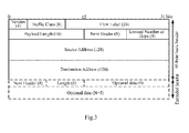
Fig.3 which is a schematic diagram of an IPv6 header, the IPv6 header includes two fields related to a Quality of Service (QoS), which are a Traffic Class (TC) and a Flow Label (FL), where the Traffic Class field is 8-bit, the function of which is the same as that of the Type of Service field in the IPv4 header, for identifying a traffic class; and the 20-bit Flow Label field identifies packets of the same traffic flow. - A Policy Control and Charging (PCC) architecture maps a required QoS of a session service data flow at the application level to a required QoS for an access of an IP-Connectivity Access Network (IP-CAN) to a bearer-level service of a transport network to guarantee data transmission; and this is functionally embodied on an Application Function (AF), a Policy and Charging Rule Function (PCRF), a Policy and Charging Enforcement Function (PCEF) or a Bearer Binding and Event Report Function (BBERF) and a User Equipment (UE).
- Particularly the AF transmits traffic information of media-plane parameters to the PCRF via an Rx interface in the form of signaling of an AF session; the PCRF maps the traffic information to authorized IP QoS parameters according to an operator policy, user subscription information, etc.; the PCRF issues a corresponding QoS policy to the PCEF of a Packet Data Network-Gateway (PDN-GW); the PCEF binds a bearer according to a PCC rule and maps these parameters to QoS parameters of the particular access via a Gx or Gxx interface, e.g., QoS parameters of the EPS bearer (e.g., a QoS Class Identifier (QCI), a Guaranteed Bit Rate (GBR), a Maximum Bit Rate (MBR), etc.).
- Moreover the EPS bearer is the granularity, in which an Evolved Packet Core (EPC)/Evolved-Universal Terrestrial Radio Access Network (E-UTRAN) performs the QoS control, to enforce the same bearer-level packet forwarding strategy for traffic mapped to the same EPS bearer; an EPS bearer needs to traverse different network elements and interfaces and is mapped to a different underlying bearer on each of the interfaces; the respective network nodes are responsible for maintaining the identifiers of underlying bearers and their mutual binding relationship, where an eNodeB (i.e., a base station) creates binding between a radio bearer and an S1 bearer for mapping between the radio bearer and the S1 interface, and a Serving-Gateway (S-GW) creates binding between the S1 bearer and an S5/S8 bearer for mapping between the S1 bearer and the S5/S8 bearer; and finally data of the EPS bearer is concatenated over the radio bearer, the S1 bearer and the S5/S8 bearer to support connectivity traffic between the UE and a Packet Data Network (PDN) so as to guarantee the required QoS.
- Each EPS bearer is associated with a so-called data packet Traffic Flow Template (TFT), where the TFT includes an uplink TFT and a downlink TFT respectively located at the UE side and the Gateway (GW). The TFT includes packet filter information, typically 5-tuple information including source and destination IP addresses, source and destination port numbers and a protocol number. A traffic data flow is mapped onto a corresponding EPS bearer by the GW or the UE side according to the packet filter information for the purpose of binding between the data flow and the EPS bearer.
- As illustrated in
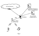
Fig.4 , in order to lower a cost at the network side and avoid congestion at the network side, an implementation at the network side relates to a direct access of the base station (or through the IP gateway) to the IP network, and in this architecture, the base station is the Access Point (AP); and unlike the traditional IP network, transmission of the base station to the UE is performed via an air interface by the base station transmitting an IP data packet to the UE via the air interface while guaranteeing the QoS required for the IP data packet via the air interface. - The inventors have identified during making of the invention at least the following problems in the prior art:
- There has been absent in the prior art of a solution to direct mapping of a QoS required for an IP data packet to an air interface bearer, thus failing to satisfy the demand for transmission of the IP data packet.
- An embodiment of the invention provides a method and device for transmitting an IP data packet so as to map a QoS, required for the IP data packet, directly to a data radio bearer to thereby guarantee the QoS.
- In order to achieve the object above, an embodiment of the invention provides a method for transmitting an Internet Protocol, IP, data packet, the method including:
- obtaining, by an Access Point, AP, device, an IP data packet to be transmitted to a User Equipment, UE;
- determining, by the AP device, a Data Radio Bearer, DRB, corresponding to the IP data packet from type information of the IP data packet; and
- transmitting, by the AP device, the IP data packet to the UE over the DRB.
- An embodiment of the invention provides a method for transmitting an Internet Protocol, IP, data packet, the method including:
- obtaining, by a User Equipment, UE, an IP data packet to be transmitted to an Access Point, AP, device;
- determining, by the UE, a Data Radio Bearer, DRB, corresponding to the IP data packet from type information of the IP data packet; and
- transmitting, by the UE, the IP data packet to the AP device over the DRB.
- An embodiment of the invention provides an Access Point, AP, device including:
- an obtainment module configured to obtain an IP data packet to be transmitted to a UE;
- a determination module configured to determine a Data Radio Bearer, DRB, corresponding to the IP data packet from type information of the IP data packet; and
- a transmission module configured to transmit the IP data packet to the UE over the DRB.
- An embodiment of the invention provides a User Equipment, UE, including:
- an obtainment module configured to obtain an IP data packet to be transmitted to an Access Point, AP, device;
- a determination module configured to determine a Data Radio Bearer, DRB, corresponding to the IP data packet from type information of the IP data packet; and
- a transmission module configured to transmit the IP data packet to the AP device over the DRB.
- The embodiments of the invention have at least the following advantages over the prior art: the QoS of the IP data packet transmitted via the air interface can be guaranteed by direct mapping between the type information and the data radio bearer in the case of a direct access of the AP locally or through the IP gateway to the IP network in the embodiments of the invention.
-
-
Fig.1 is a schematic diagram of the IPv4 header in the prior art; -
Fig.2 is a schematic diagram of the ToS field in the prior art; -
Fig. 3 is a schematic diagram of the IPv6 header in the prior art; -
Fig.4 is a schematic diagram of a direct access of the base station (or through the IP gateway) to the IP network in the prior art; -
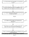
Fig.5A and Fig.5B are schematic flow charts of a method for transmitting an IP data packet according to a first embodiment of the invention; -
Fig.6 is a schematic structural diagram of an AP device according to a second embodiment of the invention; and -
Fig.7 is a schematic structural diagram of a user equipment according to a third embodiment of the invention. - The first embodiment of the invention provides a method for transmitting an IP data packet, where an AP device is connected directly with an IP network by an IP interface (or through an IP gateway) and transmits an IP data packet with a UE via an air interface (that is, the AP device transmits an IP data packet to the UE via the air interface and the UE transmits an IP data packet to the AP device via the air interface); and in order to guarantee a QoS required for the IP data packet via the air interface, as illustrated in
Fig.5A , the method in a flow of processing at the AP device side includes the following steps: - In the step 501A, an AP device obtains an IP data packet to be transmitted to a UE, where the AP device can receive, from an IP network, the IP data packet to be transmitted to the UE.
- In the
step 502A, the AP device determines, from type information of the IP data packet, a Data Radio Bearer (DRB) corresponding to the IP data packet. - In an embodiment of the invention, the type information includes but will not be limited to: a type of service carried in a header of an IPv4 data packet (8 bits in the IPv4 header to represent a Type of Service (ToS)): or a traffic class carried in a header of an IPv6 data packet (8 bits in the IPv6 header to represent a Traffic Class (TC)); or a protocol type, a source port number and a destination port number in the IPv4 data packet; or a next header, a source port number and a destination port number in the IPv6 data packet.
- Particularly the AP device needs to be provided with an IP parsing function and can parse the IP data packet for the header and obtain the type information (the type of service or the traffic class) of the IP data packet from the header of the IP data packet and further categorize the IP data packet by the type of service or the traffic class and map a result of categorization to a different data air interface bearer (i.e., DRB) to according to the attribute of the categorized IP data packet.
- In an embodiment of the invention, the AP device determines the DRB corresponding to the IP data packet according to the type information of the IP data packet particularly as follows: the AP device inquires about a DRB identifier corresponding to the type information of the IP data packet from a pre-maintained correspondence relationship between type information and a DRB identifier and determines the DRB corresponding to the IP data packet by the DRB identifier.
- Particularly since each DRB corresponds to a unique DRB identifier, the DRB corresponding to the IP data packet can be determined finally from the maintained correspondence relationship between type information and a DRB identifier. For example, there is a correspondence relationship between type information 1 and a DRB identifier 1, and if the type information 1 is obtained from the IP data packet, then it can be determined that the DRB over which the IP data packet needs to be transmitted is a DRB corresponding to the DRB identifier 1.
- In the
step 503A, the AP device transmits the IP data packet to the UE over the determined DRB, and subsequent reception and processing by the UE will be omitted here in the embodiment of the invention. - In summary, given the correspondence relationship between type information and a DRB identifier, after obtaining the IP data packet to be transmitted to the UE, the AP device can know which DRB onto which the IP data packet shall be put for transmission to thereby guarantee the QoS required for the IP data packet.
- It shall be noted that
Fig.5A above illustrates the flow of processing at the AP device side, and in order to ensure a QoS required for an IP data packet via an air interface, as illustrated inFig.5B , the method in a flow of processing at the UE side can include the following steps: - In the
step 501B, a UE obtains an IP data packet to be transmitted to an AP device, where the UE needing to transmit an IP data packet to the AP device can obtain by itself the IP data packet to be transmitted to the AP device. - In the
step 502B, the UE determines, from type information of the IP data packet, a DRB corresponding to the IP data packet, where the type information includes but will not be limited to: a type of service carried in a header of an IPv4 data packet; or a traffic class carried in a header of an IPv6 data packet; or a protocol type, a source port number and a destination port number in the IPv4 data packet; or a next header, a source port number and a destination port number in the IPv6 data packet. - In an embodiment of the invention, the UE determines the DRB corresponding to the IP data packet according to the type information of the IP data packet particularly as follows: the UE inquires about a DRB identifier corresponding to the type information of the IP data packet from a pre-maintained correspondence relationship between type information and a DRB identifier and determines the DRB corresponding to the IP data packet by the DRB identifier.
- Particularly since each DRB corresponds to a unique DRB identifier, the DRB corresponding to the IP data packet can be determined finally from the maintained correspondence relationship between type information and a DRB identifier. For example, there is a correspondence relationship between type information 1 and a DRB identifier 1, and if the type information 1 is obtained from the IP data packet, then it can be determined that the DRB over which the IP data packet needs to be transmitted is a DRB corresponding to the DRB identifier 1.
- In the
step 503B, the UE transmits the IP data packet to the AP device over the determined DRB, and subsequent reception and processing by the AP device will be omitted here in the embodiment of the invention. - In summary, given the correspondence relationship between type information and a DRB identifier, the UE obtaining the IP data packet to be transmitted to the AP device can know which DRB onto which the IP data packet shall be put for transmission to thereby guarantee the QoS required for the IP data packet.
- In order to perform the process above, both the AP device and the UE need to maintain the correspondence relationship between type information and a DRB identifier, and in order to maintain the correspondence relationship between type information and a DRB identifier:
- In a first implementation, the AP device obtains and maintains the correspondence relationship between type information and a DRB identifier and notifies the UE of the correspondence relationship between type information and a DRB identifier, and the UE obtains and maintains the correspondence relationship between type information and a DRB identifier.
- (1) The AP device obtains the correspondence relationship between type information and a DRB identifier particularly as follows: in the step 1, the AP device obtains the correspondence relationship between type information and a DRB identifier; in the step 2, when the UE is connected to the AP device, the AP device sets up the DRB for the UE using a DRB configuration, determines a DRB identifier corresponding to the setup DRB and determines a correspondence relationship between a DRB configuration and a DRB identifier; and in the
step 3, the AP device determines the correspondence relationship between type information and a DRB identifier from a correspondence relationship between type information and a DRB configuration and the correspondence relationship between a DRB configuration and a DRB identifier. - In an embodiment of the invention, the type information particularly includes but will not be limited to a Type of Service (ToS) or a Traffic Class (TC); or a protocol type, a source port number and a destination port number in an IPv4 data packet; or a next header, a source port number and a destination port number in an IPv6 data packet. The DRB configuration includes but will not be limited to a logical channel configuration, e.g., a logical channel priority; a Packet Data Convergence Protocol (PDCP), e.g., a Discard Timer; a Radio Link Control (RLC) protocol, e.g., an unacknowledgement mode (UM), an acknowledgement mode (AM), etc.; and the DRB needs to be distinguished by a DRBi (i.e., a DRB identifier).
- In the step 1, the AP device obtains the correspondence relationship between type information and a DRB identifier particularly as follows: the AP device obtains the correspondence relationship between type information and a DRB identifier from an Operation Administration and Maintenance (OAM) entity; or the AP device obtains the correspondence relationship between type information and a DRB identifier in a predefined manner (for example, specifies the correspondence relationship between type information and a DRB identifier directly in the protocol).
- Particularly in order to determine the correspondence relationship between type information and a DRB configuration, the correspondence relationship between type information and a DRB configuration can be determined based upon an IP priority in the type information and the logical channel priority in the DRB configuration; or the correspondence relationship between type information and a DRB configuration can be determined based upon the IP priority in the type information, ToS bit information in the type information (e.g., the lowest delay D, the highest throughput T, the highest reliability R, etc.) and the logical channel priority in the DRB configuration. Of course a practical application will not be limited to these two schemes as long as the correspondence relationship between type information and a DRB configuration can be determined based upon the 8-bit information in the Type of Service (ToS) or the Traffic Class (TC).
- Moreover alternatively the correspondence relationship between type information and a DRB configuration can be determined based upon the protocol type, the source port number and the destination port number in the type information and the logical channel priority in the DRB configuration; or the correspondence relationship between type information and a DRB configuration can be determined based upon the next header, the source port number and the destination port number in the type information and the logical channel priority in the DRB configuration.
- In the case that the correspondence relationship between type information and a DRB configuration is determined based upon the IP priority in the type information and the logical channel priority in the DRB configuration, taking the IPv4 as an example, the type information is a Type of Service (ToS), and there are 3 bits in the Type of Service (ToS) for representing an IP priority, a correspondence relationship between type information and a DRB configuration as depicted in Table 2 can be determined based upon the IP priority and the logical channel priority according to different traffic represented by the IP priority, and the AP device can obtain the correspondence relationship between type information and a DRB configuration as depicted in Table 2 from the OAM entity or specify the correspondence relationship between type information and a DRB configuration as depicted in Table 2 directly; and moreover the type information of the IPv6 is a Traffic Class (TC) which can be mapped similarly to the Type of Service (ToS), so a repeated description thereof will be omitted here.
Table 2 Type information (IP priority) DRB configuration 7 and 6 Logical channel priority 3, UM and Discard Timer = 100ms5 Logical channel priority 4, UM and Discard Timer =100ms 4 Logical channel priority 5, UM and Discard Timer = 300ms 3 Logical channel priority 6, UM and Discard Timer = 300ms 2 and 1 Logical channel priority 7, UM and Discard Timer = 300ms 0 Logical channel priority 8, UM and Discard Timer = 300ms - It shall be noted that among the respective IP priorities represented by the first 3 bits in the Type of Service (ToS), the priority 6 and the priority 7 can be used for network control data, e.g., routing; the priority 5 can be used for voice data; the
priority 4 can be used for a video conference and a video stream, thepriority 3 can be used for voice control data; the priority 1 and the priority 2 can be used for data traffic; and the priority 0 can be defaulted. Based upon this, the IP priorities 6 and 7 can correspond to network control signaling traffic; the IP priority 5 can correspond to streaming service (e.g., at the VoIP voice-level 1); theIP priority 4 can correspond to video traffic; theIP priority 3 can correspond to streaming traffic (e.g., at the VoIP voice-level 2); the IP priorities 1 and 2 can correspond to background high best-to-effort traffic; and the IP priority 0 can correspond to background low traffic. The categorization above can also vary with the development of traffic classes. - The high or low logical channel priority in the DRB configuration can be mapped to an IP data packet at a different IP priority according to the correspondence relationship between type information and a DRB configuration as depicted in Table 2 to thereby schedule a different DRB at a different priority so as to guarantee a required QoS of the different DRB.
- In the case that the correspondence relationship between type information and a DRB configuration is determined based upon the IP priority in the type information, the ToS bit information in the type information and the logical channel priority in the DRB configuration, taking the IPv4 as an example, the type information is a Type of Service (ToS), and there are 3 bits for representing an IP priority, 4-bit ToS bit information and 1 reserved bit (which needs to be set to 0) in the Type of Service (ToS); and the 4-bit ToS bit information represents the lowest delay D, the highest throughput T, the highest reliability R and the lowest cost C respectively; and since the lowest cost C is not taken into account for an air interface bearer, a correspondence relationship between type information and a DRB configuration as depicted in Table 3 can be determined based upon the IP priority, the ToS bit information (including the lowest delay D, the highest throughput T and the highest reliability R) and the logical channel priority, and the AP device can obtain the correspondence relationship between type information and a DRB configuration as depicted in Table 3 from the OAM entity or specify the correspondence relationship between type information and a DRB configuration as depicted in Table 3 directly; and moreover the type information of the IPv6 is a Traffic Class (TC) which can be mapped similarly to the Type of Service (ToS), so a repeated description thereof will be omitted here.
Table 3 Type information (IP priority)/first 3 bits of ToS DRB configuration 7 and 6 Logical channel priority 3, UM mode and Discard Timer = 100ms5/010 Logical channel priority 4, UM and Discard Timer = 100ms5/100 or 000 Logical channel priority 5, UM and Discard Timer = 100ms 4/100 Logical channel priority 6, UM and Discard Timer = 100ms 4/010 Logical channel priority 7, UM and Discard Timer = 150ms 4/000 Logical channel priority 8, UM and Discard Timer =300ms 3 Logical channel priority 9, UM and Discard Timer = 300ms2 and 1 Logical channel priority 10, UM and Discard Timer = 300ms 0 Logical channel priority 8, UM and Discard Timer = 300ms - It shall be noted that the IP priorities 6 and 7 can correspond to network control signaling traffic; the IP priority 5 and the lowest delay D, the highest throughput T and the highest reliability R being 010 can correspond to traffic with a required high throughput at the VoIP voice-level 1; the IP priority 5 and the lowest delay D, the highest throughput T and the highest reliability R being 100 or 000 can correspond to normal traffic at the VoIP voice-level 1; the
IP priority 4 and the lowest delay D, the highest throughput T and the highest reliability R being 100 can correspond to video traffic with a required low delay; theIP priority 4 and the lowest delay D, the highest throughput T and the highest reliability R being 010 can correspond to normal video traffic; theIP priority 4 and the lowest delay D, the highest throughput T and the highest reliability R being 000 can correspond to video streaming (bufferable) traffic; theIP priority 3 can correspond to streaming traffic (e.g., at the VoIP voice-level 2); the IP priorities 1 and 2 can correspond to background high best-to-effort traffic; and the IP priority 0 can correspond to background low traffic. The categorization above can also vary with the development of traffic classes. - The high or low logical channel priority in the DRB configuration can be mapped to an IP data packet at a different IP priority and with different ToS bit information according to the correspondence relationship between type information and a DRB configuration as depicted in Table 3 to thereby schedule a different IP packet at a different priority so as to guarantee a required QoS of the different IP packet.
- Alternatively a different IP packet can be mapped onto a different DRB according to the correspondence relationship between type information represented by a protocol type, a source port number and a destination port number in an IPv4 data packet, or type information represented by a next header, a source port number and a destination port number in an IPv6 data packet, and a DRB configuration. For example, an IPv4 data packet including a protocol type of TCP and both source and destination port numbers being 80 (a Hypertext Server) corresponds to the DRB configuration in which the logical channel priority is 8, the mode is the UM and the discarder timer is 300ms; and an IPv4 data packet including a protocol type of UDP and both source and destination port numbers being 2339 (a Voice Spy) corresponds to the DRB configuration in which the logical channel priority is 7, the mode is the UM and the discarder timer is 300ms; and for some temporarily allocated port number, an IP data packet including that port number is mapped onto a default DRB to thereby accommodate a required QoS of the different IP data packet.
- In the step 2, the AP device sets up the DRB for the UE using the DRB configuration, determines the DRB identifier corresponding to the setup DRB and determines the correspondence relationship between the DRB configuration and the DRB identifier particularly as follows: since the DRB needs to be distinguished by a DRBi (i.e., a DRB identifier) and the DRB includes PDCP, RLC, logical channel configuration and other information, the DRB identifier can be allocated to the setup DRB and the correspondence relationship between a DRB configuration and a DRB identifier can be determined after the DRB is sets up for the UE using the DRB configuration. For example, after the UE is connected to the AP device and successfully authenticated, the AP device needs to set up the DRB for the UE using the DRB configuration (the
logical channel priority 3, the UM and the discarder timer = 100ms) and allocates the DRB identifier 1 to the setup DRB, and based upon this, there is a correspondence relationship between the DRB configuration (thelogical channel priority 3, the UM and the discarder timer = 100ms) and the DRB identifier 1 for the UE. - In the
step 3, the AP device determines the correspondence relationship between type information and a DRB identifier from the correspondence relationship between the type information and the DRB configuration and the correspondence relationship between a DRB configuration and a DRB identifier particularly as follows: the correspondence relationship between the type information and the DRB identifier can be determined from the correspondence relationship between the type information and the DRB configuration obtained in the step 1 and the correspondence relationship between a DRB configuration and a DRB identifier obtained in the step 2. For example, when the correspondence relationship between the type information (the IP priorities 6 and 7) and the DRB configuration (thelogical channel priority 3, the UM and the discarder timer = 100ms) and the correspondence relationship between the DRB configuration (thelogical channel priority 3, the UM and the discarder timer = 100ms) and the DRB identifier 1 are obtained, the correspondence relationship (the IP priorities 6 and 7) between the type information and the DRB identifier 1 can be determined. There is a correspondence relationship between type information and a DRB identifier as depicted in Table 4.Table 4 Type information (IP priority) DRB identifier 5 1 4 2 3 3 2 and 1 4 0 5 - (2) The AP device notifies the UE of the correspondence relationship between type information and a DRB identifier particularly as follows: when the AP device establishes the DRB for the UE using the DRB configuration, the AP device transmits the DRB identifier corresponding to the established DRB and the type information to the UE in a Radio Resource Control (RRC) Connection Reconfigure message; or the AP device transmits the correspondence relationship between type information and a DRB identifier maintained for the UE to the UE after determining the correspondence relationship between type information and a DRB identifier.
- In the process in which the AP device transmits the DRB identifier corresponding to the setup DRB and the type information to the UE over an RRC Connection Reconfigure message, since the AP device can maintain a correspondence relationship between type information and a DRB identifier for a connected UE dependent upon the setup condition of the DRB, when the UE is connected to the AP device, the AP device can transmit the DRB identifier corresponding to the setup DRB and the type information to the UE in an RRC Connection Reconfigure message for each setup DRB (including DRB identifier, PDCP, RLC, logical channel configuration parameter and other information).
- For example, if the AP device needs to set up a new DRB with a DRBi 1 and at a corresponding ToS value (IP priority) being 5 via the air interface for the UE, then an RRC Connection Reconfigure message can be issued by carrying the corresponding ToS value (the IP priority 5) in addition to the DRB1 and the corresponding PDCP, RLC and logical channel configuration; and the UE can maintain a correspondence relationship between the ToS value (the IP priority 5) and the DRB1 upon reception of the RRC Connection Reconfigure message; and furthermore the AP device can maintain the correspondence relationship between the ToS value (the IP priority 5) and the DRB1 for the UE upon reception of an RRC Connection Reconfigure Success message.
- In the process in which the AP device transmits the correspondence relationship between type information and a DRB identifier maintained for the UE to the UE, since the AP device can maintain a correspondence relationship between type information and a DRB identifier for a connected UE dependent upon the setup condition of the DRB, the AP device can transmit the correspondence relationship between type information and a DRB identifier maintained for the UE directly to the UE in a new signaling message after the AP device maintains the correspondence relationship between type information and a DRB identifier for the UE dependent upon the setup condition of the DRB.
- (3) The UE obtains the correspondence relationship between type information and a DRB identifier particularly as follows: the UE receives the correspondence relationship between type information and a DRB identifier notified of by the AP device; and particularly when the AP device configures the DRB for the UE using the DRB configuration, the UE receives, from the AP device, the RRC Connection Reconfigure message carrying the DRB identifier corresponding to the setup DRB and the type information; or the UE receives, from the AP device, the correspondence relationship between type information and a DRB identifier maintained by the AP device for the UE after the AP determines the correspondence relationship between type information and a DRB identifier.
- In an embodiment of the invention, since the AP device can transmit the correspondence relationship between type information and a DRB identifier to the UE in an RRC Connection Reconfigure message or a new signaling message, the UE can obtain the correspondence relationship between type information and a DRB identifier by receiving the RRC Connection Reconfigure message or the new signaling message transmitted from the AP device. For example, if the AP device maintains the correspondence relationship between type information and a DRB identifier as depicted in Table 4, then the UE can obtain and maintain a correspondence relationship between type information and a DRB identifier as depicted in Table 5, that is, Table 5 is identical to Table 4 in contents.
Table 5 Type information (IP priority) DRB identifier 5 1 4 2 3 3 2 and 1 4 0 5 - Based upon the flows above, both the AP device and the UE maintain the corresponding correspondence relationship between type information and a DRB identifier; and particularly since all the corresponding PDCP, RLC, logical channel configuration and other information in the DRB are configured by the AP device for the UE, the AP device needs to maintain the correspondence relationship between type information and a DRB configuration (obtained from the OAM entity or prescribed in the protocol) and further determines from the correspondence relationship between type information and a DRB configuration and maintains the correspondence relationship between type information and a DRB identifier; and the UE only needs to maintain the correspondence relationship between type information and a DRB identifier.
- In an embodiment of the invention, if the AP device needs to subsequently remove the DRB (e.g., the DRB1) of the UE, then the correspondence relationship between the ToS value (the IP priority 5) and the DRB1 maintained at the UE side and the AP device side also needs to be removed correspondingly.
- In a second implementation, the AP device and the UE prescribe the correspondence relationship between type information and a DRB identifier directly, for example, by prescribing the correspondence relationship between type information and a DRB configuration directly in the protocol.
- In an embodiment of the invention, for an invariable correspondence relationship between type information and a DRB identifier, the correspondence relationship between type information and a DRB identifier can be prescribed directly at both the AP device and UE sides in a predefined manner; and since all the corresponding PDCP, RLC, logical channel configuration and other information in the DRB are configured by the AP device for the UE, the AP device needs to prescribe the correspondence relationship between type information and a DRB configuration in addition to the correspondence relationship between type information and a DRB identifier. Based upon this, the AP device can maintain a correspondence relationship between type information, a DRB configuration and a DRB identifier as depicted in Table 6, and the UE can maintain a correspondence relationship between type information and a DRB identifier as depicted in Table 7.
Table 6 Type information (IP priority) DRB configuration DRB identifier 5 UM, Discard Timer = 100ms and logical channel priority 31 4 AM, Discard Timer = 300ms and logical channel priority 42 3 AM, Discard Timer = 300ms and logical channel priority 5 3 2 and 1 UM, Discard Timer = 300ms and logical channel priority 6 4 0 UM, Discard Timer = 300ms and logical channel priority 7 5 Table 7 Type information (IP priority) DRB identifier 5 1 4 2 3 3 2 and 1 4 0 5 - It shall be noted that the correspondence relationship between type information, a DRB configuration and a DRB identifier depicted in Table 6 above can be determined based upon the IP priority in the type information and the logical channel priority in the DRB configuration; or can be determined based upon the IP priority in the type information, the ToS bit information in the type information (e.g., the lowest delay D, the highest throughput T and the highest reliability R) and the logical channel priority in the DRB configuration. Of course a practical application will not be limited to these two schemes as long as the correspondence relationship between type information, a DRB configuration and a DRB identifier can be determined based upon the 8-bit information in the Type of Service (ToS) or the Traffic Class (TC). Moreover the type information can alternatively be a protocol type, a source port number and a destination port number in an IPv4 data packet or a next header, a source port number and a destination port number in an IPv6 data packet.
- Moreover when the AP device sets up the DRB for the UE using the DRB configuration, the AP device needs to allocate the DRB identifier for the setup DRB according to the correspondence relationship between type information, a DRB configuration and a DRB identifier as depicted in Table 6. For example, when the DRB is set up for the UE using the DRB configuration (the
logical channel priority 3, the UM and the discard timer = 100ms), the DRB identifier 1 needs to be allocated for the setup DRB. - Based upon the same inventive idea as the method above, an embodiment of the invention further provides an Access Point (AP) device, and as illustrated in
Fig.6 , the AP device includes: - An
obtainment module 11 is configured to obtain an IP data packet to be transmitted to a UE; - A determination module 12 is configured to determine, from type information of the IP data packet, a Data Radio Bearer (DRB) corresponding to the IP data packet; and
- A
transmission module 13 is configured to transmit the IP data packet to the UE over the DRB. - The determination module 12 is particularly configured to inquire about a DRB identifier corresponding to the type information of the IP data packet from a pre-maintained correspondence relationship between type information and a DRB identifier and to determine the DRB corresponding to the IP data packet by the DRB identifier.
- The determination module 12, when configured to maintain the correspondence relationship between type information and a DRB identifier, is further configured to obtain a correspondence relationship between type information and a DRB configuration; and when the UE is connected to the AP device, to set up the DRB for the UE using a DRB configuration, to determine a DRB identifier corresponding to the setup DRB and to determine a correspondence relationship between a DRB configuration and a DRB identifier; and to determine the correspondence relationship between type information and a DRB identifier from the correspondence relationship between type information and a DRB configuration and the correspondence relationship between a DRB configuration and a DRB identifier; or to prescribe the correspondence relationship between type information and a DRB identifier directly with the UE.
- The determination module 12, when configured to obtain the correspondence relationship between type information and a DRB configuration, is further configured to obtain the correspondence relationship between type information and a DRB configuration from an Operation Administration and Maintenance (OAM) entity; or to obtain the correspondence relationship between type information and a DRB configuration in a predefined manner.
- In an embodiment of the invention, the correspondence relationship between type information and a DRB configuration is particularly a correspondence relationship between type information and a DRB configuration determined based upon an IP priority in the type information and a logical channel priority in the DRB configuration; or a correspondence relationship between type information and a DRB configuration determined based upon an IP priority in the type information, TOS bit information in the type information and a logical channel priority in the DRB configuration, where the TOS bit information in the type information is the lowest delay D, the highest throughput T and the highest reliability R.
- In an embodiment of the invention, the
transmission module 13 is further configured to transmit the DRB identifier corresponding to the setup DRB and the type information to the UE in a Radio Resource Control (RRC) Connection Reconfigure message when the DRB is set up for the UE using the DRB configuration; or to transmit the correspondence relationship between type information and a DRB identifier maintained for the UE to the UE after the correspondence relationship between type information and a DRB identifier is determined. - In an embodiment of the invention, the
transmission module 13 is further configured to remove the correspondence relationship between type information and a DRB identifier corresponding to the UE and instruct the UE to remove the correspondence relationship between type information and a DRB identifier corresponding to the UE when the DRB of the UE needs to be removed after the correspondence relationship between type information and a DRB identifier is determined from the correspondence relationship between type information and a DRB configuration and the correspondence relationship between a DRB configuration and a DRB identifier. - In an embodiment of the invention, the type information is particularly a Type of Service (ToS) carried in a header of an IPv4 data packet; or a Traffic Class (TC) carried in a header of an IPv6 data packet; or a protocol type, a source port number and a destination port number in the IPv4 data packet; or a next header, a source port number and a destination port number in the IPv6 data packet.
- In an embodiment of the invention, the AP is connected with an IP network via an IP interface and transmits the IP data packet to the UE via an air interface.
- Where the respective modules in the device according to the invention can be integrated together or can be deployed separately. The modules above can be integrated into a single module or can be subdivided into a plurality of sub-modules.
- Based upon the same inventive idea as the method above, an embodiment of the invention further provides a User Equipment (UE), and as illustrated in
Fig.7 , the UE includes: - An
obtainment module 21 is configured to obtain an IP data packet to be transmitted to an Access Point (AP) device; - A
determination module 22 is configured to determine, from type information of the IP data packet, a Data Radio Bearer (DRB) corresponding to the IP data packet; and - A transmission module 23 is configured to transmit the IP data packet to the AP device over the DRB.
- The
determination module 22 is particularly configured to inquire about a DRB identifier corresponding to the type information of the IP data packet from a pre-maintained correspondence relationship between type information and a DRB identifier and to determine the DRB corresponding to the IP data packet by the DRB identifier. - The
determination module 22, when configured to maintain the correspondence relationship between type information and a DRB identifier, is further configured to further receive and maintain the correspondence relationship between type information and a DRB identifier notified of by the AP device; or to prescribe the correspondence relationship between type information and a DRB identifier directly with the AP device. - The
determination module 22, when configured to receive the correspondence relationship between type information and a DRB identifier notified of by the AP device, is further configured to receive a Radio Resource Control (RRC) Connection Reconfigure message carrying the DRB identifier corresponding to the setup DRB and the type information from the AP device when the AP device sets up the DRB for the UE using a DRB configuration; or to receive the correspondence relationship between type information and a DRB identifier maintained by the AP device for the UE from the AP device after the AP device determines the correspondence relationship between type information and a DRB identifier. - In an embodiment of the invention, the
determination module 22 is further configured to remove the correspondence relationship between type information and a DRB identifier corresponding to the UE upon reception of an instruction from the AP device to remove the correspondence relationship between type information and a DRB identifier corresponding to the UE after receiving and maintaining the correspondence relationship between type information and a DRB identifier notified of by the AP device. - In an embodiment of the invention, the type information is particularly a Type of Service (ToS) carried in a header of an IPv4 data packet; or a Traffic Class (TC) carried in a header of an IPv6 data packet; or a protocol type, a source port number and a destination port number in the IPv4 data packet; or a next header, a source port number and a destination port number in the IPv6 data packet.
- Where the respective modules in the device according to the invention can be integrated together or can be deployed separately. The modules above can be integrated into a single module or can be subdivided into a plurality of sub-modules.
- Those skilled in the art can clearly appreciate from the foregoing description of the embodiments that the embodiments of the invention can be implemented in software plus a necessary general hardware platform or, of course, in hardware, although the former implementation is preferred in many cases. Based upon such understanding, the technical solutions of the embodiments of the invention in essence or the part thereof contributing to the prior art can be embodied in the form of a software product which can be stored in a storage medium and which includes several instructions to cause a terminal device (e.g., a personal computer, a server, a network device, etc.) to perform the methods according to the respective embodiments of the invention.
- Those skilled in the art can appreciate that the drawings are merely a schematic diagram of preferred embodiments, and the module(s) or the flow(s) may not necessarily be required to implement the embodiments of the invention.
- Those skilled in the art can appreciate that the modules in the apparatuses of the embodiments can be distributed in the apparatuses of the embodiments as described in the embodiments or located in one or more apparatuses different from those of the embodiments given corresponding variations. The modules of the foregoing embodiments can be integrated together or deployed separately or can be combined into one module or further subdivided into a plurality of sub-modules.
- The embodiments of the invention have been numbered only for the sake of a convenient description but will not suggest any superiority or inferiority of one embodiment to another.
- The foregoing disclosure is merely illustrative of several embodiments of the invention, but the invention will not be limited thereto, and any variations that can occur to those skilled in the art shall fall into the scope of the invention.
Claims (28)
- A method for transmitting an Internet Protocol, IP, data packet, wherein the method comprises:obtaining, by an Access Point, AP, device, an IP data packet to be transmitted to a User Equipment, UE;determining, by the AP device, a Data Radio Bearer, DRB, corresponding to the IP data packet from type information of the IP data packet; andtransmitting, by the AP device, the IP data packet to the UE over the DRB.
- The method according to claim 1, wherein determining, by the AP device, the DRB corresponding to the IP data packet from type information of the IP data packet comprises:inquiring, by the AP device, about a DRB identifier corresponding to the type information of the IP data packet from a pre-maintained correspondence relationship between type information and a DRB identifier and determining the DRB corresponding to the IP data packet by the DRB identifier.
- The method according to claim 2, wherein maintaining, by the AP device, the correspondence relationship between type information and a DRB identifier comprises:obtaining, by the AP device, a correspondence relationship between type information and a DRB configuration; and when the UE is connected to the AP device, setting up the DRB for the UE using the DRB configuration, determining a DRB identifier corresponding to the setup DRB and determining a correspondence relationship between a DRB configuration and a DRB identifier; and determining the correspondence relationship between type information and a DRB identifier from the correspondence relationship between type information and a DRB configuration and the correspondence relationship between a DRB configuration and a DRB identifier; orprescribing the correspondence relationship between type information and a DRB identifier by the AP device and the UE.
- The method according to claim 3, wherein obtaining, by the AP device, the correspondence relationship between type information and a DRB configuration comprises:obtaining, by the AP device, the correspondence relationship between type information and a DRB configuration from an Operation Administration and Maintenance, OAM, entity; orobtaining, by the AP device, the correspondence relationship between type information and a DRB configuration in a predefined manner.
- The method according to claim 3, wherein the method further comprises:transmitting, by the AP device, the DRB identifier corresponding to the setup DRB and the type information to the UE in a Radio Resource Control, RRC, Connection Reconfigure message when setting up the DRB for the UE using the DRB configuration; ortransmitting, by the AP device, the correspondence relationship between type information and a DRB identifier maintained for the UE to the UE after determining the correspondence relationship between type information and a DRB identifier.
- The method according to claim 3, wherein after the AP device determines the correspondence relationship between type information and a DRB identifier from the correspondence relationship between type information and a DRB configuration and the correspondence relationship between a DRB configuration and a DRB identifier, the method further comprises:when the AP device needs to remove the DRB of the UE, removing, by the AP device, the correspondence relationship between type information and a DRB identifier corresponding to the UE and instructing the UE to remove the correspondence relationship between type information and a DRB identifier corresponding to the UE.
- The method according to any one of claims 1 to 6, wherein the type information is particularly a Type of Service, ToS, carried in a header of an IPv4 data packet; or a Traffic Class, TC, carried in a header of an IPv6 data packet; or a protocol type, a source port number and a destination port number in the IPv4 data packet; or a next header, a source port number and a destination port number in the IPv6 data packet.
- The method according to any one of claims 1 to 6, wherein the AP device is connected with an IP network via an IP interface and transmits the IP data packet to the UE via an air interface.
- A method for transmitting an Internet Protocol, IP, data packet, wherein the method comprises:obtaining, by a User Equipment, UE, an IP data packet to be transmitted to an Access Point, AP, device;determining, by the UE, a Data Radio Bearer, DRB, corresponding to the IP data packet from type information of the IP data packet; andtransmitting, by the UE, the IP data packet to the AP device over the DRB.
- The method according to claim 9, wherein determining, by the UE, the Data Radio Bearer, DRB, corresponding to the IP data packet from type information of the IP data packet comprises:inquiring, by the UE, about a DRB identifier corresponding to the type information of the IP data packet from a pre-maintained correspondence relationship between type information and a DRB identifier and determining the DRB corresponding to the IP data packet by the DRB identifier.
- The method according to claim 10, wherein maintaining, by the UE, the correspondence relationship between type information and a DRB identifier comprises:receiving and maintaining, by the UE, the correspondence relationship between type information and a DRB identifier notified of by the AP device; orprescribing, by the UE and AP device, the correspondence relationship between type information and a DRB identifier directly.
- The method according to claim 11, wherein receiving, by the UE, the correspondence relationship between type information and a DRB identifier notified of by the AP device comprises:receiving, by the UE, a Radio Resource Control, RRC, Connection Reconfigure message carrying the DRB identifier corresponding to the setup DRB and the type information from the AP device when the AP device sets up the DRB for the UE using a DRB configuration; orreceiving, by the UE, the correspondence relationship between type information and a DRB identifier maintained by the AP device for the UE from the AP device after the AP device determines the correspondence relationship between type information and a DRB identifier.
- The method according to claim 11, wherein after the UE receives and maintains the correspondence relationship between type information and a DRB identifier notified of by the AP device, the method further comprises:removing, by the UE, the correspondence relationship between type information and a DRB identifier corresponding to the UE when the UE receives an instruction from the AP device to remove the correspondence relationship between type information and a DRB identifier corresponding to the UE.
- The method according to any one of claims 9 to 13, wherein the type information is particularly a Type of Service, ToS, carried in a header of an IPv4 data packet; or a Traffic Class, TC, carried in a header of an IPv6 data packet; or a protocol type, a source port number and a destination port number in the IPv4 data packet; or a next header, a source port number and a destination port number in the IPv6 data packet.
- An Access Point, AP, device, wherein the AP device comprises:an obtainment module configured to obtain an IP data packet to be transmitted to a UE;a determination module configured to determine a Data Radio Bearer, DRB, corresponding to the IP data packet from type information of the IP data packet; anda transmission module configured to transmit the IP data packet to the UE over the DRB.
- The AP device according to claim 15, wherein:the determination module is particularly configured to inquire about a DRB identifier corresponding to the type information of the IP data packet from a pre-maintained correspondence relationship between type information and a DRB identifier and to determine the DRB corresponding to the IP data packet by the DRB identifier.
- The AP device according to claim 16, wherein:when the determination module is configured to maintain the correspondence relationship between type information and a DRB identifier, the determination module is further configured to obtain a correspondence relationship between type information and a DRB configuration; and when the UE is connected to the AP device, to set up the DRB for the UE using a DRB configuration, to determine a DRB identifier corresponding to the setup DRB and to determine a correspondence relationship between a DRB configuration and a DRB identifier; and to determine the correspondence relationship between type information and a DRB identifier from the correspondence relationship between type information and a DRB configuration and the correspondence relationship between a DRB configuration and a DRB identifier; orto prescribe the correspondence relationship between type information and a DRB identifier directly with the UE.
- The AP device according to claim 17, wherein:when the determination module is configured to obtain the correspondence relationship between type information and a DRB configuration, the determination module is further configured to obtain the correspondence relationship between type information and a DRB configuration from an Operation Administration and Maintenance, OAM, entity; orto obtain the correspondence relationship between type information and a DRB configuration in a predefined manner.
- The AP device according to claim 17, wherein:the transmission module is further configured to transmit the DRB identifier corresponding to the setup DRB and the type information to the UE in a Radio Resource Control, RRC, Connection Reconfigure message when the DRB is set up for the UE using the DRB configuration; orto transmit the correspondence relationship between type information and a DRB identifier maintained for the UE to the UE after the correspondence relationship between type information and a DRB identifier is determined.
- The AP device according to claim 17, wherein:the transmission module is further configured to remove the correspondence relationship between type information and a DRB identifier corresponding to the UE and instruct the UE to remove the correspondence relationship between type information and a DRB identifier corresponding to the UE when the DRB of the UE needs to be removed after the correspondence relationship between type information and a DRB identifier is determined from the correspondence relationship between type information and a DRB configuration and the correspondence relationship between a DRB configuration and a DRB identifier.
- The AP device according to any one of claims 15 to 20, wherein the type information is particularly a Type of Service, ToS, carried in a header of an IPv4 data packet; or a Traffic Class, TC, carried in a header of an IPv6 data packet; or a protocol type, a source port number and a destination port number in the IPv4 data packet; or a next header, a source port number and a destination port number in the IPv6 data packet.
- The AP device according to any one of claims 15 to 20, wherein the AP device is connected with an IP network via an IP interface and transmits the IP data packet to the UE via an air interface.
- A User Equipment, UE, wherein the UE comprises:an obtainment module configured to obtain an IP data packet to be transmitted to an Access Point, AP, device;a determination module configured to determine a Data Radio Bearer, DRB, corresponding to the IP data packet from type information of the IP data packet; anda transmission module configured to transmit the IP data packet to the AP device over the DRB.
- The UE according to claim 23, wherein:the determination module is particularly configured to inquire about a DRB identifier corresponding to the type information of the IP data packet from a pre-maintained correspondence relationship between type information and a DRB identifier and to determine the DRB corresponding to the IP data packet by the DRB identifier.
- The UE according to claim 24, wherein:when the determination module is configured to maintain the correspondence relationship between type information and a DRB identifier, the determination module is further configured to receive and maintain the correspondence relationship between type information and a DRB identifier notified of by the AP device; orto prescribe the correspondence relationship between type information and a DRB identifier directly with the AP device.
- The UE according to claim 25, wherein:when the determination module is configured to receive the correspondence relationship between type information and a DRB identifier notified of by the AP device, the determination module is further configured to receive a Radio Resource Control, RRC, Connection Reconfigure message carrying the DRB identifier corresponding to the setup DRB and the type information from the AP device when the AP device sets up the DRB for the UE using a DRB configuration; orto receive the correspondence relationship between type information and a DRB identifier maintained by the AP device for the UE from the AP device after the AP device determines the correspondence relationship between type information and a DRB identifier.
- The UE according to claim 25, wherein:the determination module is further configured to remove the correspondence relationship between type information and a DRB identifier corresponding to the UE upon reception of an instruction from the AP device to remove the correspondence relationship between type information and a DRB identifier corresponding to the UE after receiving and maintaining the correspondence relationship between type information and a DRB identifier notified of by the AP device.
- The UE according to any one of claims 23 to 27, wherein the type information is particularly a Type of Service, ToS, carried in a header of an IPv4 data packet; or a Traffic Class, TC, carried in a header of an IPv6 data packet; or a protocol type, a source port number and a destination port number in the IPv4 data packet; or a next header, a source port number and a destination port number in the IPv6 data packet.
Applications Claiming Priority (2)
| Application Number | Priority Date | Filing Date | Title |
|---|---|---|---|
| CN201210055090.5A CN102612095B (en) | 2012-03-05 | 2012-03-05 | Transmission method and equipment of IP data packet |
| PCT/CN2013/072140 WO2013131458A1 (en) | 2012-03-05 | 2013-03-04 | Method and device for transmitting ip data packet |
Publications (3)
| Publication Number | Publication Date |
|---|---|
| EP2824983A1 true EP2824983A1 (en) | 2015-01-14 |
| EP2824983A4 EP2824983A4 (en) | 2015-03-04 |
| EP2824983B1 EP2824983B1 (en) | 2016-09-14 |
Family
ID=46529184
Family Applications (1)
| Application Number | Title | Priority Date | Filing Date |
|---|---|---|---|
| EP13758599.8A Active EP2824983B1 (en) | 2012-03-05 | 2013-03-04 | Method and device for transmitting ip data packet |
Country Status (4)
| Country | Link |
|---|---|
| US (1) | US10271238B2 (en) |
| EP (1) | EP2824983B1 (en) |
| CN (1) | CN102612095B (en) |
| WO (1) | WO2013131458A1 (en) |
Cited By (2)
| Publication number | Priority date | Publication date | Assignee | Title |
|---|---|---|---|---|
| EP3355641A1 (en) * | 2017-01-25 | 2018-08-01 | Acer Incorporated | Method of mapping data packets and related apparatuses using the same |
| EP4096288B1 (en) | 2016-08-01 | 2024-10-30 | Samsung Electronics Co., Ltd. | Method and apparatus for managing data communication in wireless communication network |
Families Citing this family (34)
| Publication number | Priority date | Publication date | Assignee | Title |
|---|---|---|---|---|
| CN102612095B (en) * | 2012-03-05 | 2014-08-20 | 电信科学技术研究院 | Transmission method and equipment of IP data packet |
| CN104105219B (en) * | 2013-04-01 | 2017-09-01 | 电信科学技术研究院 | A kind of data transmission method and device |
| US9277580B2 (en) | 2013-09-30 | 2016-03-01 | At&T Intellectual Property I, L.P. | Non-cellular link integration with cellular networks |
| RU2598337C2 (en) * | 2014-12-19 | 2016-09-20 | Закрытое акционерное общество "Лаборатория Касперского" | System and method of selecting means of interception of data transmitted over network |
| US9781652B2 (en) * | 2015-02-05 | 2017-10-03 | Mediatek Inc. | Method and apparatus of LWA PDU routing |
| US10531329B2 (en) * | 2015-04-13 | 2020-01-07 | Samsung Electronics Co., Ltd. | Method and apparatus for controlling relay traffic in wireless communication system supporting D2D communication |
| KR102333510B1 (en) * | 2016-03-30 | 2021-12-01 | 아이디에이씨 홀딩스, 인크. | Standalone L2 processing and control architecture of 5G flexible RAT system |
| CN113038552B (en) | 2016-09-30 | 2022-02-01 | 华为技术有限公司 | Communication method, base station and terminal |
| CN108156633A (en) * | 2016-12-06 | 2018-06-12 | 中兴通讯股份有限公司 | Data flow remaps method and device and user equipment, RAN equipment |
| WO2018103009A1 (en) * | 2016-12-07 | 2018-06-14 | 华为技术有限公司 | Method for deleting data radio bearer, user equipment and access network function entity |
| CN108616925B (en) * | 2016-12-13 | 2023-03-21 | 中兴通讯股份有限公司 | Data stream processing method and device |
| CN108366397B (en) * | 2017-01-26 | 2024-02-23 | 中兴通讯股份有限公司 | Data mapping method and device and wireless device |
| CN109005127B (en) * | 2017-02-03 | 2020-03-10 | 华为技术有限公司 | A QoS flow processing method, device and communication system |
| CN108430077B (en) * | 2017-02-14 | 2021-09-14 | 中国移动通信有限公司研究院 | Method for identifying service quality and wireless access network element equipment |
| CN106879072A (en) * | 2017-02-24 | 2017-06-20 | 苏州蜗牛数字科技股份有限公司 | A kind of multichannel mobile data passage realizes the system and method for data distribution service |
| CN108632879A (en) * | 2017-03-15 | 2018-10-09 | 中国移动通信有限公司研究院 | A kind of sending method of data, base station and terminal |
| RU2737955C1 (en) * | 2017-03-22 | 2020-12-07 | Гуандун Оппо Мобайл Телекоммьюникейшнс Корп., Лтд. | Uplink transmission method, an end device and a network device |
| WO2018174631A1 (en) * | 2017-03-23 | 2018-09-27 | Samsung Electronics Co., Ltd. | Method and apparatus for reducing processing load between terminal and base station when applying new qos model in next-generation mobile communication system |
| CN108966282B (en) * | 2017-03-24 | 2019-11-19 | 华为技术有限公司 | Data transmission method and device |
| KR102359746B1 (en) * | 2017-06-05 | 2022-02-10 | 삼성전자 주식회사 | Method and apparatus for transmitting data by inactive mode terminal in next generation mobile communication system |
| EP4210380B1 (en) | 2017-06-05 | 2025-12-31 | Samsung Electronics Co., Ltd. | METHOD AND DEVICE FOR CONFIGURING A PDCP DEVICE AND SDAP DEVICE IN A NEXT GENERATION MOBILE COMMUNICATIONS SYSTEM |
| KR102385420B1 (en) * | 2017-06-15 | 2022-04-12 | 삼성전자 주식회사 | Method and apparatus for reporting network requested buffer status report in next generation mobile communication system |
| CN109451828B (en) * | 2017-07-25 | 2022-05-10 | 北京小米移动软件有限公司 | Downlink data packet configuration method and device |
| CN109548160A (en) * | 2017-08-08 | 2019-03-29 | 中国移动通信有限公司研究院 | Data transmission method, device, relevant device and computer readable storage medium |
| CN110324907B (en) * | 2018-03-30 | 2021-05-25 | 电信科学技术研究院有限公司 | Service bearer configuration method and device |
| CN110248396B (en) * | 2019-06-21 | 2021-10-22 | 惠州Tcl移动通信有限公司 | Wireless network multi-access-point selection method, intelligent terminal and storage medium |
| JP7317236B2 (en) * | 2019-12-13 | 2023-07-28 | 北京小米移動軟件有限公司 | DATA PROCESSING METHOD, DATA PROCESSING DEVICE, COMMUNICATION DEVICE, AND STORAGE MEDIUM |
| CN113810949B (en) * | 2020-06-12 | 2024-11-19 | 华为技术有限公司 | Data transmission method and device |
| CN111865963B (en) * | 2020-07-16 | 2022-02-25 | 郑州信大捷安信息技术股份有限公司 | IP data packet processing method and system based on IP option |
| WO2022067525A1 (en) * | 2020-09-29 | 2022-04-07 | 华为技术有限公司 | Service state indication method, base station, and terminal |
| CN115842787A (en) * | 2021-09-17 | 2023-03-24 | 中国移动通信有限公司研究院 | Data transmission method and equipment |
| WO2023184545A1 (en) * | 2022-04-02 | 2023-10-05 | Oppo广东移动通信有限公司 | Data transmission method and apparatus, and communication device |
| CN118283733A (en) * | 2022-12-30 | 2024-07-02 | 华为技术有限公司 | A data transmission method, a communication device and a communication system |
| CN119383663A (en) * | 2023-07-18 | 2025-01-28 | 展讯通信(上海)有限公司 | Data reporting method, configuration method and device, and computer-readable storage medium |
Family Cites Families (20)
| Publication number | Priority date | Publication date | Assignee | Title |
|---|---|---|---|---|
| CN1992671B (en) * | 2005-12-28 | 2010-08-11 | 上海原动力通信科技有限公司 | Method for transmitting IP header compressed data packets in the third generation evolution system |
| JP4703445B2 (en) * | 2006-03-20 | 2011-06-15 | 株式会社エヌ・ティ・ティ・ドコモ | Host station and packet transmission method |
| US7855958B2 (en) * | 2006-08-03 | 2010-12-21 | Alcatel-Lucent Usa Inc. | Determining priority of bearer channels in a wireless telecommunications network |
| JP5032598B2 (en) * | 2007-03-21 | 2012-09-26 | テレフオンアクチーボラゲット エル エム エリクソン(パブル) | Selective packet forwarding for LTE mobility |
| ECSP077925A (en) | 2007-04-30 | 2008-11-27 | Loteria De Concepcion | System and method of production, distribution, logistics and printing of tickets for lotteries by means of a printing system for a first colorful printing, a plurality of tickets made of substrate for the first printing; and facts of their |
| JP5309708B2 (en) * | 2008-06-16 | 2013-10-09 | 富士通株式会社 | Mobile station and data transmission method |
| CN101932102B (en) * | 2009-06-19 | 2013-01-23 | 华为技术有限公司 | Service bearer mapping method and communication device |
| CN101931936B (en) * | 2009-06-22 | 2014-01-01 | 中兴通讯股份有限公司 | Method, system and terminal for transmitting business data and user data processing entity |
| EP2282575A1 (en) | 2009-08-04 | 2011-02-09 | Panasonic Corporation | Channel quality reporting in a mobile communications system |
| WO2011040751A2 (en) | 2009-09-30 | 2011-04-07 | Lg Electronics Inc. | Apparatus and method for transmitting uplink control information |
| CN102714877B (en) | 2010-01-08 | 2016-05-04 | 交互数字专利控股公司 | Method and apparatus for performing discontinuous reception and/or discontinuous transmission for multi-carrier/multi-cell operation |
| CN102238743A (en) * | 2010-05-05 | 2011-11-09 | 联芯科技有限公司 | Multiplex bearer management method and device |
| US8514756B1 (en) * | 2010-10-15 | 2013-08-20 | Juniper Networks, Inc. | Collectively addressing wireless devices |
| EP3249996A1 (en) * | 2011-04-01 | 2017-11-29 | InterDigital Patent Holdings, Inc. | Method and apparatus for controlling connectivity to a network |
| US8817690B2 (en) * | 2011-04-04 | 2014-08-26 | Qualcomm Incorporated | Method and apparatus for scheduling network traffic in the presence of relays |
| JP5325928B2 (en) | 2011-05-02 | 2013-10-23 | 株式会社エヌ・ティ・ティ・ドコモ | Channel state information notification method, radio base station apparatus, user terminal, and radio communication system |
| CA2768483C (en) * | 2011-12-30 | 2019-08-20 | Sandvine Incorporated Ulc | Systems and methods for managing quality of service |
| CN102612095B (en) * | 2012-03-05 | 2014-08-20 | 电信科学技术研究院 | Transmission method and equipment of IP data packet |
| CN102612096B (en) | 2012-03-06 | 2014-10-29 | 电信科学技术研究院 | IP (internet protocol) data packet transmission method and IP packet transmission equipment |
| US8958422B2 (en) * | 2012-03-17 | 2015-02-17 | Blackberry Limited | Handling packet data convergence protocol data units |
-
2012
- 2012-03-05 CN CN201210055090.5A patent/CN102612095B/en active Active
-
2013
- 2013-03-04 WO PCT/CN2013/072140 patent/WO2013131458A1/en not_active Ceased
- 2013-03-04 US US14/383,104 patent/US10271238B2/en active Active
- 2013-03-04 EP EP13758599.8A patent/EP2824983B1/en active Active
Cited By (3)
| Publication number | Priority date | Publication date | Assignee | Title |
|---|---|---|---|---|
| EP4096288B1 (en) | 2016-08-01 | 2024-10-30 | Samsung Electronics Co., Ltd. | Method and apparatus for managing data communication in wireless communication network |
| EP3355641A1 (en) * | 2017-01-25 | 2018-08-01 | Acer Incorporated | Method of mapping data packets and related apparatuses using the same |
| TWI717582B (en) * | 2017-01-25 | 2021-02-01 | 宏碁股份有限公司 | Method of mapping data packets and related apparatuses using the same |
Also Published As
| Publication number | Publication date |
|---|---|
| US20150071059A1 (en) | 2015-03-12 |
| EP2824983B1 (en) | 2016-09-14 |
| CN102612095B (en) | 2014-08-20 |
| US10271238B2 (en) | 2019-04-23 |
| EP2824983A4 (en) | 2015-03-04 |
| CN102612095A (en) | 2012-07-25 |
| WO2013131458A1 (en) | 2013-09-12 |
Similar Documents
| Publication | Publication Date | Title |
|---|---|---|
| EP2824983B1 (en) | Method and device for transmitting ip data packet | |
| US11284288B2 (en) | Method and apparatus for microslicing wireless communication networks with device groups, service level objectives, and load/admission control | |
| US10952094B2 (en) | AT commands for 5G QoS management | |
| US10972934B2 (en) | End-to-end prioritization for mobile base station | |
| US20220303825A1 (en) | Data transmission method and apparatus | |
| EP2441211B1 (en) | Performance monitoring in a communication network | |
| US9521679B2 (en) | Systems and methods for implementing reflective EPS bearers to ensure uplink quality of service | |
| EP3065451B1 (en) | Congestion mitigation for roamers | |
| US20160150439A1 (en) | Support of quality of service control in a mobile communication system | |
| EP3162114A1 (en) | Direct rate adaptation for an end-to-end communication path by a cellular network node | |
| US20150195202A1 (en) | Mobile terminal, control node, packet transfer node, and method for controlling congestion | |
| US10484906B2 (en) | Method and apparatus for applying different priorities to packets | |
| CN107396401A (en) | Data transmission method for uplink and device | |
| CN102612096A (en) | IP (internet protocol) data packet transmission method and IP packet transmission equipment | |
| CN108306843B (en) | Service data stream transmission method, system and PGW | |
| US20150334628A1 (en) | Method and device for transferring data traffic |
Legal Events
| Date | Code | Title | Description |
|---|---|---|---|
| PUAI | Public reference made under article 153(3) epc to a published international application that has entered the european phase |
Free format text: ORIGINAL CODE: 0009012 |
|
| 17P | Request for examination filed |
Effective date: 20140917 |
|
| AK | Designated contracting states |
Kind code of ref document: A1 Designated state(s): AL AT BE BG CH CY CZ DE DK EE ES FI FR GB GR HR HU IE IS IT LI LT LU LV MC MK MT NL NO PL PT RO RS SE SI SK SM TR |
|
| AX | Request for extension of the european patent |
Extension state: BA ME |
|
| A4 | Supplementary search report drawn up and despatched |
Effective date: 20150129 |
|
| RIC1 | Information provided on ipc code assigned before grant |
Ipc: H04W 72/08 20090101AFI20150123BHEP |
|
| DAX | Request for extension of the european patent (deleted) | ||
| 17Q | First examination report despatched |
Effective date: 20151019 |
|
| GRAP | Despatch of communication of intention to grant a patent |
Free format text: ORIGINAL CODE: EPIDOSNIGR1 |
|
| INTG | Intention to grant announced |
Effective date: 20160329 |
|
| GRAS | Grant fee paid |
Free format text: ORIGINAL CODE: EPIDOSNIGR3 |
|
| GRAA | (expected) grant |
Free format text: ORIGINAL CODE: 0009210 |
|
| AK | Designated contracting states |
Kind code of ref document: B1 Designated state(s): AL AT BE BG CH CY CZ DE DK EE ES FI FR GB GR HR HU IE IS IT LI LT LU LV MC MK MT NL NO PL PT RO RS SE SI SK SM TR |
|
| REG | Reference to a national code |
Ref country code: GB Ref legal event code: FG4D |
|
| REG | Reference to a national code |
Ref country code: CH Ref legal event code: EP |
|
| REG | Reference to a national code |
Ref country code: IE Ref legal event code: FG4D |
|
| REG | Reference to a national code |
Ref country code: AT Ref legal event code: REF Ref document number: 830200 Country of ref document: AT Kind code of ref document: T Effective date: 20161015 |
|
| REG | Reference to a national code |
Ref country code: DE Ref legal event code: R096 Ref document number: 602013011655 Country of ref document: DE |
|
| REG | Reference to a national code |
Ref country code: LT Ref legal event code: MG4D |
|
| REG | Reference to a national code |
Ref country code: NL Ref legal event code: MP Effective date: 20160914 |
|
| PG25 | Lapsed in a contracting state [announced via postgrant information from national office to epo] |
Ref country code: NO Free format text: LAPSE BECAUSE OF FAILURE TO SUBMIT A TRANSLATION OF THE DESCRIPTION OR TO PAY THE FEE WITHIN THE PRESCRIBED TIME-LIMIT Effective date: 20161214 Ref country code: RS Free format text: LAPSE BECAUSE OF FAILURE TO SUBMIT A TRANSLATION OF THE DESCRIPTION OR TO PAY THE FEE WITHIN THE PRESCRIBED TIME-LIMIT Effective date: 20160914 Ref country code: LT Free format text: LAPSE BECAUSE OF FAILURE TO SUBMIT A TRANSLATION OF THE DESCRIPTION OR TO PAY THE FEE WITHIN THE PRESCRIBED TIME-LIMIT Effective date: 20160914 Ref country code: FI Free format text: LAPSE BECAUSE OF FAILURE TO SUBMIT A TRANSLATION OF THE DESCRIPTION OR TO PAY THE FEE WITHIN THE PRESCRIBED TIME-LIMIT Effective date: 20160914 Ref country code: HR Free format text: LAPSE BECAUSE OF FAILURE TO SUBMIT A TRANSLATION OF THE DESCRIPTION OR TO PAY THE FEE WITHIN THE PRESCRIBED TIME-LIMIT Effective date: 20160914 |
|
| REG | Reference to a national code |
Ref country code: AT Ref legal event code: MK05 Ref document number: 830200 Country of ref document: AT Kind code of ref document: T Effective date: 20160914 |
|
| PG25 | Lapsed in a contracting state [announced via postgrant information from national office to epo] |
Ref country code: NL Free format text: LAPSE BECAUSE OF FAILURE TO SUBMIT A TRANSLATION OF THE DESCRIPTION OR TO PAY THE FEE WITHIN THE PRESCRIBED TIME-LIMIT Effective date: 20160914 Ref country code: LV Free format text: LAPSE BECAUSE OF FAILURE TO SUBMIT A TRANSLATION OF THE DESCRIPTION OR TO PAY THE FEE WITHIN THE PRESCRIBED TIME-LIMIT Effective date: 20160914 Ref country code: SE Free format text: LAPSE BECAUSE OF FAILURE TO SUBMIT A TRANSLATION OF THE DESCRIPTION OR TO PAY THE FEE WITHIN THE PRESCRIBED TIME-LIMIT Effective date: 20160914 Ref country code: GR Free format text: LAPSE BECAUSE OF FAILURE TO SUBMIT A TRANSLATION OF THE DESCRIPTION OR TO PAY THE FEE WITHIN THE PRESCRIBED TIME-LIMIT Effective date: 20161215 |
|
| REG | Reference to a national code |
Ref country code: FR Ref legal event code: PLFP Year of fee payment: 5 |
|
| PG25 | Lapsed in a contracting state [announced via postgrant information from national office to epo] |
Ref country code: RO Free format text: LAPSE BECAUSE OF FAILURE TO SUBMIT A TRANSLATION OF THE DESCRIPTION OR TO PAY THE FEE WITHIN THE PRESCRIBED TIME-LIMIT Effective date: 20160914 Ref country code: EE Free format text: LAPSE BECAUSE OF FAILURE TO SUBMIT A TRANSLATION OF THE DESCRIPTION OR TO PAY THE FEE WITHIN THE PRESCRIBED TIME-LIMIT Effective date: 20160914 |
|
| PG25 | Lapsed in a contracting state [announced via postgrant information from national office to epo] |
Ref country code: SM Free format text: LAPSE BECAUSE OF FAILURE TO SUBMIT A TRANSLATION OF THE DESCRIPTION OR TO PAY THE FEE WITHIN THE PRESCRIBED TIME-LIMIT Effective date: 20160914 Ref country code: PL Free format text: LAPSE BECAUSE OF FAILURE TO SUBMIT A TRANSLATION OF THE DESCRIPTION OR TO PAY THE FEE WITHIN THE PRESCRIBED TIME-LIMIT Effective date: 20160914 Ref country code: IS Free format text: LAPSE BECAUSE OF FAILURE TO SUBMIT A TRANSLATION OF THE DESCRIPTION OR TO PAY THE FEE WITHIN THE PRESCRIBED TIME-LIMIT Effective date: 20170114 Ref country code: AT Free format text: LAPSE BECAUSE OF FAILURE TO SUBMIT A TRANSLATION OF THE DESCRIPTION OR TO PAY THE FEE WITHIN THE PRESCRIBED TIME-LIMIT Effective date: 20160914 Ref country code: CZ Free format text: LAPSE BECAUSE OF FAILURE TO SUBMIT A TRANSLATION OF THE DESCRIPTION OR TO PAY THE FEE WITHIN THE PRESCRIBED TIME-LIMIT Effective date: 20160914 Ref country code: ES Free format text: LAPSE BECAUSE OF FAILURE TO SUBMIT A TRANSLATION OF THE DESCRIPTION OR TO PAY THE FEE WITHIN THE PRESCRIBED TIME-LIMIT Effective date: 20160914 Ref country code: BG Free format text: LAPSE BECAUSE OF FAILURE TO SUBMIT A TRANSLATION OF THE DESCRIPTION OR TO PAY THE FEE WITHIN THE PRESCRIBED TIME-LIMIT Effective date: 20161214 Ref country code: BE Free format text: LAPSE BECAUSE OF FAILURE TO SUBMIT A TRANSLATION OF THE DESCRIPTION OR TO PAY THE FEE WITHIN THE PRESCRIBED TIME-LIMIT Effective date: 20160914 Ref country code: SK Free format text: LAPSE BECAUSE OF FAILURE TO SUBMIT A TRANSLATION OF THE DESCRIPTION OR TO PAY THE FEE WITHIN THE PRESCRIBED TIME-LIMIT Effective date: 20160914 Ref country code: PT Free format text: LAPSE BECAUSE OF FAILURE TO SUBMIT A TRANSLATION OF THE DESCRIPTION OR TO PAY THE FEE WITHIN THE PRESCRIBED TIME-LIMIT Effective date: 20170116 |
|
| REG | Reference to a national code |
Ref country code: DE Ref legal event code: R097 Ref document number: 602013011655 Country of ref document: DE |
|
| PG25 | Lapsed in a contracting state [announced via postgrant information from national office to epo] |
Ref country code: IT Free format text: LAPSE BECAUSE OF FAILURE TO SUBMIT A TRANSLATION OF THE DESCRIPTION OR TO PAY THE FEE WITHIN THE PRESCRIBED TIME-LIMIT Effective date: 20160914 |
|
| PLBE | No opposition filed within time limit |
Free format text: ORIGINAL CODE: 0009261 |
|
| STAA | Information on the status of an ep patent application or granted ep patent |
Free format text: STATUS: NO OPPOSITION FILED WITHIN TIME LIMIT |
|
| PG25 | Lapsed in a contracting state [announced via postgrant information from national office to epo] |
Ref country code: DK Free format text: LAPSE BECAUSE OF FAILURE TO SUBMIT A TRANSLATION OF THE DESCRIPTION OR TO PAY THE FEE WITHIN THE PRESCRIBED TIME-LIMIT Effective date: 20160914 |
|
| 26N | No opposition filed |
Effective date: 20170615 |
|
| REG | Reference to a national code |
Ref country code: CH Ref legal event code: PL |
|
| PG25 | Lapsed in a contracting state [announced via postgrant information from national office to epo] |
Ref country code: SI Free format text: LAPSE BECAUSE OF FAILURE TO SUBMIT A TRANSLATION OF THE DESCRIPTION OR TO PAY THE FEE WITHIN THE PRESCRIBED TIME-LIMIT Effective date: 20160914 Ref country code: MC Free format text: LAPSE BECAUSE OF FAILURE TO SUBMIT A TRANSLATION OF THE DESCRIPTION OR TO PAY THE FEE WITHIN THE PRESCRIBED TIME-LIMIT Effective date: 20160914 |
|
| REG | Reference to a national code |
Ref country code: IE Ref legal event code: MM4A |
|
| PG25 | Lapsed in a contracting state [announced via postgrant information from national office to epo] |
Ref country code: LU Free format text: LAPSE BECAUSE OF NON-PAYMENT OF DUE FEES Effective date: 20170304 |
|
| PG25 | Lapsed in a contracting state [announced via postgrant information from national office to epo] |
Ref country code: CH Free format text: LAPSE BECAUSE OF NON-PAYMENT OF DUE FEES Effective date: 20170331 Ref country code: IE Free format text: LAPSE BECAUSE OF NON-PAYMENT OF DUE FEES Effective date: 20170304 Ref country code: LI Free format text: LAPSE BECAUSE OF NON-PAYMENT OF DUE FEES Effective date: 20170331 |
|
| REG | Reference to a national code |
Ref country code: FR Ref legal event code: PLFP Year of fee payment: 6 |
|
| PG25 | Lapsed in a contracting state [announced via postgrant information from national office to epo] |
Ref country code: MT Free format text: LAPSE BECAUSE OF NON-PAYMENT OF DUE FEES Effective date: 20170304 |
|
| PG25 | Lapsed in a contracting state [announced via postgrant information from national office to epo] |
Ref country code: AL Free format text: LAPSE BECAUSE OF FAILURE TO SUBMIT A TRANSLATION OF THE DESCRIPTION OR TO PAY THE FEE WITHIN THE PRESCRIBED TIME-LIMIT Effective date: 20160914 |
|
| PG25 | Lapsed in a contracting state [announced via postgrant information from national office to epo] |
Ref country code: HU Free format text: LAPSE BECAUSE OF FAILURE TO SUBMIT A TRANSLATION OF THE DESCRIPTION OR TO PAY THE FEE WITHIN THE PRESCRIBED TIME-LIMIT; INVALID AB INITIO Effective date: 20130304 |
|
| PG25 | Lapsed in a contracting state [announced via postgrant information from national office to epo] |
Ref country code: CY Free format text: LAPSE BECAUSE OF FAILURE TO SUBMIT A TRANSLATION OF THE DESCRIPTION OR TO PAY THE FEE WITHIN THE PRESCRIBED TIME-LIMIT Effective date: 20160914 |
|
| PG25 | Lapsed in a contracting state [announced via postgrant information from national office to epo] |
Ref country code: MK Free format text: LAPSE BECAUSE OF FAILURE TO SUBMIT A TRANSLATION OF THE DESCRIPTION OR TO PAY THE FEE WITHIN THE PRESCRIBED TIME-LIMIT Effective date: 20160914 |
|
| PG25 | Lapsed in a contracting state [announced via postgrant information from national office to epo] |
Ref country code: TR Free format text: LAPSE BECAUSE OF FAILURE TO SUBMIT A TRANSLATION OF THE DESCRIPTION OR TO PAY THE FEE WITHIN THE PRESCRIBED TIME-LIMIT Effective date: 20160914 |
|
| REG | Reference to a national code |
Ref country code: DE Ref legal event code: R081 Ref document number: 602013011655 Country of ref document: DE Owner name: DATANG MOBILE COMMUNICATIONS EQUIPMENT CO., LT, CN Free format text: FORMER OWNER: CHINA ACADEMY OF TELECOMMUNICATIONS TECHNOLOGY, BEIJING, CN |
|
| REG | Reference to a national code |
Ref country code: GB Ref legal event code: 732E Free format text: REGISTERED BETWEEN 20211007 AND 20211013 |
|
| REG | Reference to a national code |
Ref country code: DE Ref legal event code: R079 Ref document number: 602013011655 Country of ref document: DE Free format text: PREVIOUS MAIN CLASS: H04W0072080000 Ipc: H04W0072540000 |
|
| PGFP | Annual fee paid to national office [announced via postgrant information from national office to epo] |
Ref country code: DE Payment date: 20250319 Year of fee payment: 13 |
|
| PGFP | Annual fee paid to national office [announced via postgrant information from national office to epo] |
Ref country code: FR Payment date: 20250325 Year of fee payment: 13 |
|
| PGFP | Annual fee paid to national office [announced via postgrant information from national office to epo] |
Ref country code: GB Payment date: 20250321 Year of fee payment: 13 |