EP2824939A1 - Coupling member and hearing system using it - Google Patents
Coupling member and hearing system using it Download PDFInfo
- Publication number
- EP2824939A1 EP2824939A1 EP13175543.1A EP13175543A EP2824939A1 EP 2824939 A1 EP2824939 A1 EP 2824939A1 EP 13175543 A EP13175543 A EP 13175543A EP 2824939 A1 EP2824939 A1 EP 2824939A1
- Authority
- EP
- European Patent Office
- Prior art keywords
- annular ribs
- hearing aid
- dome
- coupling member
- male
- Prior art date
- Legal status (The legal status is an assumption and is not a legal conclusion. Google has not performed a legal analysis and makes no representation as to the accuracy of the status listed.)
- Withdrawn
Links
Images

Classifications
-
- H—ELECTRICITY
- H04—ELECTRIC COMMUNICATION TECHNIQUE
- H04R—LOUDSPEAKERS, MICROPHONES, GRAMOPHONE PICK-UPS OR LIKE ACOUSTIC ELECTROMECHANICAL TRANSDUCERS; ELECTRIC HEARING AIDS; PUBLIC ADDRESS SYSTEMS
- H04R25/00—Electric hearing aids
- H04R25/65—Housing parts, e.g. shells, tips or moulds, or their manufacture
-
- F—MECHANICAL ENGINEERING; LIGHTING; HEATING; WEAPONS; BLASTING
- F16—ENGINEERING ELEMENTS AND UNITS; GENERAL MEASURES FOR PRODUCING AND MAINTAINING EFFECTIVE FUNCTIONING OF MACHINES OR INSTALLATIONS; THERMAL INSULATION IN GENERAL
- F16L—PIPES; JOINTS OR FITTINGS FOR PIPES; SUPPORTS FOR PIPES, CABLES OR PROTECTIVE TUBING; MEANS FOR THERMAL INSULATION IN GENERAL
- F16L37/00—Couplings of the quick-acting type
- F16L37/08—Couplings of the quick-acting type in which the connection between abutting or axially overlapping ends is maintained by locking members
- F16L37/084—Couplings of the quick-acting type in which the connection between abutting or axially overlapping ends is maintained by locking members combined with automatic locking
- F16L37/098—Couplings of the quick-acting type in which the connection between abutting or axially overlapping ends is maintained by locking members combined with automatic locking by means of flexible hooks
- F16L37/0985—Couplings of the quick-acting type in which the connection between abutting or axially overlapping ends is maintained by locking members combined with automatic locking by means of flexible hooks the flexible hook extending radially inwardly from an outer part and engaging a bead, recess or the like on an inner part
-
- H—ELECTRICITY
- H04—ELECTRIC COMMUNICATION TECHNIQUE
- H04R—LOUDSPEAKERS, MICROPHONES, GRAMOPHONE PICK-UPS OR LIKE ACOUSTIC ELECTROMECHANICAL TRANSDUCERS; ELECTRIC HEARING AIDS; PUBLIC ADDRESS SYSTEMS
- H04R2225/00—Details of deaf aids covered by H04R25/00, not provided for in any of its subgroups
- H04R2225/77—Design aspects, e.g. CAD, of hearing aid tips, moulds or housings
-
- H—ELECTRICITY
- H04—ELECTRIC COMMUNICATION TECHNIQUE
- H04R—LOUDSPEAKERS, MICROPHONES, GRAMOPHONE PICK-UPS OR LIKE ACOUSTIC ELECTROMECHANICAL TRANSDUCERS; ELECTRIC HEARING AIDS; PUBLIC ADDRESS SYSTEMS
- H04R25/00—Electric hearing aids
- H04R25/60—Mounting or interconnection of hearing aid parts, e.g. inside tips, housings or to ossicles
Definitions
- the present invention generally relates to a coupling member for a hearing system, such as a hearing aid device or a hearing diagnosis device.
- the present invention more particularly relates a coupling member for joining a male member and a female member, where the male member comprises two or more annular ribs extending radially from a pipe member having a distal end, where the female member comprises a number of cavities configured to receive and contain the annular ribs of the male member.
- BTE hearing aid devices typically comprise a flexible plastic tube that connects a BTE hearing aid device to a dome that is configured to be placed within the ear.
- RITE hearing aid device typically comprises a flexible plastic tube that connects a BTE hearing aid device to a small speaker to which a dome is attached.
- the domes used for these purposes normally comprise a number of cavities adapted to receive a male member having a corresponding number (typically three) of radially extending annular ribs.
- the male member is normally an integrated portion of the speaker (in a RITE hearing aid device) or a sleeve member attached to the distal end of a flexible sound tube (in a BTE hearing aid device).
- a dome of this kind occasionally needs to be cleaned by the user of the hearing aid device or to be changed in case of wear.
- a significant risk that is present during replacement of a dome is the risk of an incomplete mounting of the male member in the cavities of the dome.
- the problem is that some of the annular ribs of the male member may not be attached to the cavities of the dome.
- the strength of the attachment between the male member and the dome is significantly reduced since optimum strength of attachment requires that all the annular ribs of the male member are received by corresponding cavities of the dome.
- the dome and the male member configured to be inserted into the dome are subject to wear each time the dome is attached to a male member and each time the dome is unattached from a male member. Wear caused by attaching the dome to a male member or caused by unattaching the dome from a male member reduces the strength of the attachment between the male member and the dome.
- the dome in case of incomplete mounting of the male member in the cavities of the dome or in case of wear of the dome or the male member, there is a risk that the dome remains in the ear canal when the user of a BTE hearing aid device attempts to remove the dome from the ear by pulling the flexible plastic tube connecting a BTE hearing aid device to the dome. In the same manner the dome may get stuck in the ear canal when the user of a RITE hearing aid device attempts to remove the male member of the speaker from the dome by pulling the sound tube that is connected to the remaining part of the hearing aid device.
- the coupling member according to the invention is a coupling member for joining a male member and a female member of a hearing aid device or a hearing diagnosis device, where the male member comprises two or more annular ribs extending radially from a pipe member having a distal end, where the female member comprises a number of cavities configured to receive and contain the annular ribs of the male member.
- the height of the annular ribs increases as function of the distance from the annular ribs to the distal end of the pipe member.
- the coupling member is subject to less wear during use.
- the distance rom the annular ribs to the distal end of the pipe member equals the distance from the distal end of the pipe member to the place at which the annular ribs are arranged.
- the pipe member may be a sound tube or any other type of pipe structure in a hearing aid device or a hearing diagnosis device, e.g. a speaker of a RITE hearing aid device having a canal, through which the sound from the speaker is transmitted.
- joining is meant a mechanical attachment e.g. based on the principle of interlocking.
- the hearing aid device may in principle be any type of hearing aid device in which the coupling member according to the invention is suitable.
- the coupling may also be used in a hearing diagnosis device.
- the annular ribs are extending radially from a pipe member such that the annular ribs extend basically perpendicular to the pipe member. It is essential that the annular ribs are capable of constituting interlocking means when received by the corresponding cavities of the female member.
- the distal end of the pipe member refers to the free end in which annular ribs are provided.
- the cavities have such a geometry that they can receive and contain the annular ribs of the male member and hereby provide the required interlocking.
- any second annular rib arranged in a larger distance to the distal end of the pipe member than a first annular rib has a larger height than the first annular rib.
- the annular rib that is arranged adjacent to the annular rib closest to the distal end of the pipe member is higher than the annular rib closest to the distal end of the pipe member.
- the height of an annular rib may be measured as the shortest distance from the top of the annular rib to the outer surface of the pipe member onto which the annular rib is provided/arranged.
- the male member comprises an elongated sleeve extending parallel to the pipe member and being attached to the pipe member, where the two or more annular ribs are attached to the sleeve.
- the male member comprises an elongated sleeve extending parallel to the pipe member and being attached to the pipe member, where the two or more annular ribs are an integrated part of the sleeve.
- the pipe member is capable of taking up the forces from the female member through the elongated sleeve without causing separation of the elongated sleeve and the pipe member. Hence a very strong and reliable solution can be achieved.
- the pipe member has a cylindrical geometry and a circular cross-sectional area, and that the sleeve comprises a cylindrical portion configured to be arranged around the pipe member.
- the sleeve can be attached to standard sound tubes.
- the male member comprises three annular ribs having basically the same width.
- the elongated sleeve is a separate body that is attached to the pipe member.
- the height of the annular ribs depends linear of the distance from the annular ribs to the distal end of the pipe member.
- male member and the female member are configured to be joined by pressing the male member into the female member by a single smooth movement of male member towards the female member without interruption.
- the widths of the annular ribs correspond to the widths of the surface between annular ribs.
- the female member is made in a resilient material, preferably a soft silicone material, or that the annular ribs are made in a resilient material, preferably a soft silicone material.
- the annular ribs have a saw-tooth profile or a profile with a plane surface and a curved surface.
- the female member is a dome, preferably an open dome or a closed dome or a power dome or a double dome or a triple dome or a plus dome, since these domes are frequently used domes.
- the female member is a disposable ear-tip configured to be arranged on the hearing aid's speaker unit in order to give a comfortable fit in the ear.
- the pipe member is a sound tube of a hearing aid device or a hearing diagnosis device.
- the sound tube is a flexible tube such as a thin tube.
- the hearing system according to the invention is a hearing aid device or a hearing diagnosis device comprising a coupling member according to the invention.
- the hearing aid device is a BTE hearing aid device or a RITE hearing aid device.
- a hearing aid device refers to a device, such as e.g. a hearing aid, a listening device or an active ear-protection device, which is adapted to improve, augment and/or protect the hearing capability of a user by receiving acoustic signals from the user's surroundings, generating corresponding audio signals, possibly modifying the audio signals and providing the possibly modified audio signals as audible signals to at least one of the user's ears.
- a hearing aid device may be configured to be worn in any known way, e.g. as a unit arranged behind the ear with a tube leading air-borne acoustic signals into the ear canal or with a loudspeaker arranged close to or in the ear canal.
- a hearing aid device may comprise a single unit or several units communicating electronically with each other. More generally, a hearing aid device comprises an input transducer for receiving an acoustic signal from a user's surroundings and providing a corresponding input audio signal and/or a receiver for electronically receiving an input audio signal, a signal processing circuit for processing the input audio signal and an output means for providing an audible signal to the user in dependence on the processed audio signal. Some hearing aid devices may comprise multiple input transducers, e.g. for providing direction-dependent audio signal processing. In some hearing aid devices, the receiver may be a wireless receiver.
- the receiver may be e.g. an input amplifier for receiving a wired signal.
- an amplifier may constitute the signal processing circuit.
- the output means may comprise an output transducer, such as e.g. a loudspeaker for providing an air-borne acoustic signal.
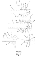
- FIG. 1 different views of a prior art coupling member 2 between a sound tube 6 for a hearing aid device and a hearing aid dome 4 is illustrated in Fig. 1 .
- Fig. 1a is a schematic cross-sectional view of a prior art coupling member 2.
- the coupling member 2 comprises a sound tube 6 having a distal end 34 to which an elongated sleeve 18 is attached.
- the elongated sleeve 18 constitutes a male member 28 that is attached to a female member 30 formed as a hearing aid dome 4.
- the elongated sleeve 18 has a first annular rib 8, a second annular rib 8' and a third annular rib 8".
- Fig. 1b it can be seen that all the three annular ribs 8, 8', 8" have the same height H 1 relative to the first base surface 14 of the sound tube 6. It can also be seen that the annular ribs 8, 8', 8" have the same shape and that each of them comprise a plane surface 12 and an angled or tapered surface 10. A plane surface 16 is provided between each pair of adjacent ribs 8, 8', 8".
- the female member 30 is formed as a hearing aid dome 4 and comprises three cavities 20 that are configured to receive the three annular ribs 8, 8', 8". The cavities 20 each have a plane surface 24 and a concave surface 22.
- the hearing aid dome 4 has a stop member 26 adapted to restrict further movement of the elongated sleeve 18 when it has entered the end portion of the hearing aid dome 4 and bears against the stop member 26.
- the cavities 20 each comprise a plane surface 24 configured to receive the corresponding plane surface 12 of the corresponding annular ribs 8, 8', 8".
- a problem that typically arises when using a prior art coupling member 2, as the one shown in Fig. 1 is, that only some of the annular ribs 8, 8', 8" are inserted into the hearing aid dome 4 (like illustrated in Fig. 1 b ) - accordingly, the distal end 34 of the sound tube 6 has not been properly inserted into the hearing aid dome 4.
- the hearing aid dome 4 gets stuck in the ear canal of the user, when the user of the hearing aid pulls the sound tube 6 in order to remove the hearing aid dome 4 from the ear canal. Therefore, it is a significant problem of the prior art that the hearing aid dome 4 can get stuck in the ear canal of the user.
- annular ribs 8, 8', 8" are subject to substantial wear that causes erosion of the annular ribs 8, 8', 8".
- This is illustrated in Fig. 1 c) and in the corresponding close-up view Fig. 1 d) .
- the annular ribs 8, 8', 8" in Fig. 1 c) and 1 d ) have a more "round off” geometry compared with the annular ribs 8, 8', 8" in Fig. 1 a) and 1 b ).
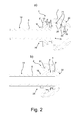
- Fig. 2 illustrates a cross-sectional view of a coupling member 2 according to the invention.
- the coupling member 2 is used to join a sound tube 6 for a hearing aid and a hearing aid dome 4 according to the invention.
- the sound tube 6, has an outer surface 14.
- an elongated sleeve 18 is attached.
- the elongated sleeve 18 comprises a first annular rib 8, a second annular rib 8' and a third annular rib 8" and constitutes a male member.
- a close-up cross-sectional view is shown in Fig.
- each annular rib 8, 8', 8" comprises a plane surface 12 and an angled or tapered surface 10.
- the hearing aid dome 4 constitutes a female member 30 having three cavities 20 each comprising a concave surface 22, a side wall 23 and a plane surface 24.
- the female member 30 is shaped as a hearing aid dome 4 having three cavities 20 configured to receive the annular rib 8, 8', 8" of the elongated sleeve 18.
- the stop member 26 as well as the side walls 23 of the cavities 20, prevent the elongated sleeve 18 from being entered further into the dome 4.
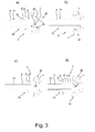
- Fig. 3 a) and Fig. 3 b) illustrate cross-sectional views of another embodiment of a coupling member 2 according to the invention.
- the coupling member 2 comprises a sound tube 6 having an outer surface 14.
- an elongated sleeve 18 is attached at the distal end 34 of the sound tube 6 .
- the elongated sleeve 18 comprises a first annular rib 8, a second annular rib 8' and a third annular rib 8".
- the elongated sleeve 18 constitutes a male member 28 and the profile of the annular ribs 8, 8', 8" are saw-tooth shaped.
- the coupling member 2 also comprises a hearing aid dome 4 that constitutes a female member 30 provided with three cavities 20 corresponding to the geometry of the annular ribs 8, 8', 8".
- the three cavities 20 are configured to receive the annular rib 8, 8', 8" of the elongated sleeve 18.
- the dome 4 comprises a stop member 26 as well as side walls 23 of each of the cavities 20. The stop member 26 and the side walls 23 prevent the elongated sleeve 18 from being entered further into the dome 4.
- the dome 4 and the sound tube 6 are separated in Fig. 3 a) and joined in Fig. 3 b) .
- Fig. 3 c) illustrates a cross-sectional view of one embodiment of a coupling member 2 according to the invention.
- the coupling member 2 basically corresponds to the coupling member 2 shown in Fig. 3 a) and 3 b), however; the sound tube 6 has an elongated sleeve 18 that comprises only two annular ribs 8, 8' (a first annular rib 8 and a second annular rib 8') that are saw-tooth shaped.
- the elongated sleeve 18 and the sound tube 6 are integrated into a one-piece body.
- Fig. 3 d illustrates a cross-sectional view of an alternative embodiment of a coupling member 2 according to the invention.
- the coupling member 2 has a sound tube 6 provided with an elongated sleeve 18 that comprises a first annular rib 8, a second annular rib 8', third annular rib 8" and a fourth annular rib 8"'.
- the annular ribs 8, 8', 8", 8''' are saw-tooth shaped, however wear has rounded-off the annular ribs 8, 8', 8", 8'''.
- the elongated sleeve 18 and the sound tube 6 are integrated into a one-piece body.
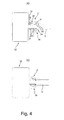
- Fig. 4 a illustrates a cross-sectional view of another embodiment of a coupling member 2 according to the invention.
- the coupling member 2 comprises a sound tube 6' provided with a female member 30 basically corresponding to the female member 30 illustrated in Fig. 2 .
- a male member 28 is attached to a sound tube 6 that is connected to a hearing aid casing 32.
- An elongated sleeve 18 that comprises a first annular rib 8, a second annular rib 8' and a third annular rib 8" is attached to the sound tube 6. It can be seen that the height of the annular ribs 8, 8', 8" increases as function of the distance from the annular ribs 8, 8', 8" to the distal end 34 of the sound tube 6. The distance is measured from the distal end 34 of the sound tube 6 to place at which the annular ribs 8, 8', 8" are arranged.
- Fig. 5 a illustrates a close-up view of the elongated sleeve 18 shown in Fig. 2 and in Fig. 4 .
- the elongated sleeve 18 is attached to a sound tube 6 and the elongated sleeve 18 comprises a first annular rib 8, a second annular rib 8' and a third annular rib 8".
- the height H 1 , H 2 , H 3 of the annular ribs 8, 8', 8" increases as function of the distance from the distal end 34 of the sound tube 6.
- the height H 1 , H 2 , H 3 of the annular ribs 8, 8', 8" are measured from the outer surface 14 of the sound tube.
- the first annular rib 8 is arranged closest to the distal end 34 of the sound tube 6. In fact the first annular rib 8 is arranged at the distal end 34 of the sound tube 6 and thus the height H 1 of the first annular rib 8 is smaller than the height H 2 of the second annular rib 8' that is arranged in a first non-zero distance d 1 to the to the distal end 34 of the sound tube 6.
- the third annular rib 8" is arranged in a second non-zero distance d 2 from the distal end 34 of the sound tube 6. Since the second distance d 2 is larger than the first distance d 1 from the distal end 34 of the sound tube 6, the height H 3 of the third annular rib 8" is larger than the height H 2 of the second annular rib 8'.
- the width W 1 of the first annular rib 8 corresponds to the width W 2 of the second annular rib 8' and to the width W 3 of the third annular rib 8".
- Fig. 5 b illustrates a clos-up view of an elongated sleeve 18 attached to a sound tube 6.
- the elongated sleeve 18 comprises a first annular rib 8, a second annular rib 8', a third annular rib 8" and a fourth annular rib 8"'.
- the height H 1 , H 2 , H 3 , H 4 of each of the annular ribs 8, 8', 8", 8''' increases as function of the distance from the ribs 8, 8', 8", 8''' to the distal end 34 of the sound tube 6.
Landscapes
- Engineering & Computer Science (AREA)
- Manufacturing & Machinery (AREA)
- Health & Medical Sciences (AREA)
- General Health & Medical Sciences (AREA)
- Neurosurgery (AREA)
- Otolaryngology (AREA)
- Physics & Mathematics (AREA)
- Acoustics & Sound (AREA)
- Signal Processing (AREA)
- Quick-Acting Or Multi-Walled Pipe Joints (AREA)
- Details Of Connecting Devices For Male And Female Coupling (AREA)
Abstract
Description
- The present invention generally relates to a coupling member for a hearing system, such as a hearing aid device or a hearing diagnosis device. The present invention more particularly relates a coupling member for joining a male member and a female member, where the male member comprises two or more annular ribs extending radially from a pipe member having a distal end, where the female member comprises a number of cavities configured to receive and contain the annular ribs of the male member.
- Today several hearing aids have been developed to correct the hearing of users having different degrees of hearing impairments. A traditional approach to correct hearing impairments is to employ a behind-the-ear (BTE) hearing aid device attached behind the ear or a receiver-in-the-ear (RITE) hearing aid device. The BTE hearing aid devices typically comprise a flexible plastic tube that connects a BTE hearing aid device to a dome that is configured to be placed within the ear. A RITE hearing aid device typically comprises a flexible plastic tube that connects a BTE hearing aid device to a small speaker to which a dome is attached.
- The domes used for these purposes normally comprise a number of cavities adapted to receive a male member having a corresponding number (typically three) of radially extending annular ribs. The male member is normally an integrated portion of the speaker (in a RITE hearing aid device) or a sleeve member attached to the distal end of a flexible sound tube (in a BTE hearing aid device).
- A dome of this kind occasionally needs to be cleaned by the user of the hearing aid device or to be changed in case of wear. A significant risk that is present during replacement of a dome is the risk of an incomplete mounting of the male member in the cavities of the dome. The problem is that some of the annular ribs of the male member may not be attached to the cavities of the dome. Hereby the strength of the attachment between the male member and the dome is significantly reduced since optimum strength of attachment requires that all the annular ribs of the male member are received by corresponding cavities of the dome.
- The dome and the male member configured to be inserted into the dome are subject to wear each time the dome is attached to a male member and each time the dome is unattached from a male member. Wear caused by attaching the dome to a male member or caused by unattaching the dome from a male member reduces the strength of the attachment between the male member and the dome.
- Accordingly, in case of incomplete mounting of the male member in the cavities of the dome or in case of wear of the dome or the male member, there is a risk that the dome remains in the ear canal when the user of a BTE hearing aid device attempts to remove the dome from the ear by pulling the flexible plastic tube connecting a BTE hearing aid device to the dome. In the same manner the dome may get stuck in the ear canal when the user of a RITE hearing aid device attempts to remove the male member of the speaker from the dome by pulling the sound tube that is connected to the remaining part of the hearing aid device.
- Thus, there is a need for a coupling member that reduces or even eliminates the above mentioned disadvantages of the prior art.
- It is an object of the present invention to provide a coupling member that is subject to less wear during use. Moreover, is an object of the present invention to provide an improved coupling member that provides a stronger coupling between the dome and the male member of the tube or between the dome and the male member of the speaker.
- The object of the present invention can be achieved by a coupling member as defined in
claim 1. Preferred embodiments are defined in the dependent sub claims and explained in the following description and illustrated in the accompanying drawings. - The coupling member according to the invention is a coupling member for joining a male member and a female member of a hearing aid device or a hearing diagnosis device, where the male member comprises two or more annular ribs extending radially from a pipe member having a distal end, where the female member comprises a number of cavities configured to receive and contain the annular ribs of the male member. The height of the annular ribs increases as function of the distance from the annular ribs to the distal end of the pipe member.
- Hereby a better and stronger coupling between the dome and the male member is achieved. Moreover, the coupling member is subject to less wear during use.
- The distance rom the annular ribs to the distal end of the pipe member equals the distance from the distal end of the pipe member to the place at which the annular ribs are arranged.
- The pipe member may be a sound tube or any other type of pipe structure in a hearing aid device or a hearing diagnosis device, e.g. a speaker of a RITE hearing aid device having a canal, through which the sound from the speaker is transmitted.
- By the term joining is meant a mechanical attachment e.g. based on the principle of interlocking.
- The hearing aid device may in principle be any type of hearing aid device in which the coupling member according to the invention is suitable. The coupling may also be used in a hearing diagnosis device.
- The annular ribs are extending radially from a pipe member such that the annular ribs extend basically perpendicular to the pipe member. It is essential that the annular ribs are capable of constituting interlocking means when received by the corresponding cavities of the female member.
- The distal end of the pipe member refers to the free end in which annular ribs are provided.
- The cavities have such a geometry that they can receive and contain the annular ribs of the male member and hereby provide the required interlocking.
- When the height of the annular ribs increases as function of the distance from the annular ribs to the distal end of the pipe member, it means that the annular rib that is arranged closest to the distal end of the pipe member has the smallest height. Moreover, any second annular rib arranged in a larger distance to the distal end of the pipe member than a first annular rib has a larger height than the first annular rib. The annular rib that is arranged adjacent to the annular rib closest to the distal end of the pipe member is higher than the annular rib closest to the distal end of the pipe member.
- The height of an annular rib may be measured as the shortest distance from the top of the annular rib to the outer surface of the pipe member onto which the annular rib is provided/arranged.
- It is preferred that the male member comprises an elongated sleeve extending parallel to the pipe member and being attached to the pipe member, where the two or more annular ribs are attached to the sleeve.
- Hereby it is possible to provide a reliable attachment of a pipe member (e.g. a sound tube) to a female member by attaching the elongated sleeve to the pipe member.
- It may be an advantage that the male member comprises an elongated sleeve extending parallel to the pipe member and being attached to the pipe member, where the two or more annular ribs are an integrated part of the sleeve.
- Hereby it is ensured that the pipe member is capable of taking up the forces from the female member through the elongated sleeve without causing separation of the elongated sleeve and the pipe member. Hence a very strong and reliable solution can be achieved.
- It may be beneficial that the pipe member has a cylindrical geometry and a circular cross-sectional area, and that the sleeve comprises a cylindrical portion configured to be arranged around the pipe member.
- Hereby the sleeve can be attached to standard sound tubes.
- It may be an advantage that the male member comprises three annular ribs having basically the same width.
- It may be an advantage that the elongated sleeve is a separate body that is attached to the pipe member.
- It may be preferred that the height of the annular ribs depends linear of the distance from the annular ribs to the distal end of the pipe member.
- Hereby a simplified and reliable coupling member can be provided and further the construction of the corresponding cavities of the female member may be eased.
- It is preferred that the male member and the female member are configured to be joined by pressing the male member into the female member by a single smooth movement of male member towards the female member without interruption.
- Hereby a "one click" attachment procedure is achieved. This is a major advantage compared with the prior art coupling members.
- It may be an advantage that the widths of the annular ribs correspond to the widths of the surface between annular ribs.
- Hereby a strong and compact coupling member can be achieved.
- It is preferred that the female member is made in a resilient material, preferably a soft silicone material, or that the annular ribs are made in a resilient material, preferably a soft silicone material.
- Hereby, joining of the male member and the female member is eased.
- It is preferred that the annular ribs have a saw-tooth profile or a profile with a plane surface and a curved surface.
- Hereby a firm attachment can be achieved by interlocking.
- It may be an advantage that the female member is a dome, preferably an open dome or a closed dome or a power dome or a double dome or a triple dome or a plus dome, since these domes are frequently used domes.
- It may be an advantage that the female member is a disposable ear-tip configured to be arranged on the hearing aid's speaker unit in order to give a comfortable fit in the ear.
- It is preferred that the pipe member is a sound tube of a hearing aid device or a hearing diagnosis device.
- It may be an advantage that the sound tube is a flexible tube such as a thin tube.
- The hearing system according to the invention is a hearing aid device or a hearing diagnosis device comprising a coupling member according to the invention.
- It is preferred that the hearing aid device is a BTE hearing aid device or a RITE hearing aid device.
- In the present context, a "hearing aid device" refers to a device, such as e.g. a hearing aid, a listening device or an active ear-protection device, which is adapted to improve, augment and/or protect the hearing capability of a user by receiving acoustic signals from the user's surroundings, generating corresponding audio signals, possibly modifying the audio signals and providing the possibly modified audio signals as audible signals to at least one of the user's ears.
- A hearing aid device may be configured to be worn in any known way, e.g. as a unit arranged behind the ear with a tube leading air-borne acoustic signals into the ear canal or with a loudspeaker arranged close to or in the ear canal.
- A hearing aid device may comprise a single unit or several units communicating electronically with each other. More generally, a hearing aid device comprises an input transducer for receiving an acoustic signal from a user's surroundings and providing a corresponding input audio signal and/or a receiver for electronically receiving an input audio signal, a signal processing circuit for processing the input audio signal and an output means for providing an audible signal to the user in dependence on the processed audio signal. Some hearing aid devices may comprise multiple input transducers, e.g. for providing direction-dependent audio signal processing. In some hearing aid devices, the receiver may be a wireless receiver.
- In some hearing aid devices, the receiver may be e.g. an input amplifier for receiving a wired signal. In some hearing aid devices, an amplifier may constitute the signal processing circuit. In some hearing aid devices, the output means may comprise an output transducer, such as e.g. a loudspeaker for providing an air-borne acoustic signal.
- The invention will become more fully understood from the detailed description given herein below. The accompanying drawings are given by way of illustration only, and thus, they are not limitative of the present invention. In the accompanying drawings:
- Fig. 1
- shows different views of a prior art coupling member between a sound tube for a hearing aid device and a hearing aid dome;
- Fig. 2
- shows two different views of a coupling member between a sound tube for a hearing aid device and a hearing aid dome according to the invention;
- Fig. 3
- shows three different coupling members according to the invention;
- Fig. 4
- shows a cross-sectional view of another coupling member according to the invention and
- Fig. 5
- shows a close-up cross-sectional view of two coupling members according to the invention.
- Referring now to the drawings for illustrating embodiments of the invention, different views of a prior
art coupling member 2 between asound tube 6 for a hearing aid device and ahearing aid dome 4 is illustrated inFig. 1 . -
Fig. 1a ) is a schematic cross-sectional view of a priorart coupling member 2. Thecoupling member 2 comprises asound tube 6 having adistal end 34 to which anelongated sleeve 18 is attached. Theelongated sleeve 18 constitutes amale member 28 that is attached to afemale member 30 formed as ahearing aid dome 4. Theelongated sleeve 18 has a firstannular rib 8, a second annular rib 8' and a thirdannular rib 8". - In
Fig. 1b ) it can be seen that all the threeannular ribs first base surface 14 of thesound tube 6. It can also be seen that theannular ribs surface 10. Aplane surface 16 is provided between each pair ofadjacent ribs female member 30 is formed as ahearing aid dome 4 and comprises threecavities 20 that are configured to receive the threeannular ribs cavities 20 each have aplane surface 24 and aconcave surface 22. - Moreover, the
hearing aid dome 4 has astop member 26 adapted to restrict further movement of theelongated sleeve 18 when it has entered the end portion of thehearing aid dome 4 and bears against thestop member 26. Thecavities 20 each comprise aplane surface 24 configured to receive the corresponding plane surface 12 of the correspondingannular ribs - A problem that typically arises when using a prior
art coupling member 2, as the one shown inFig. 1 is, that only some of theannular ribs Fig. 1 b ) - accordingly, thedistal end 34 of thesound tube 6 has not been properly inserted into thehearing aid dome 4. When this occurs, there is a risk that thehearing aid dome 4 gets stuck in the ear canal of the user, when the user of the hearing aid pulls thesound tube 6 in order to remove thehearing aid dome 4 from the ear canal. Therefore, it is a significant problem of the prior art that thehearing aid dome 4 can get stuck in the ear canal of the user. - Moreover, as time goes by the
annular ribs annular ribs Fig. 1 c) and in the corresponding close-up viewFig. 1 d) . It can be seen that theannular ribs Fig. 1 c) and 1 d ) have a more "round off" geometry compared with theannular ribs Fig. 1 a) and 1 b ). This means that the interlocking coupling between thesound tube 6 and thehearing aid dome 4 becomes weaker and weaker as theannular ribs dome 4, especially at thesurfaces 21, 24 (not shown inFig. 1 ). -
Fig. 2 illustrates a cross-sectional view of acoupling member 2 according to the invention. Thecoupling member 2 is used to join asound tube 6 for a hearing aid and ahearing aid dome 4 according to the invention. Thesound tube 6, has anouter surface 14. At thedistal end 34 of thetube 6 anelongated sleeve 18 is attached. Theelongated sleeve 18 comprises a firstannular rib 8, a second annular rib 8' and a thirdannular rib 8" and constitutes a male member. A close-up cross-sectional view is shown inFig. 5 a) , and here the height H1 of the firstannular rib 8 is smaller than the height H2 of the second annular rib 8' and that the height H3 of the a thirdannular rib 8" is larger than the height H2 of the a second annular rib 8'. Eachannular rib surface 10. - The
hearing aid dome 4 constitutes afemale member 30 having threecavities 20 each comprising aconcave surface 22, aside wall 23 and aplane surface 24. Thefemale member 30 is shaped as ahearing aid dome 4 having threecavities 20 configured to receive theannular rib elongated sleeve 18. Thestop member 26 as well as theside walls 23 of thecavities 20, prevent theelongated sleeve 18 from being entered further into thedome 4. - In
Fig. 2 b) theelongated sleeve 18 of thesound tube 6 has been joined with thehearing aid dome 4. By using the illustratedcoupling member 2 according to the invention it is possible to provide a secure coupling of thesound tube 6 and thehearing aid dome 4 by pressing together thesound tube 6 and the hearing aid dome in one smooth movement, where theannular ribs cavities 20 of thedome 4. -
Fig. 3 a) and Fig. 3 b) illustrate cross-sectional views of another embodiment of acoupling member 2 according to the invention. Thecoupling member 2 comprises asound tube 6 having anouter surface 14. At thedistal end 34 of thesound tube 6 anelongated sleeve 18 is attached. Theelongated sleeve 18 comprises a firstannular rib 8, a second annular rib 8' and a thirdannular rib 8". Theelongated sleeve 18 constitutes amale member 28 and the profile of theannular ribs - The
coupling member 2 also comprises ahearing aid dome 4 that constitutes afemale member 30 provided with threecavities 20 corresponding to the geometry of theannular ribs cavities 20 are configured to receive theannular rib elongated sleeve 18. Thedome 4 comprises astop member 26 as well asside walls 23 of each of thecavities 20. Thestop member 26 and theside walls 23 prevent theelongated sleeve 18 from being entered further into thedome 4. - The
dome 4 and thesound tube 6 are separated inFig. 3 a) and joined inFig. 3 b) . -
Fig. 3 c) illustrates a cross-sectional view of one embodiment of acoupling member 2 according to the invention. Thecoupling member 2 basically corresponds to thecoupling member 2 shown inFig. 3 a) and 3 b), however; thesound tube 6 has an elongatedsleeve 18 that comprises only twoannular ribs 8, 8' (a firstannular rib 8 and a second annular rib 8') that are saw-tooth shaped. Theelongated sleeve 18 and thesound tube 6 are integrated into a one-piece body. -
Fig. 3 d) on the other hand illustrates a cross-sectional view of an alternative embodiment of acoupling member 2 according to the invention. Thecoupling member 2 has asound tube 6 provided with anelongated sleeve 18 that comprises a firstannular rib 8, a second annular rib 8', thirdannular rib 8" and a fourthannular rib 8"'. Theannular ribs annular ribs elongated sleeve 18 and thesound tube 6 are integrated into a one-piece body. -
Fig. 4 a) illustrates a cross-sectional view of another embodiment of acoupling member 2 according to the invention. Thecoupling member 2 comprises a sound tube 6' provided with afemale member 30 basically corresponding to thefemale member 30 illustrated inFig. 2 . Amale member 28 is attached to asound tube 6 that is connected to ahearing aid casing 32. Anelongated sleeve 18 that comprises a firstannular rib 8, a second annular rib 8' and a thirdannular rib 8" is attached to thesound tube 6. It can be seen that the height of theannular ribs annular ribs distal end 34 of thesound tube 6. The distance is measured from thedistal end 34 of thesound tube 6 to place at which theannular ribs - In
Fig. 4 b) thefemale member 30 of the sound tube 6' and themale member 28 of thesound tube 6 connected to thehearing aid case 32 are joined. It can be seen that theannular ribs cavities 20 of thefemale member 30. -
Fig. 5 a) illustrates a close-up view of theelongated sleeve 18 shown inFig. 2 and inFig. 4 . Theelongated sleeve 18 is attached to asound tube 6 and theelongated sleeve 18 comprises a firstannular rib 8, a second annular rib 8' and a thirdannular rib 8". The height H1, H2, H3 of theannular ribs distal end 34 of thesound tube 6. The height H1, H2, H3 of theannular ribs outer surface 14 of the sound tube. - The first
annular rib 8 is arranged closest to thedistal end 34 of thesound tube 6. In fact the firstannular rib 8 is arranged at thedistal end 34 of thesound tube 6 and thus the height H1 of the firstannular rib 8 is smaller than the height H2 of the second annular rib 8' that is arranged in a first non-zero distance d1 to the to thedistal end 34 of thesound tube 6. The thirdannular rib 8" is arranged in a second non-zero distance d2 from thedistal end 34 of thesound tube 6. Since the second distance d2 is larger than the first distance d1 from thedistal end 34 of thesound tube 6, the height H3 of the thirdannular rib 8" is larger than the height H2 of the second annular rib 8'. - The width W1 of the first
annular rib 8 corresponds to the width W2 of the second annular rib 8' and to the width W3 of the thirdannular rib 8". Theplane surface 16 between the firstannular rib 8 and the second annular rib 8' has a width C1 that corresponds to the width C2 of theplane surface 16 between the second annular rib 8' and the thirdannular rib 8". It can be seen that
and that
-
Fig. 5 b) illustrates a clos-up view of anelongated sleeve 18 attached to asound tube 6. Theelongated sleeve 18 comprises a firstannular rib 8, a second annular rib 8', a thirdannular rib 8" and a fourthannular rib 8"'. The height H1, H2, H3, H4 of each of theannular ribs outer surface 14 of the sound tube) increases as function of the distance from theribs distal end 34 of thesound tube 6. -
- 2 -
- Coupling member
- 4 -
- Dome
- 6, 6' -
- Tube
- 8, 8, 8', 8" -
- Annular rib
- 10 -
- Angled or tapered surface
- 12 -
- Plane surface
- 14 -
- Surface
- 16 -
- Surface
- 18 -
- Elongated sleeve
- 20 -
- Cavity
- 21 -
- Surface
- 22 -
- Concave surface
- 23 -
- Side wall
- 24 -
- Plane surface
- 26 -
- Stop member
- 28 -
- Male member
- 30 -
- Female member
- 32 -
- Hearing aid case
- 34 -
- Distal end
- H1, H2, H3, H4 -
- Height
- W1, W2, W3 -
- Width
- C1, C2 -
- Width
- d1, d2 -
- Distance
Claims (15)
- A coupling member (2) for joining a male member (28) and a female member (30) of a hearing aid device or a hearing diagnosis device, where the male member (28) comprises two or more annular ribs (8, 8', 8", 8"') extending radially from a pipe member (6) having a distal end (34), where the female member (30) comprises a number of cavities (20) configured to receive and contain the annular ribs (8, 8', 8", 8''') of the male member (28) characterised in that the height (H1, H2, H3, H4) of the annular ribs (8, 8', 8", 8''') increases as function of the distance (d1, d2) from the annular ribs (8, 8', 8", 8''') to the distal end (34) of the pipe member (6).
- A coupling member (2) according to claim 1 characterised in that the male member (28) comprises an elongated sleeve (18) extending parallel to the pipe member (6) and being attached to the pipe member (6), where the two or more annular ribs (8, 8', 8", 8''') are attached to the sleeve (18).
- A coupling member (2) according to claim 1 characterised in that the male member (28) comprises an elongated sleeve (18) extending parallel to the pipe member (6) and being attached to the pipe member (6), where the two or more annular ribs (8, 8', 8", 8''') are an integrated part of the sleeve (18).
- A coupling member (2) according to claim 2 or claim 3 characterised in that the pipe member (6) has a cylindrical geometry and a circular cross-sectional area, and that the sleeve (18) comprises a cylindrical portion configured to be arranged around the pipe member (6).
- A coupling member (2) according to one of the preceding claims characterised in that the male member (28) comprises three annular ribs (8, 8', 8") having basically the same width (W1, W2, W3).
- A coupling member (2) according to one of the preceding claims characterised in that the height (H1, H2, H3, H4) of the annular ribs (8, 8', 8", 8"') depends linear of the distance (d1, d2) from the annular ribs (8, 8', 8", 8''') to the distal end (34) of the pipe member (6).
- A coupling member (2) according to one of the preceding claims characterised in that the male member (28) and the female member (30) are configured to be joined by pressing the male member (28) into the female member (30) by a single smooth movement of male member (28) towards the female member (30) without interruption.
- A coupling member (2) according to one of the preceding claims characterised in that the widths (W1, W2, W3) of the annular ribs (8, 8', 8", 8''') correspond to the widths (C1, C2) of the surface (16) between annular ribs (8, 8', 8", 8''').
- A coupling member (2) according to one of the preceding claims characterised in that the female member (30) is made in a resilient material, preferably a soft silicone material, or that the annular ribs (8, 8', 8", 8''') are made in a resilient material, preferably a soft silicone material.
- A coupling member (2) according to one of the preceding claims characterised in that the annular ribs (8, 8', 8", 8"') have a saw-tooth profile or a profile with a plane surface (12) and a curved surface (10).
- A coupling member (2) according to one of the preceding claims characterised in that the female member (30) is adapted for placement in the ear canal of a hearing aid user, and comprises a dome (4), preferably an open dome (4) or a closed dome (4) or a power dome (4) or a double dome (4) or a triple dome (4).
- A coupling member (2) according to one of the preceding claims characterised in that the pipe member (6) is a sound tube (6) of a hearing aid device or a hearing diagnostic device.
- A coupling member (2) according to claim 12 characterised in that the sound tube (6) is a flexible tube (6).
- A hearing aid device or a hearing diagnosis device comprising a coupling member (2) according to one of the preceding claims
- A hearing aid device according to claim 14 characterised in that the hearing aid device is a behind-the-ear (BTE) hearing aid device or a receiver-in-the-ear (RITE) hearing aid device.
Priority Applications (3)
| Application Number | Priority Date | Filing Date | Title |
|---|---|---|---|
| EP13175543.1A EP2824939A1 (en) | 2013-07-08 | 2013-07-08 | Coupling member and hearing system using it |
| US14/324,584 US9392383B2 (en) | 2013-07-08 | 2014-07-07 | Coupling member and hearing system using it |
| CN201410324594.1A CN104284287A (en) | 2013-07-08 | 2014-07-08 | Coupling member and hearing system using it |
Applications Claiming Priority (1)
| Application Number | Priority Date | Filing Date | Title |
|---|---|---|---|
| EP13175543.1A EP2824939A1 (en) | 2013-07-08 | 2013-07-08 | Coupling member and hearing system using it |
Publications (1)
| Publication Number | Publication Date |
|---|---|
| EP2824939A1 true EP2824939A1 (en) | 2015-01-14 |
Family
ID=48746367
Family Applications (1)
| Application Number | Title | Priority Date | Filing Date |
|---|---|---|---|
| EP13175543.1A Withdrawn EP2824939A1 (en) | 2013-07-08 | 2013-07-08 | Coupling member and hearing system using it |
Country Status (3)
| Country | Link |
|---|---|
| US (1) | US9392383B2 (en) |
| EP (1) | EP2824939A1 (en) |
| CN (1) | CN104284287A (en) |
Families Citing this family (2)
| Publication number | Priority date | Publication date | Assignee | Title |
|---|---|---|---|---|
| CN209002220U (en) * | 2015-05-27 | 2019-06-18 | 西万拓私人有限公司 | Hearing device with plug connection for earpieces |
| US20240073575A1 (en) * | 2022-08-25 | 2024-02-29 | David Clark Company Incorporated | Intra-aural earbud |
Citations (2)
| Publication number | Priority date | Publication date | Assignee | Title |
|---|---|---|---|---|
| US5488205A (en) * | 1993-09-01 | 1996-01-30 | Microsonic, Inc. | Hearing aid tubing connector |
| US20090041261A1 (en) * | 2007-08-06 | 2009-02-12 | Siemens Medical Instruments Pte. Ltd. | Receiver facility with an elastically mounted receiver |
Family Cites Families (10)
| Publication number | Priority date | Publication date | Assignee | Title |
|---|---|---|---|---|
| US3907342A (en) * | 1973-08-27 | 1975-09-23 | Thor Power Tool Co | Barb means for a hose connector |
| US4511163A (en) * | 1982-07-14 | 1985-04-16 | Mead Johnson & Company | Adaptable tip tubing connector |
| US4597594A (en) * | 1983-09-09 | 1986-07-01 | Chris Kaye Plastics Corp. | Hose connector |
| US5449865A (en) * | 1994-01-28 | 1995-09-12 | Minnesota Mining And Manufacturing Company | Ear tips having molded-in recesses for attachment to a stethoscope |
| DE69836635T2 (en) * | 1997-07-18 | 2007-09-27 | Resound Corp., Redwood City | BEHIND-THE-EAR hearing aid |
| WO2007147049A2 (en) * | 2006-06-14 | 2007-12-21 | Think-A-Move, Ltd. | Ear sensor assembly for speech processing |
| US7856111B2 (en) * | 2006-10-04 | 2010-12-21 | Siemens Audiologische Technik Gmbh | Hearing aid with sound tube serving for retention in concha |
| US8101103B2 (en) * | 2007-02-06 | 2012-01-24 | Honeywell International Inc. | Earbud and method of manufacture |
| DE102007014131A1 (en) * | 2007-03-23 | 2008-09-25 | Siemens Audiologische Technik Gmbh | Hearing aid with a fastening of a receiver tube |
| US8116495B2 (en) * | 2008-03-31 | 2012-02-14 | Starkey Laboratories, Inc. | Reinforced earbud device, system and method |
-
2013
- 2013-07-08 EP EP13175543.1A patent/EP2824939A1/en not_active Withdrawn
-
2014
- 2014-07-07 US US14/324,584 patent/US9392383B2/en not_active Expired - Fee Related
- 2014-07-08 CN CN201410324594.1A patent/CN104284287A/en active Pending
Patent Citations (2)
| Publication number | Priority date | Publication date | Assignee | Title |
|---|---|---|---|---|
| US5488205A (en) * | 1993-09-01 | 1996-01-30 | Microsonic, Inc. | Hearing aid tubing connector |
| US20090041261A1 (en) * | 2007-08-06 | 2009-02-12 | Siemens Medical Instruments Pte. Ltd. | Receiver facility with an elastically mounted receiver |
Also Published As
| Publication number | Publication date |
|---|---|
| CN104284287A (en) | 2015-01-14 |
| US9392383B2 (en) | 2016-07-12 |
| US20150010184A1 (en) | 2015-01-08 |
Similar Documents
| Publication | Publication Date | Title |
|---|---|---|
| CN102158790B (en) | Hearing aid with removable attached earpiece | |
| US8774434B2 (en) | Self-adjustable and deforming hearing device | |
| US9025807B2 (en) | Couplable hearing apparatus for a hearing device, coupling element and hearing device | |
| EP2601795B1 (en) | Receiver system for a hearing instrument | |
| US5875254A (en) | Binaural hearing aid with integrated retrieval line and microphone | |
| US8175308B2 (en) | Earplug for a hearing aid | |
| JP5150798B1 (en) | Hearing aid earplugs and hearing aids | |
| US20110188690A1 (en) | Receiver in concha | |
| AU8287998A (en) | Acoustic coupler | |
| US10440485B2 (en) | Hearing aid and earpiece | |
| KR101748168B1 (en) | Bearing aids with dual microphone for easy-detachment of shell and silicon sleeve tip | |
| US9860651B2 (en) | Behind the ear hearing aid | |
| EP2824939A1 (en) | Coupling member and hearing system using it | |
| JP2008541676A (en) | Hearing aid hook | |
| KR101777182B1 (en) | hearing aids without resonance phenomenon for easy-detachment of shell and silicon sleeve tip | |
| US8311251B2 (en) | Electronic apparatus for connection to a hearing apparatus component with a two-part sleeve | |
| CN113207072B (en) | Assembly comprising a sensor in a nozzle | |
| CN101180918A (en) | Hooks for hearing aids | |
| KR101748167B1 (en) | Hearing aid with microphone attached in handle for hearing | |
| EP2595413A1 (en) | Docking station for hearing aids | |
| KR101775501B1 (en) | hearing aids and earphone without resonance phenomenon | |
| EP3484171A1 (en) | An assembly for a personal audio device |
Legal Events
| Date | Code | Title | Description |
|---|---|---|---|
| 17P | Request for examination filed |
Effective date: 20130708 |
|
| AK | Designated contracting states |
Kind code of ref document: A1 Designated state(s): AL AT BE BG CH CY CZ DE DK EE ES FI FR GB GR HR HU IE IS IT LI LT LU LV MC MK MT NL NO PL PT RO RS SE SI SK SM TR |
|
| AX | Request for extension of the european patent |
Extension state: BA ME |
|
| PUAI | Public reference made under article 153(3) epc to a published international application that has entered the european phase |
Free format text: ORIGINAL CODE: 0009012 |
|
| R17P | Request for examination filed (corrected) |
Effective date: 20150714 |
|
| RBV | Designated contracting states (corrected) |
Designated state(s): AL AT BE BG CH CY CZ DE DK EE ES FI FR GB GR HR HU IE IS IT LI LT LU LV MC MK MT NL NO PL PT RO RS SE SI SK SM TR |
|
| 17Q | First examination report despatched |
Effective date: 20161018 |
|
| STAA | Information on the status of an ep patent application or granted ep patent |
Free format text: STATUS: THE APPLICATION IS DEEMED TO BE WITHDRAWN |
|
| 18D | Application deemed to be withdrawn |
Effective date: 20180327 |