EP2824886B1 - Path computation element communication protocol session establishment method and device - Google Patents
Path computation element communication protocol session establishment method and device Download PDFInfo
- Publication number
- EP2824886B1 EP2824886B1 EP13775429.7A EP13775429A EP2824886B1 EP 2824886 B1 EP2824886 B1 EP 2824886B1 EP 13775429 A EP13775429 A EP 13775429A EP 2824886 B1 EP2824886 B1 EP 2824886B1
- Authority
- EP
- European Patent Office
- Prior art keywords
- pce
- pcc
- pcep
- client
- session
- Prior art date
- Legal status (The legal status is an assumption and is not a legal conclusion. Google has not performed a legal analysis and makes no representation as to the accuracy of the status listed.)
- Active
Links
Images


Classifications
-
- H—ELECTRICITY
- H04—ELECTRIC COMMUNICATION TECHNIQUE
- H04L—TRANSMISSION OF DIGITAL INFORMATION, e.g. TELEGRAPHIC COMMUNICATION
- H04L67/00—Network arrangements or protocols for supporting network services or applications
- H04L67/14—Session management
- H04L67/141—Setup of application sessions
-
- H—ELECTRICITY
- H04—ELECTRIC COMMUNICATION TECHNIQUE
- H04L—TRANSMISSION OF DIGITAL INFORMATION, e.g. TELEGRAPHIC COMMUNICATION
- H04L45/00—Routing or path finding of packets in data switching networks
- H04L45/42—Centralised routing
-
- H—ELECTRICITY
- H04—ELECTRIC COMMUNICATION TECHNIQUE
- H04L—TRANSMISSION OF DIGITAL INFORMATION, e.g. TELEGRAPHIC COMMUNICATION
- H04L67/00—Network arrangements or protocols for supporting network services or applications
- H04L67/14—Session management
-
- H—ELECTRICITY
- H04—ELECTRIC COMMUNICATION TECHNIQUE
- H04L—TRANSMISSION OF DIGITAL INFORMATION, e.g. TELEGRAPHIC COMMUNICATION
- H04L69/00—Network arrangements, protocols or services independent of the application payload and not provided for in the other groups of this subclass
- H04L69/14—Multichannel or multilink protocols
-
- H—ELECTRICITY
- H04—ELECTRIC COMMUNICATION TECHNIQUE
- H04L—TRANSMISSION OF DIGITAL INFORMATION, e.g. TELEGRAPHIC COMMUNICATION
- H04L69/00—Network arrangements, protocols or services independent of the application payload and not provided for in the other groups of this subclass
- H04L69/16—Implementation or adaptation of Internet protocol [IP], of transmission control protocol [TCP] or of user datagram protocol [UDP]
-
- H—ELECTRICITY
- H04—ELECTRIC COMMUNICATION TECHNIQUE
- H04L—TRANSMISSION OF DIGITAL INFORMATION, e.g. TELEGRAPHIC COMMUNICATION
- H04L69/00—Network arrangements, protocols or services independent of the application payload and not provided for in the other groups of this subclass
- H04L69/16—Implementation or adaptation of Internet protocol [IP], of transmission control protocol [TCP] or of user datagram protocol [UDP]
- H04L69/168—Implementation or adaptation of Internet protocol [IP], of transmission control protocol [TCP] or of user datagram protocol [UDP] specially adapted for link layer protocols, e.g. asynchronous transfer mode [ATM], synchronous optical network [SONET] or point-to-point protocol [PPP]
Definitions
- the disclosure relates to the field of Path Computation Element (PCE) Communication Protocol (PCEP) technology, and in particular to a method and device for establishing a PCEP session.
- PCE Path Computation Element
- PCEP Communication Protocol
- ASON Automatically Switched Optical Network
- ITU-T G.8080 are control-plane node equipment each containing a Route Controller (RC) component providing a connection controller with route information for connection inside a domain of responsibility.
- RC Route Controller
- Such route information is end-to-end, or may be based on next-hop.
- the RC can also respond to topology requesting information.
- Multi-Protocol Label Switching MPLS
- GPLS Generalized Multi-Protocol Label Switching
- an IETF PCE workgroup proposes an MPLS/GMPLS network structure based on a Path Computation Element (PCE).
- PCE Path Computation Element
- a PCE as a functional entity dedicated to path computation in a management domain, computes an optimal pat meeting the constraint according to a request of a Path Computation Client (PCC).
- a PCE may be located anywhere in the network, for example by being integrated in a network equipment such as a Label Switch Route (LSR) or an Operating System (OS), or may be a separate equipment. Communication between a PCC and a PCE as well as between a PCE and a PCE is performed via a PCE Communication Protocol (PCEP).
- PCEP PCE Communication Protocol
- RFC 5440 describes in particular a PCEP architecture including a transport layer adopting a TCP, a transport port 4189, with 7 PCEP message type defined.
- RFC 5440 specifies that what must be accomplished at an initial stage of establishing communication between a PCC and a PCE are: 1) establishment of a TCP connection between the PCC and the PCE via three handshakes; and 2) establishment of a PCEP session based on the TCP connection.
- RFC 5440 specifies two constraints that: 1) at any time, any pair of PCEP communicating ends can have only one PCEP session ; 2) at any time, there can be only one TCP connection between any pair of PCEP communicating ends.
- a PCE will serve as a TCP server in monitoring at a port 4189 a message sent by a PCC, and also will serve as a TCP client in actively seeking connection to another PCE for PCEP message exchange.
- An implementing mechanism among such PCEs in collaborative computation has to be formulated to meet the two constraints.
- RAUL MUNOZ ET AL "An open GMPLS-enabled control plane testbed for remote development and experimentation of PCE-based path computation algorithms"
- XP032030968 presents an open GMPLS-enabled control plane testbed, based on the infrastructure of the ADRENALINE testbed, to allow researchers the remote development and experimentation of dynamic PCE-based path computation algorithms through an open API.
- JP VASSEUR ET AL "Path Computation Element (PCE) Communication Protocol (PCEP); rfc5440.txt", PATH COMPUTATION ELEMENT (PCE) COMMUNICATION PROTOCOL (PCEP); RFC5440.TXT, INTERNET ENGINEERING TASK FORCE, IETF; STANDARD, INTERNET SOCIETY (ISOC) 4, RUE DES FALAISES CH- 1205 GENEVA, SWITZERLAND, 1 March 2009 (2009-03-01), XP015065509 , specifies the Path Computation Element (PCE) Communication Protocol (PCEP) for communications between a Pathe Computation Client (PCC) and a PCE, or between two PCEs.
- PCEP Path Computation Element
- PCEP Pathe Computation Client
- Such interactions include path computation requests and path computation replies as well as notifications of specific states related to the use of a PCE in the context of Multiprotocol Label Switching (MPLS) and Generalized MPLS (GMPLS) Traffic Engineering.
- PCEP is designed to be flexible and extensible so as to easily allow for the addition of further messages and objects, should further requirements be expressed in the future.
- embodiments of the disclosure provide a method and device for establishing a PCEP session, capable of establishing, in a scenario of multi-PCE collaborative computation, a PCEP session among PCEs in collaborative computation while meeting the two constraints.
- the present invention provides for a method for establishing a Path Computation Element Communication Protocol (PCEP) session as defined in claim 1 and for a device for establishing a Path Computation Element Communication Protocol (PCEP) session, as defined in claim 2.
- PCEP Path Computation Element Communication Protocol
- Embodiments of the disclosure provide a solution for PCEP session establishment in a scenario of multi-PCE collaborative computation, meeting two protocol-specified constraints that: 1) at any time, any pair of PCEP communicating ends can have only one PCEP session ; 2) at any time, there can be only one TCP connection between any pair of PCEP communicating ends.
- Fig.1 is a schematic diagram of a scenario of PCEP session establishment among three PCEs in multi-PCE collaborative path computation according to an embodiment of the disclosure.
- PCE1, PCE2, and PCE3 are required to perform collaborative path computation. Assuming that path computation is required among all three PCEs, the three PCEs therefore neighbor each other, and a PCEP session is required to be established between each two of the three PCEs.
- an attribute of the PCC or the PCE node equipment as a communicating end of a TCP connection for the PCEP session is allocated, via static configuration or dynamic designation, as a server (intercepting connection of another PCC or PCE at a communication port 4189) or a client (actively seeking connection to a PCC or PCE node performing a monitoring service at a communication port 4189).
- a device for implementing the method for establishing a PCEP session as given by the embodiment including:
- the communicating end attribute configuring element allocates, via static configuration or dynamic designation, the attribute of PCE1 as a communicating end of a TCP connection for the PCEP session as a server, and the attribute of PCE2 as a communicating end of a TCP connection for the PCEP session as a client.
- the attribute as a client or as a server in a PCEP session is designated before a node equipment or device deployed with a PCE function activates the PCE function.
- the dynamic designation After a node equipment or device deployed with a PCE function activates the PCE function, the attribute as a client or as a server in a PCEP session is designated in accordance with a preset dynamic designation mechanism.
- the dynamic designation mechanism may be an electing mechanism, as described in Embodiment 2.
- a flow of PCEP session establishment according to Embodiment 2 is as shown in Fig.2 .
- an attribute of the PCC or the PCE node equipment as a communicating end of a TCP connection for the PCEP session is automatically allocated, via an electing mechanism, as a server (intercepting connection of another PCC or PCE at a communication port 4189) or a client (actively seeking connection to a PCC or PCE node performing a monitoring service at a communication port 4189).
- a device for implementing the method for establishing a PCEP session as given by the embodiment including:
- the electing mechanism may include but be not limited to that:
- the attribute, as a server or as a client, of either of both ends that are to be in PCEP communication may be elected in accordance with any other unique, comparable parameter.
- Fig.2 is an example flowchart of implementing the method for establishing a PCEP session given by the embodiment based on the scenario as in Fig.1 , the flow including steps as follows.
- each of PCE1, PCE2, and PCE3 finds, via a finding mechanism, a neighboring PCE per se.
- PCE1 neighbors PCE2 and PCE3;
- PCE2 neighbors PCE1 and PCE3;
- PCE3 neighbors PCE1 and PCE2.
- step 2 PCE1, PCE2, and PCE3 follow a same electing mechanism which, in the embodiment, is that: a PCE with a greater autonomous domain identifier serves as a TCP server in a PCEP session, and a PCE with a smaller autonomous domain identifier serves as a TCP client in a PCEP session. Therefore, a TCP connection table is produced as follows.
- PCE session TCP server TCP client PCE1 ⁇ ->PCE2 PCE2 PCE1 PCE1 ⁇ ->PCE3 PCE3 PCE1 PCE2 ⁇ ->PCE3 PCE3 PCE1
- step 3 one of PCE1, PCE2, and PCE3 initiates a TCP connection request with a respective TCP server according to the TCP connection table produced by election.
- a process of activation of a TCP monitoring service by a PCE at a communicating port 4189 is omitted;
- step 4 PCE1 receives TCP connection succeeds acknowledgements sent respectively by PCE2 and PCE3; and PCE2 receives a TCP connection succeeds acknowledgement sent by PCE3.
- step 5 PCE1 establishes a PCEP session respectively with PCE2 and PCE3; and PCE2 establishes a PCEP session with PCE3.
- the PCC or the PCE when meeting a requirement for triggering establishment of a PCEP session, the PCC or the PCE first detects whether there is a TCP connection, established via three handshakes, to a peer PCE or a peer PCC with which the PCEP session is to be established; when there is no established TCP connection, the PCC or the PCE actively seeks a TCP connection to the peer as a client; when there is an established TCP connection, the PCC or the PCE detects whether there are multiple TCP connections established; when no more than one established TCP connection is detected and no PCEP session has been established with the peer PCE or the peer PCC, a flow of PCEP session establishment is activated; otherwise when multiple TCP connections established are detected, the multiple TCP connections detected are simultaneously disconnected, and the PCC or the PCE actively seeks a TCP connection to the peer as a client after waiting a random period of time. Note that no PCEP session can be established between two PCCs; a PC
- a device 400 for implementing the method for establishing a PCEP session as given by the embodiment is provided accordingly, the device applying to a PCC or a PCE; as shown in Fig.4 , the device 400 includes:
- the requirement for triggering establishment of a PCEP session may include at least a PCE node activation or a special event; the special event may include at least a timer event or a PCEP message event.
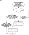
- Fig.3 is an example flowchart of implementing the method for establishing a PCEP session given by the embodiment based on the scenario as in Fig.1 , the flow including steps as follows.
- a PCE activates a flow of PCEP session establishment once a requirement for establishing a PCEP session is met, provided that: the PCE finds, via a finding mechanism, a neighboring PCE per se; and a TCP monitoring service has been created for the PCE at a communicating port 4189.
- step 302 the PCE detects whether there is an established TCP connection to a peer PCE.
- step 303 when the PCE detects that there is an established TCP connection to a peer PCE, the flow goes to step 305; or when the PCE detects that there is no established TCP connection to a peer PCE, the flow goes to step 304.
- step 304 the local PCE actively connects the peer PCE as a client of a TCP connection; and the flow goes to step 302;
- step 305 the PCE detects whether there are multiple TCP connections established with the peer PCE; when the PCE detects multiple TCP connections established, the flow goes to step 306; otherwise when the PCE detects no more than one established TCP connection, the flow goes to step 307.
- step 306 any TCP connection between the local PCE and the peer PCE is disconnected; the local PCE waits a random period of time; and then the flow goes to step 304.
- each of both TCP connection ends determines a local random period of time, and waits the local random period of time before initiating a TCP connection again.
- step 307 the PCE detects whether the PCEP session has been established with the peer PCE; when the PCE detects that the PCEP session has been established, the flow ends; otherwise when the PCE detects that the PCEP session has not been established, the flow goes to step 308.
- step 308 the PCE starts to establish the PCEP session with the peer.
Landscapes
- Engineering & Computer Science (AREA)
- Computer Networks & Wireless Communication (AREA)
- Signal Processing (AREA)
- Computer Security & Cryptography (AREA)
- Computer And Data Communications (AREA)
- Communication Control (AREA)
Description
- The disclosure relates to the field of Path Computation Element (PCE) Communication Protocol (PCEP) technology, and in particular to a method and device for establishing a PCEP session.
- Distributed in an Automatically Switched Optical Network (ASON) architecture defined in ITU-T G.8080 are control-plane node equipment each containing a Route Controller (RC) component providing a connection controller with route information for connection inside a domain of responsibility. Such route information is end-to-end, or may be based on next-hop. In addition, to achieve network management, the RC can also respond to topology requesting information.
- With development of a Multi-Protocol Label Switching (MPLS) / Generalized Multi-Protocol Label Switching (GMPLS) network, network topology becomes increasingly complicated with enormous amount of routes, and path computation becomes increasingly complicated as well. Meanwhile, traffic projecting requires a network equipment to perform route computation under complicated constraints. such complicated computation often requires a lot of CPU computing resources and memory resources, impacting hardware performance of the network equipment and stability of the entire network to some extent.
- Accordingly, an IETF PCE workgroup proposes an MPLS/GMPLS network structure based on a Path Computation Element (PCE). In such a structure, based on known network topology and a known constraint, a PCE, as a functional entity dedicated to path computation in a management domain, computes an optimal pat meeting the constraint according to a request of a Path Computation Client (PCC). A PCE may be located anywhere in the network, for example by being integrated in a network equipment such as a Label Switch Route (LSR) or an Operating System (OS), or may be a separate equipment. Communication between a PCC and a PCE as well as between a PCE and a PCE is performed via a PCE Communication Protocol (PCEP).
- RFC 5440 describes in particular a PCEP architecture including a transport layer adopting a TCP, a transport port 4189, with 7 PCEP message type defined. RFC 5440 specifies that what must be accomplished at an initial stage of establishing communication between a PCC and a PCE are: 1) establishment of a TCP connection between the PCC and the PCE via three handshakes; and 2) establishment of a PCEP session based on the TCP connection. RFC 5440 specifies two constraints that: 1) at any time, any pair of PCEP communicating ends can have only one PCEP session ; 2) at any time, there can be only one TCP connection between any pair of PCEP communicating ends.
- However, in multi-PCE collaboration, including intra-domain collaborative computation by multiple PCEs, inter-domain collaborative computation by multiple PCEs, and collaborative computation by parent and offspring PCEs in a hierarchic PCE architecture, a PCE will serve as a TCP server in monitoring at a port 4189 a message sent by a PCC, and also will serve as a TCP client in actively seeking connection to another PCE for PCEP message exchange. An implementing mechanism among such PCEs in collaborative computation has to be formulated to meet the two constraints.
- RAUL MUNOZ ET AL: "An open GMPLS-enabled control plane testbed for remote development and experimentation of PCE-based path computation algorithms", XP032030968 presents an open GMPLS-enabled control plane testbed, based on the infrastructure of the ADRENALINE testbed, to allow researchers the remote development and experimentation of dynamic PCE-based path computation algorithms through an open API.
- JP VASSEUR ET AL: "Path Computation Element (PCE) Communication Protocol (PCEP); rfc5440.txt", PATH COMPUTATION ELEMENT (PCE) COMMUNICATION PROTOCOL (PCEP); RFC5440.TXT, INTERNET ENGINEERING TASK FORCE, IETF; STANDARD, INTERNET SOCIETY (ISOC) 4, RUE DES FALAISES CH- 1205 GENEVA, SWITZERLAND, 1 March 2009 (2009-03-01), XP015065509, specifies the Path Computation Element (PCE) Communication Protocol (PCEP) for communications between a Pathe Computation Client (PCC) and a PCE, or between two PCEs. Such interactions include path computation requests and path computation replies as well as notifications of specific states related to the use of a PCE in the context of Multiprotocol Label Switching (MPLS) and Generalized MPLS (GMPLS) Traffic Engineering. PCEP is designed to be flexible and extensible so as to easily allow for the addition of further messages and objects, should further requirements be expressed in the future.
- In view of this, it is desired that embodiments of the disclosure provide a method and device for establishing a PCEP session, capable of establishing, in a scenario of multi-PCE collaborative computation, a PCEP session among PCEs in collaborative computation while meeting the two constraints.
- The present invention provides for a method for establishing a Path Computation Element Communication Protocol (PCEP) session as defined in
claim 1 and for a device for establishing a Path Computation Element Communication Protocol (PCEP) session, as defined inclaim 2. - Embodiments of the disclosure provide a solution for PCEP session establishment in a scenario of multi-PCE collaborative computation, meeting two protocol-specified constraints that: 1) at any time, any pair of PCEP communicating ends can have only one PCEP session ; 2) at any time, there can be only one TCP connection between any pair of PCEP communicating ends.
-
-
Fig.1 is a schematic diagram of a scenario of PCEP session establishment among three PCEs in multi-PCE collaborative path computation according to an embodiment of the disclosure; -
Fig.2 is a schematic diagram of inter-PCE exchange in a flow of PCEP session establishment according toEmbodiment 2 of the disclosure; -
Fig.3 is a processing flow of a single PCE in a flow of PCEP session establishment according toEmbodiment 3 of the disclosure; and -
Fig.4 is a schematic diagram of a structure of a device for establishing a PCEP session according toEmbodiment 3 of the disclosure. - To clearly show a technical problem to be solved, a technical solution, and beneficial effects of the present disclosure, the present disclosure is further elaborated below with reference to the drawings and embodiments.
-
Fig.1 is a schematic diagram of a scenario of PCEP session establishment among three PCEs in multi-PCE collaborative path computation according to an embodiment of the disclosure. In an MPLS/GMPLS network, PCE1, PCE2, and PCE3 are required to perform collaborative path computation. Assuming that path computation is required among all three PCEs, the three PCEs therefore neighbor each other, and a PCEP session is required to be established between each two of the three PCEs. - In the embodiment, at a Path Computation Client (PCC) or a Path computation Element (PCE) node equipment side, when it is required to establish a PCEP session between the PCC and another PCE or between the PCE and another PCC or another PCE, an attribute of the PCC or the PCE node equipment as a communicating end of a TCP connection for the PCEP session is allocated, via static configuration or dynamic designation, as a server (intercepting connection of another PCC or PCE at a communication port 4189) or a client (actively seeking connection to a PCC or PCE node performing a monitoring service at a communication port 4189).
- A device for implementing the method for establishing a PCEP session as given by the embodiment is provided accordingly, the device including:
- a communicating end attribute configuring element configured for: at a PCC or a PCE node equipment side, when it is required to establish a PCEP session between the PCC and another PCE or between the PCE and another PCC or another PCE, allocating, via static configuration or dynamic designation, an attribute of the PCC or the PCE node equipment as a communicating end of a TCP connection for the PCEP session as a server or a client; and
- a PCEP session establishing element is configured for: establishing the PCEP session between the PCC and a peer PCE, or establishing the PCEP session between the PCE and a peer PCC or a peer PCE.
- With an example of a scenario as in
Fig.1 , when it is required to establish a PCEP session between PCE1 and PCE2, the communicating end attribute configuring element allocates, via static configuration or dynamic designation, the attribute of PCE1 as a communicating end of a TCP connection for the PCEP session as a server, and the attribute of PCE2 as a communicating end of a TCP connection for the PCEP session as a client. - With the static configuration, the attribute as a client or as a server in a PCEP session is designated before a node equipment or device deployed with a PCE function activates the PCE function.
- With the dynamic designation, after a node equipment or device deployed with a PCE function activates the PCE function, the attribute as a client or as a server in a PCEP session is designated in accordance with a preset dynamic designation mechanism. the dynamic designation mechanism may be an electing mechanism, as described in
Embodiment 2. - A flow of PCEP session establishment according to
Embodiment 2 is as shown inFig.2 . At a PCC or a PCE node equipment side, when it is required to establish a PCEP session between the PCC and another PCE or between the PCE and another PCC or another PCE, an attribute of the PCC or the PCE node equipment as a communicating end of a TCP connection for the PCEP session is automatically allocated, via an electing mechanism, as a server (intercepting connection of another PCC or PCE at a communication port 4189) or a client (actively seeking connection to a PCC or PCE node performing a monitoring service at a communication port 4189). - A device for implementing the method for establishing a PCEP session as given by the embodiment is provided accordingly, the device including:
- an electing element configured for: at a PCC or a PCE node equipment side, when it is required to establish a PCEP session between the PCC and another PCE or between the PCE and another PCC or another PCE, automatically allocating, via an electing mechanism, an attribute of the PCC or the PCE node equipment as a communicating end of a TCP connection for the PCEP session as a server or a client; and
- a PCEP session establishing element configured for: establishing the PCEP session between the PCC and a peer PCE, or establishing the PCEP session between the PCE and a peer PCC or a peer PCE.
- The electing mechanism may include but be not limited to that:
- (1) in accordance with an IP address of a PCC or PCE at either of both ends between which the PCEP session is to be established, a PCC or a PCE with a greater IP address is elected as a server (or as a client);
- (2) in accordance with the size of an area identifier (area ID) of a PCC or PCE at either of both ends between which the PCEP session is to be established in an autonomous domain, a PCC or PCE with a greater area ID in the autonomous domain is elected as a server (or as a client); or
- (3) in accordance with the size of an autonomous domain identifier of an autonomous domain to which a PCC or PCE at either of both ends between which the PCEP session is to be established belongs, a PCC or a PCE with a greater autonomous domain identifier is elected as a server (or as a client).
- In addition, the attribute, as a server or as a client, of either of both ends that are to be in PCEP communication may be elected in accordance with any other unique, comparable parameter.
-
Fig.2 is an example flowchart of implementing the method for establishing a PCEP session given by the embodiment based on the scenario as inFig.1 , the flow including steps as follows. - In
step 1, after activation, each of PCE1, PCE2, and PCE3 finds, via a finding mechanism, a neighboring PCE per se. PCE1 neighbors PCE2 and PCE3; PCE2 neighbors PCE1 and PCE3; and PCE3 neighbors PCE1 and PCE2. - In
step 2, PCE1, PCE2, and PCE3 follow a same electing mechanism which, in the embodiment, is that: a PCE with a greater autonomous domain identifier serves as a TCP server in a PCEP session, and a PCE with a smaller autonomous domain identifier serves as a TCP client in a PCEP session. Therefore, a TCP connection table is produced as follows.PCE session TCP server TCP client PCE1 <->PCE2 PCE2 PCE1 PCE1 <->PCE3 PCE3 PCE1 PCE2<->PCE3 PCE3 PCE1 - In
step 3, one of PCE1, PCE2, and PCE3 initiates a TCP connection request with a respective TCP server according to the TCP connection table produced by election. Here, a process of activation of a TCP monitoring service by a PCE at a communicating port 4189 is omitted;
In step 4, PCE1 receives TCP connection succeeds acknowledgements sent respectively by PCE2 and PCE3; and PCE2 receives a TCP connection succeeds acknowledgement sent by PCE3. - In step 5, PCE1 establishes a PCEP session respectively with PCE2 and PCE3; and PCE2 establishes a PCEP session with PCE3.
- In the embodiment, at a PCC or a PCE node equipment side, when meeting a requirement for triggering establishment of a PCEP session, the PCC or the PCE first detects whether there is a TCP connection, established via three handshakes, to a peer PCE or a peer PCC with which the PCEP session is to be established; when there is no established TCP connection, the PCC or the PCE actively seeks a TCP connection to the peer as a client; when there is an established TCP connection, the PCC or the PCE detects whether there are multiple TCP connections established; when no more than one established TCP connection is detected and no PCEP session has been established with the peer PCE or the peer PCC, a flow of PCEP session establishment is activated; otherwise when multiple TCP connections established are detected, the multiple TCP connections detected are simultaneously disconnected, and the PCC or the PCE actively seeks a TCP connection to the peer as a client after waiting a random period of time. Note that no PCEP session can be established between two PCCs; a PCEP session can be established only between a PCC and a PCE, or between two PCEs.
- A
device 400 for implementing the method for establishing a PCEP session as given by the embodiment is provided accordingly, the device applying to a PCC or a PCE; as shown inFig.4 , thedevice 400 includes: - a first determining
element 401 configured for: when a requirement for triggering establishment of a PCEP session is met, detecting whether there is an established TCP connection to a peer PCE or a peer PCC with which the PCEP session is to be established; - an
active connection element 402 configured for: when there is no established TCP connection, actively seeking a TCP connection to the peer as a client; - a second determining
element 403 configured for: when there is an established TCP connection, detecting whether there are multiple TCP connections established; - a third determining
element 404 configured for: when no more than one established TCP connection is detected, determining whether a PCEP session has been established with the peer PCE or the peer PCC; - a PCEP
session establishing element 405 configured for: when no more than one established TCP connection is detected and no PCEP session has been established with the peer PCE or the peer PCC, activating a flow of PCEP session establishment; and - a
re-connecting element 406 configured for: when multiple TCP connections established are detected, simultaneously disconnecting the multiple TCP connections detected, and actively seeking a TCP connection to the peer as a client after waiting a random period of time. - The requirement for triggering establishment of a PCEP session may include at least a PCE node activation or a special event; the special event may include at least a timer event or a PCEP message event.
-
Fig.3 is an example flowchart of implementing the method for establishing a PCEP session given by the embodiment based on the scenario as inFig.1 , the flow including steps as follows. - In
step 301, a PCE activates a flow of PCEP session establishment once a requirement for establishing a PCEP session is met, provided that: the PCE finds, via a finding mechanism, a neighboring PCE per se; and a TCP monitoring service has been created for the PCE at a communicating port 4189. - In
step 302, the PCE detects whether there is an established TCP connection to a peer PCE. - In step 303, when the PCE detects that there is an established TCP connection to a peer PCE, the flow goes to step 305; or when the PCE detects that there is no established TCP connection to a peer PCE, the flow goes to step 304.
- In
step 304, the local PCE actively connects the peer PCE as a client of a TCP connection; and the flow goes to step 302;
Instep 305, the PCE detects whether there are multiple TCP connections established with the peer PCE; when the PCE detects multiple TCP connections established, the flow goes to step 306; otherwise when the PCE detects no more than one established TCP connection, the flow goes to step 307. - In
step 306, any TCP connection between the local PCE and the peer PCE is disconnected; the local PCE waits a random period of time; and then the flow goes to step 304. - In the step, each of both TCP connection ends determines a local random period of time, and waits the local random period of time before initiating a TCP connection again.
- In
step 307, the PCE detects whether the PCEP session has been established with the peer PCE; when the PCE detects that the PCEP session has been established, the flow ends; otherwise when the PCE detects that the PCEP session has not been established, the flow goes to step 308. - In
step 308, the PCE starts to establish the PCEP session with the peer. - What described are merely embodiments of the disclosure and are not intended to limit the scope of the disclosure.
Claims (2)
- A method for establishing a Path Computation Element Communication Protocol, PCEP, session, the method characterised in that the method comprises steps of:at a Path Computation Client, PCC, or a Path computation Element, PCE, node equipment side, when it is required to establish a PCEP session between the PCC and another PCE or between the PCE and another PCC or another PCE, automatically allocating, via an electing mechanism, an attribute of the PCC or the PCE node equipment as a communicating end of a TCP connection for the PCEP session as a server or a client,wherein the electing mechanism comprises at least that of:electing a PCC or a PCE with a greater IP address as a server or a client;electing in an autonomous domain a PCC or a PCE with a greater area identifier as a server or a client; orelecting a PCC or a PCE with a greater autonomous domain identifier as a server or a client.
- A device for establishing a Path Computation Element Communication Protocol, PCEP, session, applying to a Path Computation Client, PCC, or a Path computation Element, PCE, node equipment side,
the device characterised in that the device comprises an electing element and a PCEP session establishing element, whereinthe electing element is configured for: when it is required to establish a PCEP session between the PCC and another PCE or between the PCE and another PCC or another PCE, automatically allocating, via an electing mechanism, an attribute of the PCC or the PCE node equipment as a communicating end of a TCP connection for the PCEP session as a server or a client; andthe PCEP session establishing element is configured for: establishing the PCEP session between the PCC and a peer PCE, or establishing the PCEP session between the PCE and a peer PCC or a peer PCE,wherein the electing mechanism comprises at least that of:electing a PCC or a PCE with a greater IP address as a server or a client;electing in an autonomous domain a PCC or a PCE with an area identifier as a server or a client; orelecting a PCC or a PCE with a greater autonomous domain identifier as a server or a client.
Applications Claiming Priority (2)
| Application Number | Priority Date | Filing Date | Title |
|---|---|---|---|
| CN201210103317.9A CN102624745B (en) | 2012-04-10 | 2012-04-10 | Method and device for establishing PCEP session |
| PCT/CN2013/073984 WO2013152718A1 (en) | 2012-04-10 | 2013-04-09 | Path computation element communication protocol session establishment method and device |
Publications (3)
| Publication Number | Publication Date |
|---|---|
| EP2824886A1 EP2824886A1 (en) | 2015-01-14 |
| EP2824886A4 EP2824886A4 (en) | 2015-07-01 |
| EP2824886B1 true EP2824886B1 (en) | 2020-05-20 |
Family
ID=46564429
Family Applications (1)
| Application Number | Title | Priority Date | Filing Date |
|---|---|---|---|
| EP13775429.7A Active EP2824886B1 (en) | 2012-04-10 | 2013-04-09 | Path computation element communication protocol session establishment method and device |
Country Status (4)
| Country | Link |
|---|---|
| US (1) | US9948722B2 (en) |
| EP (1) | EP2824886B1 (en) |
| CN (1) | CN102624745B (en) |
| WO (1) | WO2013152718A1 (en) |
Families Citing this family (8)
| Publication number | Priority date | Publication date | Assignee | Title |
|---|---|---|---|---|
| CN102624745B (en) | 2012-04-10 | 2015-01-28 | 中兴通讯股份有限公司 | Method and device for establishing PCEP session |
| CN104639557B (en) * | 2015-02-16 | 2018-03-09 | 华为技术有限公司 | A kind of method, system and equipment for establishing PCEP sessions |
| US10516767B2 (en) * | 2016-04-18 | 2019-12-24 | Globalfoundries Inc. | Unifying realtime and static data for presenting over a web service |
| US11190616B2 (en) * | 2018-10-15 | 2021-11-30 | Liveperson, Inc. | Dynamic endpoint communication channels |
| CN111865776B (en) * | 2019-11-07 | 2021-07-06 | 中兴通讯股份有限公司 | Path creation method, device, system and storage medium |
| CN112398863A (en) * | 2020-11-19 | 2021-02-23 | 全知科技(杭州)有限责任公司 | Data analysis method for incomplete flow of TCP long connection |
| CN113193988B (en) * | 2021-04-09 | 2022-08-12 | 烽火通信科技股份有限公司 | Multi-PCE path computation interaction method and system |
| CN115242858B (en) * | 2022-07-21 | 2024-02-09 | 山石网科通信技术股份有限公司 | Message processing method, device, electronic equipment and computer readable storage medium |
Family Cites Families (8)
| Publication number | Priority date | Publication date | Assignee | Title |
|---|---|---|---|---|
| CN101335692B (en) * | 2007-06-27 | 2013-03-13 | 华为技术有限公司 | Method for negotiating security capability between PCC and PCE and network system thereof |
| US8769129B2 (en) | 2007-11-14 | 2014-07-01 | Juniper Networks, Inc. | Server initiated secure network connection |
| US8358662B2 (en) | 2008-08-30 | 2013-01-22 | Futurewei Technologies, Inc. | Creating and maintaining traffic engineered database for path computation element |
| BRPI0924228A2 (en) | 2009-01-22 | 2016-01-26 | Ericsson Telefon Ab L M | method for allocating address on a network, network node, and, computer readable medium |
| US20110225230A1 (en) | 2010-03-15 | 2011-09-15 | Russ Craig F | Method and apparatus for detecting active and orphan session-based connections |
| CN101984602A (en) * | 2010-11-05 | 2011-03-09 | 中兴通讯股份有限公司 | Path calculation method, system and node equipment |
| CN102238185B (en) | 2011-07-19 | 2017-08-11 | 南京中兴新软件有限责任公司 | Session establishing method and system |
| CN102624745B (en) | 2012-04-10 | 2015-01-28 | 中兴通讯股份有限公司 | Method and device for establishing PCEP session |
-
2012
- 2012-04-10 CN CN201210103317.9A patent/CN102624745B/en active Active
-
2013
- 2013-04-09 US US14/389,485 patent/US9948722B2/en active Active
- 2013-04-09 WO PCT/CN2013/073984 patent/WO2013152718A1/en not_active Ceased
- 2013-04-09 EP EP13775429.7A patent/EP2824886B1/en active Active
Non-Patent Citations (1)
| Title |
|---|
| None * |
Also Published As
| Publication number | Publication date |
|---|---|
| EP2824886A4 (en) | 2015-07-01 |
| US9948722B2 (en) | 2018-04-17 |
| WO2013152718A1 (en) | 2013-10-17 |
| EP2824886A1 (en) | 2015-01-14 |
| CN102624745A (en) | 2012-08-01 |
| US20150095506A1 (en) | 2015-04-02 |
| CN102624745B (en) | 2015-01-28 |
Similar Documents
| Publication | Publication Date | Title |
|---|---|---|
| US9948722B2 (en) | Path computation element communication protocol session establishment method and device | |
| US8543718B2 (en) | Technique for efficiently and dynamically maintaining bidirectional forwarding detection on a bundle of links | |
| US9813329B2 (en) | Method for multi-chassis redundancy using anycast and GTP TEID | |
| TWI461030B (en) | Resource Retention Agreement under the condition of fast rerouting | |
| JP4769869B2 (en) | Method and router for protocol process migration | |
| US10848416B2 (en) | Reduced configuration for multi-stage network fabrics | |
| US9537756B2 (en) | Method for synchronized BGP and VRRP failover of a network device in a network | |
| CN110912780A (en) | High-availability cluster detection method, system and controlled terminal | |
| US20030123457A1 (en) | Apparatus and method for distributed software implementation of OSPF protocol | |
| RU2645296C2 (en) | Routing services "point-to-multipoint" in multi-domain network | |
| EP3637697A1 (en) | Method for determining path computation element and communications device | |
| US20180270149A1 (en) | Method and Device for Processing Routing Status and/or Policy Information | |
| WO2012058915A1 (en) | Method, system and node equipment for path computation | |
| WO2016019866A1 (en) | Tunnel between interior border gateway protocol neighbors | |
| US8923312B2 (en) | OSPF nonstop routing synchronization nack | |
| CN119728552B (en) | A method, apparatus, device and storage medium for network element load balancing | |
| EP3099010B1 (en) | Network path computation method, apparatus and system | |
| KR20200072941A (en) | Method and apparatus for handling VRRP(Virtual Router Redundancy Protocol)-based network failure using real-time fault detection | |
| WO2022083763A1 (en) | Method and apparatus for establishing border gateway protocol (bgp) neighbors, device and system | |
| US10735252B2 (en) | Outside router fault detection | |
| WO2018077313A1 (en) | Connection capability notification method and device | |
| US12120020B2 (en) | Delaying resource reservation protocol label-switched path signaling through a restarting network device | |
| CN102655635B (en) | A kind of method and network equipment setting up neighborhood | |
| JP6017037B6 (en) | System and method for using RSVP HELLO suppression for graceful restart capable neighbors | |
| JP2015527825A (en) | System and method for using RSVPHELLO suppression for graceful restart capable neighbors |
Legal Events
| Date | Code | Title | Description |
|---|---|---|---|
| PUAI | Public reference made under article 153(3) epc to a published international application that has entered the european phase |
Free format text: ORIGINAL CODE: 0009012 |
|
| 17P | Request for examination filed |
Effective date: 20141009 |
|
| AK | Designated contracting states |
Kind code of ref document: A1 Designated state(s): AL AT BE BG CH CY CZ DE DK EE ES FI FR GB GR HR HU IE IS IT LI LT LU LV MC MK MT NL NO PL PT RO RS SE SI SK SM TR |
|
| AX | Request for extension of the european patent |
Extension state: BA ME |
|
| RA4 | Supplementary search report drawn up and despatched (corrected) |
Effective date: 20150601 |
|
| RIC1 | Information provided on ipc code assigned before grant |
Ipc: H04L 12/70 20130101ALI20150526BHEP Ipc: H04L 29/06 20060101AFI20150526BHEP |
|
| DAX | Request for extension of the european patent (deleted) | ||
| STAA | Information on the status of an ep patent application or granted ep patent |
Free format text: STATUS: EXAMINATION IS IN PROGRESS |
|
| 17Q | First examination report despatched |
Effective date: 20180119 |
|
| GRAP | Despatch of communication of intention to grant a patent |
Free format text: ORIGINAL CODE: EPIDOSNIGR1 |
|
| STAA | Information on the status of an ep patent application or granted ep patent |
Free format text: STATUS: GRANT OF PATENT IS INTENDED |
|
| RIC1 | Information provided on ipc code assigned before grant |
Ipc: H04L 12/717 20130101ALI20191204BHEP Ipc: H04L 29/06 20060101AFI20191204BHEP Ipc: H04L 29/08 20060101ALI20191204BHEP |
|
| INTG | Intention to grant announced |
Effective date: 20200107 |
|
| GRAS | Grant fee paid |
Free format text: ORIGINAL CODE: EPIDOSNIGR3 |
|
| GRAA | (expected) grant |
Free format text: ORIGINAL CODE: 0009210 |
|
| STAA | Information on the status of an ep patent application or granted ep patent |
Free format text: STATUS: THE PATENT HAS BEEN GRANTED |
|
| AK | Designated contracting states |
Kind code of ref document: B1 Designated state(s): AL AT BE BG CH CY CZ DE DK EE ES FI FR GB GR HR HU IE IS IT LI LT LU LV MC MK MT NL NO PL PT RO RS SE SI SK SM TR |
|
| REG | Reference to a national code |
Ref country code: GB Ref legal event code: FG4D |
|
| REG | Reference to a national code |
Ref country code: CH Ref legal event code: EP |
|
| REG | Reference to a national code |
Ref country code: DE Ref legal event code: R096 Ref document number: 602013069274 Country of ref document: DE |
|
| REG | Reference to a national code |
Ref country code: AT Ref legal event code: REF Ref document number: 1273369 Country of ref document: AT Kind code of ref document: T Effective date: 20200615 |
|
| REG | Reference to a national code |
Ref country code: LT Ref legal event code: MG4D |
|
| REG | Reference to a national code |
Ref country code: NL Ref legal event code: MP Effective date: 20200520 |
|
| PG25 | Lapsed in a contracting state [announced via postgrant information from national office to epo] |
Ref country code: FI Free format text: LAPSE BECAUSE OF FAILURE TO SUBMIT A TRANSLATION OF THE DESCRIPTION OR TO PAY THE FEE WITHIN THE PRESCRIBED TIME-LIMIT Effective date: 20200520 Ref country code: LT Free format text: LAPSE BECAUSE OF FAILURE TO SUBMIT A TRANSLATION OF THE DESCRIPTION OR TO PAY THE FEE WITHIN THE PRESCRIBED TIME-LIMIT Effective date: 20200520 Ref country code: PT Free format text: LAPSE BECAUSE OF FAILURE TO SUBMIT A TRANSLATION OF THE DESCRIPTION OR TO PAY THE FEE WITHIN THE PRESCRIBED TIME-LIMIT Effective date: 20200921 Ref country code: SE Free format text: LAPSE BECAUSE OF FAILURE TO SUBMIT A TRANSLATION OF THE DESCRIPTION OR TO PAY THE FEE WITHIN THE PRESCRIBED TIME-LIMIT Effective date: 20200520 Ref country code: GR Free format text: LAPSE BECAUSE OF FAILURE TO SUBMIT A TRANSLATION OF THE DESCRIPTION OR TO PAY THE FEE WITHIN THE PRESCRIBED TIME-LIMIT Effective date: 20200821 Ref country code: IS Free format text: LAPSE BECAUSE OF FAILURE TO SUBMIT A TRANSLATION OF THE DESCRIPTION OR TO PAY THE FEE WITHIN THE PRESCRIBED TIME-LIMIT Effective date: 20200920 Ref country code: NO Free format text: LAPSE BECAUSE OF FAILURE TO SUBMIT A TRANSLATION OF THE DESCRIPTION OR TO PAY THE FEE WITHIN THE PRESCRIBED TIME-LIMIT Effective date: 20200820 |
|
| PG25 | Lapsed in a contracting state [announced via postgrant information from national office to epo] |
Ref country code: HR Free format text: LAPSE BECAUSE OF FAILURE TO SUBMIT A TRANSLATION OF THE DESCRIPTION OR TO PAY THE FEE WITHIN THE PRESCRIBED TIME-LIMIT Effective date: 20200520 Ref country code: RS Free format text: LAPSE BECAUSE OF FAILURE TO SUBMIT A TRANSLATION OF THE DESCRIPTION OR TO PAY THE FEE WITHIN THE PRESCRIBED TIME-LIMIT Effective date: 20200520 Ref country code: BG Free format text: LAPSE BECAUSE OF FAILURE TO SUBMIT A TRANSLATION OF THE DESCRIPTION OR TO PAY THE FEE WITHIN THE PRESCRIBED TIME-LIMIT Effective date: 20200820 Ref country code: LV Free format text: LAPSE BECAUSE OF FAILURE TO SUBMIT A TRANSLATION OF THE DESCRIPTION OR TO PAY THE FEE WITHIN THE PRESCRIBED TIME-LIMIT Effective date: 20200520 |
|
| REG | Reference to a national code |
Ref country code: AT Ref legal event code: MK05 Ref document number: 1273369 Country of ref document: AT Kind code of ref document: T Effective date: 20200520 |
|
| PG25 | Lapsed in a contracting state [announced via postgrant information from national office to epo] |
Ref country code: AL Free format text: LAPSE BECAUSE OF FAILURE TO SUBMIT A TRANSLATION OF THE DESCRIPTION OR TO PAY THE FEE WITHIN THE PRESCRIBED TIME-LIMIT Effective date: 20200520 Ref country code: NL Free format text: LAPSE BECAUSE OF FAILURE TO SUBMIT A TRANSLATION OF THE DESCRIPTION OR TO PAY THE FEE WITHIN THE PRESCRIBED TIME-LIMIT Effective date: 20200520 |
|
| PG25 | Lapsed in a contracting state [announced via postgrant information from national office to epo] |
Ref country code: ES Free format text: LAPSE BECAUSE OF FAILURE TO SUBMIT A TRANSLATION OF THE DESCRIPTION OR TO PAY THE FEE WITHIN THE PRESCRIBED TIME-LIMIT Effective date: 20200520 Ref country code: IT Free format text: LAPSE BECAUSE OF FAILURE TO SUBMIT A TRANSLATION OF THE DESCRIPTION OR TO PAY THE FEE WITHIN THE PRESCRIBED TIME-LIMIT Effective date: 20200520 Ref country code: AT Free format text: LAPSE BECAUSE OF FAILURE TO SUBMIT A TRANSLATION OF THE DESCRIPTION OR TO PAY THE FEE WITHIN THE PRESCRIBED TIME-LIMIT Effective date: 20200520 Ref country code: CZ Free format text: LAPSE BECAUSE OF FAILURE TO SUBMIT A TRANSLATION OF THE DESCRIPTION OR TO PAY THE FEE WITHIN THE PRESCRIBED TIME-LIMIT Effective date: 20200520 Ref country code: RO Free format text: LAPSE BECAUSE OF FAILURE TO SUBMIT A TRANSLATION OF THE DESCRIPTION OR TO PAY THE FEE WITHIN THE PRESCRIBED TIME-LIMIT Effective date: 20200520 Ref country code: SM Free format text: LAPSE BECAUSE OF FAILURE TO SUBMIT A TRANSLATION OF THE DESCRIPTION OR TO PAY THE FEE WITHIN THE PRESCRIBED TIME-LIMIT Effective date: 20200520 Ref country code: EE Free format text: LAPSE BECAUSE OF FAILURE TO SUBMIT A TRANSLATION OF THE DESCRIPTION OR TO PAY THE FEE WITHIN THE PRESCRIBED TIME-LIMIT Effective date: 20200520 Ref country code: DK Free format text: LAPSE BECAUSE OF FAILURE TO SUBMIT A TRANSLATION OF THE DESCRIPTION OR TO PAY THE FEE WITHIN THE PRESCRIBED TIME-LIMIT Effective date: 20200520 |
|
| REG | Reference to a national code |
Ref country code: DE Ref legal event code: R097 Ref document number: 602013069274 Country of ref document: DE |
|
| PG25 | Lapsed in a contracting state [announced via postgrant information from national office to epo] |
Ref country code: SK Free format text: LAPSE BECAUSE OF FAILURE TO SUBMIT A TRANSLATION OF THE DESCRIPTION OR TO PAY THE FEE WITHIN THE PRESCRIBED TIME-LIMIT Effective date: 20200520 Ref country code: PL Free format text: LAPSE BECAUSE OF FAILURE TO SUBMIT A TRANSLATION OF THE DESCRIPTION OR TO PAY THE FEE WITHIN THE PRESCRIBED TIME-LIMIT Effective date: 20200520 |
|
| PLBE | No opposition filed within time limit |
Free format text: ORIGINAL CODE: 0009261 |
|
| STAA | Information on the status of an ep patent application or granted ep patent |
Free format text: STATUS: NO OPPOSITION FILED WITHIN TIME LIMIT |
|
| 26N | No opposition filed |
Effective date: 20210223 |
|
| PG25 | Lapsed in a contracting state [announced via postgrant information from national office to epo] |
Ref country code: SI Free format text: LAPSE BECAUSE OF FAILURE TO SUBMIT A TRANSLATION OF THE DESCRIPTION OR TO PAY THE FEE WITHIN THE PRESCRIBED TIME-LIMIT Effective date: 20200520 |
|
| REG | Reference to a national code |
Ref country code: DE Ref legal event code: R079 Ref document number: 602013069274 Country of ref document: DE Free format text: PREVIOUS MAIN CLASS: H04L0029060000 Ipc: H04L0065000000 |
|
| PG25 | Lapsed in a contracting state [announced via postgrant information from national office to epo] |
Ref country code: MC Free format text: LAPSE BECAUSE OF FAILURE TO SUBMIT A TRANSLATION OF THE DESCRIPTION OR TO PAY THE FEE WITHIN THE PRESCRIBED TIME-LIMIT Effective date: 20200520 |
|
| PG25 | Lapsed in a contracting state [announced via postgrant information from national office to epo] |
Ref country code: LU Free format text: LAPSE BECAUSE OF NON-PAYMENT OF DUE FEES Effective date: 20210409 |
|
| REG | Reference to a national code |
Ref country code: BE Ref legal event code: MM Effective date: 20210430 |
|
| PG25 | Lapsed in a contracting state [announced via postgrant information from national office to epo] |
Ref country code: LI Free format text: LAPSE BECAUSE OF NON-PAYMENT OF DUE FEES Effective date: 20210430 Ref country code: CH Free format text: LAPSE BECAUSE OF NON-PAYMENT OF DUE FEES Effective date: 20210430 |
|
| PG25 | Lapsed in a contracting state [announced via postgrant information from national office to epo] |
Ref country code: IE Free format text: LAPSE BECAUSE OF NON-PAYMENT OF DUE FEES Effective date: 20210409 |
|
| PG25 | Lapsed in a contracting state [announced via postgrant information from national office to epo] |
Ref country code: BE Free format text: LAPSE BECAUSE OF NON-PAYMENT OF DUE FEES Effective date: 20210430 |
|
| PG25 | Lapsed in a contracting state [announced via postgrant information from national office to epo] |
Ref country code: HU Free format text: LAPSE BECAUSE OF FAILURE TO SUBMIT A TRANSLATION OF THE DESCRIPTION OR TO PAY THE FEE WITHIN THE PRESCRIBED TIME-LIMIT; INVALID AB INITIO Effective date: 20130409 |
|
| PG25 | Lapsed in a contracting state [announced via postgrant information from national office to epo] |
Ref country code: CY Free format text: LAPSE BECAUSE OF FAILURE TO SUBMIT A TRANSLATION OF THE DESCRIPTION OR TO PAY THE FEE WITHIN THE PRESCRIBED TIME-LIMIT Effective date: 20200520 |
|
| PG25 | Lapsed in a contracting state [announced via postgrant information from national office to epo] |
Ref country code: MK Free format text: LAPSE BECAUSE OF FAILURE TO SUBMIT A TRANSLATION OF THE DESCRIPTION OR TO PAY THE FEE WITHIN THE PRESCRIBED TIME-LIMIT Effective date: 20200520 |
|
| PG25 | Lapsed in a contracting state [announced via postgrant information from national office to epo] |
Ref country code: MT Free format text: LAPSE BECAUSE OF FAILURE TO SUBMIT A TRANSLATION OF THE DESCRIPTION OR TO PAY THE FEE WITHIN THE PRESCRIBED TIME-LIMIT Effective date: 20200520 |
|
| PGFP | Annual fee paid to national office [announced via postgrant information from national office to epo] |
Ref country code: FR Payment date: 20250310 Year of fee payment: 13 |
|
| PGFP | Annual fee paid to national office [announced via postgrant information from national office to epo] |
Ref country code: GB Payment date: 20250306 Year of fee payment: 13 |
|
| PGFP | Annual fee paid to national office [announced via postgrant information from national office to epo] |
Ref country code: DE Payment date: 20250305 Year of fee payment: 13 |
|
| PG25 | Lapsed in a contracting state [announced via postgrant information from national office to epo] |
Ref country code: TR Free format text: LAPSE BECAUSE OF FAILURE TO SUBMIT A TRANSLATION OF THE DESCRIPTION OR TO PAY THE FEE WITHIN THE PRESCRIBED TIME-LIMIT Effective date: 20200520 |