EP2824760A1 - Multi-axial antenna and method for use in downhole tools - Google Patents
Multi-axial antenna and method for use in downhole tools Download PDFInfo
- Publication number
- EP2824760A1 EP2824760A1 EP20140181867 EP14181867A EP2824760A1 EP 2824760 A1 EP2824760 A1 EP 2824760A1 EP 20140181867 EP20140181867 EP 20140181867 EP 14181867 A EP14181867 A EP 14181867A EP 2824760 A1 EP2824760 A1 EP 2824760A1
- Authority
- EP
- European Patent Office
- Prior art keywords
- bobbin
- coil
- grooves
- antenna system
- coils
- Prior art date
- Legal status (The legal status is an assumption and is not a legal conclusion. Google has not performed a legal analysis and makes no representation as to the accuracy of the status listed.)
- Withdrawn
Links
- 238000000034 method Methods 0.000 title description 10
- 238000004804 winding Methods 0.000 claims description 8
- 230000015572 biosynthetic process Effects 0.000 description 13
- 238000005755 formation reaction Methods 0.000 description 13
- 239000013598 vector Substances 0.000 description 7
- 238000005481 NMR spectroscopy Methods 0.000 description 4
- 238000005553 drilling Methods 0.000 description 4
- 239000002184 metal Substances 0.000 description 4
- 239000012811 non-conductive material Substances 0.000 description 4
- 239000004696 Poly ether ether ketone Substances 0.000 description 2
- 239000004020 conductor Substances 0.000 description 2
- 238000010586 diagram Methods 0.000 description 2
- 239000011152 fibreglass Substances 0.000 description 2
- 230000006698 induction Effects 0.000 description 2
- 238000005259 measurement Methods 0.000 description 2
- 229920002530 polyetherether ketone Polymers 0.000 description 2
- 229920001169 thermoplastic Polymers 0.000 description 2
- 239000004416 thermosoftening plastic Substances 0.000 description 2
- 239000004593 Epoxy Substances 0.000 description 1
- 230000005540 biological transmission Effects 0.000 description 1
- 229910010293 ceramic material Inorganic materials 0.000 description 1
- 238000000151 deposition Methods 0.000 description 1
- 230000005672 electromagnetic field Effects 0.000 description 1
- 230000007613 environmental effect Effects 0.000 description 1
- 238000005530 etching Methods 0.000 description 1
- 230000004907 flux Effects 0.000 description 1
- 239000011810 insulating material Substances 0.000 description 1
- 239000000463 material Substances 0.000 description 1
- 230000000149 penetrating effect Effects 0.000 description 1
- 230000035699 permeability Effects 0.000 description 1
- 230000000704 physical effect Effects 0.000 description 1
- 239000004033 plastic Substances 0.000 description 1
- 229920003023 plastic Polymers 0.000 description 1
- 229910000859 α-Fe Inorganic materials 0.000 description 1
Images



Classifications
-
- G—PHYSICS
- G01—MEASURING; TESTING
- G01V—GEOPHYSICS; GRAVITATIONAL MEASUREMENTS; DETECTING MASSES OR OBJECTS; TAGS
- G01V3/00—Electric or magnetic prospecting or detecting; Measuring magnetic field characteristics of the earth, e.g. declination, deviation
- G01V3/08—Electric or magnetic prospecting or detecting; Measuring magnetic field characteristics of the earth, e.g. declination, deviation operating with magnetic or electric fields produced or modified by objects or geological structures or by detecting devices
- G01V3/10—Electric or magnetic prospecting or detecting; Measuring magnetic field characteristics of the earth, e.g. declination, deviation operating with magnetic or electric fields produced or modified by objects or geological structures or by detecting devices using induction coils
- G01V3/104—Electric or magnetic prospecting or detecting; Measuring magnetic field characteristics of the earth, e.g. declination, deviation operating with magnetic or electric fields produced or modified by objects or geological structures or by detecting devices using induction coils using several coupled or uncoupled coils
-
- G—PHYSICS
- G01—MEASURING; TESTING
- G01V—GEOPHYSICS; GRAVITATIONAL MEASUREMENTS; DETECTING MASSES OR OBJECTS; TAGS
- G01V3/00—Electric or magnetic prospecting or detecting; Measuring magnetic field characteristics of the earth, e.g. declination, deviation
- G01V3/18—Electric or magnetic prospecting or detecting; Measuring magnetic field characteristics of the earth, e.g. declination, deviation specially adapted for well-logging
-
- H—ELECTRICITY
- H01—ELECTRIC ELEMENTS
- H01Q—ANTENNAS, i.e. RADIO AERIALS
- H01Q1/00—Details of, or arrangements associated with, antennas
- H01Q1/04—Adaptation for subterranean or subaqueous use
-
- H—ELECTRICITY
- H01—ELECTRIC ELEMENTS
- H01Q—ANTENNAS, i.e. RADIO AERIALS
- H01Q25/00—Antennas or antenna systems providing at least two radiating patterns
-
- H—ELECTRICITY
- H01—ELECTRIC ELEMENTS
- H01Q—ANTENNAS, i.e. RADIO AERIALS
- H01Q3/00—Arrangements for changing or varying the orientation or the shape of the directional pattern of the waves radiated from an antenna or antenna system
- H01Q3/26—Arrangements for changing or varying the orientation or the shape of the directional pattern of the waves radiated from an antenna or antenna system varying the relative phase or relative amplitude of energisation between two or more active radiating elements; varying the distribution of energy across a radiating aperture
-
- H—ELECTRICITY
- H01—ELECTRIC ELEMENTS
- H01Q—ANTENNAS, i.e. RADIO AERIALS
- H01Q7/00—Loop antennas with a substantially uniform current distribution around the loop and having a directional radiation pattern in a plane perpendicular to the plane of the loop
-
- H—ELECTRICITY
- H01—ELECTRIC ELEMENTS
- H01F—MAGNETS; INDUCTANCES; TRANSFORMERS; SELECTION OF MATERIALS FOR THEIR MAGNETIC PROPERTIES
- H01F5/00—Coils
- H01F5/02—Coils wound on non-magnetic supports, e.g. formers
- H01F2005/027—Coils wound on non-magnetic supports, e.g. formers wound on formers for receiving several coils with perpendicular winding axes, e.g. for antennae or inductive power transfer
Definitions
- the present invention relate to antenna systems and electromagnetic sensors. Some embodiments relate to the measurement of subsurface formations. Some embodiments relate to measurement while drilling (MWD) operations.
- MWD measurement while drilling
- Electromagnetic sensors are often used in downhole operations, including while drilling, to measure the physical properties of subsurface formations. Many of these electromagnetic sensors use one or more coils to generate magnetic fields. These sensors, for example, include so-called induction, propagation, and nuclear-magnetic resonance (NMR) tools, which may use one or more coils that operate as antennas to generate and/or receive magnetic fields. Often, in order to achieve the desired performance, these tools carry groups of coils with their magnetic vectors oriented in different directions.
- NMR nuclear-magnetic resonance
- these conventional tools carry groups of coils with their magnetic vectors oriented in different directions.
- One problem with these conventional tools is that their bodies are often made from conductive material (e.g., metal), which makes it difficult for the coils to be positioned to perform in an optimal fashion.
- Another problem with these conventional tools is that the coils are different sizes requiring a separate calibration for the size and position of each coil. This makes it difficult to accurately tune and calibrate the coil system as a whole.
- electromagnetic sensors with improved coil performance.
- electromagnetic sensors with improved performance when the coils are located on conductive bodies.
- co-located antennas for use on downhole tools that are easier to tune and calibrate.
- FIG. 1 illustrates a multi-axial antenna system in accordance with some embodiments of the present invention.
- Multi-axial antenna system 100 comprises at least two co-located coils wound around torroidal-shaped bobbin 102. Each coil may generate a magnetic field in a mutually orthogonal direction.
- multi-axial antenna system 100 may comprise first coil 104 wound around a portion of bobbin 102 through central recess 112 of bobbin 102 to generate a magnetic field in substantially first direction 134 when current flows through first coil 104.
- Multi-axial antenna system 100 may also comprise second coil 106 wound around a second portion of bobbin 102 through central recess 112 to generate a magnetic field in substantially second direction 136 when current flows through second coil 106.
- Second direction 136 may be orthogonal to first direction 134.
- multi-axial antenna system 100 may also comprise third coil 108 wound longitudinally around bobbin 102 to generate a magnetic field in substantially third direction 138 when current flows through third coil 108.
- Third direction 138 may be orthogonal to first direction 134 and second direction 136.
- any mutual inductance between coils 104, 106 & 108 may be significantly reduced and may even approach zero due to the orthogonal positioning of each of coils 104, 106 & 108, although the scope of the invention is not limited in this respect.
- first direction 134 may be the x-direction
- second direction 136 may be the y-direction
- third direction 138 may be the z-direction as shown, although the scope of the invention is not limited in this respect.
- first coil 104 and second coil 106 may comprise sets of frame-shaped turns and third coil 108 may comprise a solenoid.
- multi-axial antenna system 100 may be used to transmit magnetic fields in different directions, while in other embodiments, multi-axial antenna system 100 may be used to receive magnetic fields from the different directions.
- one or more multi-axial antenna systems similar to multi-axial antenna system 100 may be used for transmitting magnetic fields and one or more other multi-axial antenna systems similar to multi-axial antenna system 100 may be used to sense return magnetic fields that are generated by the transmitting antenna(s), although the scope of the invention is not limited in this respect.
- multi-axial antenna system 100 may be used for both the transmission and reception of magnetic fields, although the scope of the invention is not limited in this respect.
- antenna system 100 may be suitable for use as an electromagnetic sensor.
- antenna system 100 maybe utilized as part of a logging tool, such as a multi-component induction tool, a propagation tool, or a nuclear magnetic resonance (NMR) sensor, although the scope of the invention is not limited in this respect.
- antenna system 100 may be utilized during Measurement-While-Drilling (MWD) operations, Logging-While-Drilling (LWD) operations, or wireline operations, although the scope of the invention is not limited in these respects.
- MWD Measurement-While-Drilling
- LWD Logging-While-Drilling
- wireline operations although the scope of the invention is not limited in these respects.
- central recess 112 may be substantially circular to receive tool body 120 of a downhole tool.
- Tool body 120 may comprise metal or other conductive material.
- First and second directions 134 & 136 may be orthogonal to a tool axis which may run parallel to third direction 138. In these embodiments, first and second directions 134 & 136 may be transverse with respect to the axis of bobbin 102.
- first coil 104 may be positioned on bobbin 102 at approximately ninety-degrees with respect to second coil 106, and first and second coils 104 & 106 may be spaced apart by central angle 105 on bobbin 102 as illustrated.
- Third coil 108 may be wound longitudinally around bobbin 102 to provide three co-located antennas.
- third coil 108 may be wound first on bobbin 102, and coils 104 & 106 may be wound secondly around coil 108, although the scope of the invention is not limited in this respect.
- bobbin 102 may be keyed to prevent antenna system 100 from rotating or sliding with respect to tool body 120, although the scope of the invention is not limited in this respect.
- bobbin 102 may carry first and second coils 104 & 106, while a separate external bobbinmay carry third coil 108, although the scope of the invention is not limited in this respect.
- the axial position of the two bobbins may be adjusted and fixed independently to provide independent tuning for the coils on each bobbin.
- first and second coils 104 & 106 are the same size, separate tuning coils 104 & 106 may not be required.
- FIG. 2A is a functional view of a first coil and a tool body in accordance with some embodiments of the present invention.
- FIG. 2B illustrates a cross-sectional view of a first coil, a bobbin and a tool body in accordance with some embodiments of the present invention.
- first coil 104 may comprise first and second sections 114 & 124.
- First and second sections 114 & 124 may be wound and connected in such a way that current flowing through sections 114 & 124 generate combined magnetic field 144 substantially in direction 134.
- first and second sections 114 & 124 may be wound in opposite directions to generate combined magnetic field 144 substantially in direction 134, although the scope of the invention is not limited in this respect. In other embodiments, first and second sections 114 & 124 may be wound in the same direction and current may be provided in opposite directions to generate combined magnetic field 144 substantially in direction 134, although the scope of the invention is not limited in this respect.
- Coil 104 is formed by a plurality of loops, which may generate a magnetic moment that is substantially normal to the plane of the loops (i.e., in direction 134 of magnetic field 144). For clarity, bobbin 102 is not illustrated in FIG. 2A .
- FIG. 2C is a functional view of a second coil and a tool body in accordance with some embodiments of the present invention.
- FIG. 2D illustrates a cross-sectional view of a second coil, a bobbin and a tool body in accordance with some embodiments of the present invention
- second coil 106 may comprise third and fourth sections 116 & 126.
- Third and fourth sections 116 & 126 may be wound and connected in such a way that current flowing through sections 116 & 126 generate combined magnetic field 146 substantially in direction 136.
- third and fourth sections 116 & 126 may be wound in opposite directions to generate combined magnetic field 146 substantially in direction 136, although the scope of the invention is not limited in this respect.
- third and fourth sections 116 & 126 may be wound in the same direction and current may be provided in opposite directions to generate combined magnetic field 146 substantially in direction 136, although the scope of the invention is not limited in this respect.
- Coil 106 is formed by a plurality of loops, which may generate a magnetic moment that is substantially normal to the plane of the loops (i.e., in direction 136 of magnetic field 146).
- bobbin 102 is not illustrated in FIG. 2C .
- multi-axial antenna system 100 may also comprise first thru-wires 154 to electrically couple the first and second sections 114 & 124 of first coil 104.
- multi-axial antenna system may also include second thru-wires 156 to electrically couple third and fourth sections 116 & 126 of second coil 106.
- first thru-wires 154 may be twisted to form a twisted pair minimizing external magnetic fields.
- second thru-wires 156 may also be twisted to form a twisted pair minimizing external magnetic fields.
- the twisted pairs may be run through grooves in bobbin 102, discussed in more detail below.
- first thru-wires 154 may couple first and second sections 114 & 124 in series, and second thru-wires 156 may couple third and fourth sections 116 & 126 in series, although the scope of the invention is not limited in this respect.
- first thru-wires 154 may couple first and second sections 114 & 124 in parallel, and second thru-wires 156 may couple third and fourth sections 116 & 126 in parallel, although other combinations are also suitable.
- first and second coils 104 & 106 may be substantially identical in size and shape and may be co-located in substantially the same longitudal position (i.e., with respect to tool body 120), although the scope of the invention is not limited in this respect.
- the origins of the magnetic moments of first and second coils 104 & 106 may be in the same position making the tuning and the calibration of first and second coils 104 & 106 simpler and quicker to accomplish.
- bobbin 102 may comprise an electrically non-conductive and/or insulating material.
- bobbin 102 may comprise a ceramic material, fiberglass, a thermoplastic such as poly-ether-etherketone (PEEK), as well as other plastics, although other non-conductive materials may also be suitable.
- PEEK poly-ether-etherketone
- antenna system 100 may be protected by a housing or sleeve (not illustrated) that may be substantially transparent to radiofrequency signals.
- the housing or sleeve may comprise fiberglass or a thermoplastic although other materials may also be suitable.
- coils 104, 106 & 108 of antenna system 100 may be potted in a non-conductive material, such as rubber or epoxy, inside the housing or sleeve, although the scope of the invention is not limited in this respect.
- the housing or sleeve may be pressure balanced to compensate for pressure in a borehole, although the scope of the invention is not limited in this respect.
- bobbin 102 may have a high-permeability ( ⁇ r ) core such as ferrite, although the scope of the invention is not limited in this respect.
- the permeability of the core may range from one to up to several thousands. Unlike conventional torroidal coils, due to the direction of the windings and/or the current through coils 104 & 106, little or no magnetic flux circulates within the core.
- the phase and/or amplitude of currents provided to first, second and third coils 104, 106 & 108 may be varied to generate magnetic fields, respectively, in the first, second and third directions 134, 136 & 138.
- antenna system 100 may be able to simulate a fixed tilted-coil antenna system used in downhole operations, although the scope of the invention is not limited in this respect.
- each coil 104, 106 & 108 may operate at the same frequency or set of frequencies, although the scope of the invention is not limited in this respect.
- a magnetic field may be generated and/or sensed in a direction that can be represented as three orthogonal vectors, collinear with and transverse to an axis of a LWD tool.
- the LWD tool when the LWD tool rotates and advances into a formation, the entire volume in the vicinity to a borehole may be scanned by multi-axial antenna system 100.
- the LWD tool may advance into or out of a formation without rotation (e.g., sliding while a mud motor is active) and/or the LWD tool's rotation may be too slow to conduct adequate scanning of the surrounding medium. In such cases, conventional tilted-coil systems become less efficient.
- multi-axial antenna system 100 may perform a virtual rotation of the magnetic field by driving coils 104, 106 & 108 with phase-shifted signals.
- the currents in coils 104, 106 & 108 may be varied and/or the phases may be shifted to generate a rotational magnetic field, although the scope of the invention is not limited in this respect.
- signals may be provided to the first, second and third coils 104, 106 & 108 in a time-shifted manner.
- the coils 104, 106 & 108 maybe driven one at a time, although the scope of the invention is not limited in this respect.
- coils 104, 106 & 108 may comprise turns of wire. In other embodiments, coils 104, 106 & 108 may be fabricated by depositing metal traces on the surface of bobbin 102. In some other embodiments, coils 104, 106 & 108 may be fabricated by etching a conductive layer deposited on the surface of bobbin 102, although the scope of the invention is not limited in this respect.
- the turns of coils 104 and/or 106 may be connected in parallel, while in other embodiments, the turns may be connected in series. In yet other embodiments, a combination of parallel and series connections may be used.
- the turns of first coil 104 when the antenna system 100 is part of a receiving antenna system, the turns of first coil 104 may be connected in series and the turns of second coil 106 may also be connected in series.
- the antenna system 100 when the antenna system 100 is part of a transmitting antenna system, at least some of the turns of first coil 104 may be connected in parallel and at least some of the turns of second coil 106 may be connected in parallel.
- the number of turns of the first and second coils 104 & 106 that are connected in parallel may be selected to match an output impedance of a signal generator or transmitter, although the scope of the invention is not limited in this respect.
- FIG. 2E illustrates a perspective view of sections of a coil of a multi-axial antenna system in accordance with some embodiments of the present invention.
- coil 104 may comprise section 114 and section 124.
- Thru-wires 154 may electrically couple first and second sections 114 & 124 of first coil 104.
- bobbin 102 is not illustrated in FIG. 2E .
- sections 116 & 126 of coil 106 may be substantially similar and possibly even identical to first and second sections 114 & 124 of coil 104 illustrated in FIG. 2E .
- thru-wires 154 may connect sections 114 & 124 in either a series or parallel configuration to generate a magnetic field in the same direction (i.e., direction 134 for coil 104).
- FIG. 2F illustrates a perspective view of a bobbin suitable for use in a multi-axial antenna system in accordance with some embodiments of the present invention.
- bobbin 102 maybe a single element and may include longitudal grooves 214 to accept the turns of section 114 ( FIG. 2B ) of first coil 104 ( FIG. 1 ), longitudal grooves 216 to accept turns of section 116 ( FIG. 2D ) of second coil 106 ( FIG. 1 ), and circumferential grooves 218 to accept turns of third coil 108 ( FIG. 1 ), although the scope of the invention is not limited in this respect.
- the use of the various grooves may allow the coils to be wound more accurately, which may provide additional dimensional stability to the coils under different environmental conditions, such as temperature, pressure and vibration.
- bobbin 102 may also comprise thru-wire grooves 254 & 258 to allow the passage of thru wires 154 ( FIG. 2E ) between the sections of coils 104 & 106 ( FIG. 1 ).
- Thru-wire grooves 254 & 258 maybe deeper than longitudal grooves 214 & 216 and/or circumferential grooves 218 as illustrated, although the scope of the invention is not limited in this respect.
- grooves 214, 216, 218, 254 & 258 maybe milled on the surface of bobbin 102, although the scope of the invention is not limited in this respect.
- Bobbin 102 may allow coils 104, 106 & 108 to be co-located and to be wound without any spatial interference between their windings. Furthermore, the co-location of coils 104, 106 & 108 allows the origin of each coil's magnetic moment to be located at substantially the same spot. Recess 112 of bobbin 102 may comprise an empty space suitable for a screen to help prevent the electromagnetic fields generated by coils 104, 106 & 108 from penetrating tool body 120.
- FIG. 3 is a functional block diagram of a subsurface measuring system for measuring subsurface formations in accordance with some embodiments of the present invention.
- Subsurface measuring system 300 maybe used for measuring subsurface formations 310 below surface 309.
- Subsurface measuring system 300 may comprise downhole tool 301 and surface equipment 322.
- Downhole tool 301 may include transmitting antenna 302, receiving antenna 304, signal-generating circuitry 306 and system controller 308.
- Transmitting antenna system 302 may comprise at least two co-located coils wound around a torroidal-shaped bobbin.
- Signal generating circuitry 306 may provide signals to the coils of transmitting antenna system 302 to generate magnetic fields in mutually orthogonal directions.
- a multi-axial antenna system such as multi-axial antenna system 100 ( FIG.
- transmitting antenna system 302 and/or receiving antenna system 304 may be suitable for use as transmitting antenna system 302 and/or receiving antenna system 304, although the scope of the invention is not limited in this respect.
- the transmitting and receiving antenna systems 302 & 304 may be located on adjacent portions of tool body 120 as illustrated in FIG. 3 , although this is not a requirement.
- signal-generating circuitry 306 may provide currents with varying amplitudes and/or phases to the coils of transmitting antenna system 302 to generate magnetic vectors in angled directions to simulate a tilted-coil antenna system. In some other embodiments, signal-generating circuitry 306 may provide signals with shifted phases to the coils of transmitting antenna system 302 to generate a rotational magnetic field, although the scope of the invention not limited in this respect.
- downhole tool 301 may be located on tool body 120 within borehole 320.
- transmitting antenna system 302 generates magnetic fields for incident on subsurface formations 310 and receiving antenna system 304 may receive return magnetic fields from subsurface formations 310.
- system controller 308 may process the return magnetic fields and may further provide control signals to signal-generating circuitry 306 for controlling the generation of incident magnetic fields by transmitting antenna system 302.
- transmitting antenna system 302 may comprise first and second transmitting antenna coils. At least some of the turns of the first transmitting antenna coil may be connected in parallel and at least some of the turns of the second transmitting antenna coil may also be connected in parallel, although the scope of the invention not limited in this respect.
- receiving antenna system 304 may also comprise first and second receiving antenna coils. The turns of the first receiving antenna coil may be connected in series and the turns of the second receiving antenna coil may also be connected in series, although the scope of the invention not limited in this respect.
- subsurface measuring system 300 is illustrated as having several separate functional elements, one or more of the functional elements may be combined and may be implemented by combinations of software-configured elements, such as processing elements including digital signal processors (DSPs), and/or other hardware elements.
- processing elements including digital signal processors (DSPs), and/or other hardware elements.
- DSPs digital signal processors
- some elements may comprise one or more microprocessors, DSPs, application-specific integrated circuits (ASICs), and combinations of various hardware and logic circuitry for performing at least the functions described herein.
- the functional elements of subsurface measuring system 300 may refer to one or more processes operating on one or more processing elements.
- Embodiment 1 A multi-axial antenna system with co-located coils comprising: a first coil positioned around a portion of a toroidal-shaped bobbin through a central recess of the bobbin to generate a magnetic field in substantially a first direction when current flows through the first coil; a second coil positioned around a second portion of the bobbin through the central recess to generate a magnetic field in substantially a second direction when current flows through the second coil, the second direction being orthogonal to the first direction; and a third coil positioned longitudinally around the bobbin to generate a magnetic field in substantially a third direction when current flows through the third coil, the third direction being orthogonal to the first and second directions.
- Embodiment 2 The antenna system of embodiment 1 wherein the central recess is provided to receive a tool body of a downhole tool, wherein the first and second directions are orthogonal to a tool axis, the tool axis being in the third direction, and wherein the first and second directions are in radial directions with respect to the toroidal-shaped bobbin.
- Embodiment 3 The antenna system of embodiment 1 wherein the first coil is positioned on the bobbin at approximately ninety-degrees with respect to the second coil, wherein the first and second coils are spaced apart on the bobbin, and wherein the third coil is wound longitudinally around the bobbin overlapping the first and second portions of the bobbin to provide three co-located antennas.
- Embodiment 4 The antenna system of embodiment 1 wherein the first coil comprises first and second sections provided on opposing sides of the bobbin to generate the magnetic field in the first direction when current flows through the first coil, and wherein the second coil comprises third and fourth sections provided on second opposing sides of the bobbin to generate the magnetic field in the second direction when current flows through the second coil.
- Embodiment 5 The antenna system of embodiment 4 wherein the first, second and third coils comprise wire wound around the bobbin.
- Embodiment 6 The antenna system of embodiment 4 wherein at least one of the first, second and third coils comprises metal traces deposited on the bobbin.
- Embodiment 7 The antenna system of embodiment 4 further comprising: first thru-wires to electrically couple the first and second sections of the first coil; and second thru-wires to electrically couple the third and fourth sections of the second coil, wherein the first thru-wires form a twisted pair and couple the first and second sections in series, and wherein the second thru-wires form a twisted pair and couple the third and fourth sections in series.
- Embodiment 8 The antenna system of embodiment 4 further comprising: first thru-wires to electrically couple the first and second sections of the first coil; and second thru-wires to electrically couple the third and fourth sections of the second coil, wherein the first thru-wires form a twisted pair and couple the first and second sections in parallel, and wherein the second thru-wires form a twisted pair and couple the third and fourth sections in parallel.
- Embodiment 9 The antenna system of embodiment 1 wherein the first and second coils are substantially identical in size and shape and are co-located in substantially the same longitudal position, and wherein the bobbin includes a plurality of grooves to accept windings of the coils.
- Embodiment 10 The antenna system of embodiment 1 wherein the bobbin comprises an electrically non-conductive material.
- Embodiment 11 The antenna system of embodiment 1 wherein the bobbin has a high-permeability ( ⁇ r ) core.
- Embodiment 12 The antenna system of embodiment 1 wherein signals are varied to the first, second and third coils to generate a magnetic field vector that is angled with respect to the first, second and third directions to simulate a tilted coil.
- Embodiment 13 A subsurface measuring system for measuring subsurface formations comprising: an antenna system comprising at least two co-located coils positioned around a toroidal-shaped bobbin; and signal generating circuitry to provide signals to the coils to generate magnetic fields in mutually orthogonal directions
- Embodiment 14 The system of embodiment 13 wherein the signal-generating circuitry varies the signals to the coils to generate a magnetic field vector that is angled to simulate a tilted coil.
- Embodiment 15 The system of embodiment 13 wherein the signal-generating circuitry provides currents with shifted phases to the coils to generate a rotational magnetic field.
- Embodiment 16 The system of embodiment 13 wherein the signal-generating circuitry provides signals to the first, second and third coils in a time-shifted manner.
- Embodiment 17 The system of embodiment 13 wherein the antenna system is a transmitting antenna system to generate magnetic fields for incident on subsurface formations, and wherein the system further comprises a receiving antenna system to receive return magnetic fields from the subsurface formations.
- Embodiment 18 The system of embodiment 17 wherein the transmitting antenna system comprises first and second transmitting antenna coils, at least some turns of the first transmitting antenna coil being connected in parallel and at least some turns of the second transmitting antenna coil being connected in parallel, and wherein the receiving antenna system comprises first and second receiving antenna coils, turns of the first receiving antenna coil being connected in series and turns of the second receiving antenna coil being connected in series.
- Embodiment 19 The system of embodiment 13 wherein the antenna system comprises: a first coil positioned around a portion of the toroidal-shaped bobbin through a central recess of the bobbin to generate a magnetic field in substantially a first direction when current flows through the first coil; a second coil positioned around a second portion of the bobbin through the central recess to generate a magnetic field in substantially a second direction when current flows through the second coil, the second direction being orthogonal to the first direction; and a third coil positioned longitudinally around the bobbin to generate a magnetic field in substantially a third direction when current flows through the third coil, the third direction being orthogonal to the first and second directions.
- Embodiment 20 The system of embodiment 19 wherein the central recess receives a tool body of a downhole tool, wherein the first and second directions are orthogonal to a tool axis, the tool axis being in the third direction, and wherein the first and second directions are in orthogonal radial directions with respect to the toroidal-shaped bobbin.
- Embodiment 21 The system of embodiment 19 wherein the first coil is positioned on the bobbin at approximately ninety-degrees with respect to the second coil, wherein the first and second coils are spaced apart on the bobbin, and wherein the third coil is wound longitudinally around the bobbin overlapping the first and second portions of the bobbin to provide three co-located antennas having substantially co-located magnetic moment origins.
- Embodiment 22 The system of embodiment 19 wherein the first coil comprises first and second sections provided on opposing sides of the bobbin to generate the magnetic field in the first direction when current flows through the first coil, and wherein the second coil comprises third and fourth sections provided on second opposing sides of the bobbin to generate the magnetic field in the second direction when current flows through the second coil.
- Embodiment 23 A multi-axial antenna system comprising at least two co-located coils positioned around a toroidal-shaped bobbin, each coil to generate a magnetic field in a mutually orthogonal direction.
- Embodiment 24 The antenna system of embodiment 23 wherein the bobbin has a central recess, and wherein the plurality of co-located coils comprise at least two of: a first coil having first and second portions provided on opposing sides of the bobbin and through the central recess to generate a magnetic field in substantially a first direction when current flows through the first coil; a second coil having third and fourth portions provided on second opposing sides of the bobbin and through the central recess to generate a magnetic field in substantially a second direction when current flows through the second coil, the second direction being orthogonal to the first direction; and a third coil positioned longitudinally around the bobbin to generate a magnetic field in substantially a third direction when current flows through the third coil, the third direction being orthogonal to the first and second directions.
- Embodiment 25 The antenna system of embodiment 24 wherein the central recess is to receive a tool body of a downhole tool, wherein the first and second directions are orthogonal to a tool axis of the tool body, the tool axis being in the third direction, and wherein the first and second directions are in orthogonal radial directions with respect to the toroidal-shaped bobbin.
- Embodiment 26 The antenna system of embodiment 24 wherein the first coil is positioned on the bobbin at approximately ninety-degrees with respect to the second coil, wherein the first and second coils are spaced apart on the bobbin, and wherein the third coil is wound longitudinally around the bobbin overlapping the first and second portions of the bobbin to provide three co-located antennas.
- Embodiment 27 The antenna system of embodiment 23 wherein signals provided to the first, second and third coils are selected generate a magnetic field vector that is angled with respect to the first, second and third directions to simulate a tilted coil.
- Embodiment 28 A method for measuring subsurface formations comprising: providing signals to first, second and third coils to generate magnetic fields in mutually orthogonal directions, wherein at least two of the coils are co-located coils positioned around a toroidal-shaped bobbin.
- Embodiment 29 The method of embodiment 28 further comprising selecting the signals provided to the first, second and third coils to generate a magnetic field vector that is angled with respect to the first, second and third directions to simulate a tilted coil.
- Embodiment 30 The method of embodiment 28 further comprising providing the signals to the first, second and third coils in a time-shifted manner.
- Embodiment 31 The method of embodiment 28 further comprising providing currents with shifted phases to the first, second and third coils to generate a rotational magnetic field.
- Embodiment 32 The method of embodiment 29 wherein the first coil is wound around a portion of the toroidal-shaped bobbin through a central recess of the bobbin to generate a magnetic field in substantially a first direction when current flows through the first coil, wherein the second coil is wound around a second portion of the bobbin through the central recess to generate a magnetic field in substantially a second direction when current flows through the second coil, the second direction being orthogonal to the first direction, and wherein the third coil wound longitudinally around the bobbin to generate a magnetic field in substantially a third direction when current flows through the third coil, the third direction being orthogonal to the first and second directions.
Landscapes
- Life Sciences & Earth Sciences (AREA)
- Engineering & Computer Science (AREA)
- Physics & Mathematics (AREA)
- Remote Sensing (AREA)
- Geology (AREA)
- Environmental & Geological Engineering (AREA)
- General Life Sciences & Earth Sciences (AREA)
- General Physics & Mathematics (AREA)
- Geophysics (AREA)
- Electromagnetism (AREA)
- Geophysics And Detection Of Objects (AREA)
- Investigating Or Analyzing Materials By The Use Of Magnetic Means (AREA)
- Near-Field Transmission Systems (AREA)
- Measuring Magnetic Variables (AREA)
- Variable-Direction Aerials And Aerial Arrays (AREA)
Abstract
Description
- The present invention relate to antenna systems and electromagnetic sensors. Some embodiments relate to the measurement of subsurface formations. Some embodiments relate to measurement while drilling (MWD) operations.
- Electromagnetic sensors are often used in downhole operations, including while drilling, to measure the physical properties of subsurface formations. Many of these electromagnetic sensors use one or more coils to generate magnetic fields. These sensors, for example, include so-called induction, propagation, and nuclear-magnetic resonance (NMR) tools, which may use one or more coils that operate as antennas to generate and/or receive magnetic fields. Often, in order to achieve the desired performance, these tools carry groups of coils with their magnetic vectors oriented in different directions. One problem with these conventional tools is that their bodies are often made from conductive material (e.g., metal), which makes it difficult for the coils to be positioned to perform in an optimal fashion. Another problem with these conventional tools is that the coils are different sizes requiring a separate calibration for the size and position of each coil. This makes it difficult to accurately tune and calibrate the coil system as a whole.
- Thus, what are needed are electromagnetic sensors with improved coil performance. What are also needed are electromagnetic sensors with improved performance when the coils are located on conductive bodies. What are also needed are co-located antennas for use on downhole tools that are easier to tune and calibrate.
-
-
FIG. 1 illustrates a multi-axial antenna system in accordance with some embodiments of the present invention; -
FIG. 2A is a functional view of a first coil and a tool body in accordance with some embodiments of the present invention; -
FIG. 2B illustrates a cross-sectional view of a first coil, a bobbin and a tool body in accordance with some embodiments of the present invention; -
FIG. 2C is a functional view of a second coil and a tool body in accordance with some embodiments of the present invention; -
FIG. 2D illustrates a cross-sectional view of a second coil, a bobbin and a tool body in accordance with some embodiments of the present invention; -
FIG. 2E illustrates a perspective view of sections of a coil of a multi-axial antenna system in accordance with some embodiments of the present invention; -
FIG. 2F illustrates a perspective view of a bobbin suitable for use in a multi-axial antenna system in accordance with some embodiments of the present invention; and -
FIG. 3 is a functional block diagram of a subsurface measuring system for measuring subsurface formations in accordance with some embodiments of the present invention. - The following description and the drawings sufficiently illustrate specific embodiments of the invention to enable those skilled in the art to practice them. Other embodiments may incorporate structural, logical, electrical, process, and other changes. Portions and features of some embodiments may be included in, or substituted for, those of other embodiments. Embodiments of the invention set forth in the claims encompass all available equivalents of those claims. Embodiments of the invention may be referred to herein, individually or collectively, by the term "invention" merely for convenience and without intending to limit the scope of this application to any single invention or inventive concept if more than one is in fact disclosed.
-
FIG. 1 illustrates a multi-axial antenna system in accordance with some embodiments of the present invention.Multi-axial antenna system 100 comprises at least two co-located coils wound around torroidal-shaped bobbin 102. Each coil may generate a magnetic field in a mutually orthogonal direction. In some embodiments,multi-axial antenna system 100 may comprisefirst coil 104 wound around a portion ofbobbin 102 throughcentral recess 112 ofbobbin 102 to generate a magnetic field in substantiallyfirst direction 134 when current flows throughfirst coil 104.Multi-axial antenna system 100 may also comprisesecond coil 106 wound around a second portion ofbobbin 102 throughcentral recess 112 to generate a magnetic field in substantiallysecond direction 136 when current flows throughsecond coil 106.Second direction 136 may be orthogonal tofirst direction 134. - In some embodiments,
multi-axial antenna system 100 may also comprisethird coil 108 wound longitudinally aroundbobbin 102 to generate a magnetic field in substantiallythird direction 138 when current flows throughthird coil 108.Third direction 138 may be orthogonal tofirst direction 134 andsecond direction 136. - In some embodiments, any mutual inductance between
coils coils first direction 134 may be the x-direction,second direction 136 may be the y-direction, andthird direction 138 may be the z-direction as shown, although the scope of the invention is not limited in this respect. In these embodiments,first coil 104 andsecond coil 106 may comprise sets of frame-shaped turns andthird coil 108 may comprise a solenoid. These embodiments are described in more detail below. - In some embodiments,
multi-axial antenna system 100 may be used to transmit magnetic fields in different directions, while in other embodiments,multi-axial antenna system 100 may be used to receive magnetic fields from the different directions. In some embodiments, one or more multi-axial antenna systems similar tomulti-axial antenna system 100 may be used for transmitting magnetic fields and one or more other multi-axial antenna systems similar tomulti-axial antenna system 100 may be used to sense return magnetic fields that are generated by the transmitting antenna(s), although the scope of the invention is not limited in this respect. In some other embodiments,multi-axial antenna system 100 may be used for both the transmission and reception of magnetic fields, although the scope of the invention is not limited in this respect. - In some embodiments,
antenna system 100 may be suitable for use as an electromagnetic sensor. In some embodiments,antenna system 100 maybe utilized as part of a logging tool, such as a multi-component induction tool, a propagation tool, or a nuclear magnetic resonance (NMR) sensor, although the scope of the invention is not limited in this respect. In some of these embodiments,antenna system 100 may be utilized during Measurement-While-Drilling (MWD) operations, Logging-While-Drilling (LWD) operations, or wireline operations, although the scope of the invention is not limited in these respects. - In some of these embodiments,
central recess 112 may be substantially circular to receivetool body 120 of a downhole tool.Tool body 120 may comprise metal or other conductive material. First andsecond directions 134 & 136 may be orthogonal to a tool axis which may run parallel tothird direction 138. In these embodiments, first andsecond directions 134 & 136 may be transverse with respect to the axis ofbobbin 102. - In some embodiments,
first coil 104 may be positioned onbobbin 102 at approximately ninety-degrees with respect tosecond coil 106, and first andsecond coils 104 & 106 may be spaced apart bycentral angle 105 onbobbin 102 as illustrated.Third coil 108 may be wound longitudinally aroundbobbin 102 to provide three co-located antennas. In some embodiments,third coil 108 may be wound first onbobbin 102, andcoils 104 & 106 may be wound secondly aroundcoil 108, although the scope of the invention is not limited in this respect. In some embodiments,bobbin 102 may be keyed to preventantenna system 100 from rotating or sliding with respect totool body 120, although the scope of the invention is not limited in this respect. - In some alternate embodiments,
bobbin 102 may carry first andsecond coils 104 & 106, while a separate external bobbinmay carrythird coil 108, although the scope of the invention is not limited in this respect. In the embodiments, the axial position of the two bobbins may be adjusted and fixed independently to provide independent tuning for the coils on each bobbin. When first andsecond coils 104 & 106 are the same size,separate tuning coils 104 & 106 may not be required. -
FIG. 2A is a functional view of a first coil and a tool body in accordance with some embodiments of the present invention.FIG. 2B illustrates a cross-sectional view of a first coil, a bobbin and a tool body in accordance with some embodiments of the present invention. As illustrated inFIGs. 2A & 2B ,first coil 104 may comprise first andsecond sections 114 & 124. First andsecond sections 114 & 124 may be wound and connected in such a way that current flowing throughsections 114 & 124 generate combinedmagnetic field 144 substantially indirection 134. In some embodiments, first andsecond sections 114 & 124 may be wound in opposite directions to generate combinedmagnetic field 144 substantially indirection 134, although the scope of the invention is not limited in this respect. In other embodiments, first andsecond sections 114 & 124 may be wound in the same direction and current may be provided in opposite directions to generate combinedmagnetic field 144 substantially indirection 134, although the scope of the invention is not limited in this respect.Coil 104 is formed by a plurality of loops, which may generate a magnetic moment that is substantially normal to the plane of the loops (i.e., indirection 134 of magnetic field 144). For clarity,bobbin 102 is not illustrated inFIG. 2A . -
FIG. 2C is a functional view of a second coil and a tool body in accordance with some embodiments of the present invention.FIG. 2D illustrates a cross-sectional view of a second coil, a bobbin and a tool body in accordance with some embodiments of the present invention As illustrated inFIGs. 2C & 2D ,second coil 106 may comprise third andfourth sections 116 & 126. Third andfourth sections 116 & 126 may be wound and connected in such a way that current flowing throughsections 116 & 126 generate combinedmagnetic field 146 substantially indirection 136. In some embodiments, third andfourth sections 116 & 126 may be wound in opposite directions to generate combinedmagnetic field 146 substantially indirection 136, although the scope of the invention is not limited in this respect. In other embodiments, third andfourth sections 116 & 126 may be wound in the same direction and current may be provided in opposite directions to generate combinedmagnetic field 146 substantially indirection 136, although the scope of the invention is not limited in this respect.Coil 106 is formed by a plurality of loops, which may generate a magnetic moment that is substantially normal to the plane of the loops (i.e., indirection 136 of magnetic field 146). For clarity,bobbin 102 is not illustrated inFIG. 2C . - Referring to
FIGs. 1 and2A through 2D together, in some embodiments,multi-axial antenna system 100 may also comprise first thru-wires 154 to electrically couple the first andsecond sections 114 & 124 offirst coil 104. In these embodiments, multi-axial antenna system may also include second thru-wires 156 to electrically couple third andfourth sections 116 & 126 ofsecond coil 106. In some embodiments, first thru-wires 154 may be twisted to form a twisted pair minimizing external magnetic fields. In some embodiments, second thru-wires 156 may also be twisted to form a twisted pair minimizing external magnetic fields. In some embodiments, the twisted pairs may be run through grooves inbobbin 102, discussed in more detail below. - In some embodiments, first thru-
wires 154 may couple first andsecond sections 114 & 124 in series, and second thru-wires 156 may couple third andfourth sections 116 & 126 in series, although the scope of the invention is not limited in this respect. In some alternate embodiments, first thru-wires 154 may couple first andsecond sections 114 & 124 in parallel, and second thru-wires 156 may couple third andfourth sections 116 & 126 in parallel, although other combinations are also suitable. - In some embodiments, first and
second coils 104 & 106 may be substantially identical in size and shape and may be co-located in substantially the same longitudal position (i.e., with respect to tool body 120), although the scope of the invention is not limited in this respect. In these embodiments, the origins of the magnetic moments of first andsecond coils 104 & 106 may be in the same position making the tuning and the calibration of first andsecond coils 104 & 106 simpler and quicker to accomplish. - In some embodiments,
bobbin 102 may comprise an electrically non-conductive and/or insulating material. In some embodiments,bobbin 102 may comprise a ceramic material, fiberglass, a thermoplastic such as poly-ether-etherketone (PEEK), as well as other plastics, although other non-conductive materials may also be suitable. - In some embodiments,
antenna system 100 may be protected by a housing or sleeve (not illustrated) that may be substantially transparent to radiofrequency signals. The housing or sleeve may comprise fiberglass or a thermoplastic although other materials may also be suitable. In some alternate embodiments, coils 104, 106 & 108 ofantenna system 100 may be potted in a non-conductive material, such as rubber or epoxy, inside the housing or sleeve, although the scope of the invention is not limited in this respect. In some downhole embodiments, the housing or sleeve may be pressure balanced to compensate for pressure in a borehole, although the scope of the invention is not limited in this respect. - In some embodiments,
bobbin 102 may have a high-permeability (µ r) core such as ferrite, although the scope of the invention is not limited in this respect. The permeability of the core may range from one to up to several thousands. Unlike conventional torroidal coils, due to the direction of the windings and/or the current throughcoils 104 & 106, little or no magnetic flux circulates within the core. - In some embodiments, the phase and/or amplitude of currents provided to first, second and
third coils third directions antenna system 100 may be able to simulate a fixed tilted-coil antenna system used in downhole operations, although the scope of the invention is not limited in this respect. In some of these embodiments, eachcoil multi-axial antenna system 100. In some cases with conventional tilted-coil systems, the LWD tool may advance into or out of a formation without rotation (e.g., sliding while a mud motor is active) and/or the LWD tool's rotation may be too slow to conduct adequate scanning of the surrounding medium. In such cases, conventional tilted-coil systems become less efficient. To help overcome these limitations of conventional tilted-coil systems in sliding modes,multi-axial antenna system 100 may perform a virtual rotation of the magnetic field by drivingcoils coils - In some embodiments, signals may be provided to the first, second and
third coils coils - In some embodiments, coils 104, 106 & 108 may comprise turns of wire. In other embodiments, coils 104, 106 & 108 may be fabricated by depositing metal traces on the surface of
bobbin 102. In some other embodiments, coils 104, 106 & 108 may be fabricated by etching a conductive layer deposited on the surface ofbobbin 102, although the scope of the invention is not limited in this respect. - In some embodiments, the turns of
coils 104 and/or 106 may be connected in parallel, while in other embodiments, the turns may be connected in series. In yet other embodiments, a combination of parallel and series connections may be used. In some embodiments, when theantenna system 100 is part of a receiving antenna system, the turns offirst coil 104 may be connected in series and the turns ofsecond coil 106 may also be connected in series. In some embodiments, when theantenna system 100 is part of a transmitting antenna system, at least some of the turns offirst coil 104 may be connected in parallel and at least some of the turns ofsecond coil 106 may be connected in parallel. In some embodiments, particularly whenantenna system 100 is part of a transmitting antenna system, the number of turns of the first andsecond coils 104 & 106 that are connected in parallel may be selected to match an output impedance of a signal generator or transmitter, although the scope of the invention is not limited in this respect. -
FIG. 2E illustrates a perspective view of sections of a coil of a multi-axial antenna system in accordance with some embodiments of the present invention. As illustrated inFIG. 2E ,coil 104 may comprisesection 114 andsection 124. Thru-wires 154 may electrically couple first andsecond sections 114 & 124 offirst coil 104. For clarity,bobbin 102 is not illustrated inFIG. 2E . - Except for their positioning on
bobbin 102,sections 116 & 126 ofcoil 106 may be substantially similar and possibly even identical to first andsecond sections 114 & 124 ofcoil 104 illustrated inFIG. 2E . As described above, thru-wires 154 may connectsections 114 & 124 in either a series or parallel configuration to generate a magnetic field in the same direction (i.e.,direction 134 for coil 104). -
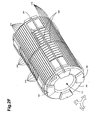
FIG. 2F illustrates a perspective view of a bobbin suitable for use in a multi-axial antenna system in accordance with some embodiments of the present invention. In these embodiments,bobbin 102 maybe a single element and may includelongitudal grooves 214 to accept the turns of section 114 (FIG. 2B ) of first coil 104 (FIG. 1 ),longitudal grooves 216 to accept turns of section 116 (FIG. 2D ) of second coil 106 (FIG. 1 ), andcircumferential grooves 218 to accept turns of third coil 108 (FIG. 1 ), although the scope of the invention is not limited in this respect. The use of the various grooves may allow the coils to be wound more accurately, which may provide additional dimensional stability to the coils under different environmental conditions, such as temperature, pressure and vibration. - In some embodiments,
bobbin 102 may also comprise thru-wire grooves 254 & 258 to allow the passage of thru wires 154 (FIG. 2E ) between the sections ofcoils 104 & 106 (FIG. 1 ). Thru-wire grooves 254 & 258 maybe deeper thanlongitudal grooves 214 & 216 and/orcircumferential grooves 218 as illustrated, although the scope of the invention is not limited in this respect. In some embodiments,grooves bobbin 102, although the scope of the invention is not limited in this respect. -
Bobbin 102 may allowcoils coils bobbin 102 may comprise an empty space suitable for a screen to help prevent the electromagnetic fields generated bycoils tool body 120. -
FIG. 3 is a functional block diagram of a subsurface measuring system for measuring subsurface formations in accordance with some embodiments of the present invention.Subsurface measuring system 300 maybe used for measuringsubsurface formations 310 belowsurface 309.Subsurface measuring system 300 may comprisedownhole tool 301 andsurface equipment 322.Downhole tool 301 may include transmittingantenna 302, receivingantenna 304, signal-generatingcircuitry 306 andsystem controller 308. Transmittingantenna system 302 may comprise at least two co-located coils wound around a torroidal-shaped bobbin. Signal generatingcircuitry 306 may provide signals to the coils of transmittingantenna system 302 to generate magnetic fields in mutually orthogonal directions. In some embodiments, a multi-axial antenna system, such as multi-axial antenna system 100 (FIG. 1 ) maybe suitable for use as transmittingantenna system 302 and/or receivingantenna system 304, although the scope of the invention is not limited in this respect. In these embodiments that employ separate antenna systems for transmitting and receiving, the transmitting and receivingantenna systems 302 & 304 may be located on adjacent portions oftool body 120 as illustrated inFIG. 3 , although this is not a requirement. - In some embodiments, signal-generating
circuitry 306 may provide currents with varying amplitudes and/or phases to the coils of transmittingantenna system 302 to generate magnetic vectors in angled directions to simulate a tilted-coil antenna system. In some other embodiments, signal-generatingcircuitry 306 may provide signals with shifted phases to the coils of transmittingantenna system 302 to generate a rotational magnetic field, although the scope of the invention not limited in this respect. During downhole operations,downhole tool 301 may be located ontool body 120 withinborehole 320. - In some embodiments, transmitting
antenna system 302 generates magnetic fields for incident onsubsurface formations 310 and receivingantenna system 304 may receive return magnetic fields fromsubsurface formations 310. In these embodiments,system controller 308 may process the return magnetic fields and may further provide control signals to signal-generatingcircuitry 306 for controlling the generation of incident magnetic fields by transmittingantenna system 302. - In some embodiments, transmitting
antenna system 302 may comprise first and second transmitting antenna coils. At least some of the turns of the first transmitting antenna coil may be connected in parallel and at least some of the turns of the second transmitting antenna coil may also be connected in parallel, although the scope of the invention not limited in this respect. In these embodiments, receivingantenna system 304 may also comprise first and second receiving antenna coils. The turns of the first receiving antenna coil may be connected in series and the turns of the second receiving antenna coil may also be connected in series, although the scope of the invention not limited in this respect. - Although
subsurface measuring system 300 is illustrated as having several separate functional elements, one or more of the functional elements may be combined and may be implemented by combinations of software-configured elements, such as processing elements including digital signal processors (DSPs), and/or other hardware elements. For example, some elements may comprise one or more microprocessors, DSPs, application-specific integrated circuits (ASICs), and combinations of various hardware and logic circuitry for performing at least the functions described herein. In some embodiments, the functional elements ofsubsurface measuring system 300 may refer to one or more processes operating on one or more processing elements. - The Abstract is provided to comply with 37 C.F.R. Section 1.72(b) requiring an abstract that will allow the reader to ascertain the nature and gist of the technical disclosure. It is submitted with the understanding that it will not be used to limit or interpret the scope or meaning of the claims. In the foregoing detailed description, various features are occasionally grouped together in a single embodiment for the purpose of streamlining the disclosure. This method of disclosure is not to be interpreted as reflecting an intention that the claimed embodiments of the subject matter require more features than are expressly recited in each claim. Rather, as the following claims reflect, invention may lie in less than all features of a single disclosed embodiment. Thus, the following claims are hereby incorporated into the detailed description, with each claim standing on its own as a separate preferred embodiment.
- In addition to the embodiments described previously and claimed in the appended claims, the following is a list of additional embodiments, which may serve as the basis for additional claims in this application or subsequent divisional applications.
- Embodiment 1: A multi-axial antenna system with co-located coils comprising: a first coil positioned around a portion of a toroidal-shaped bobbin through a central recess of the bobbin to generate a magnetic field in substantially a first direction when current flows through the first coil; a second coil positioned around a second portion of the bobbin through the central recess to generate a magnetic field in substantially a second direction when current flows through the second coil, the second direction being orthogonal to the first direction; and a third coil positioned longitudinally around the bobbin to generate a magnetic field in substantially a third direction when current flows through the third coil, the third direction being orthogonal to the first and second directions.
- Embodiment 2: The antenna system of
embodiment 1 wherein the central recess is provided to receive a tool body of a downhole tool, wherein the first and second directions are orthogonal to a tool axis, the tool axis being in the third direction, and wherein the first and second directions are in radial directions with respect to the toroidal-shaped bobbin. - Embodiment 3: The antenna system of
embodiment 1 wherein the first coil is positioned on the bobbin at approximately ninety-degrees with respect to the second coil, wherein the first and second coils are spaced apart on the bobbin, and wherein the third coil is wound longitudinally around the bobbin overlapping the first and second portions of the bobbin to provide three co-located antennas. - Embodiment 4: The antenna system of
embodiment 1 wherein the first coil comprises first and second sections provided on opposing sides of the bobbin to generate the magnetic field in the first direction when current flows through the first coil, and wherein the second coil comprises third and fourth sections provided on second opposing sides of the bobbin to generate the magnetic field in the second direction when current flows through the second coil. - Embodiment 5: The antenna system of embodiment 4 wherein the first, second and third coils comprise wire wound around the bobbin.
- Embodiment 6: The antenna system of embodiment 4 wherein at least one of the first, second and third coils comprises metal traces deposited on the bobbin.
- Embodiment 7: The antenna system of embodiment 4 further comprising: first thru-wires to electrically couple the first and second sections of the first coil; and second thru-wires to electrically couple the third and fourth sections of the second coil, wherein the first thru-wires form a twisted pair and couple the first and second sections in series, and wherein the second thru-wires form a twisted pair and couple the third and fourth sections in series.
- Embodiment 8: The antenna system of embodiment 4 further comprising: first thru-wires to electrically couple the first and second sections of the first coil; and second thru-wires to electrically couple the third and fourth sections of the second coil, wherein the first thru-wires form a twisted pair and couple the first and second sections in parallel, and wherein the second thru-wires form a twisted pair and couple the third and fourth sections in parallel.
- Embodiment 9: The antenna system of
embodiment 1 wherein the first and second coils are substantially identical in size and shape and are co-located in substantially the same longitudal position, and wherein the bobbin includes a plurality of grooves to accept windings of the coils. - Embodiment 10: The antenna system of
embodiment 1 wherein the bobbin comprises an electrically non-conductive material. - Embodiment 11: The antenna system of
embodiment 1 wherein the bobbin has a high-permeability (µr) core. - Embodiment 12: The antenna system of
embodiment 1 wherein signals are varied to the first, second and third coils to generate a magnetic field vector that is angled with respect to the first, second and third directions to simulate a tilted coil. - Embodiment 13: A subsurface measuring system for measuring subsurface formations comprising: an antenna system comprising at least two co-located coils positioned around a toroidal-shaped bobbin; and signal generating circuitry to provide signals to the coils to generate magnetic fields in mutually orthogonal directions
- Embodiment 14: The system of embodiment 13 wherein the signal-generating circuitry varies the signals to the coils to generate a magnetic field vector that is angled to simulate a tilted coil.
- Embodiment 15: The system of embodiment 13 wherein the signal-generating circuitry provides currents with shifted phases to the coils to generate a rotational magnetic field.
- Embodiment 16: The system of embodiment 13 wherein the signal-generating circuitry provides signals to the first, second and third coils in a time-shifted manner.
- Embodiment 17: The system of embodiment 13 wherein the antenna system is a transmitting antenna system to generate magnetic fields for incident on subsurface formations, and wherein the system further comprises a receiving antenna system to receive return magnetic fields from the subsurface formations.
- Embodiment 18: The system of embodiment 17 wherein the transmitting antenna system comprises first and second transmitting antenna coils, at least some turns of the first transmitting antenna coil being connected in parallel and at least some turns of the second transmitting antenna coil being connected in parallel, and wherein the receiving antenna system comprises first and second receiving antenna coils, turns of the first receiving antenna coil being connected in series and turns of the second receiving antenna coil being connected in series.
- Embodiment 19: The system of embodiment 13 wherein the antenna system comprises: a first coil positioned around a portion of the toroidal-shaped bobbin through a central recess of the bobbin to generate a magnetic field in substantially a first direction when current flows through the first coil; a second coil positioned around a second portion of the bobbin through the central recess to generate a magnetic field in substantially a second direction when current flows through the second coil, the second direction being orthogonal to the first direction; and a third coil positioned longitudinally around the bobbin to generate a magnetic field in substantially a third direction when current flows through the third coil, the third direction being orthogonal to the first and second directions.
- Embodiment 20: The system of embodiment 19 wherein the central recess receives a tool body of a downhole tool, wherein the first and second directions are orthogonal to a tool axis, the tool axis being in the third direction, and wherein the first and second directions are in orthogonal radial directions with respect to the toroidal-shaped bobbin.
- Embodiment 21: The system of embodiment 19 wherein the first coil is positioned on the bobbin at approximately ninety-degrees with respect to the second coil, wherein the first and second coils are spaced apart on the bobbin, and wherein the third coil is wound longitudinally around the bobbin overlapping the first and second portions of the bobbin to provide three co-located antennas having substantially co-located magnetic moment origins.
- Embodiment 22: The system of embodiment 19 wherein the first coil comprises first and second sections provided on opposing sides of the bobbin to generate the magnetic field in the first direction when current flows through the first coil, and wherein the second coil comprises third and fourth sections provided on second opposing sides of the bobbin to generate the magnetic field in the second direction when current flows through the second coil.
- Embodiment 23: A multi-axial antenna system comprising at least two co-located coils positioned around a toroidal-shaped bobbin, each coil to generate a magnetic field in a mutually orthogonal direction.
- Embodiment 24: The antenna system of embodiment 23 wherein the bobbin has a central recess, and wherein the plurality of co-located coils comprise at least two of: a first coil having first and second portions provided on opposing sides of the bobbin and through the central recess to generate a magnetic field in substantially a first direction when current flows through the first coil; a second coil having third and fourth portions provided on second opposing sides of the bobbin and through the central recess to generate a magnetic field in substantially a second direction when current flows through the second coil, the second direction being orthogonal to the first direction; and a third coil positioned longitudinally around the bobbin to generate a magnetic field in substantially a third direction when current flows through the third coil, the third direction being orthogonal to the first and second directions.
- Embodiment 25: The antenna system of embodiment 24 wherein the central recess is to receive a tool body of a downhole tool, wherein the first and second directions are orthogonal to a tool axis of the tool body, the tool axis being in the third direction, and wherein the first and second directions are in orthogonal radial directions with respect to the toroidal-shaped bobbin.
- Embodiment 26: The antenna system of embodiment 24 wherein the first coil is positioned on the bobbin at approximately ninety-degrees with respect to the second coil, wherein the first and second coils are spaced apart on the bobbin, and wherein the third coil is wound longitudinally around the bobbin overlapping the first and second portions of the bobbin to provide three co-located antennas.
- Embodiment 27: The antenna system of embodiment 23 wherein signals provided to the first, second and third coils are selected generate a magnetic field vector that is angled with respect to the first, second and third directions to simulate a tilted coil.
- Embodiment 28: A method for measuring subsurface formations comprising: providing signals to first, second and third coils to generate magnetic fields in mutually orthogonal directions, wherein at least two of the coils are co-located coils positioned around a toroidal-shaped bobbin.
- Embodiment 29: The method of embodiment 28 further comprising selecting the signals provided to the first, second and third coils to generate a magnetic field vector that is angled with respect to the first, second and third directions to simulate a tilted coil.
- Embodiment 30: The method of embodiment 28 further comprising providing the signals to the first, second and third coils in a time-shifted manner.
- Embodiment 31: The method of embodiment 28 further comprising providing currents with shifted phases to the first, second and third coils to generate a rotational magnetic field.
- Embodiment 32: The method of embodiment 29 wherein the first coil is wound around a portion of the toroidal-shaped bobbin through a central recess of the bobbin to generate a magnetic field in substantially a first direction when current flows through the first coil, wherein the second coil is wound around a second portion of the bobbin through the central recess to generate a magnetic field in substantially a second direction when current flows through the second coil, the second direction being orthogonal to the first direction, and wherein the third coil wound longitudinally around the bobbin to generate a magnetic field in substantially a third direction when current flows through the third coil, the third direction being orthogonal to the first and second directions.
Claims (14)
- A multi-axial antenna system with co-located coils comprising:a toroidal shaped bobbin that includes a first, a second, and a third set of grooves to receive coil windings;a first coil comprising opposite sections positioned around first opposite portions of the bobbin and through a central recess of the bobbin to generate a magnetic field in substantially a first direction when current flows through the first coil, windings of the first coil being received in respective grooves of the first set of grooves of the bobbin;a second coil comprising opposite sections positioned around second opposite portions of the bobbin and through the central recess to generate a magnetic field in substantially a second direction when current flows through the second coil, the second direction being orthogonal to the first direction, windings of the second coil being received in respective grooves of the second set of grooves of the bobbin; anda third coil around the bobbin to generate a magnetic field in substantially a third direction when current flows through the third coil, the third direction being orthogonal to the first and second directions, windings of the third coil being received in respective grooves of the third set of grooves of the bobbin.
- The antenna system of claim 1, wherein the central recess is provided to receive a tool body of a downhole tool,
wherein the first and second directions are orthogonal to a tool axis, the tool axis being in the third direction, and
wherein the first and second directions are in radial directions with respect to the toroidal-shaped bobbin. - The antenna system of claim 1, wherein the first coil is positioned on the bobbin at approximately ninety-degrees with respect to the second coil,
wherein the first and second coils are spaced apart on the bobbin, and
wherein the third coil is wound circumferentially around the bobbin, the third coil overlapping the first and second portions of the bobbin to provide three co-located antennas. - The antenna system of claim 1, wherein the first and second coils are substantially identical in size and shape and are co-located in substantially the same longitudinal position.
- The antenna system of claim 1, wherein the first, second, and third sets of grooves of the bobbin are configured to allow the first, second, and third coils to be co-located and to be wound without spatial interference between their windings.
- The antenna system of claim 1, wherein in the first, second, and third coils are colocated such that respective magnetic moments of the first, second, and third coils have respective origins that are located substantially at the same point
- The antenna system of claim 1, wherein the first and second set of grooves of the bobbin are longitudinal grooves.
- The antenna system of claim 7, wherein the longitudinal grooves are milled on a surface of the bobbin.
- The antenna system of claim 8, wherein the longitudinal grooves extend along substantially the whole length of the bobbin.
- The antenna system of claim 7, wherein the third set of grooves of the bobbin are circumferential grooves.
- The antenna system of claim 10, wherein the circumferential grooves are milled on a surface of the bobbin.
- The antenna system of claim 1, wherein the bobbin further defines thru-wire grooves that allow the passage of thru-wires between the opposite sections of the first coil and between the opposite sections of the second coil.
- The antenna system of claim 13, wherein:the first and second set of grooves of the bobbin are longitudinal grooves;the third set of grooves of the bobbin are circumferential grooves;the first, second and third set of grooves are milled on a surface of the bobbin;the thru-wire grooves are milled on the surface of the bobbin; andthe thru-wire grooves are deeper than at least one of the longitudinal grooves and the circumferential grooves.
- The antenna system of claim 1, wherein a first thru-wire couples the opposite sections of the first coil in parallel and a second thru-wire couples the opposition sections of the second coil in parallel.
Priority Applications (1)
| Application Number | Priority Date | Filing Date | Title |
|---|---|---|---|
| EP20140181867 EP2824760A1 (en) | 2006-09-15 | 2006-09-15 | Multi-axial antenna and method for use in downhole tools |
Applications Claiming Priority (3)
| Application Number | Priority Date | Filing Date | Title |
|---|---|---|---|
| EP06803663.1A EP2052436B1 (en) | 2006-09-15 | 2006-09-15 | Multi-axial antenna and method for use in downhole tools |
| EP20140181867 EP2824760A1 (en) | 2006-09-15 | 2006-09-15 | Multi-axial antenna and method for use in downhole tools |
| PCT/US2006/036009 WO2008036077A2 (en) | 2006-09-15 | 2006-09-15 | Multi-axial antenna and method for use in downhole tools |
Related Parent Applications (2)
| Application Number | Title | Priority Date | Filing Date |
|---|---|---|---|
| EP06803663.1A Division-Into EP2052436B1 (en) | 2006-09-15 | 2006-09-15 | Multi-axial antenna and method for use in downhole tools |
| EP06803663.1A Division EP2052436B1 (en) | 2006-09-15 | 2006-09-15 | Multi-axial antenna and method for use in downhole tools |
Publications (1)
| Publication Number | Publication Date |
|---|---|
| EP2824760A1 true EP2824760A1 (en) | 2015-01-14 |
Family
ID=39201006
Family Applications (2)
| Application Number | Title | Priority Date | Filing Date |
|---|---|---|---|
| EP06803663.1A Expired - Fee Related EP2052436B1 (en) | 2006-09-15 | 2006-09-15 | Multi-axial antenna and method for use in downhole tools |
| EP20140181867 Withdrawn EP2824760A1 (en) | 2006-09-15 | 2006-09-15 | Multi-axial antenna and method for use in downhole tools |
Family Applications Before (1)
| Application Number | Title | Priority Date | Filing Date |
|---|---|---|---|
| EP06803663.1A Expired - Fee Related EP2052436B1 (en) | 2006-09-15 | 2006-09-15 | Multi-axial antenna and method for use in downhole tools |
Country Status (5)
| Country | Link |
|---|---|
| US (3) | US8471562B2 (en) |
| EP (2) | EP2052436B1 (en) |
| CN (1) | CN101536252B (en) |
| CA (1) | CA2627979C (en) |
| WO (1) | WO2008036077A2 (en) |
Families Citing this family (73)
| Publication number | Priority date | Publication date | Assignee | Title |
|---|---|---|---|---|
| CN101536252B (en) | 2006-09-15 | 2012-12-05 | 哈里伯顿能源服务公司 | Multi-axis antennas and methods for downhole appliances |
| US7816921B2 (en) * | 2006-09-20 | 2010-10-19 | Baker Hughes Incorporated | Resistivity tools with load-bearing azimuthally sensitive antennas and methods of using same |
| US8274289B2 (en) | 2006-12-15 | 2012-09-25 | Halliburton Energy Services, Inc. | Antenna coupling component measurement tool having rotating antenna configuration |
| US9121967B2 (en) | 2007-08-31 | 2015-09-01 | Baker Hughes Incorporated | Method and apparatus for well-bore proximity measurement while drilling |
| AU2008348131B2 (en) | 2008-01-18 | 2011-08-04 | Halliburton Energy Services, Inc. | EM-guided drilling relative to an existing borehole |
| US8749243B2 (en) | 2010-06-22 | 2014-06-10 | Halliburton Energy Services, Inc. | Real time determination of casing location and distance with tilted antenna measurement |
| US8844648B2 (en) | 2010-06-22 | 2014-09-30 | Halliburton Energy Services, Inc. | System and method for EM ranging in oil-based mud |
| US9115569B2 (en) | 2010-06-22 | 2015-08-25 | Halliburton Energy Services, Inc. | Real-time casing detection using tilted and crossed antenna measurement |
| US8917094B2 (en) | 2010-06-22 | 2014-12-23 | Halliburton Energy Services, Inc. | Method and apparatus for detecting deep conductive pipe |
| GB2481493B (en) * | 2010-06-22 | 2013-01-23 | Halliburton Energy Serv Inc | Methods and apparatus for detecting deep conductive pipe |
| US9360582B2 (en) | 2010-07-02 | 2016-06-07 | Halliburton Energy Services, Inc. | Correcting for magnetic interference in azimuthal tool measurements |
| US8704721B2 (en) | 2011-08-08 | 2014-04-22 | Rf Technologies, Inc. | Multi-axial resonant ferrite core antenna |
| AU2011374874B2 (en) * | 2011-08-10 | 2015-04-16 | Halliburton Energy Services, Inc. | Coil winding methods for downhole logging tools |
| US9638824B2 (en) * | 2011-11-14 | 2017-05-02 | SeeScan, Inc. | Quad-gradient coils for use in locating systems |
| US9075157B2 (en) * | 2012-02-24 | 2015-07-07 | Baker Hughes Incorporated | Bending correction for deep reading azimuthal propagation resistivity |
| US10376845B2 (en) | 2016-04-14 | 2019-08-13 | Lockheed Martin Corporation | Membranes with tunable selectivity |
| US10653824B2 (en) | 2012-05-25 | 2020-05-19 | Lockheed Martin Corporation | Two-dimensional materials and uses thereof |
| US9151150B2 (en) * | 2012-10-23 | 2015-10-06 | Baker Hughes Incorporated | Apparatus and methods for well-bore proximity measurement while drilling |
| CN102904005A (en) * | 2012-10-29 | 2013-01-30 | 中国石油天然气股份有限公司 | An underground signal receiving antenna and its manufacturing method |
| US9863237B2 (en) * | 2012-11-26 | 2018-01-09 | Baker Hughes, A Ge Company, Llc | Electromagnetic telemetry apparatus and methods for use in wellbore applications |
| TW201504140A (en) | 2013-03-12 | 2015-02-01 | Lockheed Corp | Method for forming perforated graphene with uniform aperture size |
| US9480415B2 (en) | 2013-04-26 | 2016-11-01 | Medtronic Navigation, Inc. | Electromagnetic coil apparatuses for surgical navigation and corresponding methods |
| US9482631B2 (en) | 2013-05-14 | 2016-11-01 | Chevron U.S.A. Inc. | Formation core sample holder assembly and testing method for nuclear magnetic resonance measurements |
| WO2014201297A2 (en) * | 2013-06-12 | 2014-12-18 | Well Resolutions Technology | Apparatus and methods for making azimuthal resistivity measurements |
| US9572918B2 (en) | 2013-06-21 | 2017-02-21 | Lockheed Martin Corporation | Graphene-based filter for isolating a substance from blood |
| US9964660B2 (en) | 2013-07-15 | 2018-05-08 | Baker Hughes, A Ge Company, Llc | Electromagnetic telemetry apparatus and methods for use in wellbores |
| DE102013217555B3 (en) * | 2013-09-03 | 2014-12-04 | Siemens Aktiengesellschaft | Combined shim and RF coil elements |
| US9880307B2 (en) | 2013-10-24 | 2018-01-30 | Baker Hughes Incorporated | Induction logging sensor |
| WO2015072985A1 (en) | 2013-11-13 | 2015-05-21 | Halliburton Energy Services, Inc. | Dual antenna for circular polarization |
| US9831925B2 (en) | 2014-01-20 | 2017-11-28 | Raytheon Company | High efficiency polarized ULF/VLF/RF transciever antenna |
| CN106029596A (en) | 2014-01-31 | 2016-10-12 | 洛克希德马丁公司 | Processes for forming composite structures with a two-dimensional material using a porous, non-sacrificial supporting layer |
| US10830039B2 (en) * | 2014-04-03 | 2020-11-10 | Baker Hughes Holdings Llc | Downhole tri-axial induction electromagnetic tool |
| CN103926625B (en) * | 2014-04-18 | 2016-09-14 | 哈尔滨工程大学 | One utilizes geomagnetic total field to the remote localization method of magnetic target with high precision under water |
| MX2016013317A (en) | 2014-05-06 | 2017-01-18 | Halliburton Energy Services Inc | Front tangential antenna for nuclear magnetic resonance (nmr) well logging. |
| MX362081B (en) | 2014-07-11 | 2019-01-07 | Halliburton Energy Services Inc | Deep azimuthal inspection of wellbore pipes. |
| JP6437227B2 (en) * | 2014-07-18 | 2018-12-12 | 株式会社ヨコオ | In-vehicle antenna device |
| DE102014218874A1 (en) * | 2014-09-19 | 2016-03-24 | Forschungszentrum Jülich GmbH | High quality coil |
| AU2014411434B2 (en) | 2014-11-13 | 2017-12-07 | Halliburton Energy Services, Inc. | Resistivity logging tools with tilted ferrite elements for azimuthal sensitivity |
| US9851315B2 (en) | 2014-12-11 | 2017-12-26 | Chevron U.S.A. Inc. | Methods for quantitative characterization of asphaltenes in solutions using two-dimensional low-field NMR measurement |
| RU2579177C1 (en) * | 2015-01-14 | 2016-04-10 | Открытое акционерное общество "Нефтяная компания "Роснефть" | Device for generation of electromagnetic field of toroidal coil in geological environment |
| RU2578774C1 (en) * | 2015-01-14 | 2016-03-27 | Открытое акционерное общество "Нефтяная компания "Роснефть" | Device for detecting electromagnetic field characteristics using toroidal coils |
| MY182545A (en) * | 2015-01-16 | 2021-01-25 | Halliburton Energy Services Inc | Collar-mountable bobbin antenna having coil and ferrite slots |
| US11096605B2 (en) | 2015-03-31 | 2021-08-24 | Medtronic Navigation, Inc. | Modular coil assembly |
| CA2985342C (en) | 2015-06-26 | 2020-04-21 | Halliburton Energy Services, Inc. | Antennas for wellbore logging tools and methods of manufacture |
| AU2015400159A1 (en) | 2015-06-26 | 2017-11-09 | Halliburton Energy Services, Inc. | Antennas for wellbore logging tools and methods of manufacture |
| GB2554594B (en) * | 2015-07-27 | 2021-08-04 | Halliburton Energy Services Inc | Tilted antenna bobbins and methods of manufacture |
| JP2018528144A (en) | 2015-08-05 | 2018-09-27 | ロッキード・マーチン・コーポレーション | Perforable sheet of graphene-based material |
| WO2017023377A1 (en) | 2015-08-06 | 2017-02-09 | Lockheed Martin Corporation | Nanoparticle modification and perforation of graphene |
| WO2017069742A1 (en) | 2015-10-20 | 2017-04-27 | Halliburton Energy Services, Inc. | Soft magnetic bands for tilted coil antennas |
| KR102543530B1 (en) * | 2016-03-10 | 2023-06-15 | 현대모비스 주식회사 | Vehicle door system and operating method thereof |
| US10634746B2 (en) | 2016-03-29 | 2020-04-28 | Chevron U.S.A. Inc. | NMR measured pore fluid phase behavior measurements |
| EP3442697A4 (en) | 2016-04-14 | 2020-03-18 | Lockheed Martin Corporation | Selective interfacial mitigation of graphene defects |
| WO2017180134A1 (en) | 2016-04-14 | 2017-10-19 | Lockheed Martin Corporation | Methods for in vivo and in vitro use of graphene and other two-dimensional materials |
| KR20180133430A (en) * | 2016-04-14 | 2018-12-14 | 록히드 마틴 코포레이션 | Method for in situ monitoring and control of defect formation or healing |
| EP3442786A4 (en) | 2016-04-14 | 2020-03-18 | Lockheed Martin Corporation | Two-dimensional membrane structures having flow passages |
| WO2018118255A1 (en) * | 2016-12-22 | 2018-06-28 | Halliburton Energy Services, Inc. | Single layer antenna path profile |
| EP3516167B1 (en) * | 2016-12-22 | 2023-08-30 | Halliburton Energy Services, Inc. | Insulator base for antenna assemblies |
| US11125073B2 (en) * | 2017-01-27 | 2021-09-21 | Halliburton Energy Services, Inc. | Hybrid axial and radial receiver configurations for electromagnetic ranging systems |
| CA3046919C (en) | 2017-01-31 | 2023-03-07 | Halliburton Energy Services, Inc. | Optimization of ranging measurements |
| US10737099B2 (en) | 2017-05-17 | 2020-08-11 | Medtronic, Inc. | Antenna for implantable medical devices |
| US10466320B2 (en) * | 2017-08-17 | 2019-11-05 | General Electric Company | Multi-layered radio frequency coil |
| WO2019168555A1 (en) * | 2018-03-02 | 2019-09-06 | Halliburton Energy Services, Inc. | Parallel coil paths for downhole antennas |
| US11332991B2 (en) | 2019-07-17 | 2022-05-17 | Saudi Arabian Oil Company | Targeted downhole delivery with container |
| CN110534284B (en) * | 2019-07-17 | 2022-05-06 | 中国石油天然气集团有限公司 | Inductive imaging combined three-axis coil |
| US11879328B2 (en) | 2021-08-05 | 2024-01-23 | Saudi Arabian Oil Company | Semi-permanent downhole sensor tool |
| US11867049B1 (en) | 2022-07-19 | 2024-01-09 | Saudi Arabian Oil Company | Downhole logging tool |
| US11913329B1 (en) | 2022-09-21 | 2024-02-27 | Saudi Arabian Oil Company | Untethered logging devices and related methods of logging a wellbore |
| US12038550B2 (en) * | 2022-12-08 | 2024-07-16 | Halliburton Energy Services, Inc. | Nuclear magnetic resonance antenna packing |
| US11931255B1 (en) | 2023-08-18 | 2024-03-19 | E-Valve Systems Ltd. | Prosthetic aortic valve pacing systems |
| US11975203B1 (en) | 2023-08-18 | 2024-05-07 | E-Valve Systems Ltd. | Prosthetic aortic valve pacing systems |
| US12486762B2 (en) | 2024-01-11 | 2025-12-02 | Saudi Arabian Oil Company | Systems and methods for untethered wellbore investigation using modular autonomous device |
| US20250250894A1 (en) * | 2024-02-05 | 2025-08-07 | Halliburton Energy Services, Inc. | Conformal space filling coils |
| US12605553B1 (en) | 2025-02-19 | 2026-04-21 | Smartvalves Ltd | In situ assembly of prosthetic pacing valves |
Citations (5)
| Publication number | Priority date | Publication date | Assignee | Title |
|---|---|---|---|---|
| DE3735585A1 (en) * | 1986-10-23 | 1988-04-28 | Radiodetection Ltd | POSITION DISPLAY SYSTEM |
| WO2000050926A1 (en) * | 1999-02-22 | 2000-08-31 | Halliburton Energy Services, Inc. | Directional resistivity measurements for azimuthal proximity detection of bed boundaries |
| GB2387033A (en) * | 2002-03-29 | 2003-10-01 | Schlumberger Holdings | Antenna structure for well logging tools |
| WO2003100466A1 (en) * | 2002-05-20 | 2003-12-04 | Halliburton Energy Services, Inc. | Induction well logging apparatus and method |
| US20040017197A1 (en) * | 2002-07-29 | 2004-01-29 | Schlumberger Technology Corporation | Co-located antennas |
Family Cites Families (34)
| Publication number | Priority date | Publication date | Assignee | Title |
|---|---|---|---|---|
| US3092800A (en) * | 1960-08-04 | 1963-06-04 | Constantine A Michalos | Electrical resistor |
| US3800213A (en) * | 1972-10-24 | 1974-03-26 | Develco | Three axis toroidal fluxgate type magnetic sensor |
| US4063207A (en) | 1977-01-31 | 1977-12-13 | Litton Systems, Inc. | Coil structure |
| US4418570A (en) | 1981-12-08 | 1983-12-06 | Exxon Production Research Co. | Ice thickness inductor probe |
| FR2586300B1 (en) | 1985-08-13 | 1987-10-23 | Commissariat Energie Atomique | METHOD FOR PRODUCING LOW-DIMENSIONAL TORIC WINDING AND OPTIMAL GEOMETRY |
| SU1377803A1 (en) | 1986-01-06 | 1988-02-28 | Краснодарский Филиал Научно-Исследовательского Института Морской Геофизики Всесоюзного Морского Научно-Производственного Геолого-Геофизического Объединения По Разведке Нефти И Газа "Союзморгео" | Inductive transducer |
| US4834193A (en) * | 1987-12-22 | 1989-05-30 | Gas Research Institute | Earth boring apparatus and method with control valve |
| US4907658A (en) * | 1988-09-29 | 1990-03-13 | Gas Research Institute | Percussive mole boring device with electronic transmitter |
| US4958689A (en) * | 1988-12-30 | 1990-09-25 | Gas Research Institute | Method of providing a high pressure surge of working fluid to an underground percussive mole |
| US4945999A (en) * | 1989-04-06 | 1990-08-07 | The Charles Machine Works, Inc. | Directional rod pusher |
| US5070948A (en) * | 1989-04-06 | 1991-12-10 | The Charles Machine Works, Inc. | Directional rod pusher |
| NL9100247A (en) * | 1991-02-13 | 1992-09-01 | Philips Nv | TRANSFORMER. |
| SE9102122D0 (en) | 1991-07-08 | 1991-07-08 | Skf Nova Ab | SENSOR RESPECTIVE PROCEDURE BEFORE SEATING TORQUE AND / OR FORCES |
| US5390349A (en) * | 1992-08-26 | 1995-02-14 | Synergy Microwave Corporation | Plural transformers with elongated cores |
| JPH076919A (en) * | 1992-09-08 | 1995-01-10 | Kenichi Suzuki | Magnetic core |
| US5672967A (en) | 1995-09-19 | 1997-09-30 | Southwest Research Institute | Compact tri-axial fluxgate magnetometer and housing with unitary orthogonal sensor substrate |
| US5757186A (en) | 1996-02-23 | 1998-05-26 | Western Atlas International, Inc. | Nuclear magnetic resonance well logging apparatus and method adapted for measurement-while-drilling |
| US5781160A (en) * | 1996-05-31 | 1998-07-14 | The Ohio State University | Independently fed AM/FM heated window antenna |
| US6166543A (en) * | 1997-09-25 | 2000-12-26 | Schlumberger Technology Corporation | Method and apparatus for measuring nuclear magnetic resonance |
| US5942990A (en) | 1997-10-24 | 1999-08-24 | Halliburton Energy Services, Inc. | Electromagnetic signal repeater and method for use of same |
| US6246236B1 (en) | 1998-03-03 | 2001-06-12 | Schlumberger Technology Corporation | Apparatus and method for obtaining a nuclear magnetic resonance measurement while drilling |
| AU737283B2 (en) | 1998-07-30 | 2001-08-16 | Schlumberger Holdings Limited | Nuclear magnetic resonance logging with azimuthal resolution using gradient coils |
| US6118193A (en) * | 1998-10-13 | 2000-09-12 | Morris; Richard M. | Electromagnetic machine for providing a propulsive force |
| US6476609B1 (en) * | 1999-01-28 | 2002-11-05 | Dresser Industries, Inc. | Electromagnetic wave resistivity tool having a tilted antenna for geosteering within a desired payzone |
| US6459262B1 (en) * | 2000-04-25 | 2002-10-01 | Baker Hughes Incorporated | Toroidal receiver for NMR MWD |
| US6563474B2 (en) * | 2000-12-21 | 2003-05-13 | Lear Corporation | Remote access device having multiple inductive coil antenna |
| US6930652B2 (en) * | 2002-03-29 | 2005-08-16 | Schlumberger Technology Corporation | Simplified antenna structures for logging tools |
| EP1642156B1 (en) | 2003-05-02 | 2020-03-04 | Halliburton Energy Services, Inc. | Systems and methods for nmr logging |
| US7286091B2 (en) * | 2003-06-13 | 2007-10-23 | Schlumberger Technology Corporation | Co-located antennas |
| US8432167B2 (en) * | 2004-02-09 | 2013-04-30 | Baker Hughes Incorporated | Method and apparatus of using magnetic material with residual magnetization in transient electromagnetic measurement |
| US7295168B2 (en) * | 2004-05-20 | 2007-11-13 | Yonezawa Electric Wire Co., Ltd. | Antenna coil |
| US7786733B2 (en) * | 2004-07-14 | 2010-08-31 | Schlumberger Technology Corporation | Apparatus and system for well placement and reservoir characterization |
| US7916092B2 (en) * | 2006-08-02 | 2011-03-29 | Schlumberger Technology Corporation | Flexible circuit for downhole antenna |
| CN101536252B (en) | 2006-09-15 | 2012-12-05 | 哈里伯顿能源服务公司 | Multi-axis antennas and methods for downhole appliances |
-
2006
- 2006-09-15 CN CN2006800558295A patent/CN101536252B/en not_active Expired - Fee Related
- 2006-09-15 CA CA 2627979 patent/CA2627979C/en not_active Expired - Fee Related
- 2006-09-15 EP EP06803663.1A patent/EP2052436B1/en not_active Expired - Fee Related
- 2006-09-15 WO PCT/US2006/036009 patent/WO2008036077A2/en not_active Ceased
- 2006-09-15 US US12/095,692 patent/US8471562B2/en active Active
- 2006-09-15 EP EP20140181867 patent/EP2824760A1/en not_active Withdrawn
-
2013
- 2013-05-16 US US13/895,881 patent/US9121960B2/en active Active
-
2015
- 2015-07-28 US US14/811,242 patent/US9632201B2/en active Active
Patent Citations (5)
| Publication number | Priority date | Publication date | Assignee | Title |
|---|---|---|---|---|
| DE3735585A1 (en) * | 1986-10-23 | 1988-04-28 | Radiodetection Ltd | POSITION DISPLAY SYSTEM |
| WO2000050926A1 (en) * | 1999-02-22 | 2000-08-31 | Halliburton Energy Services, Inc. | Directional resistivity measurements for azimuthal proximity detection of bed boundaries |
| GB2387033A (en) * | 2002-03-29 | 2003-10-01 | Schlumberger Holdings | Antenna structure for well logging tools |
| WO2003100466A1 (en) * | 2002-05-20 | 2003-12-04 | Halliburton Energy Services, Inc. | Induction well logging apparatus and method |
| US20040017197A1 (en) * | 2002-07-29 | 2004-01-29 | Schlumberger Technology Corporation | Co-located antennas |
Also Published As
| Publication number | Publication date |
|---|---|
| US8471562B2 (en) | 2013-06-25 |
| CN101536252B (en) | 2012-12-05 |
| US20130249561A1 (en) | 2013-09-26 |
| WO2008036077A3 (en) | 2008-09-25 |
| US20150331137A1 (en) | 2015-11-19 |
| EP2052436A2 (en) | 2009-04-29 |
| CN101536252A (en) | 2009-09-16 |
| US9632201B2 (en) | 2017-04-25 |
| CA2627979C (en) | 2013-08-13 |
| WO2008036077A2 (en) | 2008-03-27 |
| EP2052436B1 (en) | 2014-10-29 |
| EP2052436A4 (en) | 2010-05-19 |
| CA2627979A1 (en) | 2008-03-27 |
| US20090302847A1 (en) | 2009-12-10 |
| WO2008036077B1 (en) | 2008-11-06 |
| US9121960B2 (en) | 2015-09-01 |
Similar Documents
| Publication | Publication Date | Title |
|---|---|---|
| US9632201B2 (en) | Multi-axial antenna and method for use in downhole tools | |
| CA2434435C (en) | Co-located antennas | |
| JP5498593B2 (en) | Multi-current devices for magnetic resonance radio frequency coils | |
| AU754752B2 (en) | Shield apparatus for use in conjunction with a well tool and method for shielding a coil | |
| US6373248B1 (en) | Nuclear magnetic resonance logging with azimuthal resolution | |
| US20060043973A1 (en) | Co-located antennas | |
| US20100244841A1 (en) | Non-planar antennae for directional resistivity logging | |
| US8786287B2 (en) | Collocated tri-axial induction sensors with segmented horizontal coils | |
| WO2008061114A2 (en) | Multipole antennae for logging-while-drilling resistivity measurements | |
| GB2514467A (en) | Actively shielded, cylindrical gradient coil system with passive RF shielding for NMR devices | |
| US5680044A (en) | Oscillating magnetic field generating assembly | |
| RU2337436C2 (en) | Improved logging antennae based on nuclear magnetic resonance | |
| JPH1090385A (en) | Rf coil assembly | |
| CN102928888A (en) | Multi-axis antenna and method for downhole tool | |
| AU2002318890B2 (en) | Shield apparatus for use in conjunction with a well tool and method for shielding a coil | |
| US8395388B2 (en) | Circumferentially spaced magnetic field generating devices |
Legal Events
| Date | Code | Title | Description |
|---|---|---|---|
| 17P | Request for examination filed |
Effective date: 20140821 |
|
| AC | Divisional application: reference to earlier application |
Ref document number: 2052436 Country of ref document: EP Kind code of ref document: P |
|
| AK | Designated contracting states |
Kind code of ref document: A1 Designated state(s): DE FR GB |
|
| PUAI | Public reference made under article 153(3) epc to a published international application that has entered the european phase |
Free format text: ORIGINAL CODE: 0009012 |
|
| RIN1 | Information on inventor provided before grant (corrected) |
Inventor name: KNIZHNIK, SERGEY |
|
| R17P | Request for examination filed (corrected) |
Effective date: 20150710 |
|
| RBV | Designated contracting states (corrected) |
Designated state(s): DE FR GB |
|
| STAA | Information on the status of an ep patent application or granted ep patent |
Free format text: STATUS: THE APPLICATION HAS BEEN WITHDRAWN |
|
| 18W | Application withdrawn |
Effective date: 20151112 |