EP2824730A2 - Battery Pack - Google Patents
Battery Pack Download PDFInfo
- Publication number
- EP2824730A2 EP2824730A2 EP20130194977 EP13194977A EP2824730A2 EP 2824730 A2 EP2824730 A2 EP 2824730A2 EP 20130194977 EP20130194977 EP 20130194977 EP 13194977 A EP13194977 A EP 13194977A EP 2824730 A2 EP2824730 A2 EP 2824730A2
- Authority
- EP
- European Patent Office
- Prior art keywords
- terminal
- cap plate
- battery pack
- circuit module
- protection circuit
- Prior art date
- Legal status (The legal status is an assumption and is not a legal conclusion. Google has not performed a legal analysis and makes no representation as to the accuracy of the status listed.)
- Granted
Links
Images


Classifications
-
- H—ELECTRICITY
- H01—ELECTRIC ELEMENTS
- H01M—PROCESSES OR MEANS, e.g. BATTERIES, FOR THE DIRECT CONVERSION OF CHEMICAL ENERGY INTO ELECTRICAL ENERGY
- H01M10/00—Secondary cells; Manufacture thereof
- H01M10/42—Methods or arrangements for servicing or maintenance of secondary cells or secondary half-cells
- H01M10/425—Structural combination with electronic components, e.g. electronic circuits integrated to the outside of the casing
-
- H—ELECTRICITY
- H01—ELECTRIC ELEMENTS
- H01M—PROCESSES OR MEANS, e.g. BATTERIES, FOR THE DIRECT CONVERSION OF CHEMICAL ENERGY INTO ELECTRICAL ENERGY
- H01M50/00—Constructional details or processes of manufacture of the non-active parts of electrochemical cells other than fuel cells, e.g. hybrid cells
- H01M50/20—Mountings; Secondary casings or frames; Racks, modules or packs; Suspension devices; Shock absorbers; Transport or carrying devices; Holders
- H01M50/204—Racks, modules or packs for multiple batteries or multiple cells
- H01M50/207—Racks, modules or packs for multiple batteries or multiple cells characterised by their shape
- H01M50/209—Racks, modules or packs for multiple batteries or multiple cells characterised by their shape adapted for prismatic or rectangular cells
-
- H—ELECTRICITY
- H01—ELECTRIC ELEMENTS
- H01M—PROCESSES OR MEANS, e.g. BATTERIES, FOR THE DIRECT CONVERSION OF CHEMICAL ENERGY INTO ELECTRICAL ENERGY
- H01M50/00—Constructional details or processes of manufacture of the non-active parts of electrochemical cells other than fuel cells, e.g. hybrid cells
- H01M50/50—Current conducting connections for cells or batteries
- H01M50/502—Interconnectors for connecting terminals of adjacent batteries; Interconnectors for connecting cells outside a battery casing
- H01M50/503—Interconnectors for connecting terminals of adjacent batteries; Interconnectors for connecting cells outside a battery casing characterised by the shape of the interconnectors
-
- H—ELECTRICITY
- H01—ELECTRIC ELEMENTS
- H01M—PROCESSES OR MEANS, e.g. BATTERIES, FOR THE DIRECT CONVERSION OF CHEMICAL ENERGY INTO ELECTRICAL ENERGY
- H01M50/00—Constructional details or processes of manufacture of the non-active parts of electrochemical cells other than fuel cells, e.g. hybrid cells
- H01M50/50—Current conducting connections for cells or batteries
- H01M50/502—Interconnectors for connecting terminals of adjacent batteries; Interconnectors for connecting cells outside a battery casing
- H01M50/519—Interconnectors for connecting terminals of adjacent batteries; Interconnectors for connecting cells outside a battery casing comprising printed circuit boards [PCB]
-
- H—ELECTRICITY
- H01—ELECTRIC ELEMENTS
- H01M—PROCESSES OR MEANS, e.g. BATTERIES, FOR THE DIRECT CONVERSION OF CHEMICAL ENERGY INTO ELECTRICAL ENERGY
- H01M50/00—Constructional details or processes of manufacture of the non-active parts of electrochemical cells other than fuel cells, e.g. hybrid cells
- H01M50/50—Current conducting connections for cells or batteries
- H01M50/543—Terminals
- H01M50/547—Terminals characterised by the disposition of the terminals on the cells
- H01M50/55—Terminals characterised by the disposition of the terminals on the cells on the same side of the cell
-
- H—ELECTRICITY
- H01—ELECTRIC ELEMENTS
- H01M—PROCESSES OR MEANS, e.g. BATTERIES, FOR THE DIRECT CONVERSION OF CHEMICAL ENERGY INTO ELECTRICAL ENERGY
- H01M50/00—Constructional details or processes of manufacture of the non-active parts of electrochemical cells other than fuel cells, e.g. hybrid cells
- H01M50/50—Current conducting connections for cells or batteries
- H01M50/543—Terminals
- H01M50/552—Terminals characterised by their shape
- H01M50/553—Terminals adapted for prismatic, pouch or rectangular cells
-
- H—ELECTRICITY
- H01—ELECTRIC ELEMENTS
- H01M—PROCESSES OR MEANS, e.g. BATTERIES, FOR THE DIRECT CONVERSION OF CHEMICAL ENERGY INTO ELECTRICAL ENERGY
- H01M50/00—Constructional details or processes of manufacture of the non-active parts of electrochemical cells other than fuel cells, e.g. hybrid cells
- H01M50/50—Current conducting connections for cells or batteries
- H01M50/572—Means for preventing undesired use or discharge
-
- H—ELECTRICITY
- H01—ELECTRIC ELEMENTS
- H01M—PROCESSES OR MEANS, e.g. BATTERIES, FOR THE DIRECT CONVERSION OF CHEMICAL ENERGY INTO ELECTRICAL ENERGY
- H01M10/00—Secondary cells; Manufacture thereof
- H01M10/42—Methods or arrangements for servicing or maintenance of secondary cells or secondary half-cells
- H01M10/425—Structural combination with electronic components, e.g. electronic circuits integrated to the outside of the casing
- H01M2010/4271—Battery management systems including electronic circuits, e.g. control of current or voltage to keep battery in healthy state, cell balancing
-
- H—ELECTRICITY
- H01—ELECTRIC ELEMENTS
- H01M—PROCESSES OR MEANS, e.g. BATTERIES, FOR THE DIRECT CONVERSION OF CHEMICAL ENERGY INTO ELECTRICAL ENERGY
- H01M2200/00—Safety devices for primary or secondary batteries
-
- H—ELECTRICITY
- H01—ELECTRIC ELEMENTS
- H01M—PROCESSES OR MEANS, e.g. BATTERIES, FOR THE DIRECT CONVERSION OF CHEMICAL ENERGY INTO ELECTRICAL ENERGY
- H01M2220/00—Batteries for particular applications
- H01M2220/30—Batteries in portable systems, e.g. mobile phone, laptop
-
- H—ELECTRICITY
- H01—ELECTRIC ELEMENTS
- H01M—PROCESSES OR MEANS, e.g. BATTERIES, FOR THE DIRECT CONVERSION OF CHEMICAL ENERGY INTO ELECTRICAL ENERGY
- H01M50/00—Constructional details or processes of manufacture of the non-active parts of electrochemical cells other than fuel cells, e.g. hybrid cells
- H01M50/50—Current conducting connections for cells or batteries
- H01M50/572—Means for preventing undesired use or discharge
- H01M50/574—Devices or arrangements for the interruption of current
- H01M50/581—Devices or arrangements for the interruption of current in response to temperature
-
- Y—GENERAL TAGGING OF NEW TECHNOLOGICAL DEVELOPMENTS; GENERAL TAGGING OF CROSS-SECTIONAL TECHNOLOGIES SPANNING OVER SEVERAL SECTIONS OF THE IPC; TECHNICAL SUBJECTS COVERED BY FORMER USPC CROSS-REFERENCE ART COLLECTIONS [XRACs] AND DIGESTS
- Y02—TECHNOLOGIES OR APPLICATIONS FOR MITIGATION OR ADAPTATION AGAINST CLIMATE CHANGE
- Y02E—REDUCTION OF GREENHOUSE GAS [GHG] EMISSIONS, RELATED TO ENERGY GENERATION, TRANSMISSION OR DISTRIBUTION
- Y02E60/00—Enabling technologies; Technologies with a potential or indirect contribution to GHG emissions mitigation
- Y02E60/10—Energy storage using batteries
Definitions
- the present invention relates to a battery pack.
- a portable computer may include an internal battery pack in order to be used in various places without being affected by a power supply device.
- the internal battery pack may include unit batteries that may be repeatedly re-charged/discharged.
- the present invention relates to a structure of a battery pack.
- the present invention provides a battery pack comprising: a plurality of prismatic unit batteries that each comprise a can having an opening, an electrode assembly received in the can and a cap plate sealing the opening of the can, and are arranged side by side in a first direction such that the cap plates are exposed in the same direction; and a protection circuit module that is disposed adjacent to the cap plates of the plurality of unit batteries, and comprises a circuit board extending in the first direction; wherein each of the plurality of unit batteries comprises: a first terminal that is disposed on a first area of the cap plate and connects the unit battery and the protection circuit module; and a second terminal that is disposed on a second area of the cap plate and connects the unit battery and the protection circuit module; characterized in that, the protection circuit module is arranged such that a wide surface of the protection circuit module is located perpendicular to a wide surface of the cap plate; and the circuit board comprises at least one terminal hole, wherein an end portion of at least one of the first terminal and the second terminal of the
- the circuit board of the battery pack of the invention may comprise a plurality of terminal holes, wherein an end portion of the first terminal and the second terminal of each of the plurality of unit batteries is inserted into one of the terminal holes, respectively.
- wires can be formed such as to electrically connect the plurality of unit batteries in parallel and/or in series.
- the end portions of the terminals of the plurality of unit batteries may be formed such that hook-like structures are achieved.
- the battery pack of the invention may comprise terminals, wherein at least one of the first terminal and the second terminal comprises: a first surface that is parallel to the cap plate; a second surface that is bent in a direction substantially perpendicular to the first surface; and a third surface that is bent in a direction substantially perpendicular to the second surface and is parallel to the first surface.
- the second surface is disposed adjacent to a first long side of the cap plate
- the circuit board is disposed on a plane adjacent to the second surface.
- the third surface is preferably inserted into the terminal hole to be electrically connected to the circuit board.
- the protection circuit module of the battery pack of the invention may further comprise a protection device and a height of the protection device may be equal to or less than a distance between a first long side of the cap plate and a second long side of the cap plate that is opposite to the first long side.
- facing surfaces of adjacent unit batteries from among the plurality of unit batteries can be insulated from each other.
- each of the unit batteries of the battery pack of the invention comprises an electrode pin that is formed on the cap plate and has a first polarity, wherein the cap plate has a second polarity that is different from the first polarity.
- the first terminal may be formed to electrically connect the electrode pin and the protection circuit module, wherein the second terminal may electrically connect the cap plate and the protection circuit module.
- the battery pack of the invention may further comprise a holder that is disposed between the first terminal and the cap plate, and insulates the cap plate and the first terminal while exposing the electrode pin.
- the first terminal may further comprise a temperature cutoff.
- the unit battery may further comprise a connection piece that is formed on the cap plate to be directly connected to the second terminal, and is formed of the same material as a material of the second terminal.
- a battery pack including: a plurality of unit batteries that each include a can having an opening, an electrode assembly received in the can and including a first electrode plate, a second electrode plate, and a separator disposed between the first electrode plate and the second electrode plate, and a cap plate sealing the opening of the can, and are arranged side by side in a first direction such that the cap plates are exposed in the same direction; and a protection circuit module that is disposed adjacent to the cap plates of the plurality of unit batteries, and includes a circuit board extending in the first direction and a protection device mounted on the circuit board, wherein each of the plurality of unit batteries includes: a first terminal that is disposed on a first area of the cap plate and connects the unit battery and the protection circuit module; and a second terminal that is disposed on a second area of the cap plate and connects the unit battery and the protection circuit module.
- the circuit board may include at least one terminal hole, wherein an end portion of at least one of the first terminal and the second terminal is inserted into the terminal hole.
- At least one of the first terminal and the second terminal may include: a first surface that is parallel to the cap plate; a second surface that is bent in a direction substantially perpendicular to the first surface; and a third surface that is bent in a direction substantially perpendicular to the second surface and is parallel to the first surface.
- the second surface may be disposed adjacent to a first long side of the cap plate, and the circuit board is disposed on a plane adjacent to the second surface.
- a height of the protection device may be equal to or less than a distance between the first long side of the cap plate and a second long side of the cap plate that is opposite to the first long side.
- the circuit board may include at least one terminal hole, wherein the third surface is inserted into the terminal hole to be electrically connected to the circuit board.
- Each of the unit batteries may include an electrode pin that is formed on the cap plate and has a first polarity, wherein the cap plate has a second polarity that is different from the first polarity.
- the first terminal may electrically connect the electrode pin and the protection circuit module
- the second terminal may electrically connect the cap plate and the protection circuit module.
- the battery pack may further include a holder that is disposed between the first terminal and the cap plate, and insulates the cap plate and the first terminal while exposing the electrode pin.
- the first terminal may further include a temperature cutoff (TCO).
- TCO temperature cutoff
- Facing surfaces of adjacent unit batteries from among the plurality of unit batteries may be insulated from each other.
- a battery pack including: a plurality of unit batteries that each include a can including an opening and formed of a metal material, an electrode assembly received in the can and including a first electrode plate, a second electrode plate, and a separator disposed between the first electrode plate and the second electrode plate, and a cap plate sealing the opening of the cap; and a protection circuit module that is disposed adjacent to the cap plates of the plurality of unit batteries and includes a circuit board and a protection device, wherein each of the plurality of unit batteries includes: a first terminal that electrically connects the protection circuit module and an electrode pin that is formed on the cap plate and has a first polarity; and a second terminal that electrically connects the protective circuit module and the cap plate having a polarity that is opposite to the first polarity.
- the circuit board may include at least one terminal hole.
- An end portion of the first terminal and an end portion of the second terminal may be inserted into the terminal hole.
- the battery pack may further include a holder that is disposed between the first terminal and the cap plate, and insulates the cap plate and the first terminal while exposing the electrode pin.
- the first terminal may include: a first surface that is connected to the electrode pin; a second surface that is bent from the first surface; and a third surface that is bent from the second surface and is parallel to the first surface.
- the first surface may be divided into a first portion and a second portion, wherein the first portion and the second portion are electrically connected to each other through a temperature cutoff (TCO) that is disposed between the first portion and the second portion.
- TCO temperature cutoff
- the second terminal may include: a first surface that is connected to a portion of the cap plate; a second surface that is bent from the first surface; and a third surface that is bent from the second surface and is parallel to the first surface.
- the battery pack may further include a connection piece that is formed on the cap plate to be directly connected to the second terminal, and is formed of the same material as a material of the second terminal.
- Facing surfaces of adjacent unit batteries from among the plurality of unit batteries may be insulated from each other.
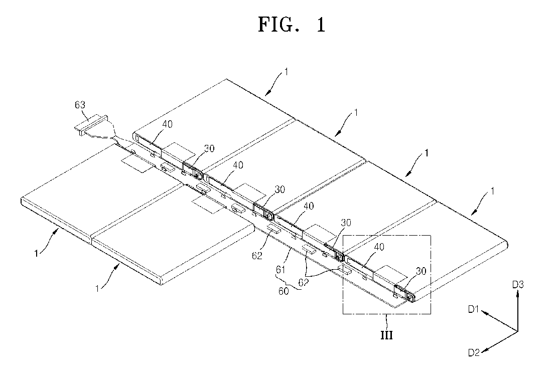
- FIG. 1 is a perspective view schematically illustrating a battery pack according to an embodiment of the present invention.
- FIG. 2 is an exploded perspective view of FIG. 1 .
- FIG. 3 is an enlarged perspective view illustrating a portion III of FIG. 1 .
- the battery pack includes a plurality of unit batteries 1 and a protection circuit module 60.
- Each of the unit batteries 1 includes first and second terminals 30 and 40, and is directly electrically connected to the protection circuit module 60.
- Each of the unit batteries 1 which is a rechargeable secondary battery may be a lithium-ion battery.
- Each of the unit batteries 1 is manufactured to have a prismatic shape, for example, a substantially hexahedral shape.
- Each of the unit batteries 1 includes a can 10 (see FIG. 4 ) and a cap plate 20 (see FIG. 4 ) sealing a side surface of the can 10.
- the unit batteries 1 may be arranged side by side in a first direction D1 such that the cap plates 20 are exposed in the same direction. For example, as shown in FIG.
- four unit batteries 1 may be arranged side by side in the first direction D1 such that the cap plates 20 are exposed in a second direction D2, and two unit batteries 1 may be arranged side by side in the first direction D1 such that the cap plates 20 are exposed in a direction -D2 that is opposite to the second direction D2.
- unit batteries 1 Although four unit batteries 1 are aligned and two unit batteries 1 are aligned to face each other in FIG. 1 , the number and arrangement of the unit batteries 1 are not limited thereto. Alternatively, two or more unit batteries 1 may be arranged side by side in the first direction D1.
- the first terminal 30 and the second terminal 40 are disposed on a side surface of each of the unit batteries 1, that is, on the cap plate 20. Any one of the first and second terminals 30 and 40 is a negative electrode of each of the unit batteries 1 and the other one is a positive electrode of each of the unit batteries 1. In FIG. 1 , the following explanation will be made on the assumption that the first terminal 30 is a negative electrode and the second terminal 40 is a positive electrode.
- the first terminal 30 is disposed on the cap plate 20, and a portion of the first terminal 30 disposed away from the cap plate 20 extends toward the protection circuit module 60. The portion of the first terminal 30 is bent.
- the second terminal 40 is disposed on the cap plate 20, and a portion of the second terminal 40 disposed away from the cpa plate 20 extends toward the protection circuit module 60. The portion of the second terminal 40 is bent.
- the bent end portions of the first and second terminals 30 and 40 are inserted into terminal holes 61 h formed in the protection circuit module 60, and each of the unit batteries 1 is electrically connected to the protection circuit module 60 when the bent end portions of the first and second terminals 30 and 40 are inserted into the terminal holes 61 h.
- the protection circuit module 60 may be disposed adjacent to the cap plates 20 of the unit batteries 1.
- the protection circuit module 60 may be electrically connected to the unit batteries 1 to control the unit batteries 1 to be charged/discharged, and may prevent overheating and explosion caused by overcharging, overdischarge, or overcurrent.
- the protection circuit module 60 includes a circuit board 61, and a plurality of protection devices 62 mounted on the circuit board 61.
- the circuit board 61 includes at least one terminal hole 61 h.
- the terminal hole 61 h may be formed in an edge of the circuit board 61, and each of the unit batteries 1 may be directly connected to the protection circuit module 60 when the first and second terminals 30 and 40 are inserted into the terminal holes 61 h.
- the end portions of the first and second terminals 30 and 40 may be inserted into the terminal holes 61 h formed in the circuit board 61, and the terminal holes 61 h may have slit shapes extending in the first direction D1.
- the end portion of the first terminal 30 and the end portion of the second terminal 40 are inserted into the terminal holes 61 h and are soldered.
- each of the unit batteries 1 is directly connected to the protection circuit module 60 through the first and second terminals 30 and 40 provided on the cap plate 20, the unit batteries 1 may be controlled by the protection circuit module 60 to be charged/discharged, and may be connected in parallel and/or series through wires formed on the protection circuit module 60. Since each of the unit batteries 1 is directly connected to the protection circuit module 60, an intermediate member for connecting the plurality of unit batteries 1 in parallel and/or series is not necessary. Accordingly, an additional space for the intermediate member is not necessary, and it is possible to reduce the total number of parts for manufacturing the battery pack.
- the circuit board 61 is disposed adjacent to the cap plate 20, and extends in the first direction D1.
- the circuit board 61 may be disposed on a plane adjacent to second surfaces 32 and 42 (see FIG. 4 ) of the first and second terminals 30 and 40, for example, on substantially the same plane as bottom surfaces of the unit batteries 1.
- a predetermined space may be formed between a top surface of the circuit board 61 and the cap plate 20, and the plurality of protection devices 62 may be disposed in the predetermined space.
- a height of each of the protection devices 62 may be equal to or less than a thickness of each of the unit batteries 1, that is, a distance between a first long side l1 (see FIG. 4 ) and a second long side l2, which is opposite to the first long side L1, of the cap plate 20 (see FIG. 4 ).
- the protection devices 62 may be effectively mounted without increasing a thickness and a width of the battery pack.
- the protection device 62 may be formed by selectively forming a safety element including a passive element such as a resistor or a condenser and an active element such as a field-effect transistor (FET), or integrated circuits.
- a connector 63 for supplying power to an external electronic device may be provided on a side of the protection circuit module 60.
- each of the unit batteries 1 including the first and second terminals 30 and 40 will be explained in detail with reference to FIG. 4 .
- FIG. 4 is an exploded perspective view illustrating one unit battery 1 according to an embodiment of the present invention.
- the unit battery 1 includes the can 10, an electrode assembly received in the can 10 through an opening formed in the can 10, the cap plate 20 sealing the opening of the can 10, and the first and second terminals 30 and 40.
- the can 10 having a substantially hexahedral shape with one side open may be formed of a metal material in order to increase strength.
- the can 10 may be formed of aluminum or an aluminum alloy.
- the opening may be sealed by the cap plate 20.
- the cap plate 20 may be formed of a metal material such as aluminum or an aluminum alloy, like the can 10. Contact portions between the cap plate 20 and the can 10 may be coupled by laser welding to maintain sealing engagement.
- Each of the can 10 and the cap plate 20 is formed of a metal material, and an outer circumferential surface of the can 10 is not surrounded by an insulating film such as a label. Accordingly, when the unit batteries 1 are arranged side by side as shown in FIG. 1 , since short-circuit may occur between adjacent unit batteries 1, facing surfaces of the adjacent unit batteries 1 may be insulated from each other to prevent the short-circuit. For example, both side surfaces of the can 10 which are exposed in the first direction D1 may be insulated by using an insulating tape I. Alternatively, the both side surfaces of the can 10 may be insulated by disposing an insulating barrier between adjacent unit batteries 1.
- the electrode assembly may include a first electrode plate and a second electrode plate each coated with an electrode active material, and a separator disposed between the first and second electrode plates.
- the electrode assembly may be manufactured by sequentially stacking the first electrode plate, the separator, and the second electrode plate and winding the first electrode plate, the separator, and the second electrode plate in a jelly roll shape.
- the electrode assembly has a jelly roll shape in FIG. 4
- the present embodiment is not limited thereto.
- the electrode assembly may have a stacked structure in which the first electrode plate, the separator, and the second electrode plate are sequentially stacked.
- An electrode pin 21 is formed on the cap plate 20.
- the first electrode plate is electrically connected to the electrode pin 21, and the second electrode plate is electrically connected to the cap plate 20. Since the first electrode plate and the second electrode plate have different polarities, the electrode pin 21 and the cap plate 20 have different polarities.
- the electrode pin 21 may have a polarity of a negative electrode
- the cap plate 20 may have a polarity of a positive electrode.
- a gasket 23 may be disposed between the electrode pin 21 and the cap plate 20 in order to prevent a short-circuit between the electrode pin 21 and the cap plate 20.
- the gasket 23 is formed of an insulating material, and prevents a short-circuit between the electrode pin 21 and the cap plate 20.
- the first terminal 30 and the second terminal 40 are disposed on the cap plate 20.
- the first terminal 30 is disposed on a portion (first area) of the cap plate 20, and the second terminal 40 is disposed on another portion (second area) of the cap plate 20.
- the first terminal 30 may be disposed on the cap plate 20 to be electrically connected to the electrode pin 21, and the second terminal 40 may be disposed on the cap plate 20 to be electrically connected to the cap plate 20.
- a connection piece 22 may be further provided on the cap plate 20 in order to improve weldability between the cap plate 20 and the second terminal 40 formed of different materials.
- the connection piece 22 is formed of the same material as that of the second terminal 40.
- each of the connection piece 22 and the first and second terminals 30 and 40 may be formed of nickel.
- the first terminal 30 may include a first surface 31 parallel to the cap plate 20, a second surface 32 bent from the first surface 31, and a third surface 33 bent from the second surface 32 and substantially parallel to the first surface 31.
- the first terminal l30 may include a temperature cutoff (TCO) 35.
- TCO temperature cutoff
- the first surface 31 of the first terminal 30 may be divided into a first portion 31 a and a second portion 31 b.
- the first portion 31 a and the second portion 31 b may be disposed on the same plane, and the TCO 35 may be electrically connected between the first portion 31 a and the second portion 31 b.
- one end 35a of the TCO 35 may be connected to an end of the first portion 31 a of the first surface 31, and the other end 35b of the TCO 35 may be connected to an end of the second portion 31 b of the first surface 31.
- the first terminal 30 Since the first terminal 30 is electrically connected to the electrode pin 21, the first terminal 30 has a polarity of a negative electrode. By contrast, since the cap plate 20 has a polarity of a positive electrode, a short-circuit may easily occur between the cap plate 20 and the first terminal 30 that is disposed on the cap plate 20. Accordingly, a holder 50 for electrically insulating the first terminal 30 and the cap plate 20 may be further provided between the first terminal 30 and the cap plate 20.
- the holder 50 is directly disposed on the cap plate 20, and includes a first opening OP1 through which the first surface 31 of the first terminal 30 is electrically connected to the electrode pin 21.
- the holder 50 may further include a second opening OP2 formed in a surface facing the TCO 35 in order for the TCO 35 included in the first terminal 30 to effectively respond to a temperature of the unit battery 1.
- the holder 50 may include a protrusion 51 for fixing the first terminal 30.
- the first portion 31 a of the first surface 31 of the first terminal 30 may be welded to the electrode pin 21 and the second portion 31 b of the first surface 31 of the first terminal 30 may be fixed to the protrusion 51.
- a hole 30h may be formed in the second portion 31 b of the first surface 31.
- the second surface 32 of the first terminal 30 may be bent in a direction substantially perpendicular to the first surface 31, and the third surface 33 may be bent in a direction substantially perpendicular to the second surface 32.
- the second surface 32 is disposed adjacent to the first long side l1 of the cap plate 20.
- the third surface 33 of the first terminal 30 is inserted as an end portion of the first terminal 30 into the terminal hole 61 h of the protection circuit module 60 as described above with reference to FIGS. 1 through 3 .
- the second terminal 40 may include a first surface 41 parallel to the cap plate 20, a second surface 42 bent from the first surface 41, and a third surface 43 bent from the second surface 42 and substantially parallel to the first surface 41.
- the second surface 42 of the second terminal 40 may be bent in a direction substantially perpendicular to the first surface 41, and the third surface 43 may be bent in a direction substantially perpendicular to the second surface 42.
- the third surface 43 of the second terminal 40 is inserted as an end portion of the second terminal 40 into the terminal hole 61 h of the protection circuit module 60 as described above with reference to FIGS. 1 through 3 .
- each of unit batteries since each of unit batteries is directly connected to a protection circuit module through first and second terminals, the unit batteries may be controlled by the protection circuit module to be charged/discharged and may be connected in parallel and/or series through wires formed on the protection circuit module. Accordingly, an intermediate member for connecting the plurality of unit batteries in parallel and/or series is not necessary, an additional space for the intermediate member is not necessary, and it is possible to reduce the total number of parts for manufacturing a battery pack.
Landscapes
- Chemical & Material Sciences (AREA)
- Chemical Kinetics & Catalysis (AREA)
- Electrochemistry (AREA)
- General Chemical & Material Sciences (AREA)
- Engineering & Computer Science (AREA)
- Microelectronics & Electronic Packaging (AREA)
- Manufacturing & Machinery (AREA)
- Battery Mounting, Suspending (AREA)
- Connection Of Batteries Or Terminals (AREA)
Abstract
a plurality of prismatic unit batteries (1) that each comprise a can (10) having an opening, an electrode assembly received in the can (10) and a cap plate (20) sealing the opening of the can (10), and are arranged side by side in a first direction such that the cap plates (20) are exposed in the same direction; and
a protection circuit module (60) that is disposed adjacent to the cap plates (20) of the plurality of unit batteries (1), and comprises a circuit board (61) extending in the first direction,
wherein each of the plurality of unit batteries (1) comprises:
a first terminal (30) that is disposed on a first area of the cap plate (20) and connects the unit battery (1) and the protection circuit module (60); and
a second terminal (40) that is disposed on a second area of the cap plate (20) and connects the unit battery (1) and the protection circuit module (60);
characterized in that,
the protection circuit module (60) is arranged such that a wide surface of the protection circuit module (60) is located perpendicular to a wide surface of the cap plate (20); and
the circuit board (61) comprises at least one terminal hole (61 h), wherein an end portion of at least one of the first terminal (30) and the second terminal (40) of the unit battery (1) is inserted into the terminal hole (61 h).
Description
- The present invention relates to a battery pack.
- With the development of wireless Internet or communication technology, portable computers which may be operated by using a battery without a power supply device have rapidly spread. In general, portable computers are widely used for work or personal purposes because of their compact designs, easy portability, and high mobility. A portable computer may include an internal battery pack in order to be used in various places without being affected by a power supply device. Also, the internal battery pack may include unit batteries that may be repeatedly re-charged/discharged.
- The present invention relates to a structure of a battery pack.
- According to a first aspect the present invention provides a battery pack comprising: a plurality of prismatic unit batteries that each comprise a can having an opening, an electrode assembly received in the can and a cap plate sealing the opening of the can, and are arranged side by side in a first direction such that the cap plates are exposed in the same direction; and a protection circuit module that is disposed adjacent to the cap plates of the plurality of unit batteries, and comprises a circuit board extending in the first direction; wherein each of the plurality of unit batteries comprises: a first terminal that is disposed on a first area of the cap plate and connects the unit battery and the protection circuit module; and a second terminal that is disposed on a second area of the cap plate and connects the unit battery and the protection circuit module; characterized in that, the protection circuit module is arranged such that a wide surface of the protection circuit module is located perpendicular to a wide surface of the cap plate; and the circuit board comprises at least one terminal hole, wherein an end portion of at least one of the first terminal and the second terminal of the unit battery is inserted into the terminal hole.
- The circuit board of the battery pack of the invention may comprise a plurality of terminal holes, wherein an end portion of the first terminal and the second terminal of each of the plurality of unit batteries is inserted into one of the terminal holes, respectively.
- On the circuit board of the protection circuit module of the battery pack of the invention wires can be formed such as to electrically connect the plurality of unit batteries in parallel and/or in series.
- The end portions of the terminals of the plurality of unit batteries may be formed such that hook-like structures are achieved. The battery pack of the invention may comprise terminals, wherein at least one of the first terminal and the second terminal comprises: a first surface that is parallel to the cap plate; a second surface that is bent in a direction substantially perpendicular to the first surface; and a third surface that is bent in a direction substantially perpendicular to the second surface and is parallel to the first surface. Preferably, the second surface is disposed adjacent to a first long side of the cap plate, and the circuit board is disposed on a plane adjacent to the second surface. The third surface is preferably inserted into the terminal hole to be electrically connected to the circuit board.
- It is to be understood that for the purpose of the present invention the term "surface" can be used interchangingly with the terms "member" and/or "body" in order to define the structure of the terminals, in particular in order to define first, second and third surfaces of the first and/or second terminal of the unit batteries.
- The protection circuit module of the battery pack of the invention may further comprise a protection device and a height of the protection device may be equal to or less than a distance between a first long side of the cap plate and a second long side of the cap plate that is opposite to the first long side.
- In the battery pack of the invention, facing surfaces of adjacent unit batteries from among the plurality of unit batteries can be insulated from each other.
- Preferably, each of the unit batteries of the battery pack of the invention comprises an electrode pin that is formed on the cap plate and has a first polarity, wherein the cap plate has a second polarity that is different from the first polarity. The first terminal may be formed to electrically connect the electrode pin and the protection circuit module, wherein the second terminal may electrically connect the cap plate and the protection circuit module.
- The battery pack of the invention may further comprise a holder that is disposed between the first terminal and the cap plate, and insulates the cap plate and the first terminal while exposing the electrode pin.
- In the battery pack of the invention, the first terminal may further comprise a temperature cutoff.
- In the battery pack of the invention, the unit battery may further comprise a connection piece that is formed on the cap plate to be directly connected to the second terminal, and is formed of the same material as a material of the second terminal.
- According to another aspect of the present invention, there is provided a battery pack including: a plurality of unit batteries that each include a can having an opening, an electrode assembly received in the can and including a first electrode plate, a second electrode plate, and a separator disposed between the first electrode plate and the second electrode plate, and a cap plate sealing the opening of the can, and are arranged side by side in a first direction such that the cap plates are exposed in the same direction; and a protection circuit module that is disposed adjacent to the cap plates of the plurality of unit batteries, and includes a circuit board extending in the first direction and a protection device mounted on the circuit board, wherein each of the plurality of unit batteries includes: a first terminal that is disposed on a first area of the cap plate and connects the unit battery and the protection circuit module; and a second terminal that is disposed on a second area of the cap plate and connects the unit battery and the protection circuit module.
- The circuit board may include at least one terminal hole, wherein an end portion of at least one of the first terminal and the second terminal is inserted into the terminal hole.
- At least one of the first terminal and the second terminal may include: a first surface that is parallel to the cap plate; a second surface that is bent in a direction substantially perpendicular to the first surface; and a third surface that is bent in a direction substantially perpendicular to the second surface and is parallel to the first surface.
- The second surface may be disposed adjacent to a first long side of the cap plate, and the circuit board is disposed on a plane adjacent to the second surface.
- A height of the protection device may be equal to or less than a distance between the first long side of the cap plate and a second long side of the cap plate that is opposite to the first long side.
- The circuit board may include at least one terminal hole, wherein the third surface is inserted into the terminal hole to be electrically connected to the circuit board.
- Each of the unit batteries may include an electrode pin that is formed on the cap plate and has a first polarity, wherein the cap plate has a second polarity that is different from the first polarity.
- The first terminal may electrically connect the electrode pin and the protection circuit module, and the second terminal may electrically connect the cap plate and the protection circuit module.
- The battery pack may further include a holder that is disposed between the first terminal and the cap plate, and insulates the cap plate and the first terminal while exposing the electrode pin.
- The first terminal may further include a temperature cutoff (TCO).
- Facing surfaces of adjacent unit batteries from among the plurality of unit batteries may be insulated from each other.
- According to a further aspect of the present invention, there is provided a battery pack including: a plurality of unit batteries that each include a can including an opening and formed of a metal material, an electrode assembly received in the can and including a first electrode plate, a second electrode plate, and a separator disposed between the first electrode plate and the second electrode plate, and a cap plate sealing the opening of the cap; and a protection circuit module that is disposed adjacent to the cap plates of the plurality of unit batteries and includes a circuit board and a protection device, wherein each of the plurality of unit batteries includes: a first terminal that electrically connects the protection circuit module and an electrode pin that is formed on the cap plate and has a first polarity; and a second terminal that electrically connects the protective circuit module and the cap plate having a polarity that is opposite to the first polarity.
- The circuit board may include at least one terminal hole.
- An end portion of the first terminal and an end portion of the second terminal may be inserted into the terminal hole.
- The battery pack may further include a holder that is disposed between the first terminal and the cap plate, and insulates the cap plate and the first terminal while exposing the electrode pin.
- The first terminal may include: a first surface that is connected to the electrode pin; a second surface that is bent from the first surface; and a third surface that is bent from the second surface and is parallel to the first surface.
- The first surface may be divided into a first portion and a second portion, wherein the first portion and the second portion are electrically connected to each other through a temperature cutoff (TCO) that is disposed between the first portion and the second portion.
- The second terminal may include: a first surface that is connected to a portion of the cap plate; a second surface that is bent from the first surface; and a third surface that is bent from the second surface and is parallel to the first surface.
- The battery pack may further include a connection piece that is formed on the cap plate to be directly connected to the second terminal, and is formed of the same material as a material of the second terminal.
- Facing surfaces of adjacent unit batteries from among the plurality of unit batteries may be insulated from each other.
-
-
FIG. 1 is a perspective view schematically illustrating a battery pack according to an embodiment of the present invention. -
FIG. 2 is an exploded perspective view ofFIG. 1 . -
FIG. 3 is an enlarged perspective view illustrating a portion III ofFIG. 1 . -
FIG. 4 is an exploded perspective view illustrating a unit battery according to an embodiment of the present invention. - The present invention will now be described more fully with reference to the accompanying drawings, in which exemplary embodiments of the present invention are shown. It should be understood, however, that there is no intent to limit exemplary embodiments of the present invention to the particular forms disclosed, but conversely, exemplary embodiments of the present invention are to cover all modifications, equivalents, and alternatives falling within the spirit and scope of the present invention. In the following description of the present invention, a detailed description of known functions and configurations incorporated herein will be omitted when it may make the subject matter of the present invention unclear. It will be understood that, although the terms first, second, etc. may be used herein to describe various elements, these elements should not be limited by these terms. These terms are only used to distinguish one element from another. The terminology used herein is for the purpose of describing particular embodiments only and is not intended to be limiting of exemplary embodiments of the invention. As used herein, the singular forms "a", "an" and "the" are intended to include the plural forms as well, unless the context clearly indicates otherwise. It will be further understood that the terms "comprises", "comprising,", "includes" and/or "including", when used herein, specify the presence of stated features, integers, steps, operations, elements, parts, or combinations thereof, but do not preclude the presence or addition of one or more other features, integers, steps, operations, elements, parts, or combinations thereof. A function mark "/" may used to mean "and" or "or" according to the context.
- Like numerals denote like elements throughout. It will also be understood that when a layer, film, region, or plate is referred to as being "on" another layer, film, region, or plate, it can be directly on the other layer, film, region, or plate, or intervening layers, films, regions, or plates may also be present therebetween.
-
FIG. 1 is a perspective view schematically illustrating a battery pack according to an embodiment of the present invention.FIG. 2 is an exploded perspective view ofFIG. 1 .FIG. 3 is an enlarged perspective view illustrating a portion III ofFIG. 1 . - Referring to
FIGS. 1 and2 , the battery pack includes a plurality ofunit batteries 1 and aprotection circuit module 60. Each of theunit batteries 1 includes first andsecond terminals protection circuit module 60. - Each of the
unit batteries 1 which is a rechargeable secondary battery may be a lithium-ion battery. Each of theunit batteries 1 is manufactured to have a prismatic shape, for example, a substantially hexahedral shape. Each of theunit batteries 1 includes a can 10 (seeFIG. 4 ) and a cap plate 20 (seeFIG. 4 ) sealing a side surface of thecan 10. Theunit batteries 1 may be arranged side by side in a first direction D1 such that thecap plates 20 are exposed in the same direction. For example, as shown inFIG. 1 , fourunit batteries 1 may be arranged side by side in the first direction D1 such that thecap plates 20 are exposed in a second direction D2, and twounit batteries 1 may be arranged side by side in the first direction D1 such that thecap plates 20 are exposed in a direction -D2 that is opposite to the second direction D2. - Although four
unit batteries 1 are aligned and twounit batteries 1 are aligned to face each other inFIG. 1 , the number and arrangement of theunit batteries 1 are not limited thereto. Alternatively, two ormore unit batteries 1 may be arranged side by side in the first direction D1. - The
first terminal 30 and thesecond terminal 40 are disposed on a side surface of each of theunit batteries 1, that is, on thecap plate 20. Any one of the first andsecond terminals unit batteries 1 and the other one is a positive electrode of each of theunit batteries 1. InFIG. 1 , the following explanation will be made on the assumption that thefirst terminal 30 is a negative electrode and thesecond terminal 40 is a positive electrode. - The
first terminal 30 is disposed on thecap plate 20, and a portion of thefirst terminal 30 disposed away from thecap plate 20 extends toward theprotection circuit module 60. The portion of thefirst terminal 30 is bent. - The
second terminal 40 is disposed on thecap plate 20, and a portion of thesecond terminal 40 disposed away from thecpa plate 20 extends toward theprotection circuit module 60. The portion of thesecond terminal 40 is bent. - The bent end portions of the first and
second terminals terminal holes 61 h formed in theprotection circuit module 60, and each of theunit batteries 1 is electrically connected to theprotection circuit module 60 when the bent end portions of the first andsecond terminals - The
protection circuit module 60 may be disposed adjacent to thecap plates 20 of theunit batteries 1. Theprotection circuit module 60 may be electrically connected to theunit batteries 1 to control theunit batteries 1 to be charged/discharged, and may prevent overheating and explosion caused by overcharging, overdischarge, or overcurrent. Theprotection circuit module 60 includes acircuit board 61, and a plurality ofprotection devices 62 mounted on thecircuit board 61. - The
circuit board 61 includes at least oneterminal hole 61 h. Theterminal hole 61 h may be formed in an edge of thecircuit board 61, and each of theunit batteries 1 may be directly connected to theprotection circuit module 60 when the first andsecond terminals - As shown in
FIG. 3 , the end portions of the first andsecond terminals circuit board 61, and the terminal holes 61 h may have slit shapes extending in the first direction D1. The end portion of thefirst terminal 30 and the end portion of thesecond terminal 40 are inserted into the terminal holes 61 h and are soldered. - Since each of the
unit batteries 1 is directly connected to theprotection circuit module 60 through the first andsecond terminals cap plate 20, theunit batteries 1 may be controlled by theprotection circuit module 60 to be charged/discharged, and may be connected in parallel and/or series through wires formed on theprotection circuit module 60. Since each of theunit batteries 1 is directly connected to theprotection circuit module 60, an intermediate member for connecting the plurality ofunit batteries 1 in parallel and/or series is not necessary. Accordingly, an additional space for the intermediate member is not necessary, and it is possible to reduce the total number of parts for manufacturing the battery pack. - The
circuit board 61 is disposed adjacent to thecap plate 20, and extends in the first direction D1. In this case, thecircuit board 61 may be disposed on a plane adjacent tosecond surfaces 32 and 42 (seeFIG. 4 ) of the first andsecond terminals unit batteries 1. As thecircuit board 61 is disposed in this manner, a predetermined space may be formed between a top surface of thecircuit board 61 and thecap plate 20, and the plurality ofprotection devices 62 may be disposed in the predetermined space. A height of each of theprotection devices 62 may be equal to or less than a thickness of each of theunit batteries 1, that is, a distance between a first long side l1 (seeFIG. 4 ) and a second long side l2, which is opposite to the first long side L1, of the cap plate 20 (seeFIG. 4 ). In this structure, theprotection devices 62 may be effectively mounted without increasing a thickness and a width of the battery pack. - The
protection device 62 may be formed by selectively forming a safety element including a passive element such as a resistor or a condenser and an active element such as a field-effect transistor (FET), or integrated circuits. Aconnector 63 for supplying power to an external electronic device may be provided on a side of theprotection circuit module 60. - A structure of each of the
unit batteries 1 including the first andsecond terminals FIG. 4 . -
FIG. 4 is an exploded perspective view illustrating oneunit battery 1 according to an embodiment of the present invention. - Referring to
FIG. 4 , theunit battery 1 includes thecan 10, an electrode assembly received in thecan 10 through an opening formed in thecan 10, thecap plate 20 sealing the opening of thecan 10, and the first andsecond terminals - The
can 10 having a substantially hexahedral shape with one side open may be formed of a metal material in order to increase strength. For example, thecan 10 may be formed of aluminum or an aluminum alloy. After the electrode assembly is inserted into thecan 10, the opening may be sealed by thecap plate 20. Thecap plate 20 may be formed of a metal material such as aluminum or an aluminum alloy, like thecan 10. Contact portions between thecap plate 20 and thecan 10 may be coupled by laser welding to maintain sealing engagement. - Each of the
can 10 and thecap plate 20 is formed of a metal material, and an outer circumferential surface of thecan 10 is not surrounded by an insulating film such as a label. Accordingly, when theunit batteries 1 are arranged side by side as shown inFIG. 1 , since short-circuit may occur betweenadjacent unit batteries 1, facing surfaces of theadjacent unit batteries 1 may be insulated from each other to prevent the short-circuit. For example, both side surfaces of thecan 10 which are exposed in the first direction D1 may be insulated by using an insulating tape I. Alternatively, the both side surfaces of thecan 10 may be insulated by disposing an insulating barrier betweenadjacent unit batteries 1. - The electrode assembly (not shown) may include a first electrode plate and a second electrode plate each coated with an electrode active material, and a separator disposed between the first and second electrode plates. The electrode assembly may be manufactured by sequentially stacking the first electrode plate, the separator, and the second electrode plate and winding the first electrode plate, the separator, and the second electrode plate in a jelly roll shape.
- Although the electrode assembly has a jelly roll shape in
FIG. 4 , the present embodiment is not limited thereto. Alternatively, the electrode assembly may have a stacked structure in which the first electrode plate, the separator, and the second electrode plate are sequentially stacked. - An
electrode pin 21 is formed on thecap plate 20. The first electrode plate is electrically connected to theelectrode pin 21, and the second electrode plate is electrically connected to thecap plate 20. Since the first electrode plate and the second electrode plate have different polarities, theelectrode pin 21 and thecap plate 20 have different polarities. For example, theelectrode pin 21 may have a polarity of a negative electrode, and thecap plate 20 may have a polarity of a positive electrode. In this case, agasket 23 may be disposed between theelectrode pin 21 and thecap plate 20 in order to prevent a short-circuit between theelectrode pin 21 and thecap plate 20. Thegasket 23 is formed of an insulating material, and prevents a short-circuit between theelectrode pin 21 and thecap plate 20. - The
first terminal 30 and thesecond terminal 40 are disposed on thecap plate 20. Thefirst terminal 30 is disposed on a portion (first area) of thecap plate 20, and thesecond terminal 40 is disposed on another portion (second area) of thecap plate 20. In detail, thefirst terminal 30 may be disposed on thecap plate 20 to be electrically connected to theelectrode pin 21, and thesecond terminal 40 may be disposed on thecap plate 20 to be electrically connected to thecap plate 20. In this case, aconnection piece 22 may be further provided on thecap plate 20 in order to improve weldability between thecap plate 20 and thesecond terminal 40 formed of different materials. Theconnection piece 22 is formed of the same material as that of thesecond terminal 40. For example, each of theconnection piece 22 and the first andsecond terminals - The
first terminal 30 may include afirst surface 31 parallel to thecap plate 20, asecond surface 32 bent from thefirst surface 31, and athird surface 33 bent from thesecond surface 32 and substantially parallel to thefirst surface 31. - The first terminal l30 may include a temperature cutoff (TCO) 35. To this end, the
first surface 31 of thefirst terminal 30 may be divided into afirst portion 31 a and a second portion 31 b. Thefirst portion 31 a and the second portion 31 b may be disposed on the same plane, and theTCO 35 may be electrically connected between thefirst portion 31 a and the second portion 31 b. For example, oneend 35a of theTCO 35 may be connected to an end of thefirst portion 31 a of thefirst surface 31, and theother end 35b of theTCO 35 may be connected to an end of the second portion 31 b of thefirst surface 31. - Since the
first terminal 30 is electrically connected to theelectrode pin 21, thefirst terminal 30 has a polarity of a negative electrode. By contrast, since thecap plate 20 has a polarity of a positive electrode, a short-circuit may easily occur between thecap plate 20 and thefirst terminal 30 that is disposed on thecap plate 20. Accordingly, aholder 50 for electrically insulating thefirst terminal 30 and thecap plate 20 may be further provided between thefirst terminal 30 and thecap plate 20. - The
holder 50 is directly disposed on thecap plate 20, and includes a first opening OP1 through which thefirst surface 31 of thefirst terminal 30 is electrically connected to theelectrode pin 21. Theholder 50 may further include a second opening OP2 formed in a surface facing theTCO 35 in order for theTCO 35 included in thefirst terminal 30 to effectively respond to a temperature of theunit battery 1. - The
holder 50 may include aprotrusion 51 for fixing thefirst terminal 30. In a state where thefirst terminal 30 is mounted on theholder 50, thefirst portion 31 a of thefirst surface 31 of thefirst terminal 30 may be welded to theelectrode pin 21 and the second portion 31 b of thefirst surface 31 of thefirst terminal 30 may be fixed to theprotrusion 51. Ahole 30h may be formed in the second portion 31 b of thefirst surface 31. When theprotrusion 51 is inserted into thehole 30h and then heat is applied to a portion of an upper end of theprotrusion 51, the portion of the upper end of theprotrusion 51 may melt and thefirst terminal 30 may be fixed to theholder 50. Atape 55 fixed to theholder 50 may be further attached in order to prevent thefirst terminal 30 that is fixed to theholder 50 and welded to theelectrode pin 21 from being separated from theunit battery 1. - The
second surface 32 of thefirst terminal 30 may be bent in a direction substantially perpendicular to thefirst surface 31, and thethird surface 33 may be bent in a direction substantially perpendicular to thesecond surface 32. Thesecond surface 32 is disposed adjacent to the first long side l1 of thecap plate 20. Thethird surface 33 of thefirst terminal 30 is inserted as an end portion of thefirst terminal 30 into theterminal hole 61 h of theprotection circuit module 60 as described above with reference toFIGS. 1 through 3 . - The
second terminal 40 may include afirst surface 41 parallel to thecap plate 20, asecond surface 42 bent from thefirst surface 41, and athird surface 43 bent from thesecond surface 42 and substantially parallel to thefirst surface 41. Thesecond surface 42 of thesecond terminal 40 may be bent in a direction substantially perpendicular to thefirst surface 41, and thethird surface 43 may be bent in a direction substantially perpendicular to thesecond surface 42. Thethird surface 43 of thesecond terminal 40 is inserted as an end portion of thesecond terminal 40 into theterminal hole 61 h of theprotection circuit module 60 as described above with reference toFIGS. 1 through 3 . - It is to be understood that for the purpose of the present invention the term "surface" can be used interchangingly with the terms "member" and/or "body" in order to define the structure of the terminals, in particular in order to define first, second and third surfaces of the first and/or second terminal of the unit batteries.
- According to the one or more embodiments of the present invention, since each of unit batteries is directly connected to a protection circuit module through first and second terminals, the unit batteries may be controlled by the protection circuit module to be charged/discharged and may be connected in parallel and/or series through wires formed on the protection circuit module. Accordingly, an intermediate member for connecting the plurality of unit batteries in parallel and/or series is not necessary, an additional space for the intermediate member is not necessary, and it is possible to reduce the total number of parts for manufacturing a battery pack.
- While the present invention has been particularly shown and described with reference to exemplary embodiments thereof, they are provided for the purposes of illustration and it will be understood by those of ordinary skill in the art that various modifications and equivalent other embodiments may be made from the present invention.
Claims (13)
- A battery pack comprising:a plurality of prismatic unit batteries (1) that each comprise a can (10) having an opening, an electrode assembly received in the can (10) and a cap plate (20) sealing the opening of the can (10), and are arranged side by side in a first direction such that the cap plates (20) are exposed in the same direction; anda protection circuit module (60) that is disposed adjacent to the cap plates (20) of the plurality of unit batteries (1), and comprises a circuit board (61) extending in the first direction,wherein each of the plurality of unit batteries (1) comprises:a first terminal (30) that is disposed on a first area of the cap plate (20) and connects the unit battery (1) and the protection circuit module (60); anda second terminal (40) that is disposed on a second area of the cap plate (20) and connects the unit battery (1) and the protection circuit module (60);characterized in that,wherein an end portion of at least one of the first terminal (30) and the second terminal (40) of the unit battery (1) is inserted into the terminal hole (61 h).
the protection circuit module (60) is arranged such that a wide surface of the protection circuit module (60) is located perpendicular to a wide surface of the cap plate (20); and
the circuit board (61) comprises at least one terminal hole (61 h), - The battery pack of claim 1, wherein the circuit board (61) comprises a plurality of terminal holes (61 h),
wherein an end portion of the first terminal (30) and the second terminal (40) of each of the plurality of unit batteries (1) is inserted into one of the terminal holes (61 h) respectively. - The battery pack of claim 1 or 2, wherein wires are formed on the circuit board (61) of the protection circuit module (60) such as to electrically connect the plurality of unit batteries (1) in parallel and/or in series.
- The battery pack of one of the preceding claims, wherein at least one of the first terminal (30) and the second terminal (40) comprises:a first member (31, 41) that is parallel to the cap plate (20);a second member (32, 42) that is bent in a direction substantially perpendicular to the first surface (31, 41); anda third member (33, 43) that is bent in a direction substantially perpendicular to the second surface (32, 42) and is parallel to the first surface (31, 41).
- The battery pack of claim 4, wherein the second member (32, 42) is disposed adjacent to a first long side (l1) of the cap plate (20), and the circuit board (61) is disposed on a plane adjacent to the second member (32, 42).
- The battery pack of one of the preceding claims, wherein the protection circuit module (60) further comprises a protection device (62) and wherein a height of the protection device (62) is equal to or less than a distance between a first long side (11) of the cap plate (20) and a second long side (l2) of the cap plate (20) that is opposite to the first long side (l1).
- The battery pack of one of claims 4 to 6, wherein the third member (33, 43) is inserted into the terminal hole (61 h) to be electrically connected to the circuit board (61).
- The battery pack of one of the preceding claims, wherein facing surfaces of adjacent unit batteries (1) from among the plurality of unit batteries (1) are insulated from each other.
- The battery pack of one of the preceding claims, wherein each of the unit batteries (1) comprises an electrode pin (21) that is formed on the cap plate (20) and has a first polarity,
wherein the cap plate (20) has a second polarity that is different from the first polarity. - The battery pack of claim 9, wherein the first terminal (30) electrically connects the electrode pin (21) and the protection circuit module (60), and the second terminal (40) electrically connects the cap plate (20) and the protection circuit module (60).
- The battery pack of claim 9 or 10, further comprising a holder (50) that is disposed between the first terminal (30) and the cap plate (20), and insulates the cap plate (20) and the first terminal (30) while exposing the electrode pin (21).
- The battery pack of one of claims 9 to 11, wherein the first terminal (30) further comprises a temperature cutoff (35).
- The battery pack of one of claims 9 to 12, further comprising a connection piece (22) that is formed on the cap plate (20) to be directly connected to the second terminal (40), and is formed of the same material as a material of the second terminal (40).
Applications Claiming Priority (1)
| Application Number | Priority Date | Filing Date | Title |
|---|---|---|---|
| US201361844370P | 2013-07-09 | 2013-07-09 |
Publications (3)
| Publication Number | Publication Date |
|---|---|
| EP2824730A2 true EP2824730A2 (en) | 2015-01-14 |
| EP2824730A3 EP2824730A3 (en) | 2015-04-08 |
| EP2824730B1 EP2824730B1 (en) | 2017-05-17 |
Family
ID=49667075
Family Applications (1)
| Application Number | Title | Priority Date | Filing Date |
|---|---|---|---|
| EP13194977.8A Active EP2824730B1 (en) | 2013-07-09 | 2013-11-29 | Battery Pack |
Country Status (3)
| Country | Link |
|---|---|
| US (2) | US9385362B2 (en) |
| EP (1) | EP2824730B1 (en) |
| KR (1) | KR101483131B1 (en) |
Families Citing this family (9)
| Publication number | Priority date | Publication date | Assignee | Title |
|---|---|---|---|---|
| KR20170031405A (en) * | 2015-09-11 | 2017-03-21 | 주식회사 만도 | Electric brake system |
| USD843934S1 (en) * | 2017-08-04 | 2019-03-26 | Apple Inc. | Battery for an electronic device |
| KR102591513B1 (en) * | 2018-04-16 | 2023-10-19 | 삼성에스디아이 주식회사 | Battery Pack |
| CN109004167B (en) * | 2018-06-15 | 2023-12-01 | 宁德时代新能源科技股份有限公司 | battery module |
| USD906234S1 (en) | 2018-08-23 | 2020-12-29 | Apple Inc. | Battery for an electronic device |
| USD938905S1 (en) | 2019-05-15 | 2021-12-21 | Apple Inc. | Battery for an electronic device |
| US11509159B2 (en) | 2019-08-28 | 2022-11-22 | Microsoft Technology Licensing, Llc | System and method for thermal cutoff protection device control from an external component |
| USD929319S1 (en) | 2019-11-22 | 2021-08-31 | Apple Inc. | Battery for an electronic device |
| CN119315187B (en) * | 2024-10-16 | 2026-04-24 | 东莞新能德科技有限公司 | Battery module and electric equipment |
Family Cites Families (21)
| Publication number | Priority date | Publication date | Assignee | Title |
|---|---|---|---|---|
| EP1271672A4 (en) | 2000-03-14 | 2007-09-05 | Matsushita Electric Industrial Co Ltd | SECONDARY CELL AND METHOD FOR FIXING LADDER AND BATTERY POWER SUPPLY UNIT |
| JP3507428B2 (en) * | 2000-11-02 | 2004-03-15 | 松下電器産業株式会社 | Battery lead joining method |
| JP3882818B2 (en) * | 2004-01-15 | 2007-02-21 | ソニー株式会社 | Battery pack |
| KR20040062914A (en) * | 2004-06-11 | 2004-07-09 | 주식회사 다모텍 | Manufacture Process of lithium ion polymer cell Battery pack that hook type |
| US8586221B2 (en) | 2007-01-17 | 2013-11-19 | Samsung Sdi Co., Ltd. | Rechargeable battery with protective circuit board lead plates connection |
| KR101011802B1 (en) * | 2007-12-14 | 2011-02-07 | 주식회사 엘지화학 | Secondary Battery Packs and PCCs with Excellent Manufacturing Process |
| JP5340676B2 (en) | 2008-08-29 | 2013-11-13 | 三洋電機株式会社 | Battery system |
| KR20100060677A (en) | 2008-11-28 | 2010-06-07 | 삼성에스디아이 주식회사 | Battery pack |
| US8557411B2 (en) | 2009-08-14 | 2013-10-15 | Samsung Sdi Co., Ltd. | Secondary battery with a connection tab folded around an insulator and method of manufacturing the same |
| KR101230495B1 (en) | 2010-02-01 | 2013-02-06 | 주식회사 엘지화학 | Battery Pack of High Capacity |
| KR101250197B1 (en) | 2010-05-28 | 2013-04-03 | 주식회사 엘지화학 | Battery Pack of Novel Structure |
| KR101289282B1 (en) * | 2010-05-28 | 2013-07-24 | 주식회사 엘지화학 | Battery Pack of Compact Structure |
| US20110300414A1 (en) * | 2010-06-07 | 2011-12-08 | Woonseong Baek | Cap assembly and rechargeable battery having the same |
| US9451710B2 (en) * | 2010-08-26 | 2016-09-20 | Samsung Sdi Co., Ltd. | Battery pack |
| KR101210093B1 (en) | 2010-12-01 | 2012-12-07 | 삼성에스디아이 주식회사 | Connecting tab and secondary battery having the same |
| KR101261707B1 (en) * | 2011-02-11 | 2013-05-06 | 삼성에스디아이 주식회사 | Battery pack including gas discharging portion |
| KR101234241B1 (en) | 2011-02-17 | 2013-02-18 | 삼성에스디아이 주식회사 | Rechargeable Battery pack |
| US9065085B2 (en) | 2011-04-19 | 2015-06-23 | Samsung Sdi Co., Ltd. | Battery pack |
| DE102011079289A1 (en) | 2011-07-18 | 2013-01-24 | Sb Limotive Company Ltd. | A method of manufacturing a battery having a metallic housing and an electrical insulating layer covering the outside of the housing, and a battery manufactured by the method |
| US9203061B2 (en) * | 2011-10-07 | 2015-12-01 | Samsung Sdi Co., Ltd. | Rechargeable battery |
| KR101397027B1 (en) | 2012-09-11 | 2014-06-27 | 삼성에스디아이 주식회사 | Battery pack |
-
2013
- 2013-10-30 KR KR1020130130323A patent/KR101483131B1/en active Active
- 2013-11-11 US US14/077,179 patent/US9385362B2/en active Active
- 2013-11-29 EP EP13194977.8A patent/EP2824730B1/en active Active
-
2014
- 2014-07-10 US US14/328,666 patent/US9825276B2/en active Active
Non-Patent Citations (1)
| Title |
|---|
| None |
Also Published As
| Publication number | Publication date |
|---|---|
| US9385362B2 (en) | 2016-07-05 |
| US20150017484A1 (en) | 2015-01-15 |
| US9825276B2 (en) | 2017-11-21 |
| EP2824730A3 (en) | 2015-04-08 |
| EP2824730B1 (en) | 2017-05-17 |
| US20150017514A1 (en) | 2015-01-15 |
| KR101483131B1 (en) | 2015-01-15 |
Similar Documents
| Publication | Publication Date | Title |
|---|---|---|
| EP2824730B1 (en) | Battery Pack | |
| EP2073295B1 (en) | Protective circuit board for a battery | |
| JP6153182B2 (en) | Circuit board for secondary battery and battery pack including the same | |
| EP2905824B1 (en) | Battery pack | |
| KR101483133B1 (en) | Rechargeable battery | |
| KR101502901B1 (en) | Battery pack | |
| KR101493829B1 (en) | Battery Pack | |
| EP3016171B1 (en) | Secondary battery and secondary battery pack including the same | |
| KR102619723B1 (en) | Battery pack | |
| KR102401752B1 (en) | Secondary battery | |
| KR101430619B1 (en) | Battery Pack | |
| CN104282870B (en) | Battery | |
| EP3021382A1 (en) | Secondary battery | |
| CN105990601B (en) | Battery | |
| KR101502899B1 (en) | Battery Pack | |
| US20150228960A1 (en) | Battery pack | |
| KR101648891B1 (en) | Battery Pack | |
| KR20150094487A (en) | Battery Pack | |
| KR20170036331A (en) | Battery pack |
Legal Events
| Date | Code | Title | Description |
|---|---|---|---|
| 17P | Request for examination filed |
Effective date: 20131129 |
|
| AK | Designated contracting states |
Kind code of ref document: A2 Designated state(s): AL AT BE BG CH CY CZ DE DK EE ES FI FR GB GR HR HU IE IS IT LI LT LU LV MC MK MT NL NO PL PT RO RS SE SI SK SM TR |
|
| AX | Request for extension of the european patent |
Extension state: BA ME |
|
| PUAI | Public reference made under article 153(3) epc to a published international application that has entered the european phase |
Free format text: ORIGINAL CODE: 0009012 |
|
| PUAL | Search report despatched |
Free format text: ORIGINAL CODE: 0009013 |
|
| AK | Designated contracting states |
Kind code of ref document: A3 Designated state(s): AL AT BE BG CH CY CZ DE DK EE ES FI FR GB GR HR HU IE IS IT LI LT LU LV MC MK MT NL NO PL PT RO RS SE SI SK SM TR |
|
| AX | Request for extension of the european patent |
Extension state: BA ME |
|
| RIC1 | Information provided on ipc code assigned before grant |
Ipc: H01M 2/30 20060101ALI20150303BHEP Ipc: H01M 2/20 20060101ALI20150303BHEP Ipc: H01M 2/10 20060101AFI20150303BHEP Ipc: H01M 2/34 20060101ALN20150303BHEP Ipc: H01M 10/42 20060101ALI20150303BHEP |
|
| R17P | Request for examination filed (corrected) |
Effective date: 20151008 |
|
| RBV | Designated contracting states (corrected) |
Designated state(s): AL AT BE BG CH CY CZ DE DK EE ES FI FR GB GR HR HU IE IS IT LI LT LU LV MC MK MT NL NO PL PT RO RS SE SI SK SM TR |
|
| 17Q | First examination report despatched |
Effective date: 20151118 |
|
| GRAP | Despatch of communication of intention to grant a patent |
Free format text: ORIGINAL CODE: EPIDOSNIGR1 |
|
| STAA | Information on the status of an ep patent application or granted ep patent |
Free format text: STATUS: GRANT OF PATENT IS INTENDED |
|
| RIC1 | Information provided on ipc code assigned before grant |
Ipc: H01M 10/42 20060101ALI20161103BHEP Ipc: H01M 2/20 20060101ALI20161103BHEP Ipc: H01M 2/34 20060101ALN20161103BHEP Ipc: H01M 2/10 20060101AFI20161103BHEP Ipc: H01M 2/30 20060101ALI20161103BHEP |
|
| INTG | Intention to grant announced |
Effective date: 20161205 |
|
| RIN1 | Information on inventor provided before grant (corrected) |
Inventor name: MOON, DAE-YON Inventor name: AHN, BYUNG-KOOK |
|
| GRAS | Grant fee paid |
Free format text: ORIGINAL CODE: EPIDOSNIGR3 |
|
| GRAA | (expected) grant |
Free format text: ORIGINAL CODE: 0009210 |
|
| STAA | Information on the status of an ep patent application or granted ep patent |
Free format text: STATUS: THE PATENT HAS BEEN GRANTED |
|
| AK | Designated contracting states |
Kind code of ref document: B1 Designated state(s): AL AT BE BG CH CY CZ DE DK EE ES FI FR GB GR HR HU IE IS IT LI LT LU LV MC MK MT NL NO PL PT RO RS SE SI SK SM TR |
|
| REG | Reference to a national code |
Ref country code: GB Ref legal event code: FG4D |
|
| REG | Reference to a national code |
Ref country code: CH Ref legal event code: EP |
|
| REG | Reference to a national code |
Ref country code: IE Ref legal event code: FG4D |
|
| REG | Reference to a national code |
Ref country code: AT Ref legal event code: REF Ref document number: 895193 Country of ref document: AT Kind code of ref document: T Effective date: 20170615 |
|
| REG | Reference to a national code |
Ref country code: DE Ref legal event code: R096 Ref document number: 602013021196 Country of ref document: DE |
|
| REG | Reference to a national code |
Ref country code: NL Ref legal event code: MP Effective date: 20170517 |
|
| REG | Reference to a national code |
Ref country code: LT Ref legal event code: MG4D |
|
| REG | Reference to a national code |
Ref country code: AT Ref legal event code: MK05 Ref document number: 895193 Country of ref document: AT Kind code of ref document: T Effective date: 20170517 |
|
| PG25 | Lapsed in a contracting state [announced via postgrant information from national office to epo] |
Ref country code: LT Free format text: LAPSE BECAUSE OF FAILURE TO SUBMIT A TRANSLATION OF THE DESCRIPTION OR TO PAY THE FEE WITHIN THE PRESCRIBED TIME-LIMIT Effective date: 20170517 Ref country code: HR Free format text: LAPSE BECAUSE OF FAILURE TO SUBMIT A TRANSLATION OF THE DESCRIPTION OR TO PAY THE FEE WITHIN THE PRESCRIBED TIME-LIMIT Effective date: 20170517 Ref country code: FI Free format text: LAPSE BECAUSE OF FAILURE TO SUBMIT A TRANSLATION OF THE DESCRIPTION OR TO PAY THE FEE WITHIN THE PRESCRIBED TIME-LIMIT Effective date: 20170517 Ref country code: AT Free format text: LAPSE BECAUSE OF FAILURE TO SUBMIT A TRANSLATION OF THE DESCRIPTION OR TO PAY THE FEE WITHIN THE PRESCRIBED TIME-LIMIT Effective date: 20170517 Ref country code: GR Free format text: LAPSE BECAUSE OF FAILURE TO SUBMIT A TRANSLATION OF THE DESCRIPTION OR TO PAY THE FEE WITHIN THE PRESCRIBED TIME-LIMIT Effective date: 20170818 Ref country code: ES Free format text: LAPSE BECAUSE OF FAILURE TO SUBMIT A TRANSLATION OF THE DESCRIPTION OR TO PAY THE FEE WITHIN THE PRESCRIBED TIME-LIMIT Effective date: 20170517 Ref country code: NO Free format text: LAPSE BECAUSE OF FAILURE TO SUBMIT A TRANSLATION OF THE DESCRIPTION OR TO PAY THE FEE WITHIN THE PRESCRIBED TIME-LIMIT Effective date: 20170817 |
|
| REG | Reference to a national code |
Ref country code: FR Ref legal event code: PLFP Year of fee payment: 5 |
|
| PG25 | Lapsed in a contracting state [announced via postgrant information from national office to epo] |
Ref country code: NL Free format text: LAPSE BECAUSE OF FAILURE TO SUBMIT A TRANSLATION OF THE DESCRIPTION OR TO PAY THE FEE WITHIN THE PRESCRIBED TIME-LIMIT Effective date: 20170517 Ref country code: LV Free format text: LAPSE BECAUSE OF FAILURE TO SUBMIT A TRANSLATION OF THE DESCRIPTION OR TO PAY THE FEE WITHIN THE PRESCRIBED TIME-LIMIT Effective date: 20170517 Ref country code: SE Free format text: LAPSE BECAUSE OF FAILURE TO SUBMIT A TRANSLATION OF THE DESCRIPTION OR TO PAY THE FEE WITHIN THE PRESCRIBED TIME-LIMIT Effective date: 20170517 Ref country code: BG Free format text: LAPSE BECAUSE OF FAILURE TO SUBMIT A TRANSLATION OF THE DESCRIPTION OR TO PAY THE FEE WITHIN THE PRESCRIBED TIME-LIMIT Effective date: 20170817 Ref country code: IS Free format text: LAPSE BECAUSE OF FAILURE TO SUBMIT A TRANSLATION OF THE DESCRIPTION OR TO PAY THE FEE WITHIN THE PRESCRIBED TIME-LIMIT Effective date: 20170917 Ref country code: PL Free format text: LAPSE BECAUSE OF FAILURE TO SUBMIT A TRANSLATION OF THE DESCRIPTION OR TO PAY THE FEE WITHIN THE PRESCRIBED TIME-LIMIT Effective date: 20170517 Ref country code: RS Free format text: LAPSE BECAUSE OF FAILURE TO SUBMIT A TRANSLATION OF THE DESCRIPTION OR TO PAY THE FEE WITHIN THE PRESCRIBED TIME-LIMIT Effective date: 20170517 |
|
| PG25 | Lapsed in a contracting state [announced via postgrant information from national office to epo] |
Ref country code: RO Free format text: LAPSE BECAUSE OF FAILURE TO SUBMIT A TRANSLATION OF THE DESCRIPTION OR TO PAY THE FEE WITHIN THE PRESCRIBED TIME-LIMIT Effective date: 20170517 Ref country code: EE Free format text: LAPSE BECAUSE OF FAILURE TO SUBMIT A TRANSLATION OF THE DESCRIPTION OR TO PAY THE FEE WITHIN THE PRESCRIBED TIME-LIMIT Effective date: 20170517 Ref country code: DK Free format text: LAPSE BECAUSE OF FAILURE TO SUBMIT A TRANSLATION OF THE DESCRIPTION OR TO PAY THE FEE WITHIN THE PRESCRIBED TIME-LIMIT Effective date: 20170517 Ref country code: SK Free format text: LAPSE BECAUSE OF FAILURE TO SUBMIT A TRANSLATION OF THE DESCRIPTION OR TO PAY THE FEE WITHIN THE PRESCRIBED TIME-LIMIT Effective date: 20170517 Ref country code: CZ Free format text: LAPSE BECAUSE OF FAILURE TO SUBMIT A TRANSLATION OF THE DESCRIPTION OR TO PAY THE FEE WITHIN THE PRESCRIBED TIME-LIMIT Effective date: 20170517 |
|
| REG | Reference to a national code |
Ref country code: DE Ref legal event code: R097 Ref document number: 602013021196 Country of ref document: DE |
|
| PG25 | Lapsed in a contracting state [announced via postgrant information from national office to epo] |
Ref country code: SM Free format text: LAPSE BECAUSE OF FAILURE TO SUBMIT A TRANSLATION OF THE DESCRIPTION OR TO PAY THE FEE WITHIN THE PRESCRIBED TIME-LIMIT Effective date: 20170517 Ref country code: IT Free format text: LAPSE BECAUSE OF FAILURE TO SUBMIT A TRANSLATION OF THE DESCRIPTION OR TO PAY THE FEE WITHIN THE PRESCRIBED TIME-LIMIT Effective date: 20170517 |
|
| PLBE | No opposition filed within time limit |
Free format text: ORIGINAL CODE: 0009261 |
|
| STAA | Information on the status of an ep patent application or granted ep patent |
Free format text: STATUS: NO OPPOSITION FILED WITHIN TIME LIMIT |
|
| 26N | No opposition filed |
Effective date: 20180220 |
|
| PG25 | Lapsed in a contracting state [announced via postgrant information from national office to epo] |
Ref country code: SI Free format text: LAPSE BECAUSE OF FAILURE TO SUBMIT A TRANSLATION OF THE DESCRIPTION OR TO PAY THE FEE WITHIN THE PRESCRIBED TIME-LIMIT Effective date: 20170517 |
|
| PG25 | Lapsed in a contracting state [announced via postgrant information from national office to epo] |
Ref country code: MC Free format text: LAPSE BECAUSE OF FAILURE TO SUBMIT A TRANSLATION OF THE DESCRIPTION OR TO PAY THE FEE WITHIN THE PRESCRIBED TIME-LIMIT Effective date: 20170517 |
|
| PG25 | Lapsed in a contracting state [announced via postgrant information from national office to epo] |
Ref country code: LI Free format text: LAPSE BECAUSE OF NON-PAYMENT OF DUE FEES Effective date: 20171130 Ref country code: CH Free format text: LAPSE BECAUSE OF NON-PAYMENT OF DUE FEES Effective date: 20171130 |
|
| PG25 | Lapsed in a contracting state [announced via postgrant information from national office to epo] |
Ref country code: LU Free format text: LAPSE BECAUSE OF NON-PAYMENT OF DUE FEES Effective date: 20171129 |
|
| REG | Reference to a national code |
Ref country code: BE Ref legal event code: MM Effective date: 20171130 |
|
| REG | Reference to a national code |
Ref country code: IE Ref legal event code: MM4A |
|
| PG25 | Lapsed in a contracting state [announced via postgrant information from national office to epo] |
Ref country code: MT Free format text: LAPSE BECAUSE OF NON-PAYMENT OF DUE FEES Effective date: 20171129 |
|
| REG | Reference to a national code |
Ref country code: FR Ref legal event code: PLFP Year of fee payment: 6 |
|
| PG25 | Lapsed in a contracting state [announced via postgrant information from national office to epo] |
Ref country code: IE Free format text: LAPSE BECAUSE OF NON-PAYMENT OF DUE FEES Effective date: 20171129 |
|
| PG25 | Lapsed in a contracting state [announced via postgrant information from national office to epo] |
Ref country code: BE Free format text: LAPSE BECAUSE OF NON-PAYMENT OF DUE FEES Effective date: 20171130 |
|
| PG25 | Lapsed in a contracting state [announced via postgrant information from national office to epo] |
Ref country code: HU Free format text: LAPSE BECAUSE OF FAILURE TO SUBMIT A TRANSLATION OF THE DESCRIPTION OR TO PAY THE FEE WITHIN THE PRESCRIBED TIME-LIMIT; INVALID AB INITIO Effective date: 20131129 |
|
| PG25 | Lapsed in a contracting state [announced via postgrant information from national office to epo] |
Ref country code: CY Free format text: LAPSE BECAUSE OF FAILURE TO SUBMIT A TRANSLATION OF THE DESCRIPTION OR TO PAY THE FEE WITHIN THE PRESCRIBED TIME-LIMIT Effective date: 20170517 |
|
| PG25 | Lapsed in a contracting state [announced via postgrant information from national office to epo] |
Ref country code: MK Free format text: LAPSE BECAUSE OF FAILURE TO SUBMIT A TRANSLATION OF THE DESCRIPTION OR TO PAY THE FEE WITHIN THE PRESCRIBED TIME-LIMIT Effective date: 20170517 |
|
| PG25 | Lapsed in a contracting state [announced via postgrant information from national office to epo] |
Ref country code: TR Free format text: LAPSE BECAUSE OF FAILURE TO SUBMIT A TRANSLATION OF THE DESCRIPTION OR TO PAY THE FEE WITHIN THE PRESCRIBED TIME-LIMIT Effective date: 20170517 |
|
| PG25 | Lapsed in a contracting state [announced via postgrant information from national office to epo] |
Ref country code: PT Free format text: LAPSE BECAUSE OF FAILURE TO SUBMIT A TRANSLATION OF THE DESCRIPTION OR TO PAY THE FEE WITHIN THE PRESCRIBED TIME-LIMIT Effective date: 20170517 |
|
| PG25 | Lapsed in a contracting state [announced via postgrant information from national office to epo] |
Ref country code: AL Free format text: LAPSE BECAUSE OF FAILURE TO SUBMIT A TRANSLATION OF THE DESCRIPTION OR TO PAY THE FEE WITHIN THE PRESCRIBED TIME-LIMIT Effective date: 20170517 |
|
| REG | Reference to a national code |
Ref country code: DE Ref legal event code: R079 Ref document number: 602013021196 Country of ref document: DE Free format text: PREVIOUS MAIN CLASS: H01M0002100000 Ipc: H01M0050200000 |
|
| P01 | Opt-out of the competence of the unified patent court (upc) registered |
Effective date: 20230528 |
|
| PGFP | Annual fee paid to national office [announced via postgrant information from national office to epo] |
Ref country code: DE Payment date: 20251104 Year of fee payment: 13 |
|
| PGFP | Annual fee paid to national office [announced via postgrant information from national office to epo] |
Ref country code: GB Payment date: 20251030 Year of fee payment: 13 |
|
| PGFP | Annual fee paid to national office [announced via postgrant information from national office to epo] |
Ref country code: FR Payment date: 20251117 Year of fee payment: 13 |