EP2824494A2 - A thin-type imaging lens assembly with four lenses - Google Patents
A thin-type imaging lens assembly with four lenses Download PDFInfo
- Publication number
- EP2824494A2 EP2824494A2 EP13190026.8A EP13190026A EP2824494A2 EP 2824494 A2 EP2824494 A2 EP 2824494A2 EP 13190026 A EP13190026 A EP 13190026A EP 2824494 A2 EP2824494 A2 EP 2824494A2
- Authority
- EP
- European Patent Office
- Prior art keywords
- lens
- optical axis
- aspheric
- lenses
- object side
- Prior art date
- Legal status (The legal status is an assumption and is not a legal conclusion. Google has not performed a legal analysis and makes no representation as to the accuracy of the status listed.)
- Withdrawn
Links
Images





Classifications
-
- G—PHYSICS
- G02—OPTICS
- G02B—OPTICAL ELEMENTS, SYSTEMS OR APPARATUS
- G02B13/00—Optical objectives specially designed for the purposes specified below
- G02B13/001—Miniaturised objectives for electronic devices, e.g. portable telephones, webcams, PDAs, small digital cameras
- G02B13/0015—Miniaturised objectives for electronic devices, e.g. portable telephones, webcams, PDAs, small digital cameras characterised by the lens design
- G02B13/002—Miniaturised objectives for electronic devices, e.g. portable telephones, webcams, PDAs, small digital cameras characterised by the lens design having at least one aspherical surface
- G02B13/004—Miniaturised objectives for electronic devices, e.g. portable telephones, webcams, PDAs, small digital cameras characterised by the lens design having at least one aspherical surface having four lenses
Definitions
- the present invention relates to a thin-type imaging lens assembly with four lenses, in particular to a lens structure attaining a shorter height and a high resolution by curvature, interval and optical parameter between each lens.
- the conventional lens structure adopts an image display lens assembly which is applied to smart phone, tablet PC, cell phone, notebook, and webcam.
- the electronic products are developed to become lighter, thinner, shorter, and smaller and provide with higher efficiency.
- a video sensor of the image display lens assembly such as Charge Coupled Device (CCD) or Complementary Metal Oxide Semiconductor (CMOS), is also developed for more pixels, so the lens structure is ceaselessly developed to be provided with compactness and higher resolution.
- CCD Charge Coupled Device
- CMOS Complementary Metal Oxide Semiconductor
- the present invention is disclosed in accordance with a lens structure with multi-lens for a demand of the development of the image display lens assembly, especially to an imaging lens assembly of a lens structure with at least two lenses.
- a thin-type imaging lens assembly with four lenses is disclosed.
- the optical set includes a first lens, a second lens, a third lens, and a fourth lens.
- An arranging order thereof from an object side to an image side is: the first lens with a positive refractive power defined near an optical axis, a convex surface directed toward the object side, and a convex surface directed toward the image side; the second lens with a negative refractive power defined near the optical axis and a concave surface directed toward the object side; the third lens having a lens with a positive refractive power defined near the optical axis, a concave surface directed toward the object side, and a convex surface directed toward the image side; the fourth lens having a negative refractive power defined near the optical axis, a convex surface directed toward the object side and disposed near the optical axis, a concave surface directed toward the image side and disposed near
- the imaging lens assembly satisfies the following conditional expression: 0.3 ⁇ f/TL ⁇ 0.8.
- the TL is defined as a distance from a top point of the object side surface of the first lens to an imaging surface side.
- the f is defined as a focal length of the entire lens assembly.
- the imaging lens assembly satisfies the following conditional expression: 0.6 ⁇ TL/Dg ⁇ 1.2.
- the Dg is defined as a length diagonal of a maximum using visual angle of the lens assembly imaged on the imaging surface.
- the z is defined as a position value about a location at a height of h along a direction of the optical axis referring to a surface top point.
- the k is defined as a conic constant.
- the c is a reciprocal of a radius of a curvature.
- the A, B, C, D, E, F, G, etc. are defined as high-order aspheric surface coefficients.
- the present invention is characterized in that a lens structure attains a big diaphragm with wide-angle, a shorter height, and a high resolution by curvature, interval, and optical parameter between each lens.
- the present invention provides an imaging lens structure, in particular to a lens structure attaining a big diaphragm with wide-angle, a shorter height, and a high resolution by a curvature, an interval, and an optical parameter between each lens.
- FIG. 1 a schematic view of an optical structure of a thin-type imaging lens assembly with four lenses is shown.
- the structure of the imaging lens comprises a fixing diaphragm 70 and an optical set.
- the optical set includes a first lens 10, a second lens 20, a third lens 30, and a fourth lens 40.
- An arranging order thereof from an object side to an image side is: the first lens 10 with a positive refractive power defined near an optical axis, a convex surface directed toward the object side, and a convex surface directed toward the image side; the second lens 20 with a negative refractive power defined near the optical axis and a concave surface directed toward the object side; the third lens 30 with a positive refractive power defined near the optical axis, a concave surface directed toward the object side, and a convex surface directed toward the image side; the fourth lens 40 having a negative refractive power defined near the optical axis, a convex surface directed toward the object side and disposed near the optical axis, a concave surface directed toward the image side and disposed near the optical axis, at least one inflection point defined from the optical axis to an end point of the aspheric surfaces, at least one surface of the first lens 10 and the second lens 20 is aspheric, and at least one surface of the third lens
- the imaging lens assembly satisfies the following conditional expression: 0.3 ⁇ f/TL ⁇ 0.8.
- the TL is defined as a distance from a top point of the object side surface of the first lens to the imaging surface side.
- the f is defined as a focal length of the entire lens assembly.
- the imaging lens assembly satisfies the following conditional expression: 0.6 ⁇ TL/Dg ⁇ 1.2.
- the Dg is defined as a length diagonal of a maximum using visual angle of the lens assembly imaged on the imaging surface.
- the first lens 10 includes a first surface 11 facing an object side and a second surface 12 facing the imaging surface side.
- the first surface 11 is defined as a convex surface disposed near the optical axis opposite to the object side.
- the second surface 12 is defined as a convex surface disposed near the optical axis opposite to the imaging surface side.
- the second lens 20 includes a third surface 21 facing the object side and a fourth surface 22 facing the imaging surface side.
- the third surface 21 is defined as a concave surface disposed near the optical axis opposite to the object side.
- the fourth surface 22 is defined as a concave surface disposed near the optical axis opposite to the imaging surface side.
- the third lens 30 includes a fifth surface 31 facing the object side and a sixth surface 32 facing the imaging surface side.
- the fifth surface 31 is defined as a concave surface disposed near the optical axis opposite to the object side.
- the sixth surface 32 is defined as a convex surface disposed near the optical axis opposite to the imaging surface side.
- the fourth lens 40 includes a seventh surface 41 facing the object side and an eighth surface 42 facing the imaging surface side.
- the seventh surface 41 is defined as a convex surface disposed near the optical axis opposite to the object side.
- the eighth surface 42 is defined as a concave surface disposed near the optical axis opposite to the imaging surface side.
- At least one surface of the first lens 10 and the second lens 20 is aspheric, and at least one surface of the third lens 30 and the fourth lens 40 are aspheric, thereby correcting the spherical aberration and the image aberration for having a characteristic of low tolerance sensitivity.
- the z is defined as a position value about a location at a height of h along a direction of the optical axis referring to a surface top point.
- the k is defined as a conic constant.
- the c is a reciprocal of a radius of a curvature.
- the A, B, C, D, E, F, G, etc. are defined as high-order aspheric surface coefficients.
- the fixing diaphragm 70 is disposed between the object and the second lens 20 for getting an incident beam.
- the first lens 10 is adopted by a lens with positive refractive power defined near the optical axis.
- the first lens 10 adopts the first surface 11 convexly defined toward the object side for assembling the external incident beam with wide-angle and keeping the beam on the second surface 12 of the first lens 10, thereby presenting a function of the aspheric surface, correcting the aberration, reducing the tolerance sensitivity, and rendering the device have big-wide-angle.
- the third surface 21 and the fifth surface 31 respectively defined on the second lens 20 and the third lens 30 as concave surfaces disposed near the optical axis opposite to the object side are then expanded and radiated, so that the beam is able to be spread on the eighth surface 42 of the fourth lens 40 with a larger dimension. That is to say, the incident beam is expanded and radiated by the third surface 21 and the fifth surface 31 so as to be spread on the eighth surface 42 with a larger dimension, thereby presenting the function of aspheric surface, correcting the aberration, and reducing tolerance sensitivity.
- the aspheric surface not only corrects the spherical aberration and the image aberration but also reduces the full length of the lens optical system.
- the first lens 10, the second lens 20, the third lens 30, and the fourth lens 40 are preferably adopted by plastic, which is conducive to eliminate the aberration and reduce the weight of the lens.
- the entire optical system consists of four plastic lenses and benefits a mass production. Furthermore, the optical system provides with the low tolerance sensitivity to meet a requirement of the mass production.
- the assembly attains a big diaphragm with wide-angle, a shorter height, and a better optical aberration.
- Basic lens data of the first preferred embodiment Surfaces Curvature radius (Radius) Thickness/In terval (Thickness) Refractivity (Nd) Abbe number (Vd) Fixing diaphragm 70 ⁇ -0.04 First lens 10 First surface 11 1.15 0.32 1.5441 56.09 Second surface 12 -3.31 0.12 Second lens 20 Third surface 21 -10.0 0.20 1.635500 23.891420 Fourth surface 22 3.21 0.07 Third lens 30 Fifth surface 31 -1.15 0.37 1.5441 56.09 Sixth surface 32 -0.37 0.03 Fourth lens 40 Seventh surface 41 0.78 0.20 1.534611 56.072163 Eighth surface 42 0.30 0.20 Filter unit 50 Ninth surface 51 ⁇ 0.21 1.516798 64.198258 Tenth surface 52 ⁇ 0.30
- the filter unit 50 has a thickness of 0.21mm.
- the A, B, C, D, E, F, and G are defined as high-order aspheric surface coefficients.
- the fourth surface 22 (k -200.0) :
- FIG. 2 a schematic view of an astigmatic aberration of the first preferred embodiment of the present invention is shown.
- Fig. 3 a schematic view of a distorted aberration of the first preferred embodiment of the present invention is shown.
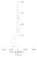
- Fig. 4 a schematic view of a spherical aberration of the first preferred embodiment of the present invention is shown.
- the measured astigmatic aberration, distorted aberration, and spherical aberration are in the standard scope and have a good optical performance and imaging quality according to the above-mentioned figures.
- Basic lens data of the second preferred embodiment Surfaces Curvature radius (Radius) Thickness/In terval (Thickness) Refractivity (Nd) Abbe number (Vd) First lens 10 First surface 11 (the fixing diaphrag m 70) 1.65 0.47 1.5441 56.09 Second surface 12 -2.77 0.17 Second lens 20 Third surface 21 -2.63 0.26 1.635500 23.891420 Fourth surface 22 -31.03 0.11 Third lens 30 Fifth surface 31 -1.59 0.57 1.5441 56.09 Sixth surface 32 -0.48 0.03 Fourth lens 40 Seventh surface 41 1.47 0.30 1.534611 56.072163 Eighth surface 42 0.42 0.27 Filter unit 50 Ninth surface 51 ⁇ 0.30 1.516798 64.198258 Tenth surface 52 ⁇ 0.42
- the filter unit 50 has a thickness of 0.3mm.
- the A, B, C, D, E, F, and G are defined as high-order aspheric surface coefficients.
- the third surface 21 (k -33.48) :
- the fourth surface 22 (k -21.50):
- the first lens 10 includes a first surface 11 facing an object side and a second surface 12 facing the imaging surface side.
- the first surface 11 is defined as a convex surface disposed near the optical axis opposite to the object side.
- the second surface 12 is defined as a convex surface disposed near the optical axis opposite to the imaging surface side.
- the second lens 20 includes a third surface 21 facing the object side and a fourth surface
- the third surface 21 is defined as a concave surface disposed near the optical axis opposite to the object side.
- the fourth surface 22 is defined as a convex surface disposed near the optical axis opposite to the imaging surface side.
- the third lens 30 includes a fifth surface 31 facing the object side and a sixth surface 32 facing the imaging surface side.
- the fifth surface 31 is defined as a concave surface disposed near the optical axis opposite to the object side.
- the sixth surface 32 is defined as a convex surface disposed near the optical axis opposite to the imaging surface side.
- the fourth lens 40 includes a seventh surface 41 facing the object side and an eighth surface 42 facing the imaging surface side.
- the seventh surface 41 is defined as a convex surface disposed near the optical axis opposite to the object side.
- the eighth surface 42 is defined as a concave surface disposed near the optical axis opposite to the imaging surface side.
- At least one surface of the first lens 10 and the second lens 20 is aspheric, and at least one surface of the third lens 30 and the fourth lens 40 are aspheric, thereby correcting the spherical aberration and the image aberration for having a characteristic of low tolerance sensitivity.
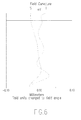
- a schematic view of an astigmatic aberration of the second preferred embodiment of the present invention is shown.
- a schematic view of a distorted aberration of the second preferred embodiment of the present invention is shown.
- a schematic view of a spherical aberration of the second preferred embodiment of the present invention is shown.
- the measured astigmatic aberration, distorted aberration, and spherical aberration are in the standard scope and have a good optical performance and imaging quality according to the above-mentioned figures.
- the micro-optical image capturing device utilizes four lenses which include at least one aspheric surface or two aspheric surfaces with the refractive power sequentially arranged as positive, negative, positive, and negative, and the filter unit 50 which filters a wave length of the light and allows the demanded wave length.
- the filter unit 50 is preferably adopted by an infrared stopping filter unit applied to the visible light image or an infrared band-pass unit applied to an infrared imaging.
- the first, second, third, and fourth lenses are preferably adopted by plastic, which is conducive to eliminate the aberration and reduce the weight of the lens.
- the optical system consists of four plastic lenses and provides with the low tolerance sensitivity.
- the optical system is also easy to be manufactured and assembled and benefits a mass production. Furthermore, the optical system provides with a good imaging quality to meet the requirement of miniaturizing the portable image capturing products.
Landscapes
- Physics & Mathematics (AREA)
- General Physics & Mathematics (AREA)
- Optics & Photonics (AREA)
- Lenses (AREA)
Abstract
Description
- The present invention relates to a thin-type imaging lens assembly with four lenses, in particular to a lens structure attaining a shorter height and a high resolution by curvature, interval and optical parameter between each lens.
- The conventional lens structure adopts an image display lens assembly which is applied to smart phone, tablet PC, cell phone, notebook, and webcam. The electronic products are developed to become lighter, thinner, shorter, and smaller and provide with higher efficiency. A video sensor of the image display lens assembly, such as Charge Coupled Device (CCD) or Complementary Metal Oxide Semiconductor (CMOS), is also developed for more pixels, so the lens structure is ceaselessly developed to be provided with compactness and higher resolution.
- Therefore, the present invention is disclosed in accordance with a lens structure with multi-lens for a demand of the development of the image display lens assembly, especially to an imaging lens assembly of a lens structure with at least two lenses.
- In view of the conventional lens structure that has big volume and lack of efficiency, a thin-type imaging lens assembly with four lenses is disclosed.
- It is an object of the present invention to provide a thin-type imaging lens assembly with four lenses, which comprises a fixing diaphragm and an optical set. The optical set includes a first lens, a second lens, a third lens, and a fourth lens. An arranging order thereof from an object side to an image side is: the first lens with a positive refractive power defined near an optical axis, a convex surface directed toward the object side, and a convex surface directed toward the image side; the second lens with a negative refractive power defined near the optical axis and a concave surface directed toward the object side; the third lens having a lens with a positive refractive power defined near the optical axis, a concave surface directed toward the object side, and a convex surface directed toward the image side; the fourth lens having a negative refractive power defined near the optical axis, a convex surface directed toward the object side and disposed near the optical axis, a concave surface directed toward the image side and disposed near the optical axis, and at least one inflection point defined from the optical axis to an end point of the aspheric surfaces. At least one surface of the first lens and the second lens is aspheric. At least one surface of the third lens and the fourth lens are aspheric. The fixing diaphragm is disposed between an object and the second lens.
- The imaging lens assembly satisfies the following conditional expression: 0.3<f/TL<0.8. The TL is defined as a distance from a top point of the object side surface of the first lens to an imaging surface side. The f is defined as a focal length of the entire lens assembly.
- The imaging lens assembly satisfies the following conditional expression: 0.6<TL/Dg<1.2. The Dg is defined as a length diagonal of a maximum using visual angle of the lens assembly imaged on the imaging surface.
- A shape of the aspheric surface satisfies a formula of:

- The z is defined as a position value about a location at a height of h along a direction of the optical axis referring to a surface top point. The k is defined as a conic constant. The c is a reciprocal of a radius of a curvature. The A, B, C, D, E, F, G, etc. are defined as high-order aspheric surface coefficients.
- The present invention is characterized in that a lens structure attains a big diaphragm with wide-angle, a shorter height, and a high resolution by curvature, interval, and optical parameter between each lens.
-
- Fig. 1
- is a schematic view showing an optical structure of a first preferred embodiment of the present invention;
- Fig. 2
- is a schematic view showing an astigmatic aberration of the first preferred embodiment of the present invention;
- Fig. 3
- is a schematic view showing a distorted aberration of the first preferred embodiment of the present invention;
- Fig. 4
- is a schematic view showing a spherical aberration of the first preferred embodiment of the present invention;
- Fig. 5
- is a schematic view showing an optical structure of a secondpreferred embodiment of the present invention;
- Fig. 6
- is a schematic view showing an astigmatic aberration of the second preferred embodiment of the present invention;
- Fig. 7
- is a schematic view showing a distorted aberration of the second preferred embodiment of the present invention; and
- Fig. 8
- is a schematic view showing a spherical aberration of the second preferred embodiment of the present invention.
- Before describing in detail, it should note that the like elements are denoted by the similar reference numerals throughout disclosure.
- The present invention provides an imaging lens structure, in particular to a lens structure attaining a big diaphragm with wide-angle, a shorter height, and a high resolution by a curvature, an interval, and an optical parameter between each lens.
- Referring to
Fig. 1 , a schematic view of an optical structure of a thin-type imaging lens assembly with four lenses is shown. The structure of the imaging lens comprises afixing diaphragm 70 and an optical set. The optical set includes afirst lens 10, asecond lens 20, athird lens 30, and afourth lens 40. An arranging order thereof from an object side to an image side is: thefirst lens 10 with a positive refractive power defined near an optical axis, a convex surface directed toward the object side, and a convex surface directed toward the image side; thesecond lens 20 with a negative refractive power defined near the optical axis and a concave surface directed toward the object side; thethird lens 30 with a positive refractive power defined near the optical axis, a concave surface directed toward the object side, and a convex surface directed toward the image side; thefourth lens 40 having a negative refractive power defined near the optical axis, a convex surface directed toward the object side and disposed near the optical axis, a concave surface directed toward the image side and disposed near the optical axis, at least one inflection point defined from the optical axis to an end point of the aspheric surfaces, at least one surface of thefirst lens 10 and thesecond lens 20 is aspheric, and at least one surface of thethird lens 30 and thefourth lens 40 are aspheric; thefixing diaphragm 70 disposed between an object and thesecond lens 20; afilter unit 50 used for filtering light with specific wave length being adopted by an infrared stopping filter unit applied to a visible light image or an infrared band-pass unit applied to an infrared imaging; and an image sensor 60 (an imaging surface side) used for receiving a digital signal transformed by an infrared invisible light image of the filter. - The imaging lens assembly satisfies the following conditional expression: 0.3<f/TL<0.8. The TL is defined as a distance from a top point of the object side surface of the first lens to the imaging surface side. The f is defined as a focal length of the entire lens assembly.
- The imaging lens assembly satisfies the following conditional expression: 0.6<TL/Dg<1.2. The Dg is defined as a length diagonal of a maximum using visual angle of the lens assembly imaged on the imaging surface.
- The
first lens 10 includes afirst surface 11 facing an object side and asecond surface 12 facing the imaging surface side. Thefirst surface 11 is defined as a convex surface disposed near the optical axis opposite to the object side. Thesecond surface 12 is defined as a convex surface disposed near the optical axis opposite to the imaging surface side. Thesecond lens 20 includes athird surface 21 facing the object side and afourth surface 22 facing the imaging surface side. Thethird surface 21 is defined as a concave surface disposed near the optical axis opposite to the object side. Thefourth surface 22 is defined as a concave surface disposed near the optical axis opposite to the imaging surface side. Thethird lens 30 includes afifth surface 31 facing the object side and asixth surface 32 facing the imaging surface side. Thefifth surface 31 is defined as a concave surface disposed near the optical axis opposite to the object side. Thesixth surface 32 is defined as a convex surface disposed near the optical axis opposite to the imaging surface side. Thefourth lens 40 includes aseventh surface 41 facing the object side and aneighth surface 42 facing the imaging surface side. Theseventh surface 41 is defined as a convex surface disposed near the optical axis opposite to the object side. Theeighth surface 42 is defined as a concave surface disposed near the optical axis opposite to the imaging surface side. At least one surface of thefirst lens 10 and thesecond lens 20 is aspheric, and at least one surface of thethird lens 30 and thefourth lens 40 are aspheric, thereby correcting the spherical aberration and the image aberration for having a characteristic of low tolerance sensitivity. - A shape of the aspheric surface of the imaging lens assembly satisfies a formula of:

- The z is defined as a position value about a location at a height of h along a direction of the optical axis referring to a surface top point. The k is defined as a conic constant. The c is a reciprocal of a radius of a curvature. The A, B, C, D, E, F, G, etc. are defined as high-order aspheric surface coefficients.
- In a wide-angle micro-optical image capturing device of the present invention, the fixing
diaphragm 70 is disposed between the object and thesecond lens 20 for getting an incident beam. Thefirst lens 10 is adopted by a lens with positive refractive power defined near the optical axis. Thefirst lens 10 adopts thefirst surface 11 convexly defined toward the object side for assembling the external incident beam with wide-angle and keeping the beam on thesecond surface 12 of thefirst lens 10, thereby presenting a function of the aspheric surface, correcting the aberration, reducing the tolerance sensitivity, and rendering the device have big-wide-angle. Thethird surface 21 and thefifth surface 31 respectively defined on thesecond lens 20 and thethird lens 30 as concave surfaces disposed near the optical axis opposite to the object side are then expanded and radiated, so that the beam is able to be spread on theeighth surface 42 of thefourth lens 40 with a larger dimension. That is to say, the incident beam is expanded and radiated by thethird surface 21 and thefifth surface 31 so as to be spread on theeighth surface 42 with a larger dimension, thereby presenting the function of aspheric surface, correcting the aberration, and reducing tolerance sensitivity. - The aspheric surface not only corrects the spherical aberration and the image aberration but also reduces the full length of the lens optical system. The
first lens 10, thesecond lens 20, thethird lens 30, and thefourth lens 40 are preferably adopted by plastic, which is conducive to eliminate the aberration and reduce the weight of the lens. The entire optical system consists of four plastic lenses and benefits a mass production. Furthermore, the optical system provides with the low tolerance sensitivity to meet a requirement of the mass production. - By the concatenation between the above-mentioned surfaces of lenses and the adapted curvature radius, thickness, interval, refractivity, and Abbe numbers, the assembly attains a big diaphragm with wide-angle, a shorter height, and a better optical aberration.
- Due to the above-mentioned technique of the present invention, it is able to be practiced in accordance with the following values:
Basic lens data of the first preferred embodiment Surfaces Curvature radius (Radius) Thickness/In terval (Thickness) Refractivity (Nd) Abbe number (Vd) Fixing diaphragm 70∞ -0.04 First lens 10First surface 111.15 0.32 1.5441 56.09 Second surface 12 -3.31 0.12 Second lens 20Third surface 21 -10.0 0.20 1.635500 23.891420 Fourth surface 223.21 0.07 Third lens 30Fifth surface 31 -1.15 0.37 1.5441 56.09 Sixth surface 32 -0.37 0.03 Fourth lens 40Seventh surface 410.78 0.20 1.534611 56.072163 Eighth surface 420.30 0.20 Filter unit 50Ninth surface 51∞ 0.21 1.516798 64.198258 Tenth surface 52∞ 0.30 - The
filter unit 50 has a thickness of 0.21mm. - The A, B, C, D, E, F, and G are defined as high-order aspheric surface coefficients.
- The values of quadratic surface coefficient of the aspheric surface of the first preferred embodiment are listed as follows:
- The first surface 11 (k=-5.38):
- A: -0.3081197
- B: 16.258579
- C: -496.70534
- D: 7166.1666
- E: -58684.873
- F: 253687.41
- G: -454271.82
- The second surface 12 (k=12.07):
- A: -1.1794601
- B: -9.6792113
- C: 198.62572
- D: -2387.9023
- E: 16554.949
- F: -58551.248
- G: 79979.896
- The third surface 21(k=15.39) :
- A: -1.9294681
- B: -12.954564
- C: 164.41796
- D: -1000.4379
- E: 6390.1008
- F: -24827.633
- G: 36002.667
- The fourth surface 22(k=-200.0) :
- A: 1.7098738
- B: -27.547123
- C: 199.38445
- D: -766.05050
- E: 210.06524
- F: 6640.7099
- G: -12361.994
- The fifth surface 31(k=1.91) :
- A: 3.9392086
- B: -12.649364
- C: -91.632654
- D: 1755.6071
- E: -11903.808
- F: -35996.894
- G: -39951.310
- The sixth surface 32(k=-5.51) :
- A: -4.1854094
- B: 51.437818
- C: -454.48526
- D: 2652.5890
- E: -9019.8863
- F: 16110.841
- G: -11574.730
- The seventh surface 41(k=-3.55) :
- A: -2.4126233
- B: 11.561474
- C: -76.191919
- D: 365.04515
- E: -1027.4361
- F: 1500.2847
- G: -892.37580
- The eighth surface 42(k=-4.24) :
- A: -1.0647050
- B: 2.5299538
- C: -6.3145965
- D: 13.876987
- E: -22.676248
- F: 20.462749
- G: -7.507268
- According to the above-mentioned values, the related exponent of performance of the micro-image capturing lens is: f1=1.60mm; f2=-3.77mm; f3=0.85mm; f4=-1.09mm; EFL=1.31mm; TL=2.01mm; Dg=2.06mm; EFL/TL=0.65; TL/Dg=0.98.
- Referring to
Fig. 2 , a schematic view of an astigmatic aberration of the first preferred embodiment of the present invention is shown. Referring toFig. 3 , a schematic view of a distorted aberration of the first preferred embodiment of the present invention is shown. Referring toFig. 4 , a schematic view of a spherical aberration of the first preferred embodiment of the present invention is shown. The measured astigmatic aberration, distorted aberration, and spherical aberration are in the standard scope and have a good optical performance and imaging quality according to the above-mentioned figures. - Due to the above-mentioned technique of the present invention, it is able to be practiced in accordance with the following values:
Basic lens data of the second preferred embodiment Surfaces Curvature radius (Radius) Thickness/In terval (Thickness) Refractivity (Nd) Abbe number (Vd) First lens 10First surface 11 (the fixing diaphrag m 70) 1.65 0.47 1.5441 56.09 Second surface 12 -2.77 0.17 Second lens 20Third surface 21 -2.63 0.26 1.635500 23.891420 Fourth surface 22 -31.03 0.11 Third lens 30Fifth surface 31 -1.59 0.57 1.5441 56.09 Sixth surface 32 -0.48 0.03 Fourth lens 40Seventh surface 411.47 0.30 1.534611 56.072163 Eighth surface 420.42 0.27 Filter unit 50Ninth surface 51∞ 0.30 1.516798 64.198258 Tenth surface 52∞ 0.42 - The
filter unit 50 has a thickness of 0.3mm. - The A, B, C, D, E, F, and G are defined as high-order aspheric surface coefficients.
- The values of quadratic surface coefficient of the aspheric surface of the second preferred embodiment are listed as follows:
- The first surface 11 (k=-4.46):
- A: -0.11793308
- B: 2.312182
- C: -36.511014
- D: 252.50961
- E: -982.12147
- F: 1977.7645
- G: -1632.3527
- The second surface 12(k=-25.37) :
- A: -0.42555237
- B: -3.0752288
- C: 27.501249
- D: -151.17332
- E: 489.54646
- F: -853.89616
- G: 611.88916
- The third surface 21(k=-33.48) :
- A: -0.67729382
- B: -1.7819054
- C: 4.9864964
- D: 18.095894
- E: -84.626763
- F: 127.86346
- G: -63.68553
- The fourth surface 22(k=-21.50):
- A: 0.37431509
- B: -3.6299761
- C: 11.722422
- D: -22.943566
- E: 21.701385
- F: 2.1034529
- G: -11.217456
- The fifth surface 31(k=1.89):
- A: 0.97399538
- B: -1.9572256
- C: -4.0805823
- D: 39.177621
- E: -110.4093
- F: 150.28777 G: -80.024502
- The sixth surface 32(k=-5.58) :
- A: -2.0330788
- B: 11.699186
- C: -45.519288
- D: 110.24445
- E: -157.17487
- F: 123.57382
- G: -41.482307
- The seventh surface 41(k=-2.20) :
- A: -1.000893
- B: 2.4063511
- C: -6.8590943
- D: 13.267147
- E: -15.419277
- F: 9.8360708
- G: -2.8306765
- The eighth surface 42(k=-4.48) :
- A: -0.41774612
- B: 0.68438911
- C: -1.1364654
- D: 1.3167622
- E: -0.93961956
- F: 0.35833015
- G: -0.055820864
- According to the above-mentioned values, the related exponent of performance of the micro-image capturing lens is: f1=1.97mm; f2=-4.51mm; f3=1.06mm; f4=-1.20mm; EFL=1.87mm; TL=3.00mm; Dg=2.94mm; EFL/TL=0.62; TL/Dg=1.02.
- In the second preferred embodiment of the present invention, the
first lens 10 includes afirst surface 11 facing an object side and asecond surface 12 facing the imaging surface side. Thefirst surface 11 is defined as a convex surface disposed near the optical axis opposite to the object side. Thesecond surface 12 is defined as a convex surface disposed near the optical axis opposite to the imaging surface side. Thesecond lens 20 includes athird surface 21 facing the object side and a fourth surface - 22 facing the imaging surface side. The
third surface 21 is defined as a concave surface disposed near the optical axis opposite to the object side. Thefourth surface 22 is defined as a convex surface disposed near the optical axis opposite to the imaging surface side. Thethird lens 30 includes afifth surface 31 facing the object side and asixth surface 32 facing the imaging surface side. Thefifth surface 31 is defined as a concave surface disposed near the optical axis opposite to the object side. Thesixth surface 32 is defined as a convex surface disposed near the optical axis opposite to the imaging surface side. Thefourth lens 40 includes aseventh surface 41 facing the object side and aneighth surface 42 facing the imaging surface side. Theseventh surface 41 is defined as a convex surface disposed near the optical axis opposite to the object side. Theeighth surface 42 is defined as a concave surface disposed near the optical axis opposite to the imaging surface side. At least one surface of thefirst lens 10 and thesecond lens 20 is aspheric, and at least one surface of thethird lens 30 and thefourth lens 40 are aspheric, thereby correcting the spherical aberration and the image aberration for having a characteristic of low tolerance sensitivity. - Referring to
Fig. 6 , a schematic view of an astigmatic aberration of the second preferred embodiment of the present invention is shown. Referring toFig. 7 , a schematic view of a distorted aberration of the second preferred embodiment of the present invention is shown. Referring toFig. 8 , a schematic view of a spherical aberration of the second preferred embodiment of the present invention is shown. The measured astigmatic aberration, distorted aberration, and spherical aberration are in the standard scope and have a good optical performance and imaging quality according to the above-mentioned figures. - The micro-optical image capturing device utilizes four lenses which include at least one aspheric surface or two aspheric surfaces with the refractive power sequentially arranged as positive, negative, positive, and negative, and the
filter unit 50 which filters a wave length of the light and allows the demanded wave length. Thefilter unit 50 is preferably adopted by an infrared stopping filter unit applied to the visible light image or an infrared band-pass unit applied to an infrared imaging. - By making use of the aspheric surface that corrects the aberration and reduces the tolerance sensitivity, not only the aberration is corrected but also the full length of the lens optical system is reduced. The first, second, third, and fourth lenses are preferably adopted by plastic, which is conducive to eliminate the aberration and reduce the weight of the lens. The optical system consists of four plastic lenses and provides with the low tolerance sensitivity. The optical system is also easy to be manufactured and assembled and benefits a mass production. Furthermore, the optical system provides with a good imaging quality to meet the requirement of miniaturizing the portable image capturing products.
- While we have shown and described the embodiment in accordance with the present invention, it should be clear to those skilled in the art that further embodiments may be made without departing from the scope of the present invention.
Claims (3)
- A thin-type imaging lens assembly with four lenses comprising a fixing diaphragm (70) and an optical set; said optical set including a first lens (10), a second lens (20), a third lens (30), and a fourth lens (40), an arranging order thereof from an object side to an image side being:said first lens (10) having a positive refractive power defined near an optical axis, a convex surface directed toward said object side, and a convex surface directed toward said image side; at least one surface of said first lens (10) being aspheric;said second lens (20) having a negative refractive power defined near said optical axis and a concave surface directed toward said object side; at least one surface of said second lens (20) being aspheric;said third lens (30) having a lens with a positive refractive power defined near said optical axis, a concave surface directed toward said object side, and a convex surface directed toward said image side; at least one surface of said third lens (30) being aspheric;said fourth lens (40) with a negative refractive power defined near said optical axis, a convex surface directed toward said object side and disposed near said optical axis, and a concave surface directed toward said image side and disposed near said optical axis; at least one surface of said fourth lens (40) being aspheric and having at least one inflection point defined from said optical axis to an end point of said aspheric surfaces; andsaid fixing diaphragm (70) disposed between an object and said second lens.
- The thin-type imaging lens assembly with four lenses as claimed in claim 1 further satisfying the following expression: 0.3<f/TL<0.8, wherein said TL is defined as a distance from a top point of said object side surface of said first lens (10) to an imaging surface side, and said f is defined as a focal length of said entire lens assembly.
- The thin-type imaging lens assembly with four lenses as claimed in claim 1 further satisfying the following conditional expression: 0.6<TL/Dg<1.2, wherein said Dg is defined as a length diagonal of a maximum using visual angle of the lens assembly imaged on said imaging surface.
Applications Claiming Priority (1)
| Application Number | Priority Date | Filing Date | Title |
|---|---|---|---|
| TW102212968U TWM474142U (en) | 2013-07-09 | 2013-07-09 | Thinned four-piece imaging lens module |
Publications (2)
| Publication Number | Publication Date |
|---|---|
| EP2824494A2 true EP2824494A2 (en) | 2015-01-14 |
| EP2824494A3 EP2824494A3 (en) | 2015-03-11 |
Family
ID=49474283
Family Applications (1)
| Application Number | Title | Priority Date | Filing Date |
|---|---|---|---|
| EP13190026.8A Withdrawn EP2824494A3 (en) | 2013-07-09 | 2013-10-24 | A thin-type imaging lens assembly with four lenses |
Country Status (4)
| Country | Link |
|---|---|
| US (1) | US20150015972A1 (en) |
| EP (1) | EP2824494A3 (en) |
| CN (1) | CN203385928U (en) |
| TW (1) | TWM474142U (en) |
Families Citing this family (9)
| Publication number | Priority date | Publication date | Assignee | Title |
|---|---|---|---|---|
| CN103969791B (en) * | 2013-12-09 | 2016-05-25 | 玉晶光电(厦门)有限公司 | Optical imaging lens and apply the electronic installation of this camera lens |
| US9864168B2 (en) * | 2014-06-23 | 2018-01-09 | Genius Electronic Optical Co., Ltd. | Near-infrared lens for cameras in mobile devices |
| CN105866934B (en) * | 2015-01-23 | 2018-07-13 | 先进光电科技股份有限公司 | Four-piece type imaging lens group |
| TWI580997B (en) * | 2015-05-15 | 2017-05-01 | 先進光電科技股份有限公司 | Optical image capturing system |
| CN105487202B (en) * | 2015-12-31 | 2018-02-02 | 福建师范大学 | The four-piece type optical shooting lens and its imaging method for the angle of visual field of being grown up with short mirror |
| JP6268208B2 (en) * | 2016-02-24 | 2018-01-24 | エーエーシー テクノロジーズ ピーティーイー リミテッドAac Technologies Pte.Ltd. | Imaging lens |
| TWI638200B (en) * | 2017-01-04 | 2018-10-11 | 先進光電科技股份有限公司 | Optical image capturing system |
| JP6434066B2 (en) | 2017-01-23 | 2018-12-05 | カンタツ株式会社 | Imaging lens |
| CN113341542B (en) * | 2021-06-24 | 2022-11-11 | 浙江舜宇光学有限公司 | Optical imaging lens |
Family Cites Families (11)
| Publication number | Priority date | Publication date | Assignee | Title |
|---|---|---|---|---|
| JP4466713B6 (en) * | 2003-11-13 | 2024-03-11 | コニカミノルタオプト株式会社 | Imaging lens and imaging device |
| WO2008078709A1 (en) * | 2006-12-22 | 2008-07-03 | Seiko Precision Inc. | Imaging lens, imaging device using the imaging lens, and portable terminal device |
| CN101373256B (en) * | 2007-08-22 | 2010-04-21 | 鸿富锦精密工业(深圳)有限公司 | Imaging lens |
| US20090185292A1 (en) * | 2008-01-17 | 2009-07-23 | Newmax Technology Co. Ltd. | Imaging lens module |
| CN101755230B (en) * | 2008-02-13 | 2011-12-07 | 纳卢克斯株式会社 | Imaging Optical System |
| TWI384254B (en) * | 2008-10-16 | 2013-02-01 | Largan Precision Co Ltd | Optical lens system for taking image |
| TWI406004B (en) * | 2009-02-19 | 2013-08-21 | Largan Precision Co Ltd | Imaging optical lens assembly |
| TWI391701B (en) * | 2009-09-30 | 2013-04-01 | Largan Precision Co Ltd | Imaging lens assembly |
| TWI407140B (en) * | 2009-12-24 | 2013-09-01 | Largan Precision Co Ltd | Photographing lens assembly |
| TW201211614A (en) * | 2010-09-10 | 2012-03-16 | Genius Electronic Optical Co Ltd | Imaging lens composed of four lenses and electronic device using the same |
| JP2012073535A (en) * | 2010-09-29 | 2012-04-12 | Sony Corp | Imaging lens and imaging apparatus |
-
2013
- 2013-07-09 TW TW102212968U patent/TWM474142U/en not_active IP Right Cessation
- 2013-08-06 CN CN201320477792.2U patent/CN203385928U/en not_active Expired - Lifetime
- 2013-10-15 US US14/054,172 patent/US20150015972A1/en not_active Abandoned
- 2013-10-24 EP EP13190026.8A patent/EP2824494A3/en not_active Withdrawn
Non-Patent Citations (1)
| Title |
|---|
| None |
Also Published As
| Publication number | Publication date |
|---|---|
| US20150015972A1 (en) | 2015-01-15 |
| EP2824494A3 (en) | 2015-03-11 |
| CN203385928U (en) | 2014-01-08 |
| TWM474142U (en) | 2014-03-11 |
Similar Documents
| Publication | Publication Date | Title |
|---|---|---|
| EP2824494A2 (en) | A thin-type imaging lens assembly with four lenses | |
| CN107505686B (en) | Optical image pickup system and image pickup device | |
| KR101503396B1 (en) | Lens system | |
| US20140307336A1 (en) | Thin-type wide-angle imaging lens assembly with three lenses | |
| CN103502868A (en) | Imaging lens and imaging device provided with the imaging lens | |
| US8422151B2 (en) | Wide-angle imaging lens module | |
| US20030210341A1 (en) | Taking lens system | |
| CN105676426A (en) | Imaging lens | |
| EP2793064A1 (en) | A wide-angle imaging assembly with five lenses | |
| KR20130043928A (en) | Imaging lens | |
| US9661199B2 (en) | Imaging apparatus and electronic device which can be reduced in height | |
| CN106199914A (en) | Imaging lens assembly and image capturing device | |
| US20110194019A1 (en) | Optical imaging lens and array thereof | |
| EP2796912A2 (en) | A thin-type wide-angle imaging lens assembly with five lenses | |
| EP2821833A1 (en) | An ultra-wide-angle imaging lens assembly with five lenses | |
| EP2816387A1 (en) | A wide-angle imaging lens assembly with two lenses | |
| US7933077B1 (en) | Wide-angle imaging lens module | |
| EP2796913A2 (en) | An imaging lens assembly with five lenses | |
| US20140376111A1 (en) | Wide-angle imaging lens assembly with three lenses | |
| CN100538423C (en) | Minisize image acquisition lens | |
| EP2796911A1 (en) | A thin-type wide-angle imaging lens assembly with four lenses | |
| CN113281884A (en) | Optical lens, camera module and electronic equipment | |
| CN215416071U (en) | Optical lens, camera module and electronic equipment | |
| CN213365163U (en) | Optical lens, lens module and electronic equipment | |
| US8077399B1 (en) | Four-piece imaging lens module |
Legal Events
| Date | Code | Title | Description |
|---|---|---|---|
| 17P | Request for examination filed |
Effective date: 20131024 |
|
| AK | Designated contracting states |
Kind code of ref document: A2 Designated state(s): AL AT BE BG CH CY CZ DE DK EE ES FI FR GB GR HR HU IE IS IT LI LT LU LV MC MK MT NL NO PL PT RO RS SE SI SK SM TR |
|
| AX | Request for extension of the european patent |
Extension state: BA ME |
|
| PUAI | Public reference made under article 153(3) epc to a published international application that has entered the european phase |
Free format text: ORIGINAL CODE: 0009012 |
|
| PUAL | Search report despatched |
Free format text: ORIGINAL CODE: 0009013 |
|
| AK | Designated contracting states |
Kind code of ref document: A3 Designated state(s): AL AT BE BG CH CY CZ DE DK EE ES FI FR GB GR HR HU IE IS IT LI LT LU LV MC MK MT NL NO PL PT RO RS SE SI SK SM TR |
|
| AX | Request for extension of the european patent |
Extension state: BA ME |
|
| RIC1 | Information provided on ipc code assigned before grant |
Ipc: G02B 13/00 20060101AFI20150203BHEP |
|
| STAA | Information on the status of an ep patent application or granted ep patent |
Free format text: STATUS: THE APPLICATION IS DEEMED TO BE WITHDRAWN |
|
| 18D | Application deemed to be withdrawn |
Effective date: 20150912 |