EP2824160A1 - Outdoor luminaire - Google Patents
Outdoor luminaire Download PDFInfo
- Publication number
- EP2824160A1 EP2824160A1 EP14173102.6A EP14173102A EP2824160A1 EP 2824160 A1 EP2824160 A1 EP 2824160A1 EP 14173102 A EP14173102 A EP 14173102A EP 2824160 A1 EP2824160 A1 EP 2824160A1
- Authority
- EP
- European Patent Office
- Prior art keywords
- phosphor
- luminaire
- wavelength
- resin
- phosphor layer
- Prior art date
- Legal status (The legal status is an assumption and is not a legal conclusion. Google has not performed a legal analysis and makes no representation as to the accuracy of the status listed.)
- Withdrawn
Links
Images



Classifications
-
- F—MECHANICAL ENGINEERING; LIGHTING; HEATING; WEAPONS; BLASTING
- F21—LIGHTING
- F21K—NON-ELECTRIC LIGHT SOURCES USING LUMINESCENCE; LIGHT SOURCES USING ELECTROCHEMILUMINESCENCE; LIGHT SOURCES USING CHARGES OF COMBUSTIBLE MATERIAL; LIGHT SOURCES USING SEMICONDUCTOR DEVICES AS LIGHT-GENERATING ELEMENTS; LIGHT SOURCES NOT OTHERWISE PROVIDED FOR
- F21K9/00—Light sources using semiconductor devices as light-generating elements, e.g. using light-emitting diodes [LED] or lasers
- F21K9/60—Optical arrangements integrated in the light source, e.g. for improving the colour rendering index or the light extraction
- F21K9/64—Optical arrangements integrated in the light source, e.g. for improving the colour rendering index or the light extraction using wavelength conversion means distinct or spaced from the light-generating element, e.g. a remote phosphor layer
-
- H—ELECTRICITY
- H10—SEMICONDUCTOR DEVICES; ELECTRIC SOLID-STATE DEVICES NOT OTHERWISE PROVIDED FOR
- H10H—INORGANIC LIGHT-EMITTING SEMICONDUCTOR DEVICES HAVING POTENTIAL BARRIERS
- H10H20/00—Individual inorganic light-emitting semiconductor devices having potential barriers, e.g. light-emitting diodes [LED]
- H10H20/80—Constructional details
- H10H20/85—Packages
- H10H20/851—Wavelength conversion means
-
- C—CHEMISTRY; METALLURGY
- C09—DYES; PAINTS; POLISHES; NATURAL RESINS; ADHESIVES; COMPOSITIONS NOT OTHERWISE PROVIDED FOR; APPLICATIONS OF MATERIALS NOT OTHERWISE PROVIDED FOR
- C09K—MATERIALS FOR MISCELLANEOUS APPLICATIONS, NOT PROVIDED FOR ELSEWHERE
- C09K11/00—Luminescent materials, e.g. electroluminescent or chemiluminescent
- C09K11/08—Luminescent materials, e.g. electroluminescent or chemiluminescent containing inorganic luminescent materials
- C09K11/77—Luminescent materials, e.g. electroluminescent or chemiluminescent containing inorganic luminescent materials containing rare earth metals
- C09K11/7715—Luminescent materials, e.g. electroluminescent or chemiluminescent containing inorganic luminescent materials containing rare earth metals containing cerium
-
- C—CHEMISTRY; METALLURGY
- C09—DYES; PAINTS; POLISHES; NATURAL RESINS; ADHESIVES; COMPOSITIONS NOT OTHERWISE PROVIDED FOR; APPLICATIONS OF MATERIALS NOT OTHERWISE PROVIDED FOR
- C09K—MATERIALS FOR MISCELLANEOUS APPLICATIONS, NOT PROVIDED FOR ELSEWHERE
- C09K11/00—Luminescent materials, e.g. electroluminescent or chemiluminescent
- C09K11/08—Luminescent materials, e.g. electroluminescent or chemiluminescent containing inorganic luminescent materials
- C09K11/77—Luminescent materials, e.g. electroluminescent or chemiluminescent containing inorganic luminescent materials containing rare earth metals
- C09K11/7766—Luminescent materials, e.g. electroluminescent or chemiluminescent containing inorganic luminescent materials containing rare earth metals containing two or more rare earth metals
- C09K11/7774—Aluminates
-
- F—MECHANICAL ENGINEERING; LIGHTING; HEATING; WEAPONS; BLASTING
- F21—LIGHTING
- F21K—NON-ELECTRIC LIGHT SOURCES USING LUMINESCENCE; LIGHT SOURCES USING ELECTROCHEMILUMINESCENCE; LIGHT SOURCES USING CHARGES OF COMBUSTIBLE MATERIAL; LIGHT SOURCES USING SEMICONDUCTOR DEVICES AS LIGHT-GENERATING ELEMENTS; LIGHT SOURCES NOT OTHERWISE PROVIDED FOR
- F21K9/00—Light sources using semiconductor devices as light-generating elements, e.g. using light-emitting diodes [LED] or lasers
- F21K9/60—Optical arrangements integrated in the light source, e.g. for improving the colour rendering index or the light extraction
-
- H—ELECTRICITY
- H10—SEMICONDUCTOR DEVICES; ELECTRIC SOLID-STATE DEVICES NOT OTHERWISE PROVIDED FOR
- H10H—INORGANIC LIGHT-EMITTING SEMICONDUCTOR DEVICES HAVING POTENTIAL BARRIERS
- H10H20/00—Individual inorganic light-emitting semiconductor devices having potential barriers, e.g. light-emitting diodes [LED]
- H10H20/80—Constructional details
- H10H20/85—Packages
- H10H20/851—Wavelength conversion means
- H10H20/8511—Wavelength conversion means characterised by their material, e.g. binder
- H10H20/8512—Wavelength conversion materials
-
- F—MECHANICAL ENGINEERING; LIGHTING; HEATING; WEAPONS; BLASTING
- F21—LIGHTING
- F21Y—INDEXING SCHEME ASSOCIATED WITH SUBCLASSES F21K, F21L, F21S and F21V, RELATING TO THE FORM OR THE KIND OF THE LIGHT SOURCES OR OF THE COLOUR OF THE LIGHT EMITTED
- F21Y2115/00—Light-generating elements of semiconductor light sources
- F21Y2115/10—Light-emitting diodes [LED]
Definitions
- This invention relates to an outdoor luminaire suitable for installation in those areas that are dim or dark at night or where least lamps are available, for example, pathways, roadways, plazas, residential areas, and tunnels.
- LED lamps are of greater interest, because the LED lamps are advantageous in power consumption and lifetime over traditional incandescent lamps and fluorescent lamps.
- LED lamps come with a wide variation of light emission.
- blue LED lamps that produce light including a blue component may be used as the light source for outdoor luminaires, typically blue streetlights which are nowadays in widespread use.
- the power utility efficiency of LED lamps is very high.
- the power necessary for LED lamps to provide an equivalent illuminance is as low as 1/5 or less of the power consumed by incandescent lamps.
- LED lamps are generally believed to have a lifetime of several tens of thousands of hours, leading to savings of labor and cost for maintenance services. For these reasons, LED lamps are suited for use in streetlights and other outdoor luminaires which are intended for long-term continuous operation.
- White LED packages for general lighting application have a structure in which a phosphor is coated on a front surface of a blue LED chip having emission wavelength of 440 to 470 nm, or a phosphor layer is disposed immediately forward of a blue LED chip in the emission direction. With this structure, blue light is irradiated from the chip to the phosphor, which in turn, emits broad luminescent light having a peak wavelength around 550 nm, which is combined with blue light of unconverted wavelength to produce white light.
- White LED lamps for most luminaires utilize luminescent light having a peak wavelength of about 550 nm because human eyes have a high sensitivity to light of wavelength near 555 nm. In principle, light rich in this wavelength component provides highly effective lighting.
- Non-Patent Document 1 Under scotopic and mesopic vision conditions, among outdoor luminaires using white LEDs, those having an emission peak shifted to a wavelength shorter than 555 nm are preferred. For night lighting, luminaires having a high color temperature are under study (Non-Patent Document 1). These prior art night-lighting luminaires are not regarded as complying with a change of visual sensitivity based on the Purkinje effect because the light does not fully contain wavelength components of the highest visual sensitivity at the scotopic and mesopic vision levels.
- Patent Document 1 JP-A 2008-135381 ( USP 8267541 , EP 2088362 )
- Patent Document 2 JP-A 2009-151967
- Patent Document 3 JP-A 2012-038504
- Patent Document 4 JP-A 2012-009434
- Non-Patent Document 1 Shirokura et al., "Influence on spatial brightness of spectral characteristics of streetlights", Journal of the Illuminating Engineering Institute of Japan, Vol. 96, No. 5, 259-271 (2012 )
- An object of the invention is to provide an outdoor luminaire which produces illumination affording good or improved brightness of lighting and visual perception and brightness over a broad range especially under scotopic and mesopic vision conditions such as often encountered in suburbs, national districts, rural districts and tunnels.
- street-lighting systems employ an increasing number of blue streetlights which are constructed by covering a fluorescent lamp with a blue cover so as to produce light of cold color. That is, the effect of cold color light like blue light, exerting certain tranquillity or sedation to human psychology, is utilized for the security light.
- LED streetlights are merely designed so as to increase the quantity of blue light, without taking into account the visual sensitivity under scotopic and mesopic vision conditions.
- the inventors looked to develop LED lighting that could mitigate a lowering of visual perception due to a change of visual sensitivity (or luminosity) wavelength under scotopic and mesopic vision conditions. Focusing on Lu 3 Al 5 O 12 : Ce 3+ phosphor (LuAG phosphor) for use with blue LED as the light source/phosphor combination, the inventors made a study to improve the brightness perception and visual perception under scotopic and mesopic vision conditions of an LED lighting based on a combination of blue LED with LuAG phosphor.
- the LuAG phosphor is a yellowish green luminescent phosphor capable of emitting luminescent light having a peak wavelength of 520 to 560 nm in response to blue light.
- Y 3 Al 5 O 12 : Ce 3+ (YAG phosphor) having a similar structure to the LuAG phosphor, part of Al is replaced by Ga in order to acquire emission of shorter wavelength, but at the sacrifice of quantum efficiency of the phosphor. It may be contemplated to replace part of Al by Ga in LuAG phosphor. However, such replacement is undesirable for lighting applications because a lowering of quantum efficiency of the phosphor is expected.
- the emission of LuAG phosphor has a spectrum of two overlapping emission profiles rather than a single emission profile, and the two emission profiles are assigned to 5d ⁇ 2 F 5/2 transition (emission peak on the shorter wavelength side) and 5d ⁇ 2 F 7/2 transition (emission peak on the longer wavelength side) of Ce 3+ ion
- the inventors presumed that if the emission profiles are controlled, the quantity of light emission of shorter wavelength might be increased and as a result, lighting suitable for use under scotopic and mesopic vision conditions might be available.
- the inventors have found that for LuAG phosphor, the probabilities of 5d ⁇ 2 F 5/2 transition (emission peak on the shorter wavelength side) and 5d ⁇ 2 F 7/2 transition (emission peak on the longer wavelength side) of Ce 3+ ion are governed by the concentration of Ce; that by controlling the Ce concentration, the probability of 5d ⁇ 2 F 5/2 transition can be increased whereby the quantity of light emission near 510 nm having a high visual sensitivity under scotopic and mesopic vision conditions can be increased; and that by combining LuAG phosphor with blue LED, lighting suitable as outdoor lighting or night lighting is available.
- the invention provides an outdoor luminaire comprising a blue LED chip having a maximum peak at a wavelength of 420 to 480 nm and a phosphor layer disposed forward of the LED chip in its emission direction.
- the phosphor layer comprises a phosphor mixed and dispersed in a resin, and the phosphor has the compositional formula (1): Lu 3 Al 5 O 12 :Ce 3+ (1) and a Ce-activation rate relative to Lu of up to 1 mol%.
- the resin may be a silicone resin or epoxy resin.
- the resin may be at least one thermoplastic resin selected from among polyethylene, polypropylene, polyvinyl chloride, polyethylene terephthalate, polycarbonate, polystyrene, and ABS resins.
- the luminaire provides light having an intensity S1 at wavelength 510 nm and an intensity S2 at wavelength 545 nm, wherein the ratio of S1/S2 is preferably at least 0.95.
- One aspect of the invention is an outdoor luminaire (lighting equipment, light fixture) comprising a blue LED chip having a maximum peak in the wavelength range of 420 to 480 nm.
- the blue LED chip may be a well-known blue LED package in which a blue LED chip, wirings and the like are sealed with an encapsulant. Any well-known or commercially available blue LED package may be used. Those blue LED chips having a maximum peak at a shorter or longer wavelength than the wavelength range defined above are undesirable because the excitation efficiency of phosphor is extremely reduced.
- the outdoor luminaire also comprises a phosphor layer which is disposed forward of the blue LED chip in its emission direction.
- the phosphor layer has a phosphor mixed and dispersed in a resin, the phosphor having the compositional formula (1): Lu 3 Al 5 O 12 :Ce 3+ (1) and a Ce-activation rate relative to Lu (i.e. a proportion of Ce, based on the sum of Lu and Ce) of up to 1 mol%, preferably at least 0.1 mol%.
- This phosphor is often referred to as "LuAG phosphor.”
- the phosphor layer contains at least 0.1% by weight and up to 50% by weight of the LuAG phosphor of formula (1).
- the Ce-activation rate relative to Lu exceeds 1 mol%, a proportion of 5d ⁇ 2 F 7/2 transition becomes higher than a proportion of 5d ⁇ 2 F 5/2 transition, the peak position of emission spectrum shifts toward the longer wavelength side, and the emission wavelength largely deviates from the visual sensitivity under scotopic or mesopic vision, resulting in lighting with poor brightness under scotopic or mesopic vision. If the Ce-activation rate relative to Lu is less than 0.1 mol%, the phosphor itself may have a poor absorptivity with the risk that light near wavelength 510 nm, giving bright perception under scotopic or mesopic vision, may become short.
- the LuAG phosphor used herein is in particulate form.
- the phosphor particles preferably have an average particle size of 1.5 to 50 microns ( ⁇ m). If the average particle size is less than 1.5 ⁇ m, the emission efficiency of phosphor may lower, with a drop of lighting efficiency. If the average particle size exceeds 50 ⁇ m, this raises no problems with respect to lighting characteristics, but a larger amount of phosphor must be used to increase the number of particles, undesirably leading to an increased cost.
- the particle size of phosphor particles may be determined, for example, by dispersing phosphor particles in a gas or water stream and measuring their size by the laser diffraction scattering method.
- the LuAG phosphor used herein may be prepared by well-known methods. For example, lutetium oxide, cerium oxide and aluminum oxide in powder form are mixed in such amounts as to meet the desired composition. Barium fluoride is added thereto as a flux. The powder mixture is heated at a high temperature in air, an inert atmosphere (e.g., nitrogen) or reducing atmosphere (e.g. argon partly replaced by hydrogen) to form a complex oxide, which is disintegrated on a ball mill or the like to an appropriate size.
- an inert atmosphere e.g., nitrogen
- reducing atmosphere e.g. argon partly replaced by hydrogen
- a phosphor other than the LuAG phosphor of formula (1) may be used, e.g. for the purposes of improving the tone and color rendering of outdoor lighting, as long as the present function is still provided.
- the resin of the phosphor layer may be either transparent or semi-transparent.
- silicone resins and epoxy resins may be used.
- the phosphor layer may be formed by mixing and dispersing phosphor particles in an uncured resin composition, applying the resin composition to the surface of a blue LED chip or package, and curing the resin composition.
- a phosphor-loaded resin composition may be molded and cured to form a phosphor layer, which is disposed forward of a blue LED chip or package in its emission direction.
- the resin of the phosphor layer is a thermoplastic resin selected from among polyethylene, polypropylene, polyvinyl chloride, polyethylene terephthalate, polycarbonate, polystyrene, and ABS resin, alone or in admixture of two or more.
- a thermoplastic resin selected from among polyethylene, polypropylene, polyvinyl chloride, polyethylene terephthalate, polycarbonate, polystyrene, and ABS resin, alone or in admixture of two or more.
- a phosphor layer may be formed by milling phosphor particles with the thermoplastic resin to disperse the phosphor in the resin, and molding the resin, and the phosphor layer be disposed forward of a blue LED chip or package in its emission direction.
- any well-known molding methods such as compression molding, extrusion molding and injection molding may be used.
- the material may be molded to any desired shape such as film or thin plate and to any desired size.
- the shape and size of the phosphor layer may be selected as appropriate depending on the application form of the phosphor layer.
- the thickness of the phosphor layer is in a range of about 0.5 to 3 mm, though not particularly limited.
- additives may be used in the phosphor layer as long as the effect of the invention is still achieved.
- Suitable additives include auxiliary agents for improving weather resistance or preventing UV-induced degradation, such as radical scavengers and antioxidants, and light scattering agents for promoting light scattering, such as silica and talc.
- the content of such additive is typically up to 10% by weight, preferably 0.01 to 5% by weight of the phosphor layer.
- the outdoor luminaire takes the form of remote phosphor type in which the phosphor layer, especially a said phosphor layer based on a thermoplastic resin, is spaced apart from the blue LED package via a gas or vacuum layer.
- the luminaire of remote phosphor type has luminous intensity distribution characteristics different from general LED lamps, typically surface emission and a large radiation angle, it is particularly suited as the luminaire intended to provide illumination over a broad area.
- the luminaire is suitable for installation in those areas with less brightness at night or where least light is available nearby, for example, pathways, roadways, plazas, residential areas, and tunnels. It is suitable for outdoor use, typically as streetlight. It may also be used indoors if the indoor area is in a similar dark environment, because it is suitable for use in scotopic and mesopic vision conditions. That is, the outdoor luminaire is one suitable for outdoor use, or is one actually outdoors.
- a powder mixture 1,000 g, was obtained by mixing lutetium oxide (Lu 2 O 3 ) powder of 99.9% purity having an average particle size of 1.0 ⁇ m, aluminum oxide (Al 2 O 3 ) powder of 99.0% purity having an average particle size of 0.5 ⁇ m, and cerium oxide (CeO 2 ) powder of 99.9% purity having an average particle size of 0.2 ⁇ m in a molar ratio Lu:Al:Ce of 2.97:5.0:0.03.
- Barium fluoride, 200 g, as flux was added to the powder mixture, which was thoroughly mixed. The mixture was placed in an alumina crucible and heat treated in argon gas at 1,400°C for 10 hours.
- FIG. 1 The result of XRD analysis of the phosphor particles is shown in FIG. 1 .
- the diffraction pattern of main phase of the phosphor particles is coincident with the diffraction peaks of lutetium aluminum garnet phase, demonstrating that Lu 3 Al 5 O 12 : Ce 3+ containing garnet phase as main phase is obtained.
- the Lu 3 Al 5 O 12 : Ce 3+ phosphor particles were dispersed in a transparent epoxy resin (SpeciFix-40 kit by Marumoto Struers K.K.) to form a slurry having a phosphor concentration of 20 wt%.
- the slurry was added dropwise to the emissive surface of a blue LED package (NS6b083T by Nichia Corp.) and cured at 50°C for 3 hours, completing an LED package having a phosphor layer containing phosphor particles mixed and dispersed in epoxy resin.
- LED packages thus manufactured were arranged in a rectangular aluminum chassis of 39 mm wide, 220 mm long, and 30 mm deep (inside size) and connected in series.
- a transparent matt acrylic plate of 2 mm thick as a protective cover was attached at a position spaced 25 mm apart from the emissive surface of the LED packages.
- An LED luminaire was fabricated as shown in FIG. 2 , wherein LED packages 1, aluminum chassis 2, protective cover 3, power supply terminals 4, and power switch 5 are depicted.
- the spectrum of illuminating light of the LED luminaire was measured by an illuminance spectrophotometer CL-500 (Konica Minolta, Inc.). The result is shown in FIG. 3 .
- an intensity S1 at wavelength 510 nm and an intensity S2 at wavelength 545 nm were measured, from which a ratio S1/S2 was calculated to be 1.076.
- a powder mixture 1,000 g, was obtained by mixing yttrium oxide (Y 2 O 3 ) powder of 99.9% purity having an average particle size of 1.0 ⁇ m, aluminum oxide (Al 2 O 3 ) powder of 99.0% purity having an average particle size of 0.5 ⁇ m, and cerium oxide (CeO 2 ) powder of 99.9% purity having an average particle size of 0.2 ⁇ m in a molar ratio Y:Al:Ce of 2.94:5.0:0.06.
- Barium fluoride, 200 g, as flux was added to the powder mixture, which was thoroughly mixed. The mixture was placed in an alumina crucible and heat treated in argon gas at 1,400°C for 10 hours.
- the fired product was disintegrated on a ball mill, washed with about 0.5 mol/L hydrochloric acid and then with deionized water. Subsequent solid/liquid separation and drying yielded Y 3 Al 5 O 12 : Ce 3+ phosphor particles having an average particle size of 20 ⁇ m.
- An LED package with a phosphor layer was manufactured as in Example 1 except that the Lu 3 Al 5 O 12 : Ce 3+ phosphor particles in Example 1 and the Y 3 Al 5 O 12 : Ce 3+ phosphor particles in Example 2 were dispersed in the transparent epoxy resin in an amount of 15 wt% and 5 wt%, respectively. Using the packages, an LED luminaire was similarly fabricated.
- the spectrum of illuminating light of the LED luminaire was measured as in Example 1.
- the intensity ratio S1/S2 was 0.983.
- Example 1 Seven blue LED packages (XLamp LX-E Royal Blue by Cree Inc.) were arranged in an aluminum chassis and connected in series as in Example 1.
- the Lu 3 Al 5 O 12 : Ce 3+ phosphor particles in Example 1 were kneaded in polycarbonate in a phosphor concentration of 5 wt%, and the resulting PC compound was molded into a PC plate of 2 mm thick. This PC plate as the phosphor layer was attached at a position spaced 25 mm apart from the emissive surface of the blue LED packages.
- An LED luminaire of remote phosphor type was fabricated as shown in FIG. 2 , wherein the protective cover 3 also serves as a phosphor layer.
- the spectrum of illuminating light of the LED luminaire was measured as in Example 1.
- the intensity ratio S1/S2 was 1.067.
- An LED package with a phosphor layer was manufactured as in Example 1 except that the phosphor used was the Y 3 Al 5 O 12 : Ce 3+ phosphor particles in Example 2 alone. Using the packages, an LED luminaire was similarly fabricated.
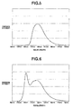
- the spectrum of illuminating light of the LED luminaire was measured by the spectrophotometer CL-500, with the result shown in FIG. 4 .
- an intensity S1 at wavelength 510 nm and an intensity S2 at wavelength 545 nm were measured, from which a ratio S1/S2 was calculated to be 0.668.
- Example 2 Seven white LED packages (XLamp LX-E Cool White by Cree Inc.) were arranged in an aluminum chassis and connected in series as in Example 1. A transparent matt acrylic plate of 2 mm thick as a protective cover was attached at a position spaced 25 mm apart from the emissive surface of the LED packages. An LED luminaire was fabricated as shown in FIG. 2 .
- the spectrum of illuminating light of the LED luminaire was measured as in Example 1.
- the intensity ratio S1/S2 was 0.657.
- a powder mixture 1,000 g, was obtained by mixing lutetium oxide (Lu 2 O 3 ) powder of 99.9% purity having an average particle size of 1.0 ⁇ m, aluminum oxide (Al 2 O 3 ) powder of 99.0% purity having an average particle size of 0.5 ⁇ m, and cerium oxide (CeO 2 ) powder of 99.9% purity having an average particle size of 0.2 ⁇ m in a molar ratio Lu:Al:Ce of 2.94:5.0:0.06.
- Barium fluoride, 200 g, as flux was added to the powder mixture, which was thoroughly mixed. The mixture was placed in an alumina crucible and heat treated in argon gas at 1,400°C for 10 hours.
- the fired product was disintegrated on a ball mill, washed with about 0.5 mol/L hydrochloric acid and then with deionized water. Subsequent solid/liquid separation and drying yielded Lu 3 Al 5 O 12 :Ce 3+ phosphor particles (Ce-activation rate relative to Lu is 2 mol%) having an average particle size of 20 ⁇ m.
- the phosphor particles were analyzed by XRD.
- the diffraction pattern of main phase of the phosphor particles is coincident with the diffraction peaks of lutetium aluminum garnet phase, demonstrating that Lu 3 Al 5 O 12 : Ce 3+ containing garnet phase as main phase is obtained.
- the luminescent spectrum of this phosphor in response to excitation light of wavelength 450 nm was measured by the spectrophotometer CL-500, with the result shown in FIG. 5 .
- This phosphor's emission peak near wavelength 510 nm was lower than at wavelength 545 nm.
- An LED package with a phosphor layer was manufactured as in Example 1 except that the phosphor used was the Lu 3 Al 5 O 12 : Ce 3+ phosphor particles (Ce-activation rate relative to Lu is 2 mol%) in Comparative Example 3. Using the packages, an LED luminaire was similarly fabricated.
- the spectrum of illuminating light of the LED luminaire was measured by the spectrophotometer CL-500, with the result shown in FIG. 6 .
- an intensity S1 at wavelength 510 nm and an intensity S2 at wavelength 545 nm were measured, from which a ratio S1/S2 was calculated to be 0.939.
- the LED luminaires of Examples 1 to 3 and Comparative Examples 1 to 3 were mounted at the top of posts along an asphalt roadway at a height of 3 m, and burned at night by applying a voltage of 24 V. The road surface and adjacent objects were visually observed. The LED luminaires of Examples were superior to the LED luminaires of Comparative Examples in that the space looked bright, shadows were less, and adjacent objects were clearly seen.
- the LED luminaires of Examples are excellent outdoor luminaires in that they produce effective lighting providing improved visual perception over a broader space including brightness of the overall space and brightness at the adjacent region.
- the LED luminaire of remote phosphor type in Example 3 provides surface emission, and due to an accordingly wide spread of illumination, non-glare lighting with less shadows is available. Since luminaires embodying the invention can produce lighting capable of complying with a change of visual sensitivity based on the Purkinje effect under scotopic and mesopic vision conditions, they are best suited for outdoor lighting.
Landscapes
- Chemical & Material Sciences (AREA)
- Engineering & Computer Science (AREA)
- Inorganic Chemistry (AREA)
- Materials Engineering (AREA)
- Organic Chemistry (AREA)
- Physics & Mathematics (AREA)
- Microelectronics & Electronic Packaging (AREA)
- Optics & Photonics (AREA)
- General Engineering & Computer Science (AREA)
- Luminescent Compositions (AREA)
- Led Device Packages (AREA)
- Non-Portable Lighting Devices Or Systems Thereof (AREA)
Abstract
Description
- This invention relates to an outdoor luminaire suitable for installation in those areas that are dim or dark at night or where least lamps are available, for example, pathways, roadways, plazas, residential areas, and tunnels.
- In modern cities, most areas are brightly illuminated even at night by many light sources including automobile headlights and store illuminations. On the other hand, most areas in suburbs and provincial districts are dark at night. Thus such areas as pathways, roadways, parks, and tunnels are provided with streetlights and outdoor luminaires for the safety and security purposes.
- However, when high-intensity luminaires are installed in suburbs and provincial districts and turned on at night to produce bright illumination, there arise problems including nuisance to the neighborhood, excessive power consumption, and high installation costs. It would be desirable to have outdoor luminaires which can attain the purposes of safety, security and crime prevention without excessive power consumption.
- When the light source for streetlights and outdoor luminaires is considered from the standpoints of maintenance and economy, LED lamps are of greater interest, because the LED lamps are advantageous in power consumption and lifetime over traditional incandescent lamps and fluorescent lamps. LED lamps come with a wide variation of light emission. Among them, blue LED lamps that produce light including a blue component may be used as the light source for outdoor luminaires, typically blue streetlights which are nowadays in widespread use. The power utility efficiency of LED lamps is very high. The power necessary for LED lamps to provide an equivalent illuminance is as low as 1/5 or less of the power consumed by incandescent lamps. LED lamps are generally believed to have a lifetime of several tens of thousands of hours, leading to savings of labor and cost for maintenance services. For these reasons, LED lamps are suited for use in streetlights and other outdoor luminaires which are intended for long-term continuous operation.
- White LED packages for general lighting application have a structure in which a phosphor is coated on a front surface of a blue LED chip having emission wavelength of 440 to 470 nm, or a phosphor layer is disposed immediately forward of a blue LED chip in the emission direction. With this structure, blue light is irradiated from the chip to the phosphor, which in turn, emits broad luminescent light having a peak wavelength around 550 nm, which is combined with blue light of unconverted wavelength to produce white light. White LED lamps for most luminaires utilize luminescent light having a peak wavelength of about 550 nm because human eyes have a high sensitivity to light of wavelength near 555 nm. In principle, light rich in this wavelength component provides highly effective lighting. However, it is known that under scotopic vision conditions at night streets or under mesopic vision conditions immediately after sunset, the peak wavelength of human visual sensitivity shifts from 555 nm to the shorter wavelength side as shown in
FIG. 7 . This is known as the Purkinje effect. - Under scotopic and mesopic vision conditions, among outdoor luminaires using white LEDs, those having an emission peak shifted to a wavelength shorter than 555 nm are preferred. For night lighting, luminaires having a high color temperature are under study (Non-Patent Document 1). These prior art night-lighting luminaires are not regarded as complying with a change of visual sensitivity based on the Purkinje effect because the light does not fully contain wavelength components of the highest visual sensitivity at the scotopic and mesopic vision levels.
-
Patent Document 1: JP-A 2008-135381 USP 8267541 ,EP 2088362 )Patent Document 2: JP-A 2009-151967 Patent Document 3: JP-A 2012-038504 Patent Document 4: JP-A 2012-009434 Non-Patent Document 1: Shirokura et al., "Influence on spatial brightness of spectral characteristics of streetlights", Journal of the Illuminating Engineering Institute of Japan, Vol. 96, No. 5, 259-271 (2012) - An object of the invention is to provide an outdoor luminaire which produces illumination affording good or improved brightness of lighting and visual perception and brightness over a broad range especially under scotopic and mesopic vision conditions such as often encountered in suburbs, provincial districts, rural districts and tunnels.
- Recently, street-lighting systems employ an increasing number of blue streetlights which are constructed by covering a fluorescent lamp with a blue cover so as to produce light of cold color. That is, the effect of cold color light like blue light, exerting certain tranquillity or sedation to human psychology, is utilized for the security light. Attempts are now made to design LED streetlights as blue streetlights. However, these streetlights are merely designed so as to increase the quantity of blue light, without taking into account the visual sensitivity under scotopic and mesopic vision conditions.
- The inventors looked to develop LED lighting that could mitigate a lowering of visual perception due to a change of visual sensitivity (or luminosity) wavelength under scotopic and mesopic vision conditions. Focusing on Lu3Al5O12: Ce3+ phosphor (LuAG phosphor) for use with blue LED as the light source/phosphor combination, the inventors made a study to improve the brightness perception and visual perception under scotopic and mesopic vision conditions of an LED lighting based on a combination of blue LED with LuAG phosphor.
- It is known that the LuAG phosphor is a yellowish green luminescent phosphor capable of emitting luminescent light having a peak wavelength of 520 to 560 nm in response to blue light. In the case of Y3Al5O12: Ce3+ (YAG phosphor) having a similar structure to the LuAG phosphor, part of Al is replaced by Ga in order to acquire emission of shorter wavelength, but at the sacrifice of quantum efficiency of the phosphor. It may be contemplated to replace part of Al by Ga in LuAG phosphor. However, such replacement is undesirable for lighting applications because a lowering of quantum efficiency of the phosphor is expected.
- Considering that the emission of LuAG phosphor has a spectrum of two overlapping emission profiles rather than a single emission profile, and the two emission profiles are assigned to 5d → 2F5/2 transition (emission peak on the shorter wavelength side) and 5d → 2F7/2 transition (emission peak on the longer wavelength side) of Ce3+ ion, the inventors presumed that if the emission profiles are controlled, the quantity of light emission of shorter wavelength might be increased and as a result, lighting suitable for use under scotopic and mesopic vision conditions might be available.
- The inventors have found that for LuAG phosphor, the probabilities of 5d → 2F5/2 transition (emission peak on the shorter wavelength side) and 5d → 2F7/2 transition (emission peak on the longer wavelength side) of Ce3+ ion are governed by the concentration of Ce; that by controlling the Ce concentration, the probability of 5d → 2F5/2 transition can be increased whereby the quantity of light emission near 510 nm having a high visual sensitivity under scotopic and mesopic vision conditions can be increased; and that by combining LuAG phosphor with blue LED, lighting suitable as outdoor lighting or night lighting is available.
- Attention is paid to Ce added as the activator to LuAG phosphor. When a percent activation rate of Ce relative to Lu is equal to or less than 1 mol%, the proportion of 5d → 2F5/2 transition becomes high, and so the proportion of light emission near 510 nm that is advantageous under scotopic and mesopic vision conditions is increased. When blue LED is combined with a LuAG phosphor having a Ce activation rate of up to 1 mol% relative to Lu, an outdoor lighting which is more useful under scotopic and mesopic vision conditions than the prior art is available.
- Accordingly, the invention provides an outdoor luminaire comprising a blue LED chip having a maximum peak at a wavelength of 420 to 480 nm and a phosphor layer disposed forward of the LED chip in its emission direction. The phosphor layer comprises a phosphor mixed and dispersed in a resin, and the phosphor has the compositional formula (1):
Lu3Al5O12 :Ce3+ (1)
and a Ce-activation rate relative to Lu of up to 1 mol%. - The resin may be a silicone resin or epoxy resin. Or, the resin may be at least one thermoplastic resin selected from among polyethylene, polypropylene, polyvinyl chloride, polyethylene terephthalate, polycarbonate, polystyrene, and ABS resins.
- The luminaire provides light having an intensity S1 at wavelength 510 nm and an intensity S2 at wavelength 545 nm, wherein the ratio of S1/S2 is preferably at least 0.95.
- We find that outdoor luminaires embodying the present proposals can produce illumination affording brighter lighting, higher visual perception and brightness over a broader range under scotopic and mesopic vision conditions.
-
-
FIG. 1 is a diagram showing the X-ray diffraction (XRD) profile of Lu3Al5O12 : Ce3+ phosphor in Example 1. -
FIG. 2 illustrates an LED luminaire manufactured in Examples and Comparative Examples, (A) being a partly cut-away plan view and (B) being a perspective view. -
FIG. 3 is a diagram showing the spectral profile of emission from an LED luminaire of Example 1. -
FIG. 4 is a diagram showing the spectral profile of emission from an LED luminaire of Comparative Example 1. -
FIG. 5 is a diagram showing the luminescent spectral profile of Lu3Al5O12 : Ce3+ phosphor in Comparative Example 3 in response to excitation light of wavelength 450 nm. -
FIG. 6 is a diagram showing the spectral profile of emission from an LED luminaire of Comparative Example 3. -
FIG. 7 is a diagram showing the emission spectrum (broken line) of a general white LED, and the peak wavelength (555 nm) in bright room and the peak wavelength (507 nm) in dark room of human eye sensitivity. - One aspect of the invention is an outdoor luminaire (lighting equipment, light fixture) comprising a blue LED chip having a maximum peak in the wavelength range of 420 to 480 nm. The blue LED chip may be a well-known blue LED package in which a blue LED chip, wirings and the like are sealed with an encapsulant. Any well-known or commercially available blue LED package may be used. Those blue LED chips having a maximum peak at a shorter or longer wavelength than the wavelength range defined above are undesirable because the excitation efficiency of phosphor is extremely reduced.
- The outdoor luminaire also comprises a phosphor layer which is disposed forward of the blue LED chip in its emission direction. The phosphor layer has a phosphor mixed and dispersed in a resin, the phosphor having the compositional formula (1):
Lu3Al5O12 :Ce3+ (1)
and a Ce-activation rate relative to Lu (i.e. a proportion of Ce, based on the sum of Lu and Ce) of up to 1 mol%, preferably at least 0.1 mol%. This phosphor is often referred to as "LuAG phosphor." Preferably the phosphor layer contains at least 0.1% by weight and up to 50% by weight of the LuAG phosphor of formula (1). - If the Ce-activation rate relative to Lu exceeds 1 mol%, a proportion of 5d → 2F7/2 transition becomes higher than a proportion of 5d → 2F5/2 transition, the peak position of emission spectrum shifts toward the longer wavelength side, and the emission wavelength largely deviates from the visual sensitivity under scotopic or mesopic vision, resulting in lighting with poor brightness under scotopic or mesopic vision. If the Ce-activation rate relative to Lu is less than 0.1 mol%, the phosphor itself may have a poor absorptivity with the risk that light near wavelength 510 nm, giving bright perception under scotopic or mesopic vision, may become short.
- The LuAG phosphor used herein is in particulate form. From the aspect of emission efficiency, the phosphor particles preferably have an average particle size of 1.5 to 50 microns (µm). If the average particle size is less than 1.5 µm, the emission efficiency of phosphor may lower, with a drop of lighting efficiency. If the average particle size exceeds 50 µm, this raises no problems with respect to lighting characteristics, but a larger amount of phosphor must be used to increase the number of particles, undesirably leading to an increased cost. The particle size of phosphor particles may be determined, for example, by dispersing phosphor particles in a gas or water stream and measuring their size by the laser diffraction scattering method.
- The LuAG phosphor used herein may be prepared by well-known methods. For example, lutetium oxide, cerium oxide and aluminum oxide in powder form are mixed in such amounts as to meet the desired composition. Barium fluoride is added thereto as a flux. The powder mixture is heated at a high temperature in air, an inert atmosphere (e.g., nitrogen) or reducing atmosphere (e.g. argon partly replaced by hydrogen) to form a complex oxide, which is disintegrated on a ball mill or the like to an appropriate size.
- In the phosphor layer, a phosphor other than the LuAG phosphor of formula (1) may be used, e.g. for the purposes of improving the tone and color rendering of outdoor lighting, as long as the present function is still provided.
- The resin of the phosphor layer may be either transparent or semi-transparent. For example, silicone resins and epoxy resins may be used. The phosphor layer may be formed by mixing and dispersing phosphor particles in an uncured resin composition, applying the resin composition to the surface of a blue LED chip or package, and curing the resin composition. Alternatively, a phosphor-loaded resin composition may be molded and cured to form a phosphor layer, which is disposed forward of a blue LED chip or package in its emission direction.
- In another preferred embodiment, the resin of the phosphor layer is a thermoplastic resin selected from among polyethylene, polypropylene, polyvinyl chloride, polyethylene terephthalate, polycarbonate, polystyrene, and ABS resin, alone or in admixture of two or more. Where a thermoplastic resin is used, a phosphor layer may be formed by milling phosphor particles with the thermoplastic resin to disperse the phosphor in the resin, and molding the resin, and the phosphor layer be disposed forward of a blue LED chip or package in its emission direction.
- For shaping of the phosphor layer, any well-known molding methods such as compression molding, extrusion molding and injection molding may be used. The material may be molded to any desired shape such as film or thin plate and to any desired size. The shape and size of the phosphor layer may be selected as appropriate depending on the application form of the phosphor layer. Typically the thickness of the phosphor layer is in a range of about 0.5 to 3 mm, though not particularly limited.
- Besides the phosphor and resin, additives may be used in the phosphor layer as long as the effect of the invention is still achieved. Suitable additives include auxiliary agents for improving weather resistance or preventing UV-induced degradation, such as radical scavengers and antioxidants, and light scattering agents for promoting light scattering, such as silica and talc. The content of such additive is typically up to 10% by weight, preferably 0.01 to 5% by weight of the phosphor layer.
- Preferably the outdoor luminaire takes the form of remote phosphor type in which the phosphor layer, especially a said phosphor layer based on a thermoplastic resin, is spaced apart from the blue LED package via a gas or vacuum layer. Since the luminaire of remote phosphor type has luminous intensity distribution characteristics different from general LED lamps, typically surface emission and a large radiation angle, it is particularly suited as the luminaire intended to provide illumination over a broad area.
- In a preferred embodiment, the outdoor luminaire produces light having an intensity S1 at wavelength 510 nm and an intensity S2 at wavelength 545 nm, wherein the ratio of S1/S2 is at least 0.95, more preferably at least 1. The luminaire is capable of complying with a change of visual sensitivity based on the Purkinje effect because the light is full of wavelengths giving a high visual sensitivity at scotopic and mesopic vision levels.
- The luminaire is suitable for installation in those areas with less brightness at night or where least light is available nearby, for example, pathways, roadways, plazas, residential areas, and tunnels. It is suitable for outdoor use, typically as streetlight. It may also be used indoors if the indoor area is in a similar dark environment, because it is suitable for use in scotopic and mesopic vision conditions. That is, the outdoor luminaire is one suitable for outdoor use, or is one actually outdoors.
- Examples and Comparative Examples are given below by way of illustration and not by way of limitation.
- A powder mixture, 1,000 g, was obtained by mixing lutetium oxide (Lu2O3) powder of 99.9% purity having an average particle size of 1.0 µm, aluminum oxide (Al2O3) powder of 99.0% purity having an average particle size of 0.5 µm, and cerium oxide (CeO2) powder of 99.9% purity having an average particle size of 0.2 µm in a molar ratio Lu:Al:Ce of 2.97:5.0:0.03. Barium fluoride, 200 g, as flux was added to the powder mixture, which was thoroughly mixed. The mixture was placed in an alumina crucible and heat treated in argon gas at 1,400°C for 10 hours. The fired product was disintegrated on a ball mill, washed with about 0.5 mol/L hydrochloric acid and then with deionized water. Subsequent solid/liquid separation and drying yielded Lu3Al5O12 : Ce3+ phosphor particles (Ce-activation rate relative to Lu is 1 mol%) having an average particle size of 20 µm.
- The result of XRD analysis of the phosphor particles is shown in
FIG. 1 . The diffraction pattern of main phase of the phosphor particles is coincident with the diffraction peaks of lutetium aluminum garnet phase, demonstrating that Lu3Al5O12: Ce3+ containing garnet phase as main phase is obtained. - The Lu3Al5O12: Ce3+ phosphor particles were dispersed in a transparent epoxy resin (SpeciFix-40 kit by Marumoto Struers K.K.) to form a slurry having a phosphor concentration of 20 wt%. The slurry was added dropwise to the emissive surface of a blue LED package (NS6b083T by Nichia Corp.) and cured at 50°C for 3 hours, completing an LED package having a phosphor layer containing phosphor particles mixed and dispersed in epoxy resin.
- Seven LED packages thus manufactured were arranged in a rectangular aluminum chassis of 39 mm wide, 220 mm long, and 30 mm deep (inside size) and connected in series. A transparent matt acrylic plate of 2 mm thick as a protective cover was attached at a position spaced 25 mm apart from the emissive surface of the LED packages. An LED luminaire was fabricated as shown in
FIG. 2 , whereinLED packages 1,aluminum chassis 2,protective cover 3,power supply terminals 4, andpower switch 5 are depicted. - The spectrum of illuminating light of the LED luminaire was measured by an illuminance spectrophotometer CL-500 (Konica Minolta, Inc.). The result is shown in
FIG. 3 . In the spectrum, an intensity S1 at wavelength 510 nm and an intensity S2 at wavelength 545 nm were measured, from which a ratio S1/S2 was calculated to be 1.076. - A powder mixture, 1,000 g, was obtained by mixing yttrium oxide (Y2O3) powder of 99.9% purity having an average particle size of 1.0 µm, aluminum oxide (Al2O3) powder of 99.0% purity having an average particle size of 0.5 µm, and cerium oxide (CeO2) powder of 99.9% purity having an average particle size of 0.2 µm in a molar ratio Y:Al:Ce of 2.94:5.0:0.06. Barium fluoride, 200 g, as flux was added to the powder mixture, which was thoroughly mixed. The mixture was placed in an alumina crucible and heat treated in argon gas at 1,400°C for 10 hours. The fired product was disintegrated on a ball mill, washed with about 0.5 mol/L hydrochloric acid and then with deionized water. Subsequent solid/liquid separation and drying yielded Y3Al5O12: Ce3+ phosphor particles having an average particle size of 20 µm.
- An LED package with a phosphor layer was manufactured as in Example 1 except that the Lu3Al5O12: Ce3+ phosphor particles in Example 1 and the Y3Al5O12: Ce3+ phosphor particles in Example 2 were dispersed in the transparent epoxy resin in an amount of 15 wt% and 5 wt%, respectively. Using the packages, an LED luminaire was similarly fabricated.
- The spectrum of illuminating light of the LED luminaire was measured as in Example 1. The intensity ratio S1/S2 was 0.983.
- Seven blue LED packages (XLamp LX-E Royal Blue by Cree Inc.) were arranged in an aluminum chassis and connected in series as in Example 1. The Lu3Al5O12: Ce3+ phosphor particles in Example 1 were kneaded in polycarbonate in a phosphor concentration of 5 wt%, and the resulting PC compound was molded into a PC plate of 2 mm thick. This PC plate as the phosphor layer was attached at a position spaced 25 mm apart from the emissive surface of the blue LED packages. An LED luminaire of remote phosphor type was fabricated as shown in
FIG. 2 , wherein theprotective cover 3 also serves as a phosphor layer. - The spectrum of illuminating light of the LED luminaire was measured as in Example 1. The intensity ratio S1/S2 was 1.067.
- An LED package with a phosphor layer was manufactured as in Example 1 except that the phosphor used was the Y3Al5O12: Ce3+ phosphor particles in Example 2 alone. Using the packages, an LED luminaire was similarly fabricated.
- The spectrum of illuminating light of the LED luminaire was measured by the spectrophotometer CL-500, with the result shown in
FIG. 4 . In the spectrum, an intensity S1 at wavelength 510 nm and an intensity S2 at wavelength 545 nm were measured, from which a ratio S1/S2 was calculated to be 0.668. - Seven white LED packages (XLamp LX-E Cool White by Cree Inc.) were arranged in an aluminum chassis and connected in series as in Example 1. A transparent matt acrylic plate of 2 mm thick as a protective cover was attached at a position spaced 25 mm apart from the emissive surface of the LED packages. An LED luminaire was fabricated as shown in
FIG. 2 . - The spectrum of illuminating light of the LED luminaire was measured as in Example 1. The intensity ratio S1/S2 was 0.657.
- A powder mixture, 1,000 g, was obtained by mixing lutetium oxide (Lu2O3) powder of 99.9% purity having an average particle size of 1.0 µm, aluminum oxide (Al2O3) powder of 99.0% purity having an average particle size of 0.5 µm, and cerium oxide (CeO2) powder of 99.9% purity having an average particle size of 0.2 µm in a molar ratio Lu:Al:Ce of 2.94:5.0:0.06. Barium fluoride, 200 g, as flux was added to the powder mixture, which was thoroughly mixed. The mixture was placed in an alumina crucible and heat treated in argon gas at 1,400°C for 10 hours. The fired product was disintegrated on a ball mill, washed with about 0.5 mol/L hydrochloric acid and then with deionized water. Subsequent solid/liquid separation and drying yielded Lu3Al5O12 :Ce3+ phosphor particles (Ce-activation rate relative to Lu is 2 mol%) having an average particle size of 20 µm.
- The phosphor particles were analyzed by XRD. The diffraction pattern of main phase of the phosphor particles is coincident with the diffraction peaks of lutetium aluminum garnet phase, demonstrating that Lu3Al5O12: Ce3+ containing garnet phase as main phase is obtained.
- The luminescent spectrum of this phosphor in response to excitation light of wavelength 450 nm was measured by the spectrophotometer CL-500, with the result shown in
FIG. 5 . This phosphor's emission peak near wavelength 510 nm was lower than at wavelength 545 nm. - An LED package with a phosphor layer was manufactured as in Example 1 except that the phosphor used was the Lu3Al5O12: Ce3+ phosphor particles (Ce-activation rate relative to Lu is 2 mol%) in Comparative Example 3. Using the packages, an LED luminaire was similarly fabricated.
- The spectrum of illuminating light of the LED luminaire was measured by the spectrophotometer CL-500, with the result shown in
FIG. 6 . In the spectrum, an intensity S1 at wavelength 510 nm and an intensity S2 at wavelength 545 nm were measured, from which a ratio S1/S2 was calculated to be 0.939. - The LED luminaires of Examples 1 to 3 and Comparative Examples 1 to 3 were mounted at the top of posts along an asphalt roadway at a height of 3 m, and burned at night by applying a voltage of 24 V. The road surface and adjacent objects were visually observed. The LED luminaires of Examples were superior to the LED luminaires of Comparative Examples in that the space looked bright, shadows were less, and adjacent objects were clearly seen.
- It has been demonstrated that the LED luminaires of Examples are excellent outdoor luminaires in that they produce effective lighting providing improved visual perception over a broader space including brightness of the overall space and brightness at the adjacent region. The LED luminaire of remote phosphor type in Example 3 provides surface emission, and due to an accordingly wide spread of illumination, non-glare lighting with less shadows is available. Since luminaires embodying the invention can produce lighting capable of complying with a change of visual sensitivity based on the Purkinje effect under scotopic and mesopic vision conditions, they are best suited for outdoor lighting.
- For the avoidance of doubt it is confirmed that in the general description above, in the usual way the proposal of general preferences and options in respect of different features of the luminaire and its manufacture and use constitutes the proposal of general combinations of those general preferences and options for the different features, insofar as they are combinable and compatible and are put forward in the same context.
- In respect of numerical ranges disclosed in the present description it will of course be understood that in the normal way the technical criterion for the upper limit is different from the technical criterion for the lower limit, i.e. the upper and lower limits are intrinsically distinct proposals.
Claims (7)
- An outdoor luminaire comprising a blue LED chip having a maximum peak at a wavelength of 420 to 480 nm and a phosphor layer disposed forwardly of the LED chip in its emission direction, said phosphor layer comprising a phosphor mixed and dispersed in a resin, the phosphor having the compositional formula (1):
Lu3Al5O12 :Ce3+ (1)
and a Ce-activation rate relative to Lu of not more than 1 mol%. - The luminaire of claim 1 wherein the resin is a silicone resin or epoxy resin.
- The luminaire of claim 1 wherein the resin is at least one thermoplastic resin selected from the group consisting of polyethylene, polypropylene, polyvinyl chloride, polyethylene terephthalate, polycarbonate, polystyrene, and ABS resin.
- The luminaire of any one of claims 1 to 3 which provides light having an intensity S1 at wavelength 510 nm and an intensity S2 at wavelength 545 nm, the ratio of S1/S2 being at least 0.95.
- The luminaire of any one of the preceding claims which is of remote phosphor type in which the phosphor layer is spaced apart from the blue LED chip.
- The luminaire of any one of the preceding claims in which said Ce-activation rate relative to Lu is at least 0.1 mol%.
- The luminaire of any one of the preceding claims which is a streetlight or light for a pathway, roadway, plaza, outdoor residential area or tunnel.
Applications Claiming Priority (1)
| Application Number | Priority Date | Filing Date | Title |
|---|---|---|---|
| JP2013132462A JP2015008061A (en) | 2013-06-25 | 2013-06-25 | Outdoor lighting |
Publications (1)
| Publication Number | Publication Date |
|---|---|
| EP2824160A1 true EP2824160A1 (en) | 2015-01-14 |
Family
ID=50943229
Family Applications (1)
| Application Number | Title | Priority Date | Filing Date |
|---|---|---|---|
| EP14173102.6A Withdrawn EP2824160A1 (en) | 2013-06-25 | 2014-06-19 | Outdoor luminaire |
Country Status (6)
| Country | Link |
|---|---|
| US (1) | US9978913B2 (en) |
| EP (1) | EP2824160A1 (en) |
| JP (1) | JP2015008061A (en) |
| KR (1) | KR20150000841A (en) |
| CN (1) | CN104253196A (en) |
| TW (1) | TW201525345A (en) |
Families Citing this family (4)
| Publication number | Priority date | Publication date | Assignee | Title |
|---|---|---|---|---|
| JP2017017059A (en) | 2015-06-26 | 2017-01-19 | パナソニックIpマネジメント株式会社 | Illumination light source and illumination device |
| JP2017140240A (en) * | 2016-02-10 | 2017-08-17 | パナソニックIpマネジメント株式会社 | Light emitting device |
| US11142691B2 (en) * | 2017-10-31 | 2021-10-12 | Nichia Corporation | Rare earth aluminate fluorescent material, and method for producing the same |
| CN113272260A (en) * | 2019-03-08 | 2021-08-17 | 日本电气硝子株式会社 | Wavelength conversion member and light emitting apparatus |
Citations (9)
| Publication number | Priority date | Publication date | Assignee | Title |
|---|---|---|---|---|
| US20040256974A1 (en) * | 2003-03-17 | 2004-12-23 | Lumileds Lighting, U.S., Llc | Phosphor converted light emitting device |
| JP2008135381A (en) | 2006-10-25 | 2008-06-12 | Osaka Prefecture | Outdoor lighting apparatus and lighting method |
| JP2009151967A (en) | 2007-12-19 | 2009-07-09 | Hiroshima Kasei Ltd | LED lamp |
| EP2088362A1 (en) | 2006-10-25 | 2009-08-12 | Osaka Prefectural Government | Outdoor illuminating device and illuminating method |
| JP2012009434A (en) | 2010-05-27 | 2012-01-12 | Tottori Denshi Kk | Lighting system |
| JP2012038504A (en) | 2010-08-05 | 2012-02-23 | Hiroshima Kasei Ltd | Outdoor lighting fixture |
| US20120087108A1 (en) * | 2010-10-12 | 2012-04-12 | Au Optronics Corporation | LED Apparatus |
| EP2474590A2 (en) * | 2011-01-06 | 2012-07-11 | Shin-Etsu Chemical Co., Ltd. | Phosphor particles and making method |
| WO2012106282A1 (en) * | 2011-02-04 | 2012-08-09 | Osram Sylvania Inc. | Wavelength converter for an led, method of making, and led containing same |
Family Cites Families (15)
| Publication number | Priority date | Publication date | Assignee | Title |
|---|---|---|---|---|
| JP4406490B2 (en) | 2000-03-14 | 2010-01-27 | 株式会社朝日ラバー | Light emitting diode |
| EP1566426B1 (en) | 2004-02-23 | 2015-12-02 | Philips Lumileds Lighting Company LLC | Phosphor converted light emitting device |
| JP2005353649A (en) * | 2004-06-08 | 2005-12-22 | Matsushita Electric Ind Co Ltd | LED light source and manufacturing method thereof |
| JP5036222B2 (en) * | 2006-06-01 | 2012-09-26 | 京セラ株式会社 | Light emitting device |
| US8529791B2 (en) * | 2006-10-20 | 2013-09-10 | Intematix Corporation | Green-emitting, garnet-based phosphors in general and backlighting applications |
| JP5327601B2 (en) * | 2008-12-12 | 2013-10-30 | 東芝ライテック株式会社 | Light emitting module and lighting device |
| JP5200067B2 (en) * | 2009-07-13 | 2013-05-15 | 三菱電機株式会社 | Light emitting device |
| CN102135239B (en) * | 2010-01-21 | 2013-01-23 | 财团法人工业技术研究院 | Illumination device and its optical element module |
| JP5323131B2 (en) * | 2010-06-09 | 2013-10-23 | 信越化学工業株式会社 | Fluorescent particles, light-emitting diodes, illumination device using them, and backlight device for liquid crystal panel |
| JP2012049333A (en) * | 2010-08-26 | 2012-03-08 | Panasonic Electric Works Co Ltd | Light emitting device |
| CN102315371A (en) | 2010-07-05 | 2012-01-11 | 松下电工株式会社 | Light-emitting device |
| US9133392B2 (en) * | 2010-07-22 | 2015-09-15 | Osram Opto Semiconductors Gmbh | Garnet material, method for its manufacturing and radiation-emitting component comprising the garnet material |
| JP5676653B2 (en) * | 2011-01-18 | 2015-02-25 | シャープ株式会社 | Semiconductor light emitting device |
| JP2012227017A (en) * | 2011-04-20 | 2012-11-15 | Panasonic Corp | Lighting fixture |
| WO2013074158A1 (en) * | 2011-11-16 | 2013-05-23 | Intematix Corporation | Green and yellow aluminate phosphors |
-
2013
- 2013-06-25 JP JP2013132462A patent/JP2015008061A/en active Pending
-
2014
- 2014-06-19 EP EP14173102.6A patent/EP2824160A1/en not_active Withdrawn
- 2014-06-20 US US14/309,993 patent/US9978913B2/en not_active Expired - Fee Related
- 2014-06-23 TW TW103121547A patent/TW201525345A/en unknown
- 2014-06-24 KR KR20140077521A patent/KR20150000841A/en not_active Ceased
- 2014-06-25 CN CN201410290163.8A patent/CN104253196A/en active Pending
Patent Citations (10)
| Publication number | Priority date | Publication date | Assignee | Title |
|---|---|---|---|---|
| US20040256974A1 (en) * | 2003-03-17 | 2004-12-23 | Lumileds Lighting, U.S., Llc | Phosphor converted light emitting device |
| JP2008135381A (en) | 2006-10-25 | 2008-06-12 | Osaka Prefecture | Outdoor lighting apparatus and lighting method |
| EP2088362A1 (en) | 2006-10-25 | 2009-08-12 | Osaka Prefectural Government | Outdoor illuminating device and illuminating method |
| US8267541B2 (en) | 2006-10-25 | 2012-09-18 | Osaka Prefectural Government | Outdoor illuminating device and illuminating method |
| JP2009151967A (en) | 2007-12-19 | 2009-07-09 | Hiroshima Kasei Ltd | LED lamp |
| JP2012009434A (en) | 2010-05-27 | 2012-01-12 | Tottori Denshi Kk | Lighting system |
| JP2012038504A (en) | 2010-08-05 | 2012-02-23 | Hiroshima Kasei Ltd | Outdoor lighting fixture |
| US20120087108A1 (en) * | 2010-10-12 | 2012-04-12 | Au Optronics Corporation | LED Apparatus |
| EP2474590A2 (en) * | 2011-01-06 | 2012-07-11 | Shin-Etsu Chemical Co., Ltd. | Phosphor particles and making method |
| WO2012106282A1 (en) * | 2011-02-04 | 2012-08-09 | Osram Sylvania Inc. | Wavelength converter for an led, method of making, and led containing same |
Non-Patent Citations (1)
| Title |
|---|
| SHIROKURA ET AL.: "Influence on spatial brightness of spectral characteristics of streetlights", JOURNAL OF THE ILLUMINATING ENGINEERING INSTITUTE OF JAPAN, vol. 96, no. 5, 2012, pages 259 - 271 |
Also Published As
| Publication number | Publication date |
|---|---|
| CN104253196A (en) | 2014-12-31 |
| KR20150000841A (en) | 2015-01-05 |
| TW201525345A (en) | 2015-07-01 |
| US20140376229A1 (en) | 2014-12-25 |
| JP2015008061A (en) | 2015-01-15 |
| US9978913B2 (en) | 2018-05-22 |
Similar Documents
| Publication | Publication Date | Title |
|---|---|---|
| EP3115677B1 (en) | Lighting apparatus | |
| CN101688644B (en) | Lighting device and lighting method | |
| CN101611259B (en) | Lighting device and lighting method | |
| CN101720402B (en) | Lighting device and lighting method | |
| CN101617411B (en) | Lighting device and lighting method | |
| CN101755164B (en) | Lighting device and lighting method | |
| CN101617405B (en) | Lighting device and lighting method | |
| CN101711325B (en) | Lighting device and lighting method | |
| JP5244090B2 (en) | Lighting device and lighting method | |
| US11248750B2 (en) | LED lighting units, materials, and optical components for white light illumination | |
| CN101449100B (en) | Lighting device | |
| CN101554089A (en) | Lighting device and lighting method | |
| US9978913B2 (en) | Outdoor luminaire | |
| JP2024096316A (en) | Light-emitting devices, lighting fixtures and street lights | |
| CN110081346B (en) | Tunnel illuminating lamp capable of improving vision distance and tunnel illuminating system | |
| US20170336040A1 (en) | Led light source for vehicle-mounted headlight | |
| CN102037785A (en) | Lighting device and lighting method | |
| CN201739794U (en) | Integrated package high-power LED illuminating lamp | |
| CN210179499U (en) | Bird-friendly solar gear-shifting LED street lamp |
Legal Events
| Date | Code | Title | Description |
|---|---|---|---|
| 17P | Request for examination filed |
Effective date: 20140619 |
|
| AK | Designated contracting states |
Kind code of ref document: A1 Designated state(s): AL AT BE BG CH CY CZ DE DK EE ES FI FR GB GR HR HU IE IS IT LI LT LU LV MC MK MT NL NO PL PT RO RS SE SI SK SM TR |
|
| AX | Request for extension of the european patent |
Extension state: BA ME |
|
| PUAI | Public reference made under article 153(3) epc to a published international application that has entered the european phase |
Free format text: ORIGINAL CODE: 0009012 |
|
| R17P | Request for examination filed (corrected) |
Effective date: 20150626 |
|
| RBV | Designated contracting states (corrected) |
Designated state(s): AL AT BE BG CH CY CZ DE DK EE ES FI FR GB GR HR HU IE IS IT LI LT LU LV MC MK MT NL NO PL PT RO RS SE SI SK SM TR |
|
| 17Q | First examination report despatched |
Effective date: 20161223 |
|
| STAA | Information on the status of an ep patent application or granted ep patent |
Free format text: STATUS: THE APPLICATION IS DEEMED TO BE WITHDRAWN |
|
| 18D | Application deemed to be withdrawn |
Effective date: 20170704 |