EP2823791A1 - Multi-articulated link knee joint - Google Patents
Multi-articulated link knee joint Download PDFInfo
- Publication number
- EP2823791A1 EP2823791A1 EP12870368.3A EP12870368A EP2823791A1 EP 2823791 A1 EP2823791 A1 EP 2823791A1 EP 12870368 A EP12870368 A EP 12870368A EP 2823791 A1 EP2823791 A1 EP 2823791A1
- Authority
- EP
- European Patent Office
- Prior art keywords
- magnet
- knee
- piston rod
- knee joint
- link
- Prior art date
- Legal status (The legal status is an assumption and is not a legal conclusion. Google has not performed a legal analysis and makes no representation as to the accuracy of the status listed.)
- Granted
Links
Images




Classifications
-
- A—HUMAN NECESSITIES
- A61—MEDICAL OR VETERINARY SCIENCE; HYGIENE
- A61F—FILTERS IMPLANTABLE INTO BLOOD VESSELS; PROSTHESES; DEVICES PROVIDING PATENCY TO, OR PREVENTING COLLAPSING OF, TUBULAR STRUCTURES OF THE BODY, e.g. STENTS; ORTHOPAEDIC, NURSING OR CONTRACEPTIVE DEVICES; FOMENTATION; TREATMENT OR PROTECTION OF EYES OR EARS; BANDAGES, DRESSINGS OR ABSORBENT PADS; FIRST-AID KITS
- A61F2/00—Filters implantable into blood vessels; Prostheses, i.e. artificial substitutes or replacements for parts of the body; Appliances for connecting them with the body; Devices providing patency to, or preventing collapsing of, tubular structures of the body, e.g. stents
- A61F2/50—Prostheses not implantable in the body
- A61F2/60—Artificial legs or feet or parts thereof
- A61F2/64—Knee joints
- A61F2/642—Polycentric joints, without longitudinal rotation
- A61F2/644—Polycentric joints, without longitudinal rotation of the single-bar or multi-bar linkage type
-
- A—HUMAN NECESSITIES
- A61—MEDICAL OR VETERINARY SCIENCE; HYGIENE
- A61F—FILTERS IMPLANTABLE INTO BLOOD VESSELS; PROSTHESES; DEVICES PROVIDING PATENCY TO, OR PREVENTING COLLAPSING OF, TUBULAR STRUCTURES OF THE BODY, e.g. STENTS; ORTHOPAEDIC, NURSING OR CONTRACEPTIVE DEVICES; FOMENTATION; TREATMENT OR PROTECTION OF EYES OR EARS; BANDAGES, DRESSINGS OR ABSORBENT PADS; FIRST-AID KITS
- A61F2/00—Filters implantable into blood vessels; Prostheses, i.e. artificial substitutes or replacements for parts of the body; Appliances for connecting them with the body; Devices providing patency to, or preventing collapsing of, tubular structures of the body, e.g. stents
- A61F2/50—Prostheses not implantable in the body
- A61F2/76—Means for assembling, fitting or testing prostheses, e.g. for measuring or balancing, e.g. alignment means
-
- A—HUMAN NECESSITIES
- A61—MEDICAL OR VETERINARY SCIENCE; HYGIENE
- A61F—FILTERS IMPLANTABLE INTO BLOOD VESSELS; PROSTHESES; DEVICES PROVIDING PATENCY TO, OR PREVENTING COLLAPSING OF, TUBULAR STRUCTURES OF THE BODY, e.g. STENTS; ORTHOPAEDIC, NURSING OR CONTRACEPTIVE DEVICES; FOMENTATION; TREATMENT OR PROTECTION OF EYES OR EARS; BANDAGES, DRESSINGS OR ABSORBENT PADS; FIRST-AID KITS
- A61F2/00—Filters implantable into blood vessels; Prostheses, i.e. artificial substitutes or replacements for parts of the body; Appliances for connecting them with the body; Devices providing patency to, or preventing collapsing of, tubular structures of the body, e.g. stents
- A61F2/50—Prostheses not implantable in the body
- A61F2002/5003—Prostheses not implantable in the body having damping means, e.g. shock absorbers
- A61F2002/5006—Dampers, e.g. hydraulic damper
-
- A—HUMAN NECESSITIES
- A61—MEDICAL OR VETERINARY SCIENCE; HYGIENE
- A61F—FILTERS IMPLANTABLE INTO BLOOD VESSELS; PROSTHESES; DEVICES PROVIDING PATENCY TO, OR PREVENTING COLLAPSING OF, TUBULAR STRUCTURES OF THE BODY, e.g. STENTS; ORTHOPAEDIC, NURSING OR CONTRACEPTIVE DEVICES; FOMENTATION; TREATMENT OR PROTECTION OF EYES OR EARS; BANDAGES, DRESSINGS OR ABSORBENT PADS; FIRST-AID KITS
- A61F2/00—Filters implantable into blood vessels; Prostheses, i.e. artificial substitutes or replacements for parts of the body; Appliances for connecting them with the body; Devices providing patency to, or preventing collapsing of, tubular structures of the body, e.g. stents
- A61F2/50—Prostheses not implantable in the body
- A61F2002/5081—Additional features
- A61F2002/5084—Additional features telescopic
-
- A—HUMAN NECESSITIES
- A61—MEDICAL OR VETERINARY SCIENCE; HYGIENE
- A61F—FILTERS IMPLANTABLE INTO BLOOD VESSELS; PROSTHESES; DEVICES PROVIDING PATENCY TO, OR PREVENTING COLLAPSING OF, TUBULAR STRUCTURES OF THE BODY, e.g. STENTS; ORTHOPAEDIC, NURSING OR CONTRACEPTIVE DEVICES; FOMENTATION; TREATMENT OR PROTECTION OF EYES OR EARS; BANDAGES, DRESSINGS OR ABSORBENT PADS; FIRST-AID KITS
- A61F2/00—Filters implantable into blood vessels; Prostheses, i.e. artificial substitutes or replacements for parts of the body; Appliances for connecting them with the body; Devices providing patency to, or preventing collapsing of, tubular structures of the body, e.g. stents
- A61F2/50—Prostheses not implantable in the body
- A61F2/68—Operating or control means
- A61F2002/6863—Operating or control means magnetic
-
- A—HUMAN NECESSITIES
- A61—MEDICAL OR VETERINARY SCIENCE; HYGIENE
- A61F—FILTERS IMPLANTABLE INTO BLOOD VESSELS; PROSTHESES; DEVICES PROVIDING PATENCY TO, OR PREVENTING COLLAPSING OF, TUBULAR STRUCTURES OF THE BODY, e.g. STENTS; ORTHOPAEDIC, NURSING OR CONTRACEPTIVE DEVICES; FOMENTATION; TREATMENT OR PROTECTION OF EYES OR EARS; BANDAGES, DRESSINGS OR ABSORBENT PADS; FIRST-AID KITS
- A61F2/00—Filters implantable into blood vessels; Prostheses, i.e. artificial substitutes or replacements for parts of the body; Appliances for connecting them with the body; Devices providing patency to, or preventing collapsing of, tubular structures of the body, e.g. stents
- A61F2/50—Prostheses not implantable in the body
- A61F2/68—Operating or control means
- A61F2/70—Operating or control means electrical
- A61F2002/704—Operating or control means electrical computer-controlled, e.g. robotic control
-
- A—HUMAN NECESSITIES
- A61—MEDICAL OR VETERINARY SCIENCE; HYGIENE
- A61F—FILTERS IMPLANTABLE INTO BLOOD VESSELS; PROSTHESES; DEVICES PROVIDING PATENCY TO, OR PREVENTING COLLAPSING OF, TUBULAR STRUCTURES OF THE BODY, e.g. STENTS; ORTHOPAEDIC, NURSING OR CONTRACEPTIVE DEVICES; FOMENTATION; TREATMENT OR PROTECTION OF EYES OR EARS; BANDAGES, DRESSINGS OR ABSORBENT PADS; FIRST-AID KITS
- A61F2/00—Filters implantable into blood vessels; Prostheses, i.e. artificial substitutes or replacements for parts of the body; Appliances for connecting them with the body; Devices providing patency to, or preventing collapsing of, tubular structures of the body, e.g. stents
- A61F2/50—Prostheses not implantable in the body
- A61F2/76—Means for assembling, fitting or testing prostheses, e.g. for measuring or balancing, e.g. alignment means
- A61F2002/7615—Measuring means
- A61F2002/762—Measuring means for measuring dimensions, e.g. a distance
-
- A—HUMAN NECESSITIES
- A61—MEDICAL OR VETERINARY SCIENCE; HYGIENE
- A61F—FILTERS IMPLANTABLE INTO BLOOD VESSELS; PROSTHESES; DEVICES PROVIDING PATENCY TO, OR PREVENTING COLLAPSING OF, TUBULAR STRUCTURES OF THE BODY, e.g. STENTS; ORTHOPAEDIC, NURSING OR CONTRACEPTIVE DEVICES; FOMENTATION; TREATMENT OR PROTECTION OF EYES OR EARS; BANDAGES, DRESSINGS OR ABSORBENT PADS; FIRST-AID KITS
- A61F2/00—Filters implantable into blood vessels; Prostheses, i.e. artificial substitutes or replacements for parts of the body; Appliances for connecting them with the body; Devices providing patency to, or preventing collapsing of, tubular structures of the body, e.g. stents
- A61F2/50—Prostheses not implantable in the body
- A61F2/76—Means for assembling, fitting or testing prostheses, e.g. for measuring or balancing, e.g. alignment means
- A61F2002/7615—Measuring means
- A61F2002/7625—Measuring means for measuring angular position
-
- A—HUMAN NECESSITIES
- A61—MEDICAL OR VETERINARY SCIENCE; HYGIENE
- A61F—FILTERS IMPLANTABLE INTO BLOOD VESSELS; PROSTHESES; DEVICES PROVIDING PATENCY TO, OR PREVENTING COLLAPSING OF, TUBULAR STRUCTURES OF THE BODY, e.g. STENTS; ORTHOPAEDIC, NURSING OR CONTRACEPTIVE DEVICES; FOMENTATION; TREATMENT OR PROTECTION OF EYES OR EARS; BANDAGES, DRESSINGS OR ABSORBENT PADS; FIRST-AID KITS
- A61F2/00—Filters implantable into blood vessels; Prostheses, i.e. artificial substitutes or replacements for parts of the body; Appliances for connecting them with the body; Devices providing patency to, or preventing collapsing of, tubular structures of the body, e.g. stents
- A61F2/50—Prostheses not implantable in the body
- A61F2/76—Means for assembling, fitting or testing prostheses, e.g. for measuring or balancing, e.g. alignment means
- A61F2002/7615—Measuring means
- A61F2002/7665—Measuring means for measuring temperatures
Definitions
- the present invention relates to a multi-articulated link knee joint that is a joint including a knee section of a multi-articulated link mechanism.
- a single-axis knee joint that is a joint including a knee section with a single axis
- a multi-articulated link knee joint that is a joint including a knee section of a multi-articulated link mechanism.
- a multi-articulated link knee joint includes various advantages as compared with a single-axis joint.
- the position of the instantaneous center of rotation of a knee section is in the position closer to a hip joint as compared with a single-axis knee joint, and therefore, the multi-articulated link knee joint includes the advantage of hardly dropping off at an early stage of standing as compared with the single-axis joint.
- the multi-articulated link knee joint includes the advantage that the toe is hardly caught by the ground.
- the multi-articulated link knee joint can obtain beautiful gait without a vertical movement, as compared with a single-axis knee joint.
- a multi-articulated link knee joint includes the advantage that the knee cap hardly protrudes at the time of being in a sitting position as compared with a single-axis knee joint.
- a multi-articulated link knee joint includes the advantage that even when a user of an artificial leg with knee disarticulation or a long stump uses the multi-articulated link knee joint, the thigh length thereof can be made closer to the thigh length of a well leg, as compared with a single-axis knee joint.
- a knee joint that includes a knee section of a multi-articulated link mechanism, an air cylinder that assists an action of the knee section, and a computer that controls an operation of the air cylinder (See Patent Literatures 1 and 2, for example.).
- the computers in the conventional multi-articulated link knee joints are considered to be more preferable if the computers can control the operation of the air cylinders in accordance with the bending angles of the knee sections.
- the knee section is not a single-axis knee section in which the position of the center of rotation is constant irrespective of the bending angle, but is the knee section of the multi-articulated link mechanism in which the position of the center of rotation changes in accordance with a change in the bending angle as shown in Figure 8 , and the action range of the knee section is large, the bending angle of the knee section cannot be detected by only detecting the angle that is formed by specific two links connected to each other among the links that configure the knee section.
- Figure 8 is an explanatory view of the background art, and is a view showing the change of the position of the center of rotation of a knee section 92 according to the bending angle of the knee section 92 of a multi-articulated link knee joint 90.
- the multi-articulated link knee joint 90 includes a frame 91 and a knee section 92 of a multi-articulated link mechanism.
- the knee section 92 includes an upper link 93 including a thigh connection portion 93a for a thigh portion side socket of a user of the artificial leg to be connected, a lower link 94 that is fixed to the frame 91, a front link 95 to which the upper link 93 and the lower link 94 are connected, and a rear link 96 to which the upper link 93 and the lower link 94 are connected.
- the lower link 94 includes a shaft 94a that rotatably supports the rear link 96.
- the front link 95 includes a shaft 95a that rotatably supports the upper link 93, and a shaft 95b that is rotatably supported by the lower link 94.
- the rear link 96 includes a shaft 96a that rotatably supports the upper link 93.
- a curved line 97 with a plurality of solid-white circles is a line expressing the trajectory of the position of the center of rotation of the knee section 92 according to the change of the bending angle of the knee section 92.
- the solid-white circles on the curved line 97 represent the positions of the centers of rotation of the knee section 92 in the case in which the angles described in the vicinities thereof being the bending angles of the knee section 92.
- the state shown in Figure 8 , of the multi-articulated link knee joint 90 is the state of the case of the bending angle of the knee section 92 being 0°.
- the relative positional relation of the respective links changes significantly with the change of the bending angle of the knee section.
- the present invention has an object to provide a multi-articulated link knee joint capable of detecting a bending angle of a knee section without causing problems of an installation space and wiring of a sensor.
- a multi-articulated link knee joint of the present invention includes a knee section of a multi-articulated link mechanism, a cylinder that restrains or assists an action of the knee section, and extension and contraction amount detecting unit that detects an extension and contraction amount of the cylinder, and angle acquiring unit that acquires a bending angle of the knee section by converting the extension and contraction amount that is detected by the extension and contraction amount detecting unit.
- the multi-articulated link knee joint of the present invention can detect the bending (or extending) angle of the knee section by converting the extension and contraction amount of the cylinder that restrains or assists the action of the knee section. Namely, the multi-articulated link knee joint of the present invention can detect the bending angle of the knee section without causing the problems of the installation space and wiring of the sensor.
- the extension and contraction amount detecting unit of the multi-articulated link knee joint of the present invention includes a magnet and a magnetic sensor that detects a position of the magnet, one of the magnet and the magnetic sensor is accommodated in a piston rod of the cylinder, the other one of the magnet and the magnetic sensor is fixed to a cylinder tube of the cylinder, and as the extension and contraction amount, the extension and contraction amount detecting unit may detect a position of the piston rod with respect to the cylinder tube by the magnet and the magnetic sensor.
- the multi-articulated link knee joint of the present invention detects the position of the piston rod with respect to the cylinder tube as the extension and contraction amount of the cylinder by the magnetic method, and therefore, as compared with the configuration that detects the position of the piston rod with respect to the cylinder tube by a contact or optical method, the possibility of reduction in detection precision by contamination caused by being used can be reduced.
- the magnet of the multi-articulated link knee joint of the present invention is accommodated in the piston rod, and the magnetic sensor may be fixed to the cylinder tube.
- the magnet is accommodated in the piston rod, and therefore, the magnet can be prevented from being broken by an external force. Further, in the multi-articulated link knee joint of the present invention, arrangement of wiring of the magnetic sensor can be facilitated, as compared with the configuration in which the magnetic sensor is accommodated in the piston rod.
- the magnet of the multi-articulated link knee joint of the present invention extends in the extending direction of the piston rod to be longer than a stroke of the cylinder corresponding to an action range of the knee section, a magnetizing direction is the extending direction of the piston rod, and the magnetic sensor may detect a position of the magnet according to a magnitude of a magnetic field generated by the magnet.
- the number of magnets needed to detect the position of the piston rod with respect to the cylinder tube of the cylinder can be made one.
- the magnet of the multi-articulated link knee joint of the present invention extends in an extending direction of the piston rod to be longer than a stroke of the cylinder corresponding to an action range of the knee section, a magnetizing direction is the extending direction of the piston rod, the magnetic sensor detects a position of the magnet according to a magnitude of a magnetic field generated by the magnet, and in the magnet, a section orthogonal to an extending direction may be circular.
- the magnet does not have to be fixed so as not to rotate in the piston rod, simplification of the configuration can be achieved, and reduction in detection precision of the position of the piston rod with respect to the cylinder tube can be restrained.
- the multi-articulated link knee joint of the present invention can detect the bending angle of the knee section without causing problems of the installation space and wiring of the sensor.
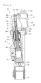
- Figure 1 is a side sectional view of a four-link knee joint 10 according to the present embodiment in a case in which a bending angle of a knee section 30 is 0°.
- Figure 2 is a side sectional view of the four-link knee joint 10 in a case in which the bending angle of the knee section 30 is 90°.
- Figure 3 is a block diagram of the four-link knee joint 10.
- the four-link knee joint 10 includes a frame 20, the knee section 30 of a four-link mechanism, a fluid cylinder 40 that is cylinder using oil as a working fluid, and restricts an action of the knee section 30 by generating a fluid resistance, a drive device 50 for changing a property of the fluid cylinder 40, a position detecting device 60 as extension and contraction amount detecting unit that detects a position of a piston rod 42 with respect to a cylinder tube 41 of the fluid cylinder 40 as an extension and contraction amount of the fluid cylinder 40, a signal processing circuit 70 that processes a signal that is outputted from the position detecting device 60, a computer 80 that controls the property (the magnitude of the fluid resistance to be generated) of the fluid cylinder 40 by controlling an operation of the drive device 50, and a battery not illustrated that supplies power to various components such as the drive device 50, the signal processing circuit 70 and the computer 80.
- drive device 50 the signal processing circuit 70, the computer 80 and the battery are not illustrated in Figure 1 and Figure 2 , but are actually mounted on the frame 20 or the fluid cylinder 40.
- the knee section 30 is fixed to the frame 20.
- the frame 20 includes a leg connection portion 21 for a pipe of a leg portion not illustrated to be connected, in an end at an opposite side from a side where the knee section 30 is provided. Further, the frame 20 includes a shaft 22 that rotatably supports the cylinder tube 41. Note that the four-link knee joint 10 forms an artificial leg by being combined with the leg portion.
- the knee section 30 includes an upper link 31 including a thigh connection portion 31a for a thigh portion side socket of a user of the artificial leg to be connected, a lower link 32 that is fixed to the frame 20, a front link 33 to which the upper link 31 and the lower link 32 are connected, and a rear link 34 to which the upper link 31 and the lower link 32 are connected.
- the upper link 31 includes a shaft 31b that rotatably supports the piston rod 42.
- the lower link 32 includes a shaft 32a that rotatably supports the rear link 34.
- the front link 33 includes a shaft 33a that rotatably supports the upper link 31, and a shaft 33b that is rotatably supported by the lower link 32.
- the rear link 34 includes a shaft 34a that rotatably supports the upper link 31.
- the shaft 31b is disposed at an upper side from a line connecting the shaft 33a and the shaft 34a. Further, the shaft 22 that rotatably supports the cylinder tube 41 is disposed at a lower side from the frame 20. Accordingly, the fluid cylinder 40 is accommodated so as to be able to extend and contract and swing in an inner side of the frame 20.
- the fluid cylinder 40 includes the cylinder tube 41, the piston rod 42 that is movable with respect to the cylinder tube 41, and a piston 43 that is movably accommodated in the cylinder tube 41, and has the piston rod 42 fixed thereto.
- the piston rod 42 is formed of a non-magnetic material.
- the piston rod 42 includes a rod main body 42a in which a space for accommodating a magnet 61 that will be described later is formed, a rod end 42b that is fixed to the rod main body 42a, and spacers 42c and 42d that are adjusted to have predetermined lengths to sandwich and fix the magnet 61 inside the piston rod 42.
- a female screw is formed at the rod main body 42a.
- a male screw that is combined with the female screw of the rod main body 42a is formed on the rod end 42b.
- the position detecting device 60 includes the magnet 61 that is accommodated in the piston rod 42, and a magnetic sensor 62 that is fixed to the cylinder tube 41 and detects a position of the magnet 61.
- the magnet 61 is an alnico magnet, for example.
- the magnetic sensor 62 is a sensor that detects a position of the magnet 61 in accordance with the magnitude of a magnetic field that is generated by the magnet 61, and is a Hall element, for example.
- the spacer 42c, the magnet 61, and the spacer 42d are accommodated in the rod main body 42a in this sequence, and thereafter, the male screw of the rod end 42b and the female screw of the rod main body 42a are fastened, whereby the magnet 61 is fixed to a predetermined position in an inside thereof.
- the computer 80 is an MCU (Micro Control Unit), for example.
- the computer 80 is configured to acquire the bending angle of the knee section 30, that is, a bending (or extending) angle of the four-link knee joint 10 with respect to the thigh portion of the user of the artificial leg that is connected to the thigh connection portion 31a by converting the position detected by the magnetic sensor 62, and configures angle acquiring unit of the present invention.
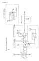
- Figure 4 is a block diagram of the signal processing circuit 70.
- the signal processing circuit 70 includes a reference power supply section 71 including a voltage reference 71a that generates Vref that is a reference voltage with little temperature change that is inputted into a magnetic sensor 62 from Vcc that is a power supply voltage from a battery not illustrated, a signal adjusting section 72 that adjusts VH that is an output voltage of the magnetic sensor 62, a temperature correcting section 73 that performs correction to a temperature for an output of the signal adjusting section 72 to cancel a temperature characteristic of the magnetic sensor 62, and a filter section 74 that removes noise from an output of the temperature correcting section 73.
- a reference power supply section 71 including a voltage reference 71a that generates Vref that is a reference voltage with little temperature change that is inputted into a magnetic sensor 62 from Vcc that is a power supply voltage from a battery not illustrated, a signal adjusting section 72 that adjusts VH that is an output voltage of the magnetic sensor 62, a temperature correcting section 73 that performs correction to
- the signal adjusting section 72 includes an amplification circuit 72a that amplifies VH, and an offset circuit 72b that adds Vref as an offset voltage to the voltage that is amplified by the amplification circuit 72a.
- an amplification factor of the amplification circuit 72a is 50-fold, for example.
- the temperature correcting section 73 includes a resistor 73a with little change with temperature of electric resistance, and a PTC (Positive Temperature Coefficient) thermistor 73b in which the electric resistance increases in proportion to increase in temperature.
- the temperature coefficient of the electric resistance of the resistor 73a is ⁇ 10 ppm/°C, for example.
- the temperature coefficient of the electric resistance of the PTC thermistor 73b is approximately 7900 ppm/°C, for example.
- the temperature coefficient of the electric resistance of the magnetic sensor 62 is approximately -2000 ppm/°C, for example.
- Vout that is a signal which is outputted from the signal processing circuit 70 can be expressed as follows by using VH that is the output voltage of the magnetic sensor 62, GAIN that is the amplification factor of the amplification circuit 72a, PTC that is an electric resistance of the PTC thermistor 73b, R1 that is an electric resistance of the resistor 73a, and Vref that is the offset voltage of the offset circuit 72b.
- Vout VH ⁇ GAIN ⁇ 1 + PTC / R ⁇ 1 + Vref
- Figure 5(a) is a side sectional view of the piston rod 42, the magnet 61 and the magnetic sensor 62.
- Figure 5(b) is a sectional view taken along the I-I line of Figure 5(a) .
- a magnetizing direction is an extending direction of the piston rod 42, namely, a direction shown by an arrow 10a.
- the magnet 61 is a cylindrical magnet in which a section orthogonal to the direction shown by the arrow 10a is circular.
- the magnet 61 since the rate of change of the magnetic field is substantially constant in a vicinity of a central portion of the magnet 61, linearity is recognized between the position of the magnet 61 with respect to the magnetic sensor 62 and the aforementioned Vout. Accordingly, for the purpose of using the range in which the linearity is recognized, as the magnet 61, the magnet is used, which extends in the direction shown by the arrow 10a to be longer than a stroke of the fluid cylinder 40 (See Figure 1 .) in the case of the bending angle of the knee section 30 (see Figure 1 ) changing from, for example, 0° to 90°, that is, the stroke of the fluid cylinder 40 corresponding to the action range of the knee section 30.
- the magnet 61 has a length about twice as long as the stroke of the fluid cylinder 40 in the case of the bending angle of the knee section 30 changing from 0° to 90°.
- the length of the magnet 61 may be any length as long as the range in which the aforementioned linearity can be recognized can be used, and does not have to be the length about twice as long as the stroke of the fluid cylinder 40 in the case of the bending angle of the knee section 30 changing from 0° to 90°.
- the length of the magnet 61 is preferably set to be longer with a certain degree of allowance than the minimum length in which the range with the aforementioned linearity being recognized can be used.
- the minimum length in which the range with the aforementioned linearity being recognized can be used differs depending on various conditions such as strength of the magnetic force of the magnet 61, the shape of the magnet 61, and a distance of the magnetic sensor 62 with respect to the magnet 61.
- a distance 60a between the magnet 61 in a direction orthogonal to the direction shown by the arrow 10a and the magnetic sensor 62 is designed to be a distance in which the linearity between the position of the magnet 61 with respect to the magnetic sensor 62 and the aforementioned Vout becomes high.
- the deviation of the position of the magnetic sensor 62 in the direction shown by the arrow 10b has a small amount of deviation in the deviation of "the distance from the magnet 61" that has an influence on Vout, even if the amounts of deviations from the position in design are the same, and therefore, the influence on the linearity between the position of the piston rod 42 with respect to the cylinder tube 41 and Vout is small.
- Figure 6 is a graph showing a relation of the position of the piston rod 42 with respect to the cylinder tube 41 and Vout.
- positions at 0 mm and 22.17 mm are positions in the case of the bending angles of the knee section 30 being 0° and 90°, respectively.
- linearity is recognized between the position of the piston rod 42 with respect to the cylinder tube 41, namely, the position of the magnet 61 with respect to the magnetic sensor 62, and Vout.
- Lx that is a position of the piston rod 42 with respect to the cylinder tube 41 can be expressed as follows by using 22.17 mm that is a change of the position of the piston rod 42 with respect to the cylinder tube 41 in the case of the bending angle of the knee section 30 changing from 0° to 90°, V0 that is a signal which is outputted from the signal processing circuit 70 when the bending angle of the knee section 30 is 0°, V90 that is a signal which is outputted from the signal processing circuit 70 when the bending angle of the knee section 30 is 90°, and the aforementioned Vout.
- Lx 22.27 ⁇ Vout - V ⁇ 0 / V ⁇ 90 - V ⁇ 0
- Figure 7 is a graph showing a relation of the position of the piston rod 42 with respect to the cylinder tube 41 and the bending angle of the knee section 30.
- the relation of the position of the piston rod 42 with respect to the cylinder tube 41 and the bending angle of the knee section 30 is mechanically set by a structure of the four-link knee joint 10, namely, shaft distances of the shaft 32a, the shaft 33a, the shaft 33b and the shaft 34a that connect the upper link 31, the lower link 32, the front link 33 and the rear link 34, the position of the shaft 31b that rotatably supports the piston rod 42, and the position of the shaft 22 that rotatably supports the cylinder tube 41.
- the relations of the positions of the piston rods 42 with respect to the cylinder tubes 41, and the bending angles of the knee sections 30 may differ among the four-link knee joints 10 with different structures, but are the same among the four-link knee joints 10 with the same structures.
- Ka that is the bending angle of the knee section 30 can be expressed as follows by using Lx that is the position of the piston rod 42 with respect to the cylinder tube 41.
- Ka 0.0041 ⁇ L ⁇ 3 - 0.0773 ⁇ L ⁇ 2 + 3.7559 ⁇ Lx + 0.9886
- Ka 0.0041 ⁇ 22.17 ⁇ Vout - V ⁇ 0 / V ⁇ 90 - V ⁇ 0 ⁇ 3 - 0.0773 ⁇ 22.17 ⁇ Vout - V ⁇ 0 / V ⁇ 90 - V ⁇ 0 ⁇ 2 + 3.7559 ⁇ 22.17 ⁇ Vout - V ⁇ 0 / V ⁇ 90 - V ⁇ 0 + 0.9886
- the signal processing circuit 70 processes VH that is the output voltage of the magnetic sensor 62 as shown in expression (1) and inputs Vout into the computer 80.
- the computer 80 When Vout is inputted into the computer 80 from the signal processing circuit 70, the computer 80 performs processing as shown in expression (4) and generates Ka that is the bending angle of the knee section 30, based on V0 and V90 that are stored in advance and Vout that is inputted from the signal processing circuit 70.
- the computer 80 changes the property of the fluid cylinder 40 by controlling the operation of the drive device 50 based on the generated Ka. Note that the computer 80 may also control the operation of the drive device 50 based on information other than Ka.
- the action of the knee section 30 is restricted by the fluid cylinder 40. Namely, movement of the knee section 30 to deform is restricted by the fluid resistance generated by the fluid cylinder 40.
- V0 and V90 are actually outputted from the signal processing circuit 70 in the state in which the bending angle is made 0° and 90° for each individual, and the V0 and V90 that are outputted are stored in the computer 80, whereby the detection precision of the bending angle Ka of the knee section 30 shown in expression (4) can be kept at each individual.
- the four-link knee joint 10 can detect the bending angle of the knee section 30 by converting the extension and contraction amount of the fluid cylinder 40 that restricts the action of the knee section 30, namely, the position of the piston rod 42 with respect to the cylinder tube 41. Namely, the four-link knee joint 10 can detect the bending (or extending) angle of the knee section 30 according to the method other than the method that uses the rotation angle sensor. Accordingly, the four-link knee joint 10 can detect the bending angle of the knee section without causing problems of the installation space and wiring of the sensor.
- the four-link knee joint 10 detects the position of the piston rod 42 with respect to the cylinder tube 41 as the extension and contraction amount of the fluid cylinder 40 by the magnetic method, and therefore, as compared with the configuration that detects the position of the piston rod 42 with respect to the cylinder tube 41 by a contact or an optical method, the possibility of reduction in detection precision by contamination that is caused by being used can be reduced. Furthermore, the magnet 61 is accommodated in the piston rod 42, and therefore, the magnet 61 is not broken or worn by an external force and contact with the other portions in the four-link knee joint 10.
- the magnetic sensor 62 is not accommodated in the piston rod 42, and therefore, as compared with the configuration in which the magnetic sensor 62 is accommodated in the piston rod 42, arrangement of wiring of the magnetic sensor 62 can be facilitated.
- the four-link knee joint 10 may detect the position of the piston rod 42 by optically detecting white colors, black colors or the like that are alternately colored in a longitudinal direction on an outer periphery of the piston rod 42, for example, or magnetically detecting N-poles and S-poles that are alternately magnetized.
- the cylinder tube 41 is made non-magnetic, a magnet is contained in the piston 43, a plurality of magnetic sensors are disposed along the moving direction of the piston 43, and thereby, the position of the piston 43 may be detected.
- the position of the piston rod 42 or the piston 43 with respect to the cylinder tube 41 may be detected by a contact method, or another optical or magnetic method. Namely, any method can be adopted, as long as the position of the piston rod 42 or the piston 43 with respect to the cylinder tube 41, namely, the extension and contraction amount of the fluid cylinder 40 can be measured.
- the number of magnets that are needed to detect the position of the piston rod 42 with respect to the cylinder tube 41 of the fluid cylinder 40 can be made one, because the magnet 61 extends in the extending direction of the piston rod 42 to be longer than the stroke of the fluid cylinder 40 in the case of the bending angle of the knee section 30 changing from 0° to 90°, the magnetizing direction of the magnet 61 is the extending direction of the piston rod 42, and the magnetic sensor 62 detects the position of the magnet 61 in accordance with the magnitude of the magnetic field generated by the magnet 61.
- the section of the magnet 61 which is orthogonal to the extending direction, is circular, and therefore, even if the magnet 61 rotates with the axis extending in the extending direction of the magnet 61 as the center by the piston rod 42 rotating with respect to the cylinder tube 41, change of the positional relation of the magnet 61 and the magnetic sensor 62 can be restrained. Accordingly, in the four-link knee joint 10, the magnet 61 does not have to be fixed so as not to rotate in the piston rod 42, the configuration can be simplified, and reduction in detection precision of the position of the piston rod 42 with respect to the cylinder tube 41 can be restrained.
- the section of the magnet 61 which is orthogonal to the extending direction, is circular, and therefore, even if the magnet 61 rotates with the axis extending in the extending direction of the magnet 61 as the center, as compared with the state of the magnet 61 that is planned, at the time of assembly, such as, at the time of the magnet 61 being incorporated in the piston rod 42, at the time of the fluid cylinder 40 being connected to the frame 20 and the knee section 30, and at the time of the magnetic sensor 62 being mounted to the fluid cylinder 40, the possibility that the positional relation of the magnet 61 and the magnetic sensor 62 differs from the positional relation that is planned can be reduced. Accordingly, in the four-link knee joint 10, the detection precision of the position of the piston rod 42 with respect to the cylinder tube 41 can be restrained from being reduced when the four-link knee joint 10 is assembled.
- the section orthogonal to the extending direction does not have to be circular.
- the magnet 61 when the magnet 61 is fixed so as not to rotate in the piston rod 42, and when the detection precision of the position of the piston rod 42 with respect to the cylinder tube 41 may be relatively low, the magnet 61 may be a prismatic magnet instead of a cylindrical magnet.
- the mechanism of the knee section of the present invention is a four-link mechanism in the present embodiment, but may be a multi-articulated link mechanism other than the four-link mechanism.
- the cylinder of the present invention is a fluid cylinder using hydraulic pressure in the present embodiment, but may be, for example, a fluid cylinder using a gas such as air.
- control of a swing phase is performed instead of a stance phase, the fluid cylinder generates a repulsive force (namely, a force that assists extension) instead of fluid resistance, and the repulsive force is controlled by the computer.
- the extension and contraction amount detecting unit of the present invention includes the magnet 61 accommodated in the piston rod 42, and the magnetic sensor 62 that is fixed to the cylinder tube 41, and detects the position of the magnet 61.
- the extension and contraction amount detecting unit of the present invention may be such that a magnetic sensor is accommodated in the piston rod 42 and a magnet is fixed to the cylinder tube 41.
Landscapes
- Health & Medical Sciences (AREA)
- Transplantation (AREA)
- Vascular Medicine (AREA)
- Life Sciences & Earth Sciences (AREA)
- Oral & Maxillofacial Surgery (AREA)
- Engineering & Computer Science (AREA)
- Biomedical Technology (AREA)
- Heart & Thoracic Surgery (AREA)
- Veterinary Medicine (AREA)
- Cardiology (AREA)
- Animal Behavior & Ethology (AREA)
- General Health & Medical Sciences (AREA)
- Public Health (AREA)
- Orthopedic Medicine & Surgery (AREA)
- Prostheses (AREA)
- Measurement Of Length, Angles, Or The Like Using Electric Or Magnetic Means (AREA)
Abstract
Description
- The present invention relates to a multi-articulated link knee joint that is a joint including a knee section of a multi-articulated link mechanism.
- Conventionally, as the joints including knee sections, there have been known a single-axis knee joint that is a joint including a knee section with a single axis, and a multi-articulated link knee joint that is a joint including a knee section of a multi-articulated link mechanism.
- A multi-articulated link knee joint includes various advantages as compared with a single-axis joint.
- For example, in a multi-articulated link knee joint, the position of the instantaneous center of rotation of a knee section is in the position closer to a hip joint as compared with a single-axis knee joint, and therefore, the multi-articulated link knee joint includes the advantage of hardly dropping off at an early stage of standing as compared with the single-axis joint.
- Further, in the multi-articulated link knee joint, the lower leg length becomes shorter at the time of bending of the knee section as compared with a single-axis knee joint, and therefore, the distance between the toe and the ground is large when the multi-articulated link knee joint is swung out by walking. Therefore, the multi-articulated link knee joint includes the advantage that the toe is hardly caught by the ground. By the advantage, the multi-articulated link knee joint can obtain beautiful gait without a vertical movement, as compared with a single-axis knee joint.
- Further, a multi-articulated link knee joint includes the advantage that the knee cap hardly protrudes at the time of being in a sitting position as compared with a single-axis knee joint.
- Further, a multi-articulated link knee joint includes the advantage that even when a user of an artificial leg with knee disarticulation or a long stump uses the multi-articulated link knee joint, the thigh length thereof can be made closer to the thigh length of a well leg, as compared with a single-axis knee joint.
- Conventionally, as a multi-articulated link knee joint, there has been known a knee joint that includes a knee section of a multi-articulated link mechanism, an air cylinder that assists an action of the knee section, and a computer that controls an operation of the air cylinder (See
Patent Literatures 1 and 2, for example.). -
- Patent Literature 1: Japanese Patent Laid-Open No.
2000-139974 - Patent Literature 2: Japanese Patent Laid-Open No.
2004-167106 - The computers in the conventional multi-articulated link knee joints are considered to be more preferable if the computers can control the operation of the air cylinders in accordance with the bending angles of the knee sections.
- However, because in a multi-articulated link knee joint, the knee section is not a single-axis knee section in which the position of the center of rotation is constant irrespective of the bending angle, but is the knee section of the multi-articulated link mechanism in which the position of the center of rotation changes in accordance with a change in the bending angle as shown in
Figure 8 , and the action range of the knee section is large, the bending angle of the knee section cannot be detected by only detecting the angle that is formed by specific two links connected to each other among the links that configure the knee section. Note thatFigure 8 is an explanatory view of the background art, and is a view showing the change of the position of the center of rotation of aknee section 92 according to the bending angle of theknee section 92 of a multi-articulatedlink knee joint 90. The multi-articulatedlink knee joint 90 includes aframe 91 and aknee section 92 of a multi-articulated link mechanism. Theknee section 92 includes anupper link 93 including athigh connection portion 93a for a thigh portion side socket of a user of the artificial leg to be connected, alower link 94 that is fixed to theframe 91, afront link 95 to which theupper link 93 and thelower link 94 are connected, and arear link 96 to which theupper link 93 and thelower link 94 are connected. Thelower link 94 includes ashaft 94a that rotatably supports therear link 96. Thefront link 95 includes ashaft 95a that rotatably supports theupper link 93, and ashaft 95b that is rotatably supported by thelower link 94. Therear link 96 includes ashaft 96a that rotatably supports theupper link 93. Acurved line 97 with a plurality of solid-white circles is a line expressing the trajectory of the position of the center of rotation of theknee section 92 according to the change of the bending angle of theknee section 92. The solid-white circles on thecurved line 97 represent the positions of the centers of rotation of theknee section 92 in the case in which the angles described in the vicinities thereof being the bending angles of theknee section 92. The state shown inFigure 8 , of the multi-articulatedlink knee joint 90 is the state of the case of the bending angle of theknee section 92 being 0°. - Further, in the multi-articulated link knee joint, the relative positional relation of the respective links changes significantly with the change of the bending angle of the knee section.
- Namely, it is difficult to install the rotational angle sensor for detecting the bending angle of the knee section in the multi-articulated link knee joint, due to various problems such as a problem of an installation space, a problem in wiring, and a problem of design.
- Consequently, the present invention has an object to provide a multi-articulated link knee joint capable of detecting a bending angle of a knee section without causing problems of an installation space and wiring of a sensor.
- A multi-articulated link knee joint of the present invention includes a knee section of a multi-articulated link mechanism, a cylinder that restrains or assists an action of the knee section, and extension and contraction amount detecting unit that detects an extension and contraction amount of the cylinder, and angle acquiring unit that acquires a bending angle of the knee section by converting the extension and contraction amount that is detected by the extension and contraction amount detecting unit.
- According to the above configuration, the multi-articulated link knee joint of the present invention can detect the bending (or extending) angle of the knee section by converting the extension and contraction amount of the cylinder that restrains or assists the action of the knee section. Namely, the multi-articulated link knee joint of the present invention can detect the bending angle of the knee section without causing the problems of the installation space and wiring of the sensor.
- Further, the extension and contraction amount detecting unit of the multi-articulated link knee joint of the present invention includes a magnet and a magnetic sensor that detects a position of the magnet, one of the magnet and the magnetic sensor is accommodated in a piston rod of the cylinder, the other one of the magnet and the magnetic sensor is fixed to a cylinder tube of the cylinder, and as the extension and contraction amount, the extension and contraction amount detecting unit may detect a position of the piston rod with respect to the cylinder tube by the magnet and the magnetic sensor.
- According to the above configuration, the multi-articulated link knee joint of the present invention detects the position of the piston rod with respect to the cylinder tube as the extension and contraction amount of the cylinder by the magnetic method, and therefore, as compared with the configuration that detects the position of the piston rod with respect to the cylinder tube by a contact or optical method, the possibility of reduction in detection precision by contamination caused by being used can be reduced.
- Further, the magnet of the multi-articulated link knee joint of the present invention is accommodated in the piston rod, and the magnetic sensor may be fixed to the cylinder tube.
- According to the above configuration, in the multi-articulated link knee joint of the present invention, the magnet is accommodated in the piston rod, and therefore, the magnet can be prevented from being broken by an external force. Further, in the multi-articulated link knee joint of the present invention, arrangement of wiring of the magnetic sensor can be facilitated, as compared with the configuration in which the magnetic sensor is accommodated in the piston rod.
- Further, the magnet of the multi-articulated link knee joint of the present invention extends in the extending direction of the piston rod to be longer than a stroke of the cylinder corresponding to an action range of the knee section, a magnetizing direction is the extending direction of the piston rod, and the magnetic sensor may detect a position of the magnet according to a magnitude of a magnetic field generated by the magnet.
- According to the above configuration, in the multi-articulated link knee joint of the present invention, the number of magnets needed to detect the position of the piston rod with respect to the cylinder tube of the cylinder can be made one.
- Further, the magnet of the multi-articulated link knee joint of the present invention extends in an extending direction of the piston rod to be longer than a stroke of the cylinder corresponding to an action range of the knee section, a magnetizing direction is the extending direction of the piston rod, the magnetic sensor detects a position of the magnet according to a magnitude of a magnetic field generated by the magnet, and in the magnet, a section orthogonal to an extending direction may be circular.
- According to the above configuration, in the multi-articulated link knee joint of the present invention, even if the magnet rotates with the axis extending in the extending direction of the magnet as the center, change of the positional relation of the magnet and the magnetic sensor can be restrained. Accordingly, in the multi-articulated link knee joint of the present invention, the magnet does not have to be fixed so as not to rotate in the piston rod, simplification of the configuration can be achieved, and reduction in detection precision of the position of the piston rod with respect to the cylinder tube can be restrained.
- The multi-articulated link knee joint of the present invention can detect the bending angle of the knee section without causing problems of the installation space and wiring of the sensor.
-
- [
Figure 1] Figure 1 is a side sectional view of a four-link knee joint according to one embodiment of the present invention in a case in which a bending angle of a knee section is 0°. - [
Figure 2] Figure 2 is a side sectional view of the four-link knee joint shown inFigure 1 in a case in which the bending angle of the knee section is 90°. - [
Figure 3] Figure 3 is a block diagram of the four-link knee joint shown inFigure 1 . - [
Figure 4] Figure 4 is a block diagram of a signal processing circuit shown inFigure 3 . - [
Figure 5] Figure 5(a) is a side sectional view of a piston rod, a magnet and a magnetic sensor shown inFigure 1 .Figure 5(b) is a sectional view taken along the I-I line ofFigure 5(a) . - [
Figure 6] Figure 6 is a graph showing a relation of a position of the piston rod with respect to a cylinder tube shown inFigure 1 , and Vout. - [
Figure 7] Figure 7 is a graph showing a relation of the position of the piston rod with respect to the cylinder tube shown inFigure 1 , and the bending angle of the knee section. - [
Figure 8] Figure 8 is an explanatory view of the background art, and is a view showing a change of a position of a center of rotation of a knee section according to a change of a bending angle of the knee section of a multi-articulated link knee joint. - Hereinafter, one embodiment of the present invention will be described with use of the drawings.
- First, a configuration of a four-link knee joint as a multi-articulated link knee joint according to the present embodiment will be described.
-
Figure 1 is a side sectional view of a four-link knee joint 10 according to the present embodiment in a case in which a bending angle of aknee section 30 is 0°.Figure 2 is a side sectional view of the four-link knee joint 10 in a case in which the bending angle of theknee section 30 is 90°.Figure 3 is a block diagram of the four-link knee joint 10. - As shown in
Figure 1 to Figure 3 , the four-link knee joint 10 includes aframe 20, theknee section 30 of a four-link mechanism, afluid cylinder 40 that is cylinder using oil as a working fluid, and restricts an action of theknee section 30 by generating a fluid resistance, adrive device 50 for changing a property of thefluid cylinder 40, aposition detecting device 60 as extension and contraction amount detecting unit that detects a position of apiston rod 42 with respect to acylinder tube 41 of thefluid cylinder 40 as an extension and contraction amount of thefluid cylinder 40, asignal processing circuit 70 that processes a signal that is outputted from theposition detecting device 60, acomputer 80 that controls the property (the magnitude of the fluid resistance to be generated) of thefluid cylinder 40 by controlling an operation of thedrive device 50, and a battery not illustrated that supplies power to various components such as thedrive device 50, thesignal processing circuit 70 and thecomputer 80. - Note that the
drive device 50, thesignal processing circuit 70, thecomputer 80 and the battery are not illustrated inFigure 1 andFigure 2 , but are actually mounted on theframe 20 or thefluid cylinder 40. - The
knee section 30 is fixed to theframe 20. Theframe 20 includes aleg connection portion 21 for a pipe of a leg portion not illustrated to be connected, in an end at an opposite side from a side where theknee section 30 is provided. Further, theframe 20 includes ashaft 22 that rotatably supports thecylinder tube 41. Note that the four-link knee joint 10 forms an artificial leg by being combined with the leg portion. - The
knee section 30 includes anupper link 31 including athigh connection portion 31a for a thigh portion side socket of a user of the artificial leg to be connected, alower link 32 that is fixed to theframe 20, afront link 33 to which theupper link 31 and thelower link 32 are connected, and arear link 34 to which theupper link 31 and thelower link 32 are connected. Theupper link 31 includes ashaft 31b that rotatably supports thepiston rod 42. Thelower link 32 includes ashaft 32a that rotatably supports therear link 34. Thefront link 33 includes ashaft 33a that rotatably supports theupper link 31, and ashaft 33b that is rotatably supported by thelower link 32. Therear link 34 includes ashaft 34a that rotatably supports theupper link 31. - The
shaft 31b is disposed at an upper side from a line connecting theshaft 33a and theshaft 34a. Further, theshaft 22 that rotatably supports thecylinder tube 41 is disposed at a lower side from theframe 20. Accordingly, thefluid cylinder 40 is accommodated so as to be able to extend and contract and swing in an inner side of theframe 20. - The
fluid cylinder 40 includes thecylinder tube 41, thepiston rod 42 that is movable with respect to thecylinder tube 41, and apiston 43 that is movably accommodated in thecylinder tube 41, and has thepiston rod 42 fixed thereto. Thepiston rod 42 is formed of a non-magnetic material. Further, thepiston rod 42 includes a rodmain body 42a in which a space for accommodating amagnet 61 that will be described later is formed, arod end 42b that is fixed to the rodmain body 42a, andspacers magnet 61 inside thepiston rod 42. A female screw is formed at the rodmain body 42a. A male screw that is combined with the female screw of the rodmain body 42a is formed on therod end 42b. - The
position detecting device 60 includes themagnet 61 that is accommodated in thepiston rod 42, and amagnetic sensor 62 that is fixed to thecylinder tube 41 and detects a position of themagnet 61. Themagnet 61 is an alnico magnet, for example. Themagnetic sensor 62 is a sensor that detects a position of themagnet 61 in accordance with the magnitude of a magnetic field that is generated by themagnet 61, and is a Hall element, for example. - Note that in the
piston rod 42, thespacer 42c, themagnet 61, and thespacer 42d are accommodated in the rodmain body 42a in this sequence, and thereafter, the male screw of therod end 42b and the female screw of the rodmain body 42a are fastened, whereby themagnet 61 is fixed to a predetermined position in an inside thereof. - The
computer 80 is an MCU (Micro Control Unit), for example. Thecomputer 80 is configured to acquire the bending angle of theknee section 30, that is, a bending (or extending) angle of the four-link knee joint 10 with respect to the thigh portion of the user of the artificial leg that is connected to thethigh connection portion 31a by converting the position detected by themagnetic sensor 62, and configures angle acquiring unit of the present invention. -
Figure 4 is a block diagram of thesignal processing circuit 70. - As shown in
Figure 4 , thesignal processing circuit 70 includes a referencepower supply section 71 including a voltage reference 71a that generates Vref that is a reference voltage with little temperature change that is inputted into amagnetic sensor 62 from Vcc that is a power supply voltage from a battery not illustrated, a signal adjusting section 72 that adjusts VH that is an output voltage of themagnetic sensor 62, atemperature correcting section 73 that performs correction to a temperature for an output of the signal adjusting section 72 to cancel a temperature characteristic of themagnetic sensor 62, and afilter section 74 that removes noise from an output of thetemperature correcting section 73. - The signal adjusting section 72 includes an
amplification circuit 72a that amplifies VH, and an offsetcircuit 72b that adds Vref as an offset voltage to the voltage that is amplified by theamplification circuit 72a. Here, an amplification factor of theamplification circuit 72a is 50-fold, for example. - The
temperature correcting section 73 includes aresistor 73a with little change with temperature of electric resistance, and a PTC (Positive Temperature Coefficient)thermistor 73b in which the electric resistance increases in proportion to increase in temperature. Here, the temperature coefficient of the electric resistance of theresistor 73a is ±10 ppm/°C, for example. The temperature coefficient of the electric resistance of thePTC thermistor 73b is approximately 7900 ppm/°C, for example. The temperature coefficient of the electric resistance of themagnetic sensor 62 is approximately -2000 ppm/°C, for example. - Vout that is a signal which is outputted from the
signal processing circuit 70 can be expressed as follows by using VH that is the output voltage of themagnetic sensor 62, GAIN that is the amplification factor of theamplification circuit 72a, PTC that is an electric resistance of thePTC thermistor 73b, R1 that is an electric resistance of theresistor 73a, and Vref that is the offset voltage of the offsetcircuit 72b.
-
Figure 5(a) is a side sectional view of thepiston rod 42, themagnet 61 and themagnetic sensor 62.Figure 5(b) is a sectional view taken along the I-I line ofFigure 5(a) . - As shown in
Figure 5 , in themagnet 61, a magnetizing direction is an extending direction of thepiston rod 42, namely, a direction shown by anarrow 10a. Further, themagnet 61 is a cylindrical magnet in which a section orthogonal to the direction shown by thearrow 10a is circular. - Let's move the
magnet 61 in the direction shown by thearrow 10a with respect to themagnetic sensor 62 so that themagnetic sensor 62 changes from a position in a vicinity of one end of themagnet 61 to a position in a vicinity of the other end. In this case, a rate of change of a magnetic field abruptly changes at both the ends of themagnet 61, namely, in the vicinities of magnetic poles of themagnet 61, and therefore, linearity is not recognized between the position of themagnet 61 with respect to themagnetic sensor 62 and the aforementioned Vout. However, since the rate of change of the magnetic field is substantially constant in a vicinity of a central portion of themagnet 61, linearity is recognized between the position of themagnet 61 with respect to themagnetic sensor 62 and the aforementioned Vout. Accordingly, for the purpose of using the range in which the linearity is recognized, as themagnet 61, the magnet is used, which extends in the direction shown by thearrow 10a to be longer than a stroke of the fluid cylinder 40 (SeeFigure 1 .) in the case of the bending angle of the knee section 30 (seeFigure 1 ) changing from, for example, 0° to 90°, that is, the stroke of thefluid cylinder 40 corresponding to the action range of theknee section 30. More specifically, in the present embodiment, themagnet 61 has a length about twice as long as the stroke of thefluid cylinder 40 in the case of the bending angle of theknee section 30 changing from 0° to 90°. Note that the length of themagnet 61 may be any length as long as the range in which the aforementioned linearity can be recognized can be used, and does not have to be the length about twice as long as the stroke of thefluid cylinder 40 in the case of the bending angle of theknee section 30 changing from 0° to 90°. However, with consideration being given to the possibility that the position of themagnetic sensor 62 with respect,to themagnet 61 in the direction shown by thearrow 10a deviates from the position in design at the time of producing the four-link knee joint 10, the length of themagnet 61 is preferably set to be longer with a certain degree of allowance than the minimum length in which the range with the aforementioned linearity being recognized can be used. The minimum length in which the range with the aforementioned linearity being recognized can be used differs depending on various conditions such as strength of the magnetic force of themagnet 61, the shape of themagnet 61, and a distance of themagnetic sensor 62 with respect to themagnet 61. - Note that a
distance 60a between themagnet 61 in a direction orthogonal to the direction shown by thearrow 10a and themagnetic sensor 62 is designed to be a distance in which the linearity between the position of themagnet 61 with respect to themagnetic sensor 62 and the aforementioned Vout becomes high. - It becomes clear by an experiment that in a plane orthogonal to the direction shown by the
arrow 10a, a deviation of the position of themagnetic sensor 62 in the direction orthogonal to the straight line connecting a center axis of themagnet 61 and themagnetic sensor 62, namely, in a direction shown by anarrow 10b has a smaller influence on the linearity between the position of thepiston rod 42 with respect to thecylinder tube 41 and Vout, as compared with a deviation of the position of themagnetic sensor 62 in the direction of the straight line connecting the center axis of themagnet 61 and themagnetic sensor 62, namely, a direction shown by anarrow 10c. It is conceivable that as compared with the deviation of the position of themagnetic sensor 62 in the direction shown by thearrow 10c, the deviation of the position of themagnetic sensor 62 in the direction shown by thearrow 10b has a small amount of deviation in the deviation of "the distance from themagnet 61" that has an influence on Vout, even if the amounts of deviations from the position in design are the same, and therefore, the influence on the linearity between the position of thepiston rod 42 with respect to thecylinder tube 41 and Vout is small. -
Figure 6 is a graph showing a relation of the position of thepiston rod 42 with respect to thecylinder tube 41 and Vout. Here, inFigure 6 , positions at 0 mm and 22.17 mm are positions in the case of the bending angles of theknee section 30 being 0° and 90°, respectively. - As shown in
Figure 6 , linearity is recognized between the position of thepiston rod 42 with respect to thecylinder tube 41, namely, the position of themagnet 61 with respect to themagnetic sensor 62, and Vout. - Accordingly, Lx that is a position of the
piston rod 42 with respect to thecylinder tube 41 can be expressed as follows by using 22.17 mm that is a change of the position of thepiston rod 42 with respect to thecylinder tube 41 in the case of the bending angle of theknee section 30 changing from 0° to 90°, V0 that is a signal which is outputted from thesignal processing circuit 70 when the bending angle of theknee section 30 is 0°, V90 that is a signal which is outputted from thesignal processing circuit 70 when the bending angle of theknee section 30 is 90°, and the aforementioned Vout.
-
Figure 7 is a graph showing a relation of the position of thepiston rod 42 with respect to thecylinder tube 41 and the bending angle of theknee section 30. - As shown in
Figure 7 , the relation of the position of thepiston rod 42 with respect to thecylinder tube 41 and the bending angle of theknee section 30 is mechanically set by a structure of the four-link knee joint 10, namely, shaft distances of theshaft 32a, theshaft 33a, theshaft 33b and theshaft 34a that connect theupper link 31, thelower link 32, thefront link 33 and therear link 34, the position of theshaft 31b that rotatably supports thepiston rod 42, and the position of theshaft 22 that rotatably supports thecylinder tube 41. Namely, the relations of the positions of thepiston rods 42 with respect to thecylinder tubes 41, and the bending angles of theknee sections 30 may differ among the four-link knee joints 10 with different structures, but are the same among the four-link knee joints 10 with the same structures. - For example, Ka that is the bending angle of the
knee section 30 can be expressed as follows by using Lx that is the position of thepiston rod 42 with respect to thecylinder tube 41.
- In this case, based on the aforementioned expression (2) and expression (3), Ka that is the bending angle of the
knee section 30 can be expressed as follows by using V0, V90 and Vout described above.
- Next, an action of the four-link knee joint 10 will be described.
- The
signal processing circuit 70 processes VH that is the output voltage of themagnetic sensor 62 as shown in expression (1) and inputs Vout into thecomputer 80. - When Vout is inputted into the
computer 80 from thesignal processing circuit 70, thecomputer 80 performs processing as shown in expression (4) and generates Ka that is the bending angle of theknee section 30, based on V0 and V90 that are stored in advance and Vout that is inputted from thesignal processing circuit 70. - Subsequently, the
computer 80 changes the property of thefluid cylinder 40 by controlling the operation of thedrive device 50 based on the generated Ka. Note that thecomputer 80 may also control the operation of thedrive device 50 based on information other than Ka. - Accordingly, the action of the
knee section 30 is restricted by thefluid cylinder 40. Namely, movement of theknee section 30 to deform is restricted by the fluid resistance generated by thefluid cylinder 40. - Note that in the four-link knee joint 10, V0 and V90 are actually outputted from the
signal processing circuit 70 in the state in which the bending angle is made 0° and 90° for each individual, and the V0 and V90 that are outputted are stored in thecomputer 80, whereby the detection precision of the bending angle Ka of theknee section 30 shown in expression (4) can be kept at each individual. Namely, there is the possibility that the positions of themagnetic sensors 62 with respect to themagnets 61 slightly differ according to the individual four-link knee joints 10 at the time of producing the four-link knee joints 10, but the individual difference of the four-link knee joint 10 like this can be restrained from influencing the detection precision of the bending angle Ka of theknee section 30 by V0 and V90 that are actually outputted being stored in thecomputer 80. - As described above, the four-link knee joint 10 can detect the bending angle of the
knee section 30 by converting the extension and contraction amount of thefluid cylinder 40 that restricts the action of theknee section 30, namely, the position of thepiston rod 42 with respect to thecylinder tube 41. Namely, the four-link knee joint 10 can detect the bending (or extending) angle of theknee section 30 according to the method other than the method that uses the rotation angle sensor. Accordingly, the four-link knee joint 10 can detect the bending angle of the knee section without causing problems of the installation space and wiring of the sensor. - Further, the four-link knee joint 10 detects the position of the
piston rod 42 with respect to thecylinder tube 41 as the extension and contraction amount of thefluid cylinder 40 by the magnetic method, and therefore, as compared with the configuration that detects the position of thepiston rod 42 with respect to thecylinder tube 41 by a contact or an optical method, the possibility of reduction in detection precision by contamination that is caused by being used can be reduced. Furthermore, themagnet 61 is accommodated in thepiston rod 42, and therefore, themagnet 61 is not broken or worn by an external force and contact with the other portions in the four-link knee joint 10. Further, in the four-link knee joint 10, themagnetic sensor 62 is not accommodated in thepiston rod 42, and therefore, as compared with the configuration in which themagnetic sensor 62 is accommodated in thepiston rod 42, arrangement of wiring of themagnetic sensor 62 can be facilitated. - Note that the four-link knee joint 10 may detect the position of the
piston rod 42 by optically detecting white colors, black colors or the like that are alternately colored in a longitudinal direction on an outer periphery of thepiston rod 42, for example, or magnetically detecting N-poles and S-poles that are alternately magnetized. Further, thecylinder tube 41 is made non-magnetic, a magnet is contained in thepiston 43, a plurality of magnetic sensors are disposed along the moving direction of thepiston 43, and thereby, the position of thepiston 43 may be detected. Further, without being limited to this, the position of thepiston rod 42 or thepiston 43 with respect to thecylinder tube 41 may be detected by a contact method, or another optical or magnetic method. Namely, any method can be adopted, as long as the position of thepiston rod 42 or thepiston 43 with respect to thecylinder tube 41, namely, the extension and contraction amount of thefluid cylinder 40 can be measured. - In the four-link knee joint 10, the number of magnets that are needed to detect the position of the
piston rod 42 with respect to thecylinder tube 41 of thefluid cylinder 40 can be made one, because themagnet 61 extends in the extending direction of thepiston rod 42 to be longer than the stroke of thefluid cylinder 40 in the case of the bending angle of theknee section 30 changing from 0° to 90°, the magnetizing direction of themagnet 61 is the extending direction of thepiston rod 42, and themagnetic sensor 62 detects the position of themagnet 61 in accordance with the magnitude of the magnetic field generated by themagnet 61. - In the four-link knee joint 10, the section of the
magnet 61, which is orthogonal to the extending direction, is circular, and therefore, even if themagnet 61 rotates with the axis extending in the extending direction of themagnet 61 as the center by thepiston rod 42 rotating with respect to thecylinder tube 41, change of the positional relation of themagnet 61 and themagnetic sensor 62 can be restrained. Accordingly, in the four-link knee joint 10, themagnet 61 does not have to be fixed so as not to rotate in thepiston rod 42, the configuration can be simplified, and reduction in detection precision of the position of thepiston rod 42 with respect to thecylinder tube 41 can be restrained. - Further, in the four-link knee joint 10, the section of the
magnet 61, which is orthogonal to the extending direction, is circular, and therefore, even if themagnet 61 rotates with the axis extending in the extending direction of themagnet 61 as the center, as compared with the state of themagnet 61 that is planned, at the time of assembly, such as, at the time of themagnet 61 being incorporated in thepiston rod 42, at the time of thefluid cylinder 40 being connected to theframe 20 and theknee section 30, and at the time of themagnetic sensor 62 being mounted to thefluid cylinder 40, the possibility that the positional relation of themagnet 61 and themagnetic sensor 62 differs from the positional relation that is planned can be reduced. Accordingly, in the four-link knee joint 10, the detection precision of the position of thepiston rod 42 with respect to thecylinder tube 41 can be restrained from being reduced when the four-link knee joint 10 is assembled. - Note that in the
magnet 61, the section orthogonal to the extending direction does not have to be circular. For example, when themagnet 61 is fixed so as not to rotate in thepiston rod 42, and when the detection precision of the position of thepiston rod 42 with respect to thecylinder tube 41 may be relatively low, themagnet 61 may be a prismatic magnet instead of a cylindrical magnet. - The mechanism of the knee section of the present invention is a four-link mechanism in the present embodiment, but may be a multi-articulated link mechanism other than the four-link mechanism.
- The cylinder of the present invention is a fluid cylinder using hydraulic pressure in the present embodiment, but may be, for example, a fluid cylinder using a gas such as air. In this case, as an entire artificial leg, control of a swing phase is performed instead of a stance phase, the fluid cylinder generates a repulsive force (namely, a force that assists extension) instead of fluid resistance, and the repulsive force is controlled by the computer.
- The extension and contraction amount detecting unit of the present invention includes the
magnet 61 accommodated in thepiston rod 42, and themagnetic sensor 62 that is fixed to thecylinder tube 41, and detects the position of themagnet 61. However, the extension and contraction amount detecting unit of the present invention may be such that a magnetic sensor is accommodated in thepiston rod 42 and a magnet is fixed to thecylinder tube 41. -
- 10
- Four-link knee joint (multi-articulated link knee joint)
- 30
- Knee section
- 40
- Fluid cylinder (cylinder)
- 41
- Cylinder tube
- 42
- Piston rod
- 43
- Piston
- 60
- Position detecting device (extension and contraction amount detecting unit)
- 61
- Magnet
- 62
- Magnetic sensor
- 80
- Computer (angle acquiring unit)
Claims (5)
- A multi-articulated link knee joint, comprising:a knee section of a multi-articulated link mechanism, a cylinder that restrains or assists an action of the knee section, and extension and contraction amount detecting unit that detects an extension and contraction amount of the cylinder; andangle acquiring unit that acquires a bending angle of the knee section by converting the extension and contraction amount that is detected by the extension and contraction amount detecting unit.
- The multi-articulated link knee joint according to claim 1,
wherein the extension and contraction amount detecting unit includes a magnet and a magnetic sensor that detects a position of the magnet,
one of the magnet and the magnetic sensor is accommodated in a piston rod of the cylinder,
the other one of the magnet and the magnetic sensor is fixed to a cylinder tube of the cylinder, and
the extension and contraction amount detecting unit detects a position of the piston rod with respect to the cylinder tube by the magnet and the magnetic sensor, as the extension and contraction amount. - The multi-articulated link knee joint according to claim 2,
wherein the magnet is accommodated in the piston rod, and
the magnetic sensor is fixed to the cylinder tube. - The multi-articulated link knee joint according to claim 2 or claim 3,
wherein the magnet extends in an extending direction of the piston rod to be longer than a stroke of the cylinder corresponding to an action range of the knee section, and a magnetizing direction is the extending direction of the piston rod, and
the magnetic sensor detects a position of the magnet according to a magnitude of a magnetic field generated by the magnet. - The multi-articulated link knee joint according to claim 3,
wherein the magnet extends in an extending direction of the piston rod to be longer than a stroke of the cylinder corresponding to an action range of the knee section, and a magnetizing direction is the extending direction of the piston rod,
the magnetic sensor detects a position of the magnet according to a magnitude of a magnetic field generated by the magnet, and
in the magnet, a section orthogonal to an extending direction is circular.
Applications Claiming Priority (1)
| Application Number | Priority Date | Filing Date | Title |
|---|---|---|---|
| PCT/JP2012/056196 WO2013132662A1 (en) | 2012-03-09 | 2012-03-09 | Multi-articulated link knee joint |
Publications (3)
| Publication Number | Publication Date |
|---|---|
| EP2823791A1 true EP2823791A1 (en) | 2015-01-14 |
| EP2823791A4 EP2823791A4 (en) | 2015-05-06 |
| EP2823791B1 EP2823791B1 (en) | 2016-09-28 |
Family
ID=49116173
Family Applications (1)
| Application Number | Title | Priority Date | Filing Date |
|---|---|---|---|
| EP12870368.3A Active EP2823791B1 (en) | 2012-03-09 | 2012-03-09 | Multi-articulated link knee joint |
Country Status (5)
| Country | Link |
|---|---|
| US (1) | US9089443B2 (en) |
| EP (1) | EP2823791B1 (en) |
| JP (1) | JP5465365B1 (en) |
| CN (1) | CN104066404B (en) |
| WO (1) | WO2013132662A1 (en) |
Families Citing this family (19)
| Publication number | Priority date | Publication date | Assignee | Title |
|---|---|---|---|---|
| CN105456087B (en) * | 2015-11-18 | 2018-08-24 | 广州玖玖伍捌健康科技股份有限公司 | A kind of intelligent blending equipment of accessible internet |
| CN105769395B (en) * | 2016-04-12 | 2017-07-18 | 上海理工大学 | Electro-hydraulic damping cylinder structure for intelligent knee joint |
| JP7016726B2 (en) * | 2017-04-28 | 2022-02-07 | ナブテスコ株式会社 | Multi-section link knee joint |
| KR101889656B1 (en) * | 2017-05-23 | 2018-08-17 | 근로복지공단 | Artificial femoral limb with sensing means |
| JP7203509B2 (en) * | 2018-04-11 | 2023-01-13 | ナブテスコ株式会社 | multi-joint link knee joint |
| JP7199155B2 (en) * | 2018-04-11 | 2023-01-05 | ナブテスコ株式会社 | multi-joint link knee joint |
| DE102018111234B3 (en) * | 2018-05-09 | 2019-08-29 | Otto Bock Healthcare Products Gmbh | Orthopedic aid |
| EP3821220B1 (en) | 2018-08-22 | 2024-11-13 | University of Utah Research Foundation | Force and torque sensor for prosthetic and orthopedic devices |
| US12070398B2 (en) | 2018-08-28 | 2024-08-27 | University Of Utah Research Foundation | Variable transmission for assistive prosthesis device |
| JP7347930B2 (en) | 2018-12-25 | 2023-09-20 | ナブテスコ株式会社 | Analysis system and information recording method |
| CN110711054A (en) * | 2019-08-03 | 2020-01-21 | 苏州自如医疗器械有限公司 | Artificial limb knee joint based on magneto-rheological damper |
| RU2731310C1 (en) * | 2019-11-28 | 2020-09-01 | Федеральное государственное бюджетное образовательное учреждение высшего образования "Северо-Осетинская государственная медицинская академия" Министерства здравоохранения Российской Федерации | Orthopedic damper for knee joint orthoses |
| JP7526570B2 (en) | 2020-03-06 | 2024-08-01 | ナブテスコ株式会社 | State estimation device, control valve, state estimation program, and state estimation method |
| JP7526571B2 (en) | 2020-03-06 | 2024-08-01 | ナブテスコ株式会社 | State estimation device, control valve, state estimation program, and state estimation method |
| JP7460399B2 (en) | 2020-03-06 | 2024-04-02 | ナブテスコ株式会社 | State estimation device, control valve, state estimation program, and state estimation method |
| JP7584897B2 (en) | 2020-03-06 | 2024-11-18 | ナブテスコ株式会社 | State estimation device, state estimation program, and state estimation method |
| JP7716113B2 (en) | 2020-03-20 | 2025-07-31 | ユニバーシティ オブ ユタ リサーチ ファウンデーション | Self-aligning mechanisms in passive and powered exoskeletons |
| CN115737222B (en) * | 2022-12-02 | 2026-05-12 | 重庆文理学院 | Self-adaptive variable instant-core artificial knee joint |
| US12427041B1 (en) * | 2024-03-25 | 2025-09-30 | Ken Dall Enterprise Co., Ltd. | Knee joint structure featuring hydraulic control |
Family Cites Families (11)
| Publication number | Priority date | Publication date | Assignee | Title |
|---|---|---|---|---|
| CA2057108C (en) * | 1991-12-05 | 1996-12-31 | Kelvin B. James | System for controlling artificial knee joint action in an above knee prosthesis |
| GB9312131D0 (en) | 1993-06-11 | 1993-07-28 | Blatchford & Sons Ltd | Prosthesis control system |
| US6113642A (en) * | 1996-06-27 | 2000-09-05 | Mauch, Inc. | Computer controlled hydraulic resistance device for a prosthesis and other apparatus |
| GB9813904D0 (en) * | 1997-08-15 | 1998-08-26 | Blatchford & Sons Ltd | A lower limb prosthesis |
| JP4194150B2 (en) | 1998-11-06 | 2008-12-10 | ナブテスコ株式会社 | Prosthetic leg with multi-joint link knee joint |
| DE19859931A1 (en) | 1998-12-24 | 2000-07-06 | Biedermann Motech Gmbh | Prosthesis with an artificial knee joint and method for controlling a prosthetic leg |
| JP2001221653A (en) * | 1999-12-01 | 2001-08-17 | Honda Motor Co Ltd | Displacement detector |
| JP3938900B2 (en) | 2002-11-21 | 2007-06-27 | ナブテスコ株式会社 | Prosthetic leg with flexible knee braking function |
| DE10307328A1 (en) * | 2003-02-17 | 2004-09-02 | Eska Implants Gmbh & Co. | prosthetic leg |
| US20080127711A1 (en) * | 2006-12-04 | 2008-06-05 | Farag Tarek A Z | Force and Torque Measurements with Calibration and Auto Scale |
| CA2723015C (en) * | 2008-04-30 | 2016-07-19 | Rizzoli Ortopedia S.P.A. | Automatic prosthesis for above-knee amputees |
-
2012
- 2012-03-09 EP EP12870368.3A patent/EP2823791B1/en active Active
- 2012-03-09 WO PCT/JP2012/056196 patent/WO2013132662A1/en not_active Ceased
- 2012-03-09 US US14/352,843 patent/US9089443B2/en active Active
- 2012-03-09 CN CN201280067789.1A patent/CN104066404B/en active Active
- 2012-03-09 JP JP2013546498A patent/JP5465365B1/en active Active
Also Published As
| Publication number | Publication date |
|---|---|
| JPWO2013132662A1 (en) | 2015-07-30 |
| US9089443B2 (en) | 2015-07-28 |
| CN104066404A (en) | 2014-09-24 |
| CN104066404B (en) | 2015-07-29 |
| JP5465365B1 (en) | 2014-04-09 |
| EP2823791B1 (en) | 2016-09-28 |
| WO2013132662A1 (en) | 2013-09-12 |
| EP2823791A4 (en) | 2015-05-06 |
| US20150032228A1 (en) | 2015-01-29 |
Similar Documents
| Publication | Publication Date | Title |
|---|---|---|
| EP2823791B1 (en) | Multi-articulated link knee joint | |
| CN112041129B (en) | Rotary series elastic actuator | |
| CN108260350B (en) | Gear encapsulation for a robotic arm | |
| EP3415873B1 (en) | Rotational structure, assist system, and robot | |
| KR101527828B1 (en) | Torque sensor | |
| US9341266B1 (en) | Position sensing hydraulic cylinder | |
| CN107848119B (en) | Drive arrangement for robotic arms | |
| US20120048628A1 (en) | Torque detection apparatus and robot apparatus | |
| CN103817694A (en) | Flexible joint controlled in mixing mode | |
| KR20060115649A (en) | Steering system with lead and pull compensation | |
| CN203738798U (en) | Hybrid control flexible joint | |
| CN101644610A (en) | Pressure sensor | |
| EP3821220B1 (en) | Force and torque sensor for prosthetic and orthopedic devices | |
| CN107443381A (en) | A kind of torque of elastic driving joint seeks zero method | |
| Aliff et al. | Development of a simple-structured pneumatic robot arm and its control using low-cost embedded controller | |
| KR102090446B1 (en) | Driving device having elastic member for connecting input and output | |
| WO2021189676A1 (en) | Terminal limb rod having actively controlled stiffness and bionic robot containing said terminal limb rod | |
| US20220175557A1 (en) | Multi-articulated link knee joint | |
| CN201476906U (en) | Pressure sensor | |
| EP2469170A1 (en) | Glow plug with a load sensing sleeve connected to the plug body by an elastically deformable link | |
| US9689764B1 (en) | Flexure-based system for measuring torque on a shaft | |
| CN107943123A (en) | The control system and control method of a kind of force actuator | |
| WO2014008485A2 (en) | Axial loading for magnetostrictive power generation | |
| Hamamoto et al. | Development of a flexible displacement sensor using nylon string coated with carbon and its application for McKibben actuator | |
| CN121989287A (en) | Dexterous hand joint self-limiting transmission structure, dexterous hand and robot |
Legal Events
| Date | Code | Title | Description |
|---|---|---|---|
| PUAI | Public reference made under article 153(3) epc to a published international application that has entered the european phase |
Free format text: ORIGINAL CODE: 0009012 |
|
| 17P | Request for examination filed |
Effective date: 20140814 |
|
| AK | Designated contracting states |
Kind code of ref document: A1 Designated state(s): AL AT BE BG CH CY CZ DE DK EE ES FI FR GB GR HR HU IE IS IT LI LT LU LV MC MK MT NL NO PL PT RO RS SE SI SK SM TR |
|
| AX | Request for extension of the european patent |
Extension state: BA ME |
|
| RA4 | Supplementary search report drawn up and despatched (corrected) |
Effective date: 20150410 |
|
| RIC1 | Information provided on ipc code assigned before grant |
Ipc: A61F 2/64 20060101AFI20150405BHEP Ipc: A61F 2/76 20060101ALI20150405BHEP Ipc: A61F 2/70 20060101ALI20150405BHEP Ipc: A61F 2/50 20060101ALI20150405BHEP Ipc: A61F 2/68 20060101ALI20150405BHEP |
|
| DAX | Request for extension of the european patent (deleted) | ||
| GRAP | Despatch of communication of intention to grant a patent |
Free format text: ORIGINAL CODE: EPIDOSNIGR1 |
|
| INTG | Intention to grant announced |
Effective date: 20160705 |
|
| GRAS | Grant fee paid |
Free format text: ORIGINAL CODE: EPIDOSNIGR3 |
|
| GRAA | (expected) grant |
Free format text: ORIGINAL CODE: 0009210 |
|
| AK | Designated contracting states |
Kind code of ref document: B1 Designated state(s): AL AT BE BG CH CY CZ DE DK EE ES FI FR GB GR HR HU IE IS IT LI LT LU LV MC MK MT NL NO PL PT RO RS SE SI SK SM TR |
|
| REG | Reference to a national code |
Ref country code: GB Ref legal event code: FG4D |
|
| REG | Reference to a national code |
Ref country code: CH Ref legal event code: EP |
|
| REG | Reference to a national code |
Ref country code: AT Ref legal event code: REF Ref document number: 832098 Country of ref document: AT Kind code of ref document: T Effective date: 20161015 |
|
| REG | Reference to a national code |
Ref country code: IE Ref legal event code: FG4D |
|
| REG | Reference to a national code |
Ref country code: DE Ref legal event code: R096 Ref document number: 602012023634 Country of ref document: DE |
|
| REG | Reference to a national code |
Ref country code: LT Ref legal event code: MG4D |
|
| PG25 | Lapsed in a contracting state [announced via postgrant information from national office to epo] |
Ref country code: LT Free format text: LAPSE BECAUSE OF FAILURE TO SUBMIT A TRANSLATION OF THE DESCRIPTION OR TO PAY THE FEE WITHIN THE PRESCRIBED TIME-LIMIT Effective date: 20160928 Ref country code: FI Free format text: LAPSE BECAUSE OF FAILURE TO SUBMIT A TRANSLATION OF THE DESCRIPTION OR TO PAY THE FEE WITHIN THE PRESCRIBED TIME-LIMIT Effective date: 20160928 Ref country code: HR Free format text: LAPSE BECAUSE OF FAILURE TO SUBMIT A TRANSLATION OF THE DESCRIPTION OR TO PAY THE FEE WITHIN THE PRESCRIBED TIME-LIMIT Effective date: 20160928 Ref country code: RS Free format text: LAPSE BECAUSE OF FAILURE TO SUBMIT A TRANSLATION OF THE DESCRIPTION OR TO PAY THE FEE WITHIN THE PRESCRIBED TIME-LIMIT Effective date: 20160928 Ref country code: NO Free format text: LAPSE BECAUSE OF FAILURE TO SUBMIT A TRANSLATION OF THE DESCRIPTION OR TO PAY THE FEE WITHIN THE PRESCRIBED TIME-LIMIT Effective date: 20161228 |
|
| REG | Reference to a national code |
Ref country code: NL Ref legal event code: MP Effective date: 20160928 |
|
| REG | Reference to a national code |
Ref country code: AT Ref legal event code: MK05 Ref document number: 832098 Country of ref document: AT Kind code of ref document: T Effective date: 20160928 |
|
| PG25 | Lapsed in a contracting state [announced via postgrant information from national office to epo] |
Ref country code: SE Free format text: LAPSE BECAUSE OF FAILURE TO SUBMIT A TRANSLATION OF THE DESCRIPTION OR TO PAY THE FEE WITHIN THE PRESCRIBED TIME-LIMIT Effective date: 20160928 Ref country code: LV Free format text: LAPSE BECAUSE OF FAILURE TO SUBMIT A TRANSLATION OF THE DESCRIPTION OR TO PAY THE FEE WITHIN THE PRESCRIBED TIME-LIMIT Effective date: 20160928 Ref country code: GR Free format text: LAPSE BECAUSE OF FAILURE TO SUBMIT A TRANSLATION OF THE DESCRIPTION OR TO PAY THE FEE WITHIN THE PRESCRIBED TIME-LIMIT Effective date: 20161229 Ref country code: NL Free format text: LAPSE BECAUSE OF FAILURE TO SUBMIT A TRANSLATION OF THE DESCRIPTION OR TO PAY THE FEE WITHIN THE PRESCRIBED TIME-LIMIT Effective date: 20160928 |
|
| REG | Reference to a national code |
Ref country code: FR Ref legal event code: PLFP Year of fee payment: 6 |
|
| PG25 | Lapsed in a contracting state [announced via postgrant information from national office to epo] |
Ref country code: RO Free format text: LAPSE BECAUSE OF FAILURE TO SUBMIT A TRANSLATION OF THE DESCRIPTION OR TO PAY THE FEE WITHIN THE PRESCRIBED TIME-LIMIT Effective date: 20160928 Ref country code: EE Free format text: LAPSE BECAUSE OF FAILURE TO SUBMIT A TRANSLATION OF THE DESCRIPTION OR TO PAY THE FEE WITHIN THE PRESCRIBED TIME-LIMIT Effective date: 20160928 |
|
| PG25 | Lapsed in a contracting state [announced via postgrant information from national office to epo] |
Ref country code: IS Free format text: LAPSE BECAUSE OF FAILURE TO SUBMIT A TRANSLATION OF THE DESCRIPTION OR TO PAY THE FEE WITHIN THE PRESCRIBED TIME-LIMIT Effective date: 20170128 Ref country code: PT Free format text: LAPSE BECAUSE OF FAILURE TO SUBMIT A TRANSLATION OF THE DESCRIPTION OR TO PAY THE FEE WITHIN THE PRESCRIBED TIME-LIMIT Effective date: 20170130 Ref country code: ES Free format text: LAPSE BECAUSE OF FAILURE TO SUBMIT A TRANSLATION OF THE DESCRIPTION OR TO PAY THE FEE WITHIN THE PRESCRIBED TIME-LIMIT Effective date: 20160928 Ref country code: BE Free format text: LAPSE BECAUSE OF FAILURE TO SUBMIT A TRANSLATION OF THE DESCRIPTION OR TO PAY THE FEE WITHIN THE PRESCRIBED TIME-LIMIT Effective date: 20160928 Ref country code: SM Free format text: LAPSE BECAUSE OF FAILURE TO SUBMIT A TRANSLATION OF THE DESCRIPTION OR TO PAY THE FEE WITHIN THE PRESCRIBED TIME-LIMIT Effective date: 20160928 Ref country code: SK Free format text: LAPSE BECAUSE OF FAILURE TO SUBMIT A TRANSLATION OF THE DESCRIPTION OR TO PAY THE FEE WITHIN THE PRESCRIBED TIME-LIMIT Effective date: 20160928 Ref country code: PL Free format text: LAPSE BECAUSE OF FAILURE TO SUBMIT A TRANSLATION OF THE DESCRIPTION OR TO PAY THE FEE WITHIN THE PRESCRIBED TIME-LIMIT Effective date: 20160928 Ref country code: BG Free format text: LAPSE BECAUSE OF FAILURE TO SUBMIT A TRANSLATION OF THE DESCRIPTION OR TO PAY THE FEE WITHIN THE PRESCRIBED TIME-LIMIT Effective date: 20161228 Ref country code: AT Free format text: LAPSE BECAUSE OF FAILURE TO SUBMIT A TRANSLATION OF THE DESCRIPTION OR TO PAY THE FEE WITHIN THE PRESCRIBED TIME-LIMIT Effective date: 20160928 Ref country code: CZ Free format text: LAPSE BECAUSE OF FAILURE TO SUBMIT A TRANSLATION OF THE DESCRIPTION OR TO PAY THE FEE WITHIN THE PRESCRIBED TIME-LIMIT Effective date: 20160928 |
|
| REG | Reference to a national code |
Ref country code: DE Ref legal event code: R097 Ref document number: 602012023634 Country of ref document: DE |
|
| PG25 | Lapsed in a contracting state [announced via postgrant information from national office to epo] |
Ref country code: IT Free format text: LAPSE BECAUSE OF FAILURE TO SUBMIT A TRANSLATION OF THE DESCRIPTION OR TO PAY THE FEE WITHIN THE PRESCRIBED TIME-LIMIT Effective date: 20160928 |
|
| PG25 | Lapsed in a contracting state [announced via postgrant information from national office to epo] |
Ref country code: DK Free format text: LAPSE BECAUSE OF FAILURE TO SUBMIT A TRANSLATION OF THE DESCRIPTION OR TO PAY THE FEE WITHIN THE PRESCRIBED TIME-LIMIT Effective date: 20160928 |
|
| PLBE | No opposition filed within time limit |
Free format text: ORIGINAL CODE: 0009261 |
|
| STAA | Information on the status of an ep patent application or granted ep patent |
Free format text: STATUS: NO OPPOSITION FILED WITHIN TIME LIMIT |
|
| 26N | No opposition filed |
Effective date: 20170629 |
|
| REG | Reference to a national code |
Ref country code: CH Ref legal event code: PL |
|
| PG25 | Lapsed in a contracting state [announced via postgrant information from national office to epo] |
Ref country code: MC Free format text: LAPSE BECAUSE OF FAILURE TO SUBMIT A TRANSLATION OF THE DESCRIPTION OR TO PAY THE FEE WITHIN THE PRESCRIBED TIME-LIMIT Effective date: 20160928 Ref country code: SI Free format text: LAPSE BECAUSE OF FAILURE TO SUBMIT A TRANSLATION OF THE DESCRIPTION OR TO PAY THE FEE WITHIN THE PRESCRIBED TIME-LIMIT Effective date: 20160928 |
|
| REG | Reference to a national code |
Ref country code: IE Ref legal event code: MM4A |
|
| PG25 | Lapsed in a contracting state [announced via postgrant information from national office to epo] |
Ref country code: LU Free format text: LAPSE BECAUSE OF NON-PAYMENT OF DUE FEES Effective date: 20170309 |
|
| PG25 | Lapsed in a contracting state [announced via postgrant information from national office to epo] |
Ref country code: LI Free format text: LAPSE BECAUSE OF NON-PAYMENT OF DUE FEES Effective date: 20170331 Ref country code: CH Free format text: LAPSE BECAUSE OF NON-PAYMENT OF DUE FEES Effective date: 20170331 Ref country code: IE Free format text: LAPSE BECAUSE OF NON-PAYMENT OF DUE FEES Effective date: 20170309 |
|
| REG | Reference to a national code |
Ref country code: FR Ref legal event code: PLFP Year of fee payment: 7 |
|
| PG25 | Lapsed in a contracting state [announced via postgrant information from national office to epo] |
Ref country code: MT Free format text: LAPSE BECAUSE OF NON-PAYMENT OF DUE FEES Effective date: 20170309 |
|
| PG25 | Lapsed in a contracting state [announced via postgrant information from national office to epo] |
Ref country code: AL Free format text: LAPSE BECAUSE OF FAILURE TO SUBMIT A TRANSLATION OF THE DESCRIPTION OR TO PAY THE FEE WITHIN THE PRESCRIBED TIME-LIMIT Effective date: 20160928 |
|
| PG25 | Lapsed in a contracting state [announced via postgrant information from national office to epo] |
Ref country code: HU Free format text: LAPSE BECAUSE OF FAILURE TO SUBMIT A TRANSLATION OF THE DESCRIPTION OR TO PAY THE FEE WITHIN THE PRESCRIBED TIME-LIMIT; INVALID AB INITIO Effective date: 20120309 |
|
| PG25 | Lapsed in a contracting state [announced via postgrant information from national office to epo] |
Ref country code: CY Free format text: LAPSE BECAUSE OF FAILURE TO SUBMIT A TRANSLATION OF THE DESCRIPTION OR TO PAY THE FEE WITHIN THE PRESCRIBED TIME-LIMIT Effective date: 20160928 |
|
| PG25 | Lapsed in a contracting state [announced via postgrant information from national office to epo] |
Ref country code: MK Free format text: LAPSE BECAUSE OF FAILURE TO SUBMIT A TRANSLATION OF THE DESCRIPTION OR TO PAY THE FEE WITHIN THE PRESCRIBED TIME-LIMIT Effective date: 20160928 |
|
| PG25 | Lapsed in a contracting state [announced via postgrant information from national office to epo] |
Ref country code: TR Free format text: LAPSE BECAUSE OF FAILURE TO SUBMIT A TRANSLATION OF THE DESCRIPTION OR TO PAY THE FEE WITHIN THE PRESCRIBED TIME-LIMIT Effective date: 20160928 |
|
| P01 | Opt-out of the competence of the unified patent court (upc) registered |
Effective date: 20230615 |
|
| PGFP | Annual fee paid to national office [announced via postgrant information from national office to epo] |
Ref country code: GB Payment date: 20260324 Year of fee payment: 15 |
|
| PGFP | Annual fee paid to national office [announced via postgrant information from national office to epo] |
Ref country code: DE Payment date: 20260319 Year of fee payment: 15 |
|
| PGFP | Annual fee paid to national office [announced via postgrant information from national office to epo] |
Ref country code: FR Payment date: 20260320 Year of fee payment: 15 |