EP2823778A1 - Cutting instrument - Google Patents
Cutting instrument Download PDFInfo
- Publication number
- EP2823778A1 EP2823778A1 EP14170888.3A EP14170888A EP2823778A1 EP 2823778 A1 EP2823778 A1 EP 2823778A1 EP 14170888 A EP14170888 A EP 14170888A EP 2823778 A1 EP2823778 A1 EP 2823778A1
- Authority
- EP
- European Patent Office
- Prior art keywords
- blade
- edge
- tubular portion
- elongated member
- shaft
- Prior art date
- Legal status (The legal status is an assumption and is not a legal conclusion. Google has not performed a legal analysis and makes no representation as to the accuracy of the status listed.)
- Granted
Links
- 238000005553 drilling Methods 0.000 claims abstract description 15
- 230000002093 peripheral effect Effects 0.000 claims description 4
- 238000010586 diagram Methods 0.000 description 61
- 210000000988 bone and bone Anatomy 0.000 description 43
- 210000002435 tendon Anatomy 0.000 description 30
- 238000000034 method Methods 0.000 description 19
- 210000000689 upper leg Anatomy 0.000 description 19
- 210000001264 anterior cruciate ligament Anatomy 0.000 description 18
- 210000002303 tibia Anatomy 0.000 description 11
- 210000003127 knee Anatomy 0.000 description 10
- 238000003780 insertion Methods 0.000 description 9
- 230000037431 insertion Effects 0.000 description 9
- 210000003041 ligament Anatomy 0.000 description 7
- 238000001356 surgical procedure Methods 0.000 description 4
- 230000015572 biosynthetic process Effects 0.000 description 3
- 210000003205 muscle Anatomy 0.000 description 3
- 206010033675 panniculitis Diseases 0.000 description 3
- 210000002967 posterior cruciate ligament Anatomy 0.000 description 3
- 238000011084 recovery Methods 0.000 description 3
- 210000004304 subcutaneous tissue Anatomy 0.000 description 3
- 239000000835 fiber Substances 0.000 description 2
- 210000000426 patellar ligament Anatomy 0.000 description 2
- 239000007787 solid Substances 0.000 description 2
- 229920002994 synthetic fiber Polymers 0.000 description 2
- 238000002054 transplantation Methods 0.000 description 2
- 206010043248 Tendon rupture Diseases 0.000 description 1
- 230000001154 acute effect Effects 0.000 description 1
- 238000007796 conventional method Methods 0.000 description 1
- 230000003247 decreasing effect Effects 0.000 description 1
- 230000000694 effects Effects 0.000 description 1
- 230000002349 favourable effect Effects 0.000 description 1
- 210000000629 knee joint Anatomy 0.000 description 1
- 210000002414 leg Anatomy 0.000 description 1
- 239000000463 material Substances 0.000 description 1
- 239000002184 metal Substances 0.000 description 1
- 239000000203 mixture Substances 0.000 description 1
- 239000005445 natural material Substances 0.000 description 1
- 210000004417 patella Anatomy 0.000 description 1
- 210000001519 tissue Anatomy 0.000 description 1
- 239000002023 wood Substances 0.000 description 1
Images









Classifications
-
- A—HUMAN NECESSITIES
- A61—MEDICAL OR VETERINARY SCIENCE; HYGIENE
- A61B—DIAGNOSIS; SURGERY; IDENTIFICATION
- A61B17/00—Surgical instruments, devices or methods
- A61B17/16—Instruments for performing osteoclasis; Drills or chisels for bones; Trepans
-
- A—HUMAN NECESSITIES
- A61—MEDICAL OR VETERINARY SCIENCE; HYGIENE
- A61B—DIAGNOSIS; SURGERY; IDENTIFICATION
- A61B17/00—Surgical instruments, devices or methods
- A61B17/16—Instruments for performing osteoclasis; Drills or chisels for bones; Trepans
- A61B17/1613—Component parts
- A61B17/1615—Drill bits, i.e. rotating tools extending from a handpiece to contact the worked material
- A61B17/1617—Drill bits, i.e. rotating tools extending from a handpiece to contact the worked material with mobile or detachable parts
-
- A—HUMAN NECESSITIES
- A61—MEDICAL OR VETERINARY SCIENCE; HYGIENE
- A61B—DIAGNOSIS; SURGERY; IDENTIFICATION
- A61B17/00—Surgical instruments, devices or methods
- A61B17/16—Instruments for performing osteoclasis; Drills or chisels for bones; Trepans
- A61B17/1613—Component parts
- A61B17/1622—Drill handpieces
- A61B17/1624—Drive mechanisms therefor
-
- A—HUMAN NECESSITIES
- A61—MEDICAL OR VETERINARY SCIENCE; HYGIENE
- A61B—DIAGNOSIS; SURGERY; IDENTIFICATION
- A61B17/00—Surgical instruments, devices or methods
- A61B17/16—Instruments for performing osteoclasis; Drills or chisels for bones; Trepans
- A61B17/1613—Component parts
- A61B17/1631—Special drive shafts, e.g. flexible shafts
-
- A—HUMAN NECESSITIES
- A61—MEDICAL OR VETERINARY SCIENCE; HYGIENE
- A61B—DIAGNOSIS; SURGERY; IDENTIFICATION
- A61B17/00—Surgical instruments, devices or methods
- A61B17/16—Instruments for performing osteoclasis; Drills or chisels for bones; Trepans
- A61B17/1662—Instruments for performing osteoclasis; Drills or chisels for bones; Trepans for particular parts of the body
- A61B17/1675—Instruments for performing osteoclasis; Drills or chisels for bones; Trepans for particular parts of the body for the knee
Definitions
- the present invention relates to a cutting technique for creating a hole in a solid body.
- drills for drilling of bone are subject to restrictive conditions such as being less-invasive and being used in a limited space in a body, and thus, are often required to have special functions.
- Patent Literatures 1 to 4 each disclose a method for forming a hole with a large diameter (hole allowing a tendon transplant to be inserted therein) inside a joint by pulling the cutting instrument toward an operator while rotating the cutting instrument in arthroscopic surgery, and a cutting instrument therefor.
- An object of the present invention is to provide a technique that solves the aforementioned problems.
- a cutting instrument according to the present invention provides
- a cutting instrument includes:
- the present invention enables achievement of cutting with a high cutting efficiency and a high stability.
- knee ligament reconstruction will be described below as an example of usage of such a drill bit.
- the present invention is applicable not only to such knee ligament reconstruction but also to various situations of drilling a hole.
- the present invention can be used for drilling a hole in not only a bone, but also a solid body formed of any of various materials such as wood or metal.
- ACL reconstruction is a surgical operation that is most frequently conducted among knee joint surgical operations.
- the surgical method has drastically advanced in the recent ten years, enabling a surgical operation to be performed via a small cut using an arthroscope.
- Figures 17 and 18 are diagrams each illustrating an example of ACL reconstruction.
- Figure 17 is a perspective diagram illustrating a femur 1701 and a tibia 1706 of a knee region 1700 of a right leg on the front side where the skin and muscles of the knee region 1700 are made transparent.
- an anterior cruciate ligament connecting the femur 1701 and the tibia 1706 is ruptured, bone holes 1704 and 1707 are formed in the femur 1701 and the tibia 1706, respectively, and a tendon transplant (graft) 1705 is inserted into the bone holes and fixed, thereby reproducing a function of an anterior cruciate ligament.
- graft tendon transplant
- the tendon transplant 1705 is obtained from, e.g., a part of a patellar tendon, and a semitendinous muscle and gracilis muscle, but may be formed from a synthetic material or a mixture of a synthetic material and a natural material.
- An end of the tendon transplant 1705 is inserted into the bone hole 1704 formed in the femur 1701, and another end thereof is inserted into the bone hole 1707 formed in the tibia 1706.
- Each end of the tendon transplant 1705 is attached to an endobutton 1702, or a fixture such as an interference screw 1708, and the fixture is fixed to a bone.
- a method for using an endobutton 1702 will be described with reference to Figure 19 .
- a bone hole 1704 having a relatively large diameter ( ⁇ ) 5 to ⁇ 10 mm) for inserting a tendon transplant 1705 therein is formed in a femur 1701.
- the diameter (thickness) of the tendon transplant is measured in advance, and a bone hole with a diameter corresponding (equal) to that size is created.
- a bone hole 1703 having a small diameter ( ⁇ 4.5 mm) for allowing a thread 1803 extending from the tendon transplant 1705 to the endobutton and the endobutton 1702 to pass therethrough. If the bone hole 1704 is excessively lager relative to the tendon transplant 1705, poor adherence between the bone and the tendon transplant occurs after the surgical operation, and thus, ordinarily, a bone hole for insertion of a tendon transplant is provided with a small diameter.
- a bone hole is formed from the inside of a joint
- a bone hole having a length of a sum of a length of a femur tendon transplant to be inserted (ordinarily, 15 to 20 mm) and a length of 6 mm required for turning the endobutton is created.
- two threads 1801 and 1802 fastened to the endobutton 1702 are brought to the outside of the body from a subcutaneous tissue via the bone hole 1703 of the femur 1701.
- the endobutton 1702 is moved from the inside of the joint to the subcutaneous tissue via the bone holes 1704 and 1703 by mainly pulling the thread 1801.
- a hamstring (tendon behind a knee) and a patellar ligament (ligament connecting a knee cap and a tibia) are used.
- Figures 17 and 18 illustrate a method in which one hole is created in a femur and one hole is created in a tibia, and a tendon is passed through the holes and fixed.
- an anterior cruciate ligament is divided into two fibers, and thus, a method for reconstructing these two fibers (double bundle ACL reconstruction method) has been employed (Muneta 1999 and Yasuda 2006).
- Figure 20 illustrates a knee region 2000 after tendon transplantation according to the double bundle ACL reconstruction method.
- two tendon transplants i.e., anteromedial band (AM band) 2005 and a posterolateral band (PL band) 1705 are reconstructed.
- the double bundle ACL reconstruction method requires drilling bone holes 1703, 1704 and 1707 for the PL band 1705 and drilling bone holes 2003, 2004 and 2007 for the AM band 2005.
- the PL band 1705 and the AM band 2005 are fixed.
- Figure 20 illustrates a case where the PL band 1705 and the AM band 2005 are collectively fixed using a staple 2008 as a fixture on the tibia 1706 side.
- the bone hole 1707 formed in the tibia 1706 and the bone hole 1704 formed in the femur 1701 are substantially coaxially formed
- a cutting instrument which is a first embodiment of the present invention, is a drill bit used in such a surgical method.
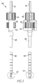
- FIG. 1 is a diagram illustrating an overall appearance of a drill bit 100 according to the present embodiment.
- the left-hand diagram is a front view and the right-hand diagram is a right-side view.
- a drill bit 100 includes an elongated member including a tubular portion 105 and a shaft-like portion 101 inserted in the tubular portion 105.
- An upper portion of the shaft-like portion 101 in the Figure is chucked to a non-illustrated drill motor and rotated, whereby cutting is performed at a distal end portion 107 of the drill bit 100.
- a grip 102 is fixed to the shaft-like portion 101 and formed integrally with the frame-like portion 103.
- the frame-like portion 103 has a hollow angular tubular shape, and receives a rotational operation portion 104 inside.
- the rotational operation portion 104 is provided so as to be rotatable relative to the shaft-like portion 101 and the frame-like portion 103.
- An inner portion of the rotational operation portion 104 is threaded, and the tubular portion 105 engages with the thread. By rotating the rotational operation portion 104, the tubular portion 105 moves in an axial direction thereof relative to the shaft-like portion 101.
- the tubular portion 105 On an outer peripheral surface of the tubular portion 105, marks 106 are provided at regular intervals. From the positions of the marks 106, the amount of the drill bit 100 inserted and the amount of the drill bit 100 pulled out after the insertion can be recognized. It is desirable that the drill bit 100 have a total length of approximately 300 mm and the tubular portion 105 have an outer diameter of 4.5 mm. This is because such sizes enable a bone hole having a diameter suitable for insertion of an endobutton to be formed in a femur.
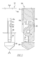
- Figure 2 includes enlarged diagrams in which a distal end portion 107 of the drill bit 100 has been enlarged.
- the left-hand diagram is an enlarged side view and the right-hand diagram is a cross-sectional view thereof taken along line A-A.
- a distal end cutter 203 is formed, and at a position closer to an operator relative to the distal end cutter 203, a slit 101a is provided.
- the slit 101a is an angular hole having a width smaller than an outer diameter of the shaft-like portion 101, and in a center portion thereof, a pin 204 is inserted.
- a blade 201 that includes two edges 201b and 201c and is rotatable about the pin 204 is attached to the pin 204.
- a groove portion 201a is formed, providing a mechanism in which a protruded portion 205, which is a part of the tubular portion 105, moves within the groove portion 201a.
- the protruded portion 205 makes the blade 201 pivot about the pin 204 while advancing within the groove portion 201a.
- the protruded portion 205 and the groove portion 201a function as a motion mechanism that converts a relative movement of the shaft-like portion 101 and the tubular portion 105 resulting from an operation of the rotational operation portion 104 to a pivoting of the blade 201 between a housed position and a projected position.
- the protruded portion 205 of the tubular portion 105 moves vertically and linearly, thereby a pressing force being imposed on an inner wall surface of the groove portion 201a, and the pressing force produces a turning force that turns the blade 201.
- the protruded portion 205 provides a turning force to the blade while moving within the groove portion 201a.
- the two edges 201b and 201c of the blade 201 move so as to project from slits 105a and 105b formed at a distal end of the tubular portion 105 to the outside of the tubular portion 105.
- the blade 201 is pivotable between a housed position where the blade 201 is housed in the elongated member of the drill bit, and a projected position where the edges 201b and 201c are projected outside the elongated member.
- Figure 3 includes diagrams each illustrating an outer appearance of the drill bit 100 when the blade 201 is brought out at the distal end portion 107 in Figure 1 .
- the left-hand diagram is a side view and the right-hand diagram is a front view.
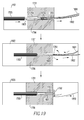
- the blade 201 is projected on sides in the distal end portion 307. In such state, the entire drill bit 100 is pulled back in the upward direction in the Figure while being rotated, enabling formation of a bone hole 1704 having a large diameter such as those illustrated in, e.g., Figures 16 and 20 .
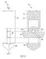
- Figure 4 includes diagrams in which the distal end portion 307 in Figure 3 has been enlarged: the left-hand one is a side view and the right-hand one is a cross-sectional diagram thereof taken along line B-B.
- the tubular portion 105 moves downward relative to the shaft-like portion 101, whereby the blade 201 receives a force of the protruded portion 205 and makes a right-hand turn in the Figure, and consequently, the edges 201b and 201c are stuck out of the tubular portion 105.
- the edges 201b and 201c are arranged in a direction perpendicular to an axis of the shaft-like portion 101.
- Figures 5 to 8 are diagrams each illustrating a component of the drill bit 100 when the drill bit 100 is disassembled: Figure 5 illustrates the shaft-like portion 101, Figure 6 illustrates a distal end of the shaft-like portion 101, Figure 7 illustrates the tubular portion 105, and Figure 8 illustrates the blade 201.
- Figure 5 includes a front view (501), an enlarged plan view (502), an enlarged bottom view (503) and a right-side view (504) of the shaft-like portion 101.
- an end of the shaft-like portion 101 includes a chuck portion 101b to be attached to the non-illustrated drill motor. Then, as has already been described with reference to Figure 2 , at another end of the shaft-like portion 101, the distal end cutter 203 and the slit 101a are formed.
- a through hole 101c for allowing the pin 204, which is a turning axis of the blade 201, to be fitted therein is formed.
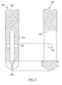
- Figure 6 illustrates an enlargement of a distal end portion 507 of the shaft-like portion 101 illustrated in Figure 5 .
- Figure 6 includes a cross-sectional diagram (601) illustrating an inner portion of the enlarged distal end portion and a cross-sectional diagram (602) thereof taken along line C-C.
- the slit 101a and the through hole 101c intersect each other in the inner portion of the shaft-like portion 101.
- the slit 101a is formed so as to have a size depending on the size of the blade 201 to be inserted therein.
- Figure 7 includes a front view diagram (701) and a bottom view diagram (702) of the tubular portion 105 and a cross-sectional diagram (703) thereof taken along line D-D.
- the tubular portion 105 includes the mutually facing slits 105a and 105b at the distal end thereof.
- the slit 105a is formed so as to have a width that is the same as that of the slit 105b and be longer than the slit 105b so that the blade 201 can vertically be housed.
- the protruded portion 205 is provided at a position somewhat below a center part of the slit 105a.
- the protruded portion 205 can be formed, for example, simultaneously with cutting the tubular portion 105 to form the slit 105a.
- Figure 8 includes a front view diagram (801), a left-side view diagram (802) and a bottom view diagram (803) of the blade 201.
- the blade 201 has a shape in which the two edges 201b and 201c are connected via a circular arc portion 201d.
- a through hole 201e for allowing the pin 204, which is a turning axis, to be loosely inserted therein.
- a bottom portion 201f is formed so as to be planar, and at a position somewhat inward of an end of the bottom portion 201f, an exit of the groove portion 201a is provided.
- the groove portion 201a is linearly provided from the exit toward the through hole 201e, and is formed so as to have a width allowing the protruded portion 205 of the tubular portion 105 to be inserted therein.
- Side portions 201g and 201h connecting the edges 201b and 201c, and the bottom portion 201f, of the blade 201 are each formed so as to have a curved surface so that the blade 201 does not interfere with the tubular portion 105 when turning about the pin 204.
- FIG 9 is an enlarged cross-sectional diagram of a handle portion of the drill bit 100 illustrated in Figure 1 .
- the grip 102 is fixed to the shaft-like portion 101 and is formed integrally with the frame-like portion 103.
- the frame-like portion 103 has a hollow angular tubular shape, and houses the rotational operation portion 104 inside.
- the rotational operation portion 104 is provided so as to be rotatable relative to the shaft-like portion 101 and the frame-like portion 103.
- a threaded block nut 901 is fitted in the inner portion of the rotational operation portion 104, and a guide portion 902 fixed to the outside of the tubular portion 105 engages with the thread.
- a force in the axial direction is transmitted to the guide portion 902 via the block nut 901, whereby the tubular portion 105 moves relative to the shaft-like portion 101 in the axial direction.
- the drill bit 100 configured as described above has a mechanism in which edges project on opposite sides of the tubular portion 105, enabling a double increase of the cutting efficiency and a decrease in vibration during cutting. Furthermore, the drill bit 100 has a favorable balance of loads relative to the axis, and thus, is difficult to break. In particular, where the drill bit 100 is used for drilling a hole in bone, while a vibration decrease is a very important issue, the vibration can substantially be decreased compared to a mechanism in which an edge projects only on one side of the tubular portion. Furthermore, wobbling of the axis is also reduced, and thus, a bone hole having a small diameter and a bone hole having a large diameter can accurately and coaxially be formed, enabling very smooth insertion of an endobutton.
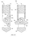
- Figure 10 includes cross-sectional diagrams (1010 and 1020) each illustrating a distal end portion of a drill bit according to the present embodiment, and the diagrams correspond to the cross-sectional diagrams (601 and 602) in Figure 6 .
- a blade 1001 includes a groove portion 1001a, and a protruded portion 205 moves within the groove portion 1001a, thereby the blade 1001 turns by 90 degrees relative to the tubular portion 105.
- two edges 1001b and 1001c included in the blade 1001 are formed at an angle so as to form a shape projecting toward the hands of an operator, not forming a straight line perpendicular to the axis of the shaft-like portion 101.
- center lines of edge surfaces of the edges 201b and 201c of the blade 201 lie on an identical straight line
- center lines of edge surfaces of the two edges 1001b and 1001c intersect each other at an acute angle.
- the blade 1001 is a plate having a shape of a rough isosceles triangle in its entirety, and the edges are provided on the two oblique sides of the isosceles triangle.
- the remaining configuration and functions are similar to those of the first embodiment, and thus, a description thereof will be omitted here.
- the present embodiment enables a decrease in resistance and vibration at the time of starting cutting. Furthermore, a bone hole having a large diameter can be formed so as to taper, enabling a tendon transplant to be fitted more firmly. Furthermore, situations where an endobutton is hung up during insertion can be reduced.
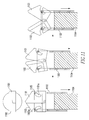
- FIG. 11 is a cross-sectional diagram illustrating changing of a distal end portion of a drill bit according to the present embodiment.
- the distal end of the drill bit includes two blade parts 1101 and 1102 pivotally supported by a shaft-like portion 1104. Then, a tubular portion 1103 moves relative to the shaft-like portion 1104, thereby the blade parts 1101 and 1102 being opened/closed.
- a blade includes a combination of two blade parts 1101 and 1102 each including one edge.
- the remaining configuration and functions are similar to those of the first embodiment, and thus, a description thereof will be omitted here.
- the blade parts 1101 and 1102 are in a closed state, and jointly form a distal end cutter.
- the drill bit is rotated in this state to advance upward in the Figure, enabling drilling a hole having a small diameter.
- the blade parts 1101 and 1102 each include a stepped end edge inside, which are fitted on each other and thereby integrated to function as a distal end cutter.
- the tubular portion 1103 is moved downward in the Figure relative to the shaft-like portion 1104 (toward an operator viewed from the operator), thereby the blade parts 1101 and 1102 start opening horizontally as illustrated in the center diagram.
- Protruded portions 1105 formed at the tubular portion 1103 move within groove portions 1101a and 1102a of the blade parts 1101 and 1102, respectively, thereby proving a force in the rightward direction in the Figure to the blade part 1101, and a force in the leftward direction in the Figure to the blade part 1102. This point is similar to the first and second embodiments.
- the blade parts 1101 and 1102 when the tubular portion 1103 is moved downward in the Figure relative to the shaft-like portion 1104, the blade parts 1101 and 1102 gradually open to enter the state illustrated in the right diagram in Figure 11 . Then, the blade parts 1101 and 1102 then change to the states in the left, center and right diagrams in Figure 12 . Lastly, as illustrated in the right diagram in Figure 12 , the blade parts 1101 and 1102 stick out on opposite sides of the tubular portion 1103. In this state, the drill bit is pulled toward the operator while being rotated, enabling holes having different sizes to be drilled at one time as in the first and second embodiments.
- two blades function as a distal end cutter, enabling a space for opening/closing the blades to be small.
- the present embodiment is used for knee ligament reconstruction, after formation of a bone hole having a small diameter, it is possible that the blades are extended with minimum insertion and a bone hole having a large diameter can be formed. In other words, the duration of surgery can substantially be reduced, and safer and less-invasive ligament reconstruction can be performed.
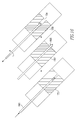
- FIGS. 13 and 14 are cross-sectional diagrams illustrating changing of a distal end portion of a drill bit according to the present embodiment:
- Figure 13 illustrates a state in which a blade 1302 is opened.
- Figure 14 illustrates a state in which the blade 1302 is closed.
- the protruded portion 205 provided at the tubular portion 105 and the groove portions 201a and 1001a of the respective blade 201 and 1001 engage with each other, thereby opening/closing the blade 201.
- an oblique surface (inner surface in an axial direction) of a slit 1306 provided in the tubular portion 1305 abuts to an edge or a surface opposite to the edge (i.e., a part of an outer peripheral surface) of the blade 1302, whereby the blade 1302 turns, opening/closing edges.
- a shaft-like portion 1301 is moved with the tubular portion 1305 fixed, thereby opening/closing the edges.
- the blade 1302 is pivotally supported by a pin 1304 fixed within a slit 1301a of the shaft-like portion 1301, and attached so that the blade 1302 can turn about the pin 1304.
- the shaft-like portion 1301 is moved upward in the Figure (toward the back viewed from an operator), whereby a surface of the slit 1306 formed at the tubular portion 1305, the surface being inclined to the distal end side toward an axis and the blade 1302 abut to each other, thereby a force that makes the blade 1302 has a right-hand turn in the Figure being imposed on the blade 1302. Consequently, the blade 1302 is housed as illustrated in the left diagram in Figure 14 .
- the shaft-like portion 1301 is moved downward in the Figure (toward an operator viewed from the operator), enabling the blade 1302 to be projected outside the tubular portion 1305 as illustrated in the right diagram in Figure 14 .
- a lower inclined surface of the slit 1306 abuts to an edge of the blade 1302, whereby the blade 1302 turns.
- the distal end cutter 1303 of the drill bit is fitted in and fixed to the tubular portion 1305.
- the configuration of the present embodiment is effective for a case where a drill bit has a smaller outer diameter or a case where a strength of the protruded portion 205 illustrated in Figure 2 cannot be ensured.
- the distal end cutter 1303 is fixed to the tubular portion 1305, and thus, a more strong drilling force can be exerted.
- FIG. 15 is a cross-sectional diagram of a distal end part of a drill bit according to the present embodiment.
- a thread insertion slit 1501 is provided in a blade 1502 in addition to the configuration of the fourth embodiment.
- threads 1801 and 1802 for manipulating an endobutton 1702 are hooked on the thread insertion slit 1501, the blade 1502 is closed and the drill bit is pulled out, whereby the threads 1801 and 1802 can be pulled out of the body. In other words, a process during surgery can be further reduced.
Landscapes
- Health & Medical Sciences (AREA)
- Surgery (AREA)
- Life Sciences & Earth Sciences (AREA)
- Biomedical Technology (AREA)
- Medical Informatics (AREA)
- Orthopedic Medicine & Surgery (AREA)
- Oral & Maxillofacial Surgery (AREA)
- Engineering & Computer Science (AREA)
- Dentistry (AREA)
- Heart & Thoracic Surgery (AREA)
- Nuclear Medicine, Radiotherapy & Molecular Imaging (AREA)
- Molecular Biology (AREA)
- Animal Behavior & Ethology (AREA)
- General Health & Medical Sciences (AREA)
- Public Health (AREA)
- Veterinary Medicine (AREA)
- Surgical Instruments (AREA)
- Knives (AREA)
- Drilling Tools (AREA)
Abstract
Description
- The present invention relates to a cutting technique for creating a hole in a solid body.
- Conventionally, there are various cutting instruments. Among them, drills for drilling of bone are subject to restrictive conditions such as being less-invasive and being used in a limited space in a body, and thus, are often required to have special functions.
- For example,
Patent Literatures 1 to 4 each disclose a method for forming a hole with a large diameter (hole allowing a tendon transplant to be inserted therein) inside a joint by pulling the cutting instrument toward an operator while rotating the cutting instrument in arthroscopic surgery, and a cutting instrument therefor. -
- [Patent Literature 1] US Patent Publication No.
US2010/0168750A1 - [Patent Literature 2] US Patent Publication No.
US2009/0275950A1 - [Patent Literature 3]
EP Patent Publication No. EP2098177A1 - [Patent Literature 4]
EP Patent No. 1987786 - However, the aforementioned conventional techniques each have a blade only on one side of a shaft of a rotating body, and thus, are poor in cutting efficiency and balance, causing vibration and failures.
- An object of the present invention is to provide a technique that solves the aforementioned problems.
- In order to achieve the above object, a cutting instrument according to the present invention provides
- a cutting instrument including:
- an elongated member including a tubular portion and a shaft-like portion inserted in the tubular portion;
- a blade including two edges and a center portion connecting the two edges, the blade being provided at an end of the elongated member and being pivotable between a housed position where the blade is housed in the elongated member and a projected position where the two edges are projected outside the elongated member, with the center portion as a pivot center;
- an operation portion provided at another end of the elongated member, the operation portion moving the tubular portion and the shaft-like portion relative to each other; and
- a motion mechanism that converts a relative movement of the tubular portion and the shaft-like portion resulting from an operation of the operation portion into pivoting of the blade between the housed position and the projected position,
- wherein the motion mechanism includes
- a groove portion provided in the blade, and
- a protruded portion provided at the tubular portion, the protruded portion giving a pivoting force to the blade while moving within the groove portion; and
- wherein the cutting instrument moves toward the operation portion while rotating in its entirety with the two edges of the blade projected on opposite sides of the tubular portion, thereby drilling a hole with a diameter larger than an outer diameter of the tubular portion.
- In order to achieve the above object, a cutting instrument according to the present invention includes:
- an elongated member including a tubular portion, and a shaft-like portion inserted in the tubular portion;
- a blade provided at an end of the elongated member, the blade including a pivot axis in a center thereof, and including an edge at each of two positions with the pivot shaft interposed therebetween;
- an operation portion provided at another end of the elongated member, the operation portion linearly moving the tubular portion and the shaft-like portion relative to each other; and
- a motion mechanism that converts a relative linear movement of the tubular portion and the shaft-like portion resulting from an operation of the operation portion into pivoting of the blade, the blade thereby pivoting between a housed position where the blade is housed in the elongated member, and a projected position where the edges are projected in two directions outside the elongated member,
- wherein the elongated member is moved toward the operation portion while being rotated with the edges of the blade projected from the elongated member, thereby drilling a hole having a diameter larger than an outer diameter of the tubular portion.
- The present invention enables achievement of cutting with a high cutting efficiency and a high stability.
-
- [
Figure 1] Figure 1 includes diagrams each illustrating an overall configuration of a cutting instrument according to a first embodiment of the present invention. - [
Figure 2] Figure 2 includes diagrams each illustrating a distal end configuration of the cutting instrument according to the first embodiment of the present invention. - [
Figure 3] Figure 3 includes diagrams each illustrating an overall configuration of the cutting instrument according to the first embodiment of the present invention. - [
Figure 4] Figure 4 includes diagrams each illustrating a distal end configuration of the cutting instrument according to the first embodiment of the present invention. - [
Figure 5] Figure 5 includes diagrams each illustrating a configuration of a shaft-like portion according to the first embodiment of the present invention. - [
Figure 6] Figure 6 includes diagrams each illustrating a distal end configuration of the shaft-like portion according to the first embodiment of the present invention. - [
Figure 7] Figure 7 includes diagrams each illustrating a distal end configuration of a tubular portion according to the first embodiment of the present invention. - [
Figure 8] Figure 8 includes diagrams each illustrating a configuration of a blade according to the first embodiment of the present invention. - [
Figure 9] Figure 9 is a diagram illustrating a configuration of an operation portion of the cutting instrument according to the first embodiment of the present invention. - [
Figure 10] Figure 10 includes diagrams each illustrating a configuration of a blade according to a second embodiment of the present invention. - [
Figure 11] Figure 11 includes diagrams each illustrating a configuration of a distal end portion according to a third embodiment of the present invention. - [
Figure 12] Figure 12 includes diagrams each illustrating a configuration of the distal end portion according to the third embodiment of the present invention. - [
Figure 13] Figure 13 includes diagrams each illustrating a configuration of a distal end portion according to a fourth embodiment of the present invention. - [
Figure 14] Figure 14 includes diagrams each illustrating a configuration of the distal end portion according to the fourth embodiment of the present invention. - [
Figure 15] Figure 15 is a diagram illustrating a configuration of a distal end portion according to a fifth embodiment of the present invention. - [
Figure 16] Figure 16 includes diagrams illustrating a method for bone drilling in ACL reconstruction. - [
Figure 17] Figure 17 is a diagram illustrating an example of ACL reconstruction. - [
Figure 18] Figure 18 is a diagram illustrating the example of ACL reconstruction. - [
Figure 19] Figure 19 includes diagrams illustrating the example of ACL reconstruction. - [
Figure 20] Figure 20 is a diagram illustrating another example of ACL reconstruction. - Hereinafter, exemplary embodiments of the present invention will be described in detail with reference to the drawings. However, components described in the below embodiments are mere exemplary ones, and are not intended to limit the technical scope of the present invention only to them.
- Before describing a drill bit, which is a first embodiment of a cutting instrument according to the present invention, knee ligament reconstruction will be described below as an example of usage of such a drill bit. However, the present invention is applicable not only to such knee ligament reconstruction but also to various situations of drilling a hole. In other words, the present invention can be used for drilling a hole in not only a bone, but also a solid body formed of any of various materials such as wood or metal.
- When an anterior cruciate ligament (ACL) or a posterior cruciate ligament (PCL) is ruptured and unrepairable, in general, a treatment involving transplantation of a graft of tissue (i.e., ACL reconstruction or PCL reconstruction) is conducted. Because of its improved performance of surgery and early recovery in rehabilitation, ACL reconstruction is a surgical operation that is most frequently conducted among knee joint surgical operations. The surgical method has drastically advanced in the recent ten years, enabling a surgical operation to be performed via a small cut using an arthroscope.
-
Figures 17 and18 are diagrams each illustrating an example of ACL reconstruction.Figure 17 is a perspective diagram illustrating afemur 1701 and atibia 1706 of aknee region 1700 of a right leg on the front side where the skin and muscles of theknee region 1700 are made transparent. Where an anterior cruciate ligament connecting thefemur 1701 and thetibia 1706 is ruptured,bone holes femur 1701 and thetibia 1706, respectively, and a tendon transplant (graft) 1705 is inserted into the bone holes and fixed, thereby reproducing a function of an anterior cruciate ligament. - In general, the
tendon transplant 1705 is obtained from, e.g., a part of a patellar tendon, and a semitendinous muscle and gracilis muscle, but may be formed from a synthetic material or a mixture of a synthetic material and a natural material. An end of thetendon transplant 1705 is inserted into thebone hole 1704 formed in thefemur 1701, and another end thereof is inserted into thebone hole 1707 formed in thetibia 1706. Each end of thetendon transplant 1705 is attached to anendobutton 1702, or a fixture such as aninterference screw 1708, and the fixture is fixed to a bone. - A method for using an
endobutton 1702 will be described with reference toFigure 19 . As illustrated in a diagram 1901 inFigure 19 , abone hole 1704 having a relatively large diameter (φ) 5 to φ 10 mm) for inserting atendon transplant 1705 therein is formed in afemur 1701. The diameter (thickness) of the tendon transplant is measured in advance, and a bone hole with a diameter corresponding (equal) to that size is created. Furthermore, where an endobutton 1702 (with a width of 4 mm) is used, abone hole 1703 having a small diameter (φ 4.5 mm) for allowing athread 1803 extending from thetendon transplant 1705 to the endobutton and theendobutton 1702 to pass therethrough. If thebone hole 1704 is excessively lager relative to thetendon transplant 1705, poor adherence between the bone and the tendon transplant occurs after the surgical operation, and thus, ordinarily, a bone hole for insertion of a tendon transplant is provided with a small diameter. Where a bone hole is formed from the inside of a joint, a bone hole having a length of a sum of a length of a femur tendon transplant to be inserted (ordinarily, 15 to 20 mm) and a length of 6 mm required for turning the endobutton is created. Next, twothreads endobutton 1702 are brought to the outside of the body from a subcutaneous tissue via thebone hole 1703 of thefemur 1701. - Then, the
endobutton 1702 is moved from the inside of the joint to the subcutaneous tissue via the bone holes 1704 and 1703 by mainly pulling thethread 1801. - As illustrated in a diagram 1902 in
Figure 19 , when theentire endobutton 1702 is brought out to the subcutaneous tissue, at that point of time, conversely, thethread 1801 is loosened while thethread 1802 is pulled. Consequently, theendobutton 1702 turns immediately outside thefemur 1701. - As illustrated in a diagram 1903 in
Figure 19 , where theendobutton 1702 turns by 90 degrees, theendobutton 1702 is caught by an exit of thebone hole 1703, and does not return to the inside of thefemur 1701, and at that point of time, thetendon transplant 1705 is fixed. Lastly, thethreads endobutton 1702, whereby attachment of thetendon transplant 1705 to thefemur 1701 side is completed. - For the
tendon transplant 1705, a hamstring (tendon behind a knee) and a patellar ligament (ligament connecting a knee cap and a tibia) are used.Figures 17 and18 illustrate a method in which one hole is created in a femur and one hole is created in a tibia, and a tendon is passed through the holes and fixed. However, recently, it has turned out that an anterior cruciate ligament is divided into two fibers, and thus, a method for reconstructing these two fibers (double bundle ACL reconstruction method) has been employed (Muneta 1999 and Yasuda 2006). In recent years, there are an increased number of reports that the double bundle ACL reconstruction method is more effective than the single bundle method in terms of recovery from anterior and rotary instability. In this double bundle ACL reconstruction method, a long tendon transplant is prepared using a hamstring, and two holes are created in a femur and two or three holes are created in a tibia to fix the tendon transplant therein (Anatomic Double Bundle ACL Reconstruction: Charles Crawford, John Nyland Sarah Landes, Richard Jackson, Haw Chong Chang, Akbar Nawab, David N. M. Caborn: Knee Surg Sports Traumatol Arthrosc (2007) 15, 946-964). -
Figure 20 illustrates aknee region 2000 after tendon transplantation according to the double bundle ACL reconstruction method. InFigure 20 , two tendon transplants, i.e., anteromedial band (AM band) 2005 and a posterolateral band (PL band) 1705 are reconstructed. The double bundle ACL reconstruction method requiresdrilling bone holes PL band 1705 anddrilling bone holes AM band 2005. Then, using the two endobuttons 1702 and 2002, thePL band 1705 and theAM band 2005 are fixed.Figure 20 illustrates a case where thePL band 1705 and theAM band 2005 are collectively fixed using astaple 2008 as a fixture on thetibia 1706 side. - As described above, in a knee ligament reconstruction surgical operation, it is said that a position where a tendon transplant is attached and the diameter of the tendon transplant are most important for the patient's early recovery and restoration close to a state before the tendon rupture. In other words, this definitely means that the positions, directions and sizes of the bone holes are important.
- Although in
Figure 17 , thebone hole 1707 formed in thetibia 1706 and thebone hole 1704 formed in thefemur 1701 are substantially coaxially formed, in reality, there may be cases where the linear attachment of thetendon transplant 1705 as illustrated inFigure 17 is undesirable from a somatological point of view. In other words, there are various restrictions on a position where thebone hole 1704 is created and the direction in which thebone hole 1704 is drilled, and thus, it is difficult to correctly and properly drill thebone hole 1704 on thefemur 1701 side, from thetibia 1706 side. - Therefore, in recent years, a method called "outside-in" in which a
bone hole 1704 is formed by drilling from the outside of thefemur 1701, not from thetibia 1706 side has been desired. However, since a very important quadriceps exists outside thefemur 1701, a hole with a large diameter cannot be created. Meanwhile, atendon transplant 1705 and abone hole 1704 for inserting thetendon transplant 1705 therein need to each have a certain diameter, and thus, with a bone hole having an extremely small diameter, atendon transplant 1705 cannot be reconstructed. In other words, with an ordinary method, co-axial continuous bone holes having different diameters (bulb socket-like bone hole) cannot be created. When an endobutton is used as a fixture, it is necessary to form a bone hole having a diameter (6 mm) that is half of the length of the endobutton, and thus, consequently, it is inevitable to make the tendon transplant itself thin, which may result in insufficiency in strength of the tendon transplant. - From the aforementioned facts, as illustrated in
Figure 16 , a surgical method in which after drilling a hole from the outside of afemur 1701 using adrill bit 1601 with a small diameter, thesame drill bit 1601 is kept inserted therein or another drill having a diameter that is substantially the same as that of thedrill bit 1601 is inserted, and ablade 1602 is brought out inside a joint, and abone hole 1704 having a large diameter is formed in an inner surface of thefemur 1701 while theblade 1602 is pulled toward an operator has been desired. - A cutting instrument, which is a first embodiment of the present invention, is a drill bit used in such a surgical method.
-
Figure 1 is a diagram illustrating an overall appearance of adrill bit 100 according to the present embodiment. The left-hand diagram is a front view and the right-hand diagram is a right-side view. Adrill bit 100 includes an elongated member including atubular portion 105 and a shaft-like portion 101 inserted in thetubular portion 105. An upper portion of the shaft-like portion 101 in the Figure is chucked to a non-illustrated drill motor and rotated, whereby cutting is performed at adistal end portion 107 of thedrill bit 100. - A
grip 102 is fixed to the shaft-like portion 101 and formed integrally with the frame-like portion 103. The frame-like portion 103 has a hollow angular tubular shape, and receives arotational operation portion 104 inside. Therotational operation portion 104 is provided so as to be rotatable relative to the shaft-like portion 101 and the frame-like portion 103. An inner portion of therotational operation portion 104 is threaded, and thetubular portion 105 engages with the thread. By rotating therotational operation portion 104, thetubular portion 105 moves in an axial direction thereof relative to the shaft-like portion 101. Here, a state in which thetubular portion 105 has been moved to a position closest to the hands of an operator (upper side in Figure) as a result of rotating therotational operation portion 104 in a closing direction (left-hand direction in the Figure). In other words, therotational operation portion 104, etc., function as an operation portion provided at another end of the elongated member, the operation portion moving the shaft-like portion 101 and thetubular portion 105 relative to each other. - On an outer peripheral surface of the
tubular portion 105, marks 106 are provided at regular intervals. From the positions of themarks 106, the amount of thedrill bit 100 inserted and the amount of thedrill bit 100 pulled out after the insertion can be recognized. It is desirable that thedrill bit 100 have a total length of approximately 300 mm and thetubular portion 105 have an outer diameter of 4.5 mm. This is because such sizes enable a bone hole having a diameter suitable for insertion of an endobutton to be formed in a femur. -
Figure 2 includes enlarged diagrams in which adistal end portion 107 of thedrill bit 100 has been enlarged. The left-hand diagram is an enlarged side view and the right-hand diagram is a cross-sectional view thereof taken along line A-A. At an end portion of the shaft-like portion 101, adistal end cutter 203 is formed, and at a position closer to an operator relative to thedistal end cutter 203, aslit 101a is provided. Theslit 101a is an angular hole having a width smaller than an outer diameter of the shaft-like portion 101, and in a center portion thereof, apin 204 is inserted. Ablade 201 that includes twoedges pin 204 is attached to thepin 204. At a surface of theblade 201, agroove portion 201a is formed, providing a mechanism in which a protrudedportion 205, which is a part of thetubular portion 105, moves within thegroove portion 201a. Upon thetubular portion 105 moving downward in the Figure, the protrudedportion 205 makes theblade 201 pivot about thepin 204 while advancing within thegroove portion 201a. The protrudedportion 205 and thegroove portion 201a function as a motion mechanism that converts a relative movement of the shaft-like portion 101 and thetubular portion 105 resulting from an operation of therotational operation portion 104 to a pivoting of theblade 201 between a housed position and a projected position. In other words, in the motion mechanism, the protrudedportion 205 of thetubular portion 105 moves vertically and linearly, thereby a pressing force being imposed on an inner wall surface of thegroove portion 201a, and the pressing force produces a turning force that turns theblade 201. In other words, the protrudedportion 205 provides a turning force to the blade while moving within thegroove portion 201a. - Consequently, the two
edges blade 201 move so as to project fromslits tubular portion 105 to the outside of thetubular portion 105. In other words, theblade 201 is pivotable between a housed position where theblade 201 is housed in the elongated member of the drill bit, and a projected position where theedges -
Figure 3 includes diagrams each illustrating an outer appearance of thedrill bit 100 when theblade 201 is brought out at thedistal end portion 107 inFigure 1 . As inFigure 1 , the left-hand diagram is a side view and the right-hand diagram is a front view. As illustrated inFigure 3 , theblade 201 is projected on sides in thedistal end portion 307. In such state, theentire drill bit 100 is pulled back in the upward direction in the Figure while being rotated, enabling formation of abone hole 1704 having a large diameter such as those illustrated in, e.g.,Figures 16 and20 . -
Figure 4 includes diagrams in which thedistal end portion 307 inFigure 3 has been enlarged: the left-hand one is a side view and the right-hand one is a cross-sectional diagram thereof taken along line B-B. As illustrated inFigure 4 , thetubular portion 105 moves downward relative to the shaft-like portion 101, whereby theblade 201 receives a force of the protrudedportion 205 and makes a right-hand turn in the Figure, and consequently, theedges tubular portion 105. Theedges like portion 101. -
Figures 5 to 8 are diagrams each illustrating a component of thedrill bit 100 when thedrill bit 100 is disassembled:Figure 5 illustrates the shaft-like portion 101,Figure 6 illustrates a distal end of the shaft-like portion 101,Figure 7 illustrates thetubular portion 105, andFigure 8 illustrates theblade 201. -
Figure 5 includes a front view (501), an enlarged plan view (502), an enlarged bottom view (503) and a right-side view (504) of the shaft-like portion 101. As illustrated in the front view (501), an end of the shaft-like portion 101 includes achuck portion 101b to be attached to the non-illustrated drill motor. Then, as has already been described with reference toFigure 2 , at another end of the shaft-like portion 101, thedistal end cutter 203 and theslit 101a are formed. Furthermore, as illustrated in the right-side view (504), at a side surface of the distal end of the shaft-like portion 101, a throughhole 101c for allowing thepin 204, which is a turning axis of theblade 201, to be fitted therein is formed. -
Figure 6 illustrates an enlargement of adistal end portion 507 of the shaft-like portion 101 illustrated inFigure 5 .Figure 6 includes a cross-sectional diagram (601) illustrating an inner portion of the enlarged distal end portion and a cross-sectional diagram (602) thereof taken along line C-C. As illustrated inFigure 6 , theslit 101a and the throughhole 101c intersect each other in the inner portion of the shaft-like portion 101. Theslit 101a is formed so as to have a size depending on the size of theblade 201 to be inserted therein. -
Figure 7 includes a front view diagram (701) and a bottom view diagram (702) of thetubular portion 105 and a cross-sectional diagram (703) thereof taken along line D-D. As illustrated in these diagrams, thetubular portion 105 includes the mutually facingslits slit 105a is formed so as to have a width that is the same as that of theslit 105b and be longer than theslit 105b so that theblade 201 can vertically be housed. At a position somewhat below a center part of theslit 105a, the protrudedportion 205 is provided. The protrudedportion 205 can be formed, for example, simultaneously with cutting thetubular portion 105 to form theslit 105a. -
Figure 8 includes a front view diagram (801), a left-side view diagram (802) and a bottom view diagram (803) of theblade 201. As illustrated in these diagrams, theblade 201 has a shape in which the twoedges circular arc portion 201d. At a center portion of thecircular arc portion 201d, a throughhole 201e for allowing thepin 204, which is a turning axis, to be loosely inserted therein. Abottom portion 201f is formed so as to be planar, and at a position somewhat inward of an end of thebottom portion 201f, an exit of thegroove portion 201a is provided. Thegroove portion 201a is linearly provided from the exit toward the throughhole 201e, and is formed so as to have a width allowing the protrudedportion 205 of thetubular portion 105 to be inserted therein.Side portions edges bottom portion 201f, of theblade 201 are each formed so as to have a curved surface so that theblade 201 does not interfere with thetubular portion 105 when turning about thepin 204. -
Figure 9 is an enlarged cross-sectional diagram of a handle portion of thedrill bit 100 illustrated inFigure 1 . Thegrip 102 is fixed to the shaft-like portion 101 and is formed integrally with the frame-like portion 103. The frame-like portion 103 has a hollow angular tubular shape, and houses therotational operation portion 104 inside. Therotational operation portion 104 is provided so as to be rotatable relative to the shaft-like portion 101 and the frame-like portion 103. A threadedblock nut 901 is fitted in the inner portion of therotational operation portion 104, and aguide portion 902 fixed to the outside of thetubular portion 105 engages with the thread. By rotating therotational operation portion 104, a force in the axial direction is transmitted to theguide portion 902 via theblock nut 901, whereby thetubular portion 105 moves relative to the shaft-like portion 101 in the axial direction. - The
drill bit 100 configured as described above has a mechanism in which edges project on opposite sides of thetubular portion 105, enabling a double increase of the cutting efficiency and a decrease in vibration during cutting. Furthermore, thedrill bit 100 has a favorable balance of loads relative to the axis, and thus, is difficult to break. In particular, where thedrill bit 100 is used for drilling a hole in bone, while a vibration decrease is a very important issue, the vibration can substantially be decreased compared to a mechanism in which an edge projects only on one side of the tubular portion. Furthermore, wobbling of the axis is also reduced, and thus, a bone hole having a small diameter and a bone hole having a large diameter can accurately and coaxially be formed, enabling very smooth insertion of an endobutton. - A drill bit, which is a second embodiment of the present invention, will be described with reference to
Figure 10. Figure 10 includes cross-sectional diagrams (1010 and 1020) each illustrating a distal end portion of a drill bit according to the present embodiment, and the diagrams correspond to the cross-sectional diagrams (601 and 602) inFigure 6 . In the present embodiment, also, ablade 1001 includes agroove portion 1001a, and a protrudedportion 205 moves within thegroove portion 1001a, thereby theblade 1001 turns by 90 degrees relative to thetubular portion 105. - However, as opposed to the first embodiment, in the present embodiment, two
edges blade 1001 are formed at an angle so as to form a shape projecting toward the hands of an operator, not forming a straight line perpendicular to the axis of the shaft-like portion 101. In other words, while in the first embodiment, center lines of edge surfaces of theedges blade 201 lie on an identical straight line, in the present embodiment, center lines of edge surfaces of the twoedges blade 1001 is a plate having a shape of a rough isosceles triangle in its entirety, and the edges are provided on the two oblique sides of the isosceles triangle. The remaining configuration and functions are similar to those of the first embodiment, and thus, a description thereof will be omitted here. - The present embodiment enables a decrease in resistance and vibration at the time of starting cutting. Furthermore, a bone hole having a large diameter can be formed so as to taper, enabling a tendon transplant to be fitted more firmly. Furthermore, situations where an endobutton is hung up during insertion can be reduced.
- A drill bit, which is a third embodiment of the present invention, will be described with reference to
Figures 11 and12 .Figure 11 is a cross-sectional diagram illustrating changing of a distal end portion of a drill bit according to the present embodiment. As opposed to the first and second embodiments, the distal end of the drill bit includes twoblade parts like portion 1104. Then, atubular portion 1103 moves relative to the shaft-like portion 1104, thereby theblade parts blade parts - In the left-hand diagram in
Figure 11 , theblade parts blade parts - Meanwhile, the
tubular portion 1103 is moved downward in the Figure relative to the shaft-like portion 1104 (toward an operator viewed from the operator), thereby theblade parts Protruded portions 1105 formed at thetubular portion 1103 move withingroove portions blade parts blade part 1101, and a force in the leftward direction in the Figure to theblade part 1102. This point is similar to the first and second embodiments. - Furthermore, when the
tubular portion 1103 is moved downward in the Figure relative to the shaft-like portion 1104, theblade parts Figure 11 . Then, theblade parts Figure 12 . Lastly, as illustrated in the right diagram inFigure 12 , theblade parts tubular portion 1103. In this state, the drill bit is pulled toward the operator while being rotated, enabling holes having different sizes to be drilled at one time as in the first and second embodiments. - According to the present embodiment, two blades function as a distal end cutter, enabling a space for opening/closing the blades to be small. In other words, if the present embodiment is used for knee ligament reconstruction, after formation of a bone hole having a small diameter, it is possible that the blades are extended with minimum insertion and a bone hole having a large diameter can be formed. In other words, the duration of surgery can substantially be reduced, and safer and less-invasive ligament reconstruction can be performed.
- A drill bit, which is a fourth embodiment of the present invention, will be described with reference to
Figures 13 and14 .Figures 13 and14 are cross-sectional diagrams illustrating changing of a distal end portion of a drill bit according to the present embodiment:Figure 13 illustrates a state in which ablade 1302 is opened.Figure 14 illustrates a state in which theblade 1302 is closed. In the first and second embodiments, the protrudedportion 205 provided at thetubular portion 105 and thegroove portions respective blade blade 201. Meanwhile, in the present embodiment, an oblique surface (inner surface in an axial direction) of aslit 1306 provided in thetubular portion 1305 abuts to an edge or a surface opposite to the edge (i.e., a part of an outer peripheral surface) of theblade 1302, whereby theblade 1302 turns, opening/closing edges. As opposed to the first to third embodiments, a shaft-like portion 1301 is moved with thetubular portion 1305 fixed, thereby opening/closing the edges. - In
Figure 13 , as in the first and second embodiments, theblade 1302 is pivotally supported by apin 1304 fixed within aslit 1301a of the shaft-like portion 1301, and attached so that theblade 1302 can turn about thepin 1304. The shaft-like portion 1301 is moved upward in the Figure (toward the back viewed from an operator), whereby a surface of theslit 1306 formed at thetubular portion 1305, the surface being inclined to the distal end side toward an axis and theblade 1302 abut to each other, thereby a force that makes theblade 1302 has a right-hand turn in the Figure being imposed on theblade 1302. Consequently, theblade 1302 is housed as illustrated in the left diagram inFigure 14 . Meanwhile, the shaft-like portion 1301 is moved downward in the Figure (toward an operator viewed from the operator), enabling theblade 1302 to be projected outside thetubular portion 1305 as illustrated in the right diagram inFigure 14 . In this case, a lower inclined surface of theslit 1306 abuts to an edge of theblade 1302, whereby theblade 1302 turns. Meanwhile, in the present embodiment, thedistal end cutter 1303 of the drill bit is fitted in and fixed to thetubular portion 1305. - The configuration of the present embodiment is effective for a case where a drill bit has a smaller outer diameter or a case where a strength of the protruded
portion 205 illustrated inFigure 2 cannot be ensured. Thedistal end cutter 1303 is fixed to thetubular portion 1305, and thus, a more strong drilling force can be exerted. - A fifth embodiment of the present invention will be described with reference to
Figure 15. Figure 15 is a cross-sectional diagram of a distal end part of a drill bit according to the present embodiment. In the present embodiment, athread insertion slit 1501 is provided in a blade 1502 in addition to the configuration of the fourth embodiment. After formation of abone hole 1704,threads endobutton 1702 are hooked on thethread insertion slit 1501, the blade 1502 is closed and the drill bit is pulled out, whereby thethreads -
- 100
- drill bit
- 101, 1104, 1301
- shaft-like portion
- 102
- grip
- 103
- frame-like portion
- 104
- rotational operation portion
- 105, 1103, 1305
- tubular portion
- 106
- mark
- 201, 1001, 1101, 1102, 1302, 1502
- blade
- 203, 1303
- distal end cutter
- 204, 1304
- pin
- 205, 1105
- protruded portion
- 901
- block nut
- 902
- guide portion
- 1501
- thread insertion slit
Claims (5)
- A cutting instrument comprising:an elongated member including a tubular portion, and a shaft-like portion inserted in the tubular portion;a blade provided at an end of the elongated member, the blade including a pivot axis in a center thereof, and including an edge at each of two positions with the pivot shaft interposed therebetween;an operation portion provided at another end of the elongated member, the operation portion linearly moving the tubular portion and the shaft-like portion relative to each other; anda motion mechanism that converts a relative linear movement of the tubular portion and the shaft-like portion resulting from an operation of the operation portion into pivoting of the blade, the blade thereby pivoting between a housed position where the blade is housed in the elongated member, and a projected position where the edges are projected in two directions outside the elongated member,wherein the elongated member is moved toward the operation portion while being rotated with the edges of the blade projected from the elongated member, thereby drilling a hole having a diameter larger than an outer diameter of the tubular portion.
- The cutting instrument according to claim 4, wherein the blade is a plate-like member including an edge at each of two positions with the pivot axis interposed therebetween.
- The cutting instrument according to claim 4 or 5,
wherein the motion mechanism includes
an outer peripheral surface of the blade, and
an inner surface in an axial direction of a slit provided in the tubular portion, the slit being formed so as to have a width larger than a thickness of the blade; and
wherein the outer peripheral surface abuts the inner surface in the axial direction of the slit, the blade thereby pivoting between the housed position and the projected position. - The cutting instrument according to any one of claims 4 to 6,
wherein the blade includes a first edge and a second edge at two positions with the pivot axis interposed therebetween; and
wherein a center line of an edge surface of the first edge and a center line of an edge surface of the second edge lie on an identical straight line. - The cutting instrument according to any one of claims 4 to 7,
wherein the blade includes a first edge and a second edge at two positions with the pivot axis interposed therebetween; and wherein a center line of an edge surface of the first edge and a center line of an edge surface of the second edge intersect with each other.
Applications Claiming Priority (3)
| Application Number | Priority Date | Filing Date | Title |
|---|---|---|---|
| JP2011053838A JP4801225B1 (en) | 2011-03-11 | 2011-03-11 | Cutting tools |
| JP2011170653A JP5819669B2 (en) | 2011-08-04 | 2011-08-04 | Cutting tools |
| EP12712465.9A EP2683307B1 (en) | 2011-03-11 | 2012-03-12 | Cutting instrument |
Related Parent Applications (2)
| Application Number | Title | Priority Date | Filing Date |
|---|---|---|---|
| EP12712465.9A Division-Into EP2683307B1 (en) | 2011-03-11 | 2012-03-12 | Cutting instrument |
| EP12712465.9A Division EP2683307B1 (en) | 2011-03-11 | 2012-03-12 | Cutting instrument |
Publications (2)
| Publication Number | Publication Date |
|---|---|
| EP2823778A1 true EP2823778A1 (en) | 2015-01-14 |
| EP2823778B1 EP2823778B1 (en) | 2017-08-09 |
Family
ID=45931012
Family Applications (2)
| Application Number | Title | Priority Date | Filing Date |
|---|---|---|---|
| EP12712465.9A Not-in-force EP2683307B1 (en) | 2011-03-11 | 2012-03-12 | Cutting instrument |
| EP14170888.3A Not-in-force EP2823778B1 (en) | 2011-03-11 | 2012-03-12 | Cutting instrument |
Family Applications Before (1)
| Application Number | Title | Priority Date | Filing Date |
|---|---|---|---|
| EP12712465.9A Not-in-force EP2683307B1 (en) | 2011-03-11 | 2012-03-12 | Cutting instrument |
Country Status (10)
| Country | Link |
|---|---|
| US (2) | US9655629B2 (en) |
| EP (2) | EP2683307B1 (en) |
| KR (1) | KR20170051553A (en) |
| CN (1) | CN103764047B (en) |
| AU (1) | AU2012229213B2 (en) |
| BR (1) | BR112013022976A2 (en) |
| MX (1) | MX338809B (en) |
| RU (1) | RU2602721C2 (en) |
| WO (1) | WO2012125546A1 (en) |
| ZA (1) | ZA201306374B (en) |
Cited By (2)
| Publication number | Priority date | Publication date | Assignee | Title |
|---|---|---|---|---|
| WO2018213070A3 (en) * | 2017-05-16 | 2019-01-03 | Arthrex, Inc. | Expandable reamers |
| DE102022130147A1 (en) * | 2022-11-15 | 2024-05-16 | Aesculap Ag | Surgical tool, surgical handpiece and manufacturing process for a surgical tool |
Families Citing this family (23)
| Publication number | Priority date | Publication date | Assignee | Title |
|---|---|---|---|---|
| US10357259B2 (en) * | 2012-12-05 | 2019-07-23 | Smith & Nephew, Inc. | Surgical instrument |
| CN103340681B (en) * | 2013-06-28 | 2015-01-21 | 四川大学华西医院 | Full arthroscopic Inlay technique for posterior cruciate ligament reconstruction with tibial slotter |
| CA2927436C (en) * | 2013-10-15 | 2022-04-26 | Stryker Corporation | Device for creating a void space in living tissue, the device including a handle with a control knob that can be set regardless of the orientation of the handle |
| US9603607B2 (en) | 2014-03-11 | 2017-03-28 | Lenkbar, Llc | Reaming instrument with adjustable profile |
| US9517076B2 (en) | 2014-03-11 | 2016-12-13 | Lenkbar, Llc | Reaming instrument with adjustable profile |
| US9243881B2 (en) | 2014-05-29 | 2016-01-26 | Smith & Nephew, Inc. | Retrograde reamer depth tub gage |
| MX2016015643A (en) * | 2014-05-29 | 2017-08-16 | Smith & Nephew Inc | Retrogade reamer depth tube gage. |
| US9795395B2 (en) | 2014-06-10 | 2017-10-24 | Medos International Sarl | Retro-cutting instrument with adjustable limit setting |
| US10258484B2 (en) * | 2014-06-12 | 2019-04-16 | Limacorporate S.P.A. | Instrument for the removal of a bone insert and corresponding method |
| EP3197374A4 (en) * | 2014-09-25 | 2018-06-13 | David G. Matsuura | Drill depth measuring devices and methods |
| US10398416B2 (en) | 2014-10-01 | 2019-09-03 | Smith & Nephew, Inc. | Bone marrow lesion drill |
| GB201504854D0 (en) * | 2015-03-23 | 2015-05-06 | Depuy Ireland | A attachment mechanism for a surgical instrument component |
| FR3036029B1 (en) * | 2015-05-12 | 2020-05-22 | L.A.R.S. - Laboratoire D'application Et De Recherche Scientifique | MILLING MILL |
| US10743912B2 (en) | 2015-11-17 | 2020-08-18 | Lenkbar, Llc | Surgical tunneling instrument with expandable section |
| FR3043903A1 (en) * | 2015-11-20 | 2017-05-26 | Amplitude | RETROPERCAGE ANCILLARY AND BONE PREPARATION ASSEMBLY COMPRISING SUCH A RETROPERCAGE ANCILLARY |
| US10492800B2 (en) * | 2015-11-25 | 2019-12-03 | Lenkbar, Llc | Bone cutting instrument with expandable section |
| DE102016105431A1 (en) * | 2016-03-23 | 2017-09-28 | Aesculap Ag | Medical device |
| EP3248552A1 (en) * | 2016-05-25 | 2017-11-29 | WALDEMAR LINK GmbH & Co. KG | Tool for the production of a recess in bone tissue |
| IT201600116509A1 (en) * | 2016-11-17 | 2018-05-17 | Medacta Int Sa | GUIDE FOR INTRAMIDOLLAR REAMER |
| EP3638132A1 (en) * | 2017-06-12 | 2020-04-22 | ConMed Corporation | Orthopedic drill bit with swiveling head |
| EP3958752B1 (en) | 2019-04-24 | 2025-03-12 | Stryker Corporation | Systems for off-axis augmentation of a vertebral body |
| EP4059449A1 (en) * | 2021-03-15 | 2022-09-21 | Fundación Tecnalia Research & Innovation | Expansive drill and method for drilling a hole using said expansive drill |
| DE102021001608B4 (en) * | 2021-03-26 | 2025-01-23 | Mimeo Medical Gmbh | surgical drilling instrument |
Citations (8)
| Publication number | Priority date | Publication date | Assignee | Title |
|---|---|---|---|---|
| WO2006074321A2 (en) * | 2003-11-20 | 2006-07-13 | Arthrosurface, Inc. | System and method for retrograde procedure |
| EP1987786A2 (en) | 2007-05-02 | 2008-11-05 | Arthrex, Inc. | Flip retrograde cutting instrument |
| EP2098177A1 (en) | 2008-03-03 | 2009-09-09 | Arthrex Inc. | Combined flip cutter and drill |
| US20090275950A1 (en) | 2007-05-02 | 2009-11-05 | Arthrex, Inc. | Flip retrograde cutting instrument |
| WO2010013027A1 (en) * | 2008-07-29 | 2010-02-04 | Depuy International Ltd | An instrument for forming a cavity within a bone |
| US20100036381A1 (en) * | 2008-08-07 | 2010-02-11 | Ryan Vanleeuwen | Cavity creator with integral cement delivery lumen |
| US20100168750A1 (en) | 2007-05-02 | 2010-07-01 | Arthrex,Inc. | Retrograde cutter with rotating blade |
| EP2218411A1 (en) * | 2008-12-29 | 2010-08-18 | Arthrex, Inc. | Retrograde cutter with rotating blade |
Family Cites Families (24)
| Publication number | Priority date | Publication date | Assignee | Title |
|---|---|---|---|---|
| US2438558A (en) * | 1944-09-15 | 1948-03-30 | St Nils Bertil Fredr Holiander | Levelling tool |
| US3827821A (en) * | 1973-04-09 | 1974-08-06 | H Swenson | Axially actuated back spot facing tool |
| US4307636A (en) | 1980-03-31 | 1981-12-29 | Drillco Devices Limited | Undercutting tool |
| US4475852A (en) | 1981-12-24 | 1984-10-09 | Santrade Ltd. | Retractable rotary cutting tool |
| US6503277B2 (en) | 1991-08-12 | 2003-01-07 | Peter M. Bonutti | Method of transplanting human body tissue |
| IL108659A (en) | 1994-02-16 | 1997-11-20 | Noga Eng Ltd | Reversible countersink |
| US5591170A (en) | 1994-10-14 | 1997-01-07 | Genesis Orthopedics | Intramedullary bone cutting saw |
| US5817095A (en) | 1996-02-22 | 1998-10-06 | Smith & Nephew, Inc. | Undercutting surgical instrument |
| US6102934A (en) * | 1998-06-02 | 2000-08-15 | Li; Lehmann K. | Anchor tool and method and apparatus for emplacing anchor in a borehole |
| US6679886B2 (en) | 2000-09-01 | 2004-01-20 | Synthes (Usa) | Tools and methods for creating cavities in bone |
| US6648894B2 (en) | 2000-12-21 | 2003-11-18 | Stryker Spine | Bone graft forming guide and method of forming bone grafts |
| US7238189B2 (en) | 2003-03-18 | 2007-07-03 | Arthrex, Inc. | ACL reconstruction technique using retrodrill |
| JP2006523542A (en) | 2003-04-17 | 2006-10-19 | セカント メディカル エルエルシー | Tool with expandable cutting edge |
| EP1663029A4 (en) | 2003-09-03 | 2010-06-09 | Kyphon Sarl | DEVICES FOR CREATING CAVITIES IN INTERNAL BODY AREAS AND ASSOCIATED METHODS |
| US7951163B2 (en) | 2003-11-20 | 2011-05-31 | Arthrosurface, Inc. | Retrograde excision system and apparatus |
| EP1785103B1 (en) | 2005-11-10 | 2010-09-15 | Arthrex, Inc. | Apparatus for anterior cruciate ligament (ACL) reconstruction using rotary drill cutter to form retrograde sockets |
| FR2898484B1 (en) * | 2006-03-16 | 2009-02-27 | Fournitures Hospitalieres Ind | TOOL FOR MAKING A BORING INTO A BONE |
| CN200974138Y (en) * | 2006-10-31 | 2007-11-14 | 扬动股份有限公司 | Reverse countersink drill |
| US8206391B2 (en) | 2007-03-07 | 2012-06-26 | Vertech, Inc. | Expandable blade device for stabilizing compression fractures |
| US8388621B2 (en) | 2008-03-06 | 2013-03-05 | Smith & Nephew, Inc. | Retrodrill system |
| US20110144678A1 (en) * | 2009-12-15 | 2011-06-16 | Slater Charles R | Endoscopic Scissors Instrument |
| CN201617897U (en) * | 2010-03-12 | 2010-11-03 | 北京市富乐科技开发有限公司 | Dual-purpose femoral head single-knife sneaking drilling and expanding device |
| JP4801225B1 (en) | 2011-03-11 | 2011-10-26 | アリオメディカル株式会社 | Cutting tools |
| US9545261B2 (en) | 2011-07-29 | 2017-01-17 | Smith & Nephew, Inc. | Instrument guide |
-
2012
- 2012-03-12 BR BR112013022976A patent/BR112013022976A2/en not_active Application Discontinuation
- 2012-03-12 MX MX2013010385A patent/MX338809B/en active IP Right Grant
- 2012-03-12 EP EP12712465.9A patent/EP2683307B1/en not_active Not-in-force
- 2012-03-12 RU RU2013144965/14A patent/RU2602721C2/en not_active IP Right Cessation
- 2012-03-12 CN CN201280012828.8A patent/CN103764047B/en not_active Expired - Fee Related
- 2012-03-12 AU AU2012229213A patent/AU2012229213B2/en not_active Ceased
- 2012-03-12 KR KR1020137026237A patent/KR20170051553A/en not_active Ceased
- 2012-03-12 EP EP14170888.3A patent/EP2823778B1/en not_active Not-in-force
- 2012-03-12 US US14/004,398 patent/US9655629B2/en not_active Expired - Fee Related
- 2012-03-12 WO PCT/US2012/028750 patent/WO2012125546A1/en not_active Ceased
-
2013
- 2013-08-23 ZA ZA2013/06374A patent/ZA201306374B/en unknown
-
2017
- 2017-05-11 US US15/593,118 patent/US9924951B2/en not_active Expired - Fee Related
Patent Citations (8)
| Publication number | Priority date | Publication date | Assignee | Title |
|---|---|---|---|---|
| WO2006074321A2 (en) * | 2003-11-20 | 2006-07-13 | Arthrosurface, Inc. | System and method for retrograde procedure |
| EP1987786A2 (en) | 2007-05-02 | 2008-11-05 | Arthrex, Inc. | Flip retrograde cutting instrument |
| US20090275950A1 (en) | 2007-05-02 | 2009-11-05 | Arthrex, Inc. | Flip retrograde cutting instrument |
| US20100168750A1 (en) | 2007-05-02 | 2010-07-01 | Arthrex,Inc. | Retrograde cutter with rotating blade |
| EP2098177A1 (en) | 2008-03-03 | 2009-09-09 | Arthrex Inc. | Combined flip cutter and drill |
| WO2010013027A1 (en) * | 2008-07-29 | 2010-02-04 | Depuy International Ltd | An instrument for forming a cavity within a bone |
| US20100036381A1 (en) * | 2008-08-07 | 2010-02-11 | Ryan Vanleeuwen | Cavity creator with integral cement delivery lumen |
| EP2218411A1 (en) * | 2008-12-29 | 2010-08-18 | Arthrex, Inc. | Retrograde cutter with rotating blade |
Non-Patent Citations (1)
| Title |
|---|
| CHARLES CRAWFORD; JOHN NYLAND; SARAH LANDES; RICHARD JACKSON; HAW CHONG CHANG; AKBAR NAWAB; DAVID N. M. CABORN: "Anatomic Double Bundle ACL Reconstruction", KNEE SURG SPORTS TRAUMATOL ARTHROSC, vol. 15, 2007, pages 946 - 964 |
Cited By (4)
| Publication number | Priority date | Publication date | Assignee | Title |
|---|---|---|---|---|
| WO2018213070A3 (en) * | 2017-05-16 | 2019-01-03 | Arthrex, Inc. | Expandable reamers |
| US10456145B2 (en) | 2017-05-16 | 2019-10-29 | Arthrex, Inc. | Expandable reamers |
| US11376020B2 (en) | 2017-05-16 | 2022-07-05 | Arthrex, Inc. | Expandable reamers |
| DE102022130147A1 (en) * | 2022-11-15 | 2024-05-16 | Aesculap Ag | Surgical tool, surgical handpiece and manufacturing process for a surgical tool |
Also Published As
| Publication number | Publication date |
|---|---|
| US9924951B2 (en) | 2018-03-27 |
| MX338809B (en) | 2016-04-29 |
| CN103764047B (en) | 2016-10-19 |
| US9655629B2 (en) | 2017-05-23 |
| MX2013010385A (en) | 2014-03-27 |
| EP2683307B1 (en) | 2016-12-14 |
| CN103764047A (en) | 2014-04-30 |
| US20140207142A1 (en) | 2014-07-24 |
| ZA201306374B (en) | 2014-04-30 |
| EP2823778B1 (en) | 2017-08-09 |
| WO2012125546A1 (en) | 2012-09-20 |
| AU2012229213A1 (en) | 2013-09-12 |
| RU2602721C2 (en) | 2016-11-20 |
| AU2012229213B2 (en) | 2016-04-14 |
| EP2683307A1 (en) | 2014-01-15 |
| US20170303933A1 (en) | 2017-10-26 |
| KR20170051553A (en) | 2017-05-12 |
| RU2013144965A (en) | 2015-04-20 |
| BR112013022976A2 (en) | 2016-12-06 |
Similar Documents
| Publication | Publication Date | Title |
|---|---|---|
| EP2823778B1 (en) | Cutting instrument | |
| JP5819669B2 (en) | Cutting tools | |
| JP4801225B1 (en) | Cutting tools | |
| US11744596B2 (en) | Retrograde cutting instrument | |
| EP2072015B1 (en) | Surgical drill for providing holes at an angle | |
| CN104042310B (en) | For the femur orthopaedic instrumentation component for the biasing that shapes | |
| US8652139B2 (en) | Flip retrograde cutting instrument | |
| EP2286769B1 (en) | Arthroscopic tibial sizer | |
| CN104042308B (en) | Shin bone orthopaedic instrumentation for the biasing that shapes | |
| EP2692298B1 (en) | Surgical instruments with a cannulated, resilient bushing | |
| EP2729080B1 (en) | Orthopedic instruments | |
| RU2632541C2 (en) | Replaceable stapling head, replaceable needle cartridge and staple | |
| US9820754B2 (en) | Circular bone tunneling device employing a stabilizing element | |
| CN104042256B (en) | Femur orthopaedic instrumentation for the biasing that shapes | |
| US20170202567A1 (en) | System and Method for Forming a Curved Tunnel in Bone | |
| US20050228399A1 (en) | Guiding device for use in anterior cruciate knee ligament reconstruction | |
| EP2286742A1 (en) | Flexible ACL instrumentation, kit and method | |
| KR102035651B1 (en) | Surgical instrument for reconstruction of shoulder ligament | |
| US20160317162A1 (en) | Methods and systems for ligament repair | |
| JP2016140487A (en) | Surgical instrument for artificial knee joint replacement | |
| US12144511B2 (en) | Retrograde cutting instrument | |
| US9717491B2 (en) | Method and apparatus for coupling soft tissue to bone | |
| CN115252239A (en) | needle guide mechanism | |
| KR20230093855A (en) | Transosseous Surgical Instrument | |
| CN114191014A (en) | Meniscus stitching instrument capable of rotating from inside to outside to inside |
Legal Events
| Date | Code | Title | Description |
|---|---|---|---|
| 17P | Request for examination filed |
Effective date: 20140603 |
|
| AC | Divisional application: reference to earlier application |
Ref document number: 2683307 Country of ref document: EP Kind code of ref document: P |
|
| AK | Designated contracting states |
Kind code of ref document: A1 Designated state(s): AL AT BE BG CH CY CZ DE DK EE ES FI FR GB GR HR HU IE IS IT LI LT LU LV MC MK MT NL NO PL PT RO RS SE SI SK SM TR |
|
| PUAI | Public reference made under article 153(3) epc to a published international application that has entered the european phase |
Free format text: ORIGINAL CODE: 0009012 |
|
| R17P | Request for examination filed (corrected) |
Effective date: 20150714 |
|
| RBV | Designated contracting states (corrected) |
Designated state(s): AL AT BE BG CH CY CZ DE DK EE ES FI FR GB GR HR HU IE IS IT LI LT LU LV MC MK MT NL NO PL PT RO RS SE SI SK SM TR |
|
| GRAP | Despatch of communication of intention to grant a patent |
Free format text: ORIGINAL CODE: EPIDOSNIGR1 |
|
| INTG | Intention to grant announced |
Effective date: 20170222 |
|
| GRAS | Grant fee paid |
Free format text: ORIGINAL CODE: EPIDOSNIGR3 |
|
| GRAA | (expected) grant |
Free format text: ORIGINAL CODE: 0009210 |
|
| AC | Divisional application: reference to earlier application |
Ref document number: 2683307 Country of ref document: EP Kind code of ref document: P |
|
| AK | Designated contracting states |
Kind code of ref document: B1 Designated state(s): AL AT BE BG CH CY CZ DE DK EE ES FI FR GB GR HR HU IE IS IT LI LT LU LV MC MK MT NL NO PL PT RO RS SE SI SK SM TR |
|
| REG | Reference to a national code |
Ref country code: GB Ref legal event code: FG4D |
|
| REG | Reference to a national code |
Ref country code: CH Ref legal event code: EP Ref country code: AT Ref legal event code: REF Ref document number: 915940 Country of ref document: AT Kind code of ref document: T Effective date: 20170815 |
|
| REG | Reference to a national code |
Ref country code: IE Ref legal event code: FG4D |
|
| REG | Reference to a national code |
Ref country code: DE Ref legal event code: R096 Ref document number: 602012035876 Country of ref document: DE |
|
| REG | Reference to a national code |
Ref country code: NL Ref legal event code: MP Effective date: 20170809 |
|
| REG | Reference to a national code |
Ref country code: LT Ref legal event code: MG4D |
|
| REG | Reference to a national code |
Ref country code: AT Ref legal event code: MK05 Ref document number: 915940 Country of ref document: AT Kind code of ref document: T Effective date: 20170809 |
|
| PG25 | Lapsed in a contracting state [announced via postgrant information from national office to epo] |
Ref country code: NO Free format text: LAPSE BECAUSE OF FAILURE TO SUBMIT A TRANSLATION OF THE DESCRIPTION OR TO PAY THE FEE WITHIN THE PRESCRIBED TIME-LIMIT Effective date: 20171109 Ref country code: FI Free format text: LAPSE BECAUSE OF FAILURE TO SUBMIT A TRANSLATION OF THE DESCRIPTION OR TO PAY THE FEE WITHIN THE PRESCRIBED TIME-LIMIT Effective date: 20170809 Ref country code: HR Free format text: LAPSE BECAUSE OF FAILURE TO SUBMIT A TRANSLATION OF THE DESCRIPTION OR TO PAY THE FEE WITHIN THE PRESCRIBED TIME-LIMIT Effective date: 20170809 Ref country code: NL Free format text: LAPSE BECAUSE OF FAILURE TO SUBMIT A TRANSLATION OF THE DESCRIPTION OR TO PAY THE FEE WITHIN THE PRESCRIBED TIME-LIMIT Effective date: 20170809 Ref country code: AT Free format text: LAPSE BECAUSE OF FAILURE TO SUBMIT A TRANSLATION OF THE DESCRIPTION OR TO PAY THE FEE WITHIN THE PRESCRIBED TIME-LIMIT Effective date: 20170809 Ref country code: LT Free format text: LAPSE BECAUSE OF FAILURE TO SUBMIT A TRANSLATION OF THE DESCRIPTION OR TO PAY THE FEE WITHIN THE PRESCRIBED TIME-LIMIT Effective date: 20170809 Ref country code: SE Free format text: LAPSE BECAUSE OF FAILURE TO SUBMIT A TRANSLATION OF THE DESCRIPTION OR TO PAY THE FEE WITHIN THE PRESCRIBED TIME-LIMIT Effective date: 20170809 |
|
| REG | Reference to a national code |
Ref country code: FR Ref legal event code: PLFP Year of fee payment: 7 |
|
| PG25 | Lapsed in a contracting state [announced via postgrant information from national office to epo] |
Ref country code: LV Free format text: LAPSE BECAUSE OF FAILURE TO SUBMIT A TRANSLATION OF THE DESCRIPTION OR TO PAY THE FEE WITHIN THE PRESCRIBED TIME-LIMIT Effective date: 20170809 Ref country code: ES Free format text: LAPSE BECAUSE OF FAILURE TO SUBMIT A TRANSLATION OF THE DESCRIPTION OR TO PAY THE FEE WITHIN THE PRESCRIBED TIME-LIMIT Effective date: 20170809 Ref country code: RS Free format text: LAPSE BECAUSE OF FAILURE TO SUBMIT A TRANSLATION OF THE DESCRIPTION OR TO PAY THE FEE WITHIN THE PRESCRIBED TIME-LIMIT Effective date: 20170809 Ref country code: IS Free format text: LAPSE BECAUSE OF FAILURE TO SUBMIT A TRANSLATION OF THE DESCRIPTION OR TO PAY THE FEE WITHIN THE PRESCRIBED TIME-LIMIT Effective date: 20171209 Ref country code: PL Free format text: LAPSE BECAUSE OF FAILURE TO SUBMIT A TRANSLATION OF THE DESCRIPTION OR TO PAY THE FEE WITHIN THE PRESCRIBED TIME-LIMIT Effective date: 20170809 Ref country code: BG Free format text: LAPSE BECAUSE OF FAILURE TO SUBMIT A TRANSLATION OF THE DESCRIPTION OR TO PAY THE FEE WITHIN THE PRESCRIBED TIME-LIMIT Effective date: 20171109 Ref country code: GR Free format text: LAPSE BECAUSE OF FAILURE TO SUBMIT A TRANSLATION OF THE DESCRIPTION OR TO PAY THE FEE WITHIN THE PRESCRIBED TIME-LIMIT Effective date: 20171110 |
|
| PG25 | Lapsed in a contracting state [announced via postgrant information from national office to epo] |
Ref country code: DK Free format text: LAPSE BECAUSE OF FAILURE TO SUBMIT A TRANSLATION OF THE DESCRIPTION OR TO PAY THE FEE WITHIN THE PRESCRIBED TIME-LIMIT Effective date: 20170809 Ref country code: RO Free format text: LAPSE BECAUSE OF FAILURE TO SUBMIT A TRANSLATION OF THE DESCRIPTION OR TO PAY THE FEE WITHIN THE PRESCRIBED TIME-LIMIT Effective date: 20170809 Ref country code: CZ Free format text: LAPSE BECAUSE OF FAILURE TO SUBMIT A TRANSLATION OF THE DESCRIPTION OR TO PAY THE FEE WITHIN THE PRESCRIBED TIME-LIMIT Effective date: 20170809 |
|
| PGFP | Annual fee paid to national office [announced via postgrant information from national office to epo] |
Ref country code: GB Payment date: 20180307 Year of fee payment: 7 Ref country code: DE Payment date: 20180227 Year of fee payment: 7 |
|
| REG | Reference to a national code |
Ref country code: DE Ref legal event code: R097 Ref document number: 602012035876 Country of ref document: DE |
|
| PG25 | Lapsed in a contracting state [announced via postgrant information from national office to epo] |
Ref country code: SM Free format text: LAPSE BECAUSE OF FAILURE TO SUBMIT A TRANSLATION OF THE DESCRIPTION OR TO PAY THE FEE WITHIN THE PRESCRIBED TIME-LIMIT Effective date: 20170809 Ref country code: IT Free format text: LAPSE BECAUSE OF FAILURE TO SUBMIT A TRANSLATION OF THE DESCRIPTION OR TO PAY THE FEE WITHIN THE PRESCRIBED TIME-LIMIT Effective date: 20170809 Ref country code: EE Free format text: LAPSE BECAUSE OF FAILURE TO SUBMIT A TRANSLATION OF THE DESCRIPTION OR TO PAY THE FEE WITHIN THE PRESCRIBED TIME-LIMIT Effective date: 20170809 Ref country code: SK Free format text: LAPSE BECAUSE OF FAILURE TO SUBMIT A TRANSLATION OF THE DESCRIPTION OR TO PAY THE FEE WITHIN THE PRESCRIBED TIME-LIMIT Effective date: 20170809 |
|
| PGFP | Annual fee paid to national office [announced via postgrant information from national office to epo] |
Ref country code: FR Payment date: 20180223 Year of fee payment: 7 |
|
| PLBE | No opposition filed within time limit |
Free format text: ORIGINAL CODE: 0009261 |
|
| STAA | Information on the status of an ep patent application or granted ep patent |
Free format text: STATUS: NO OPPOSITION FILED WITHIN TIME LIMIT |
|
| 26N | No opposition filed |
Effective date: 20180511 |
|
| PG25 | Lapsed in a contracting state [announced via postgrant information from national office to epo] |
Ref country code: SI Free format text: LAPSE BECAUSE OF FAILURE TO SUBMIT A TRANSLATION OF THE DESCRIPTION OR TO PAY THE FEE WITHIN THE PRESCRIBED TIME-LIMIT Effective date: 20170809 |
|
| REG | Reference to a national code |
Ref country code: CH Ref legal event code: PL |
|
| PG25 | Lapsed in a contracting state [announced via postgrant information from national office to epo] |
Ref country code: MC Free format text: LAPSE BECAUSE OF FAILURE TO SUBMIT A TRANSLATION OF THE DESCRIPTION OR TO PAY THE FEE WITHIN THE PRESCRIBED TIME-LIMIT Effective date: 20170809 |
|
| REG | Reference to a national code |
Ref country code: BE Ref legal event code: MM Effective date: 20180331 |
|
| REG | Reference to a national code |
Ref country code: IE Ref legal event code: MM4A |
|
| PG25 | Lapsed in a contracting state [announced via postgrant information from national office to epo] |
Ref country code: LU Free format text: LAPSE BECAUSE OF NON-PAYMENT OF DUE FEES Effective date: 20180312 |
|
| PG25 | Lapsed in a contracting state [announced via postgrant information from national office to epo] |
Ref country code: IE Free format text: LAPSE BECAUSE OF NON-PAYMENT OF DUE FEES Effective date: 20180312 |
|
| PG25 | Lapsed in a contracting state [announced via postgrant information from national office to epo] |
Ref country code: CH Free format text: LAPSE BECAUSE OF NON-PAYMENT OF DUE FEES Effective date: 20180331 Ref country code: BE Free format text: LAPSE BECAUSE OF NON-PAYMENT OF DUE FEES Effective date: 20180331 Ref country code: LI Free format text: LAPSE BECAUSE OF NON-PAYMENT OF DUE FEES Effective date: 20180331 |
|
| REG | Reference to a national code |
Ref country code: DE Ref legal event code: R119 Ref document number: 602012035876 Country of ref document: DE |
|
| GBPC | Gb: european patent ceased through non-payment of renewal fee |
Effective date: 20190312 |
|
| PG25 | Lapsed in a contracting state [announced via postgrant information from national office to epo] |
Ref country code: DE Free format text: LAPSE BECAUSE OF NON-PAYMENT OF DUE FEES Effective date: 20191001 Ref country code: MT Free format text: LAPSE BECAUSE OF NON-PAYMENT OF DUE FEES Effective date: 20180312 Ref country code: GB Free format text: LAPSE BECAUSE OF NON-PAYMENT OF DUE FEES Effective date: 20190312 |
|
| PG25 | Lapsed in a contracting state [announced via postgrant information from national office to epo] |
Ref country code: FR Free format text: LAPSE BECAUSE OF NON-PAYMENT OF DUE FEES Effective date: 20190331 |
|
| PG25 | Lapsed in a contracting state [announced via postgrant information from national office to epo] |
Ref country code: TR Free format text: LAPSE BECAUSE OF FAILURE TO SUBMIT A TRANSLATION OF THE DESCRIPTION OR TO PAY THE FEE WITHIN THE PRESCRIBED TIME-LIMIT Effective date: 20170809 |
|
| PG25 | Lapsed in a contracting state [announced via postgrant information from national office to epo] |
Ref country code: HU Free format text: LAPSE BECAUSE OF FAILURE TO SUBMIT A TRANSLATION OF THE DESCRIPTION OR TO PAY THE FEE WITHIN THE PRESCRIBED TIME-LIMIT; INVALID AB INITIO Effective date: 20120312 Ref country code: PT Free format text: LAPSE BECAUSE OF FAILURE TO SUBMIT A TRANSLATION OF THE DESCRIPTION OR TO PAY THE FEE WITHIN THE PRESCRIBED TIME-LIMIT Effective date: 20170809 |
|
| PG25 | Lapsed in a contracting state [announced via postgrant information from national office to epo] |
Ref country code: MK Free format text: LAPSE BECAUSE OF NON-PAYMENT OF DUE FEES Effective date: 20170809 Ref country code: CY Free format text: LAPSE BECAUSE OF FAILURE TO SUBMIT A TRANSLATION OF THE DESCRIPTION OR TO PAY THE FEE WITHIN THE PRESCRIBED TIME-LIMIT Effective date: 20170809 |
|
| PG25 | Lapsed in a contracting state [announced via postgrant information from national office to epo] |
Ref country code: AL Free format text: LAPSE BECAUSE OF FAILURE TO SUBMIT A TRANSLATION OF THE DESCRIPTION OR TO PAY THE FEE WITHIN THE PRESCRIBED TIME-LIMIT Effective date: 20170809 |