EP2823346B1 - Oscillating interface for light mixing lenses - Google Patents
Oscillating interface for light mixing lenses Download PDFInfo
- Publication number
- EP2823346B1 EP2823346B1 EP13711780.0A EP13711780A EP2823346B1 EP 2823346 B1 EP2823346 B1 EP 2823346B1 EP 13711780 A EP13711780 A EP 13711780A EP 2823346 B1 EP2823346 B1 EP 2823346B1
- Authority
- EP
- European Patent Office
- Prior art keywords
- light
- optic
- input interface
- lens body
- rippled
- Prior art date
- Legal status (The legal status is an assumption and is not a legal conclusion. Google has not performed a legal analysis and makes no representation as to the accuracy of the status listed.)
- Not-in-force
Links
- 230000002093 peripheral effect Effects 0.000 claims description 54
- 230000010355 oscillation Effects 0.000 claims description 47
- 230000003287 optical effect Effects 0.000 claims description 36
- 230000000737 periodic effect Effects 0.000 claims description 10
- 239000007787 solid Substances 0.000 claims 1
- 239000003086 colorant Substances 0.000 description 8
- 238000000034 method Methods 0.000 description 6
- 239000000463 material Substances 0.000 description 4
- 229920000089 Cyclic olefin copolymer Polymers 0.000 description 2
- 230000008878 coupling Effects 0.000 description 2
- 238000010168 coupling process Methods 0.000 description 2
- 238000005859 coupling reaction Methods 0.000 description 2
- 238000005286 illumination Methods 0.000 description 2
- 238000004519 manufacturing process Methods 0.000 description 2
- 229920003229 poly(methyl methacrylate) Polymers 0.000 description 2
- 239000004926 polymethyl methacrylate Substances 0.000 description 2
- 239000004713 Cyclic olefin copolymer Substances 0.000 description 1
- ATJFFYVFTNAWJD-UHFFFAOYSA-N Tin Chemical compound [Sn] ATJFFYVFTNAWJD-UHFFFAOYSA-N 0.000 description 1
- 238000000748 compression moulding Methods 0.000 description 1
- 230000000593 degrading effect Effects 0.000 description 1
- 230000001747 exhibiting effect Effects 0.000 description 1
- 239000011521 glass Substances 0.000 description 1
- 238000003384 imaging method Methods 0.000 description 1
- 238000001746 injection moulding Methods 0.000 description 1
- 230000001404 mediated effect Effects 0.000 description 1
- 230000003534 oscillatory effect Effects 0.000 description 1
- 229920000515 polycarbonate Polymers 0.000 description 1
- 239000004417 polycarbonate Substances 0.000 description 1
- 230000005855 radiation Effects 0.000 description 1
- 238000000926 separation method Methods 0.000 description 1
- 238000001228 spectrum Methods 0.000 description 1
- 230000007704 transition Effects 0.000 description 1
Images





Classifications
-
- F—MECHANICAL ENGINEERING; LIGHTING; HEATING; WEAPONS; BLASTING
- F21—LIGHTING
- F21V—FUNCTIONAL FEATURES OR DETAILS OF LIGHTING DEVICES OR SYSTEMS THEREOF; STRUCTURAL COMBINATIONS OF LIGHTING DEVICES WITH OTHER ARTICLES, NOT OTHERWISE PROVIDED FOR
- F21V5/00—Refractors for light sources
- F21V5/04—Refractors for light sources of lens shape
-
- F—MECHANICAL ENGINEERING; LIGHTING; HEATING; WEAPONS; BLASTING
- F21—LIGHTING
- F21V—FUNCTIONAL FEATURES OR DETAILS OF LIGHTING DEVICES OR SYSTEMS THEREOF; STRUCTURAL COMBINATIONS OF LIGHTING DEVICES WITH OTHER ARTICLES, NOT OTHERWISE PROVIDED FOR
- F21V13/00—Producing particular characteristics or distribution of the light emitted by means of a combination of elements specified in two or more of main groups F21V1/00 - F21V11/00
- F21V13/02—Combinations of only two kinds of elements
- F21V13/04—Combinations of only two kinds of elements the elements being reflectors and refractors
-
- G—PHYSICS
- G02—OPTICS
- G02B—OPTICAL ELEMENTS, SYSTEMS OR APPARATUS
- G02B19/00—Condensers, e.g. light collectors or similar non-imaging optics
- G02B19/0004—Condensers, e.g. light collectors or similar non-imaging optics characterised by the optical means employed
- G02B19/0009—Condensers, e.g. light collectors or similar non-imaging optics characterised by the optical means employed having refractive surfaces only
- G02B19/0014—Condensers, e.g. light collectors or similar non-imaging optics characterised by the optical means employed having refractive surfaces only at least one surface having optical power
-
- G—PHYSICS
- G02—OPTICS
- G02B—OPTICAL ELEMENTS, SYSTEMS OR APPARATUS
- G02B19/00—Condensers, e.g. light collectors or similar non-imaging optics
- G02B19/0004—Condensers, e.g. light collectors or similar non-imaging optics characterised by the optical means employed
- G02B19/0028—Condensers, e.g. light collectors or similar non-imaging optics characterised by the optical means employed refractive and reflective surfaces, e.g. non-imaging catadioptric systems
-
- G—PHYSICS
- G02—OPTICS
- G02B—OPTICAL ELEMENTS, SYSTEMS OR APPARATUS
- G02B19/00—Condensers, e.g. light collectors or similar non-imaging optics
- G02B19/0033—Condensers, e.g. light collectors or similar non-imaging optics characterised by the use
- G02B19/0047—Condensers, e.g. light collectors or similar non-imaging optics characterised by the use for use with a light source
- G02B19/0061—Condensers, e.g. light collectors or similar non-imaging optics characterised by the use for use with a light source the light source comprising a LED
-
- F—MECHANICAL ENGINEERING; LIGHTING; HEATING; WEAPONS; BLASTING
- F21—LIGHTING
- F21Y—INDEXING SCHEME ASSOCIATED WITH SUBCLASSES F21K, F21L, F21S and F21V, RELATING TO THE FORM OR THE KIND OF THE LIGHT SOURCES OR OF THE COLOUR OF THE LIGHT EMITTED
- F21Y2115/00—Light-generating elements of semiconductor light sources
- F21Y2115/10—Light-emitting diodes [LED]
Definitions
- the present patent application generally relates to optics, lenses and lighting systems and methods, and particularly to such optics, lenses and lighting systems and methods for light mixing and/or color mixing.
- Lenses and lighting systems for light sources can be utilized in a wide variety of applications.
- Many lighting applications call for the ability to mix light emitted from a single light source, e.g., to obtain a desired light intensity profile ami/or reduce source imaging.
- it is desirable to mix light emitted from multiple sources e.g., sources producing light of different colors. It is, however, difficult to produce uniformly mixed light.
- Many conventional light-mixing systems provide textured surfaces to spread the light from a light source. The efficiency and capabilities of such systems are limited and their illumination characteristics are typically sub-par.
- US 2011/0051394 A1 discloses an optic having the features recited in the preamble of claim 1.
- an optic that includes the features recited in claim 1.
- the light input interface can form a cavity for receiving light from a light source.
- the cavity is configured to receive a light source, or a portion thereof.
- the light source is disposed outside the cavity with the light entering the cavity.
- the peripheral surface of the lens body is configured to redirect the light it receives via the rippled surface of the input interface by total internal reflection (TIR). In some embodiments, the peripheral surface of the lens body is configured to redirect such received light by specular reflection (e.g., via reflection from a thin metallic layer disposed on that surface). In some embodiments, the peripheral surface of the lens body is configured to redirect the received light so as to form a substantially collimated light beam exiting the lens body through the output surface.
- TIR total internal reflection
- specular reflection e.g., via reflection from a thin metallic layer disposed on that surface.
- substantially collimated refers to a bundle of rays in which the direction of travel of each ray exhibits a deviation equal to or less than 5%, or equal to or less than 3%, relative to the direction of travel of other rays, or relative to a reference direction (e.g., a central ray of the bundle).
- the rippled surface of the light input interface comprises a plurality of periodic surface oscillations.
- the surface oscillations exhibit a uniform oscillation amplitude while in some other such embodiments, the surface oscillations exhibit a non-uniform amplitude.
- an oscillation amplitude of the surface oscillations can be in a range of about 10 micrometers (microns) to about 1 millimeter (mm).
- the surface oscillations can exhibit a variety of different frequencies.
- the surface oscillations can exhibit a frequency in a range of about 5/ ⁇ to about 180/ ⁇ (radian) -1 .
- the rippled surface forms a peripheral surface of the light input interface and the light input interface can further include a top surface adapted to receive a portion of the light generated by the light source and to direct the received light to the output surface of the optic for exiting the lens body.
- the top surface of the input interface is substantially flat while in other embodiments it can be a curved surface.
- the top surface of the input interface can include a plurality of surface undulations, such as microlenses. Such surface undulations can be employed, e.g., to mix the light rays that are incident on the top surface via the light source and enter the lens body via refraction at that surface.
- rippled surface of the light input interface extends from a base of the surface to a top surface portion thereof that is free of surface undulations. In some embodiments, the rippled surface of the light input interface extends from a base of the surface to an apex thereof.
- a ratio of a length of the peripheral surface of the input interface along a reference longitudinal axis (e.g., an optical axis of the optic) relative to a respective length of the optic can be in a range of about 0.1 to about 1.
- FIGS. 1A - 1E schematically depict an optic 10 according to an example that comprises a lens body 12 disposed about an optical axis (OA), where the optic includes a light input interface 14 adapted to receive light from a light source, such as the illustrative light source 16 schematically shown in FIG. 1C .
- the input interface forms a cavity for receiving the light emitted by the light source 16.
- the cavity can be configured to receive the light source itself, or at least a portion thereof.
- the light source is located external to the cavity, but optically coupled to the cavity such that the cavity receives at least a portion of the light emitted by the source.
- the light input interface 14 includes a rippled peripheral surface 14a and a top surface 14b.
- the optic 10 also includes an output surface 18 through which the light can exit the lens body, and a peripheral surface 20 that is configured to receive at least a portion of the light entering the lens body via the light input interface 14 and to redirect that light, or at least a portion thereof, to the output surface 18 for exiting the lens body.
- the peripheral surface is configured to redirect the light it receives from the light input interface to the output surface 18 via total internal reflection (TIR).
- TIR total internal reflection
- the peripheral surface can be configured to redirect the light incident thereon to the output surface 18 via specular reflection.
- a thin metallic layer can be disposed on the peripheral surface, or at least a portion thereof, to cause specular reflection of the incident light.
- the rippled peripheral surface 14a of the light input interface 14 includes a plurality of surface undulations (See, e.g., FIG. IB).
- the surface undulations of the rippled peripheral surface 14a can be characterized by a plurality of ridges 22 and valleys (troughs) 24.
- the undulations of then rippled peripheral surface 14a of the input interface can be characterized as variations of the orthogonal distances of various points on that surface relative to the optical axis (OA).
- An orthogonal distance as used herein refers to the length of a line segment that connects a surface point to the optical axis (OA) in a plane that is orthogonal to the optical axis, e.g., distance D shown in FIG. 1B .
- the surface points along the ridges are farthest away from the optical axis and the points long the valleys are the closest to the optical surface with the distances of other surface points varying between these two extremes.
- the surface undulations are in the form of periodic surface oscillations.
- the surface undulations comprise a surface oscillation (SO) that is repeated 10 times in a 2 ⁇ radian rotation about the optical axis (OA).
- SO surface oscillation
- OA optical axis
- the frequency of the surface oscillations in this example is 10/2 ⁇ (radian) other oscillation frequencies can also be employed.
- the frequency of the surface oscillations can be in a range of 5/ ⁇ to about 180/ ⁇ (radian) -1 .
- the surface undulations can have uniform or non-uniform amplitudes.
- An amplitude of a surface oscillation as used herein refers to the distance between a peak and an adjacent valley of a surface oscillation.
- FIG. 2A depicts a cross-section of the rippled peripheral surface 14a perpendicular to the optical axis (OA), which illustrates a cross-sectional view of the surface oscillations.
- FIG. 2A shows that in this illustrative example, the surface oscillations can be characterized by a uniform oscillation amplitude (A).
- the oscillation amplitude(s) of the surface undulations can be non-uniform.
- each surface oscillation can be characterized by two peak-to-valley distances A1 and A2, each measured between a peak and an adjacent valley of the surface.
- FIGURES 3A-3C schematically illustrate examples of a light input interface according to the present teachings, which exhibit different oscillation frequencies and oscillations amplitudes.
- these exemplary light input interlaces illustrate that a variety of different surface profiles can be employed to implement the surface oscillations.
- the surface profile can comprise a plurality of flat surface portions, where each two adjacent surface portions are tilted relative to one another and intersect along a ridge ( FIG. 4A schematically depicts a cross-sectional view of such an example).
- the surface profile can include a plurality of curved surface portions.
- the cross-sectional profile of the surface oscillations can be characterized as a harmonic or non-harmonic oscillation.
- the cross-section of the surfaces oscillations in a plane perpendicular to the optical axis (OA) can be characterized by a plurality of sinusoidal oscillations.
- the surface profile can comprise a circular cross-suction having a radius R1 and a plurality of semi-circular recesses having a radius R2 formed about the periphery thereof ( FIG. 4B schematically depicts a cross-sectional view of such an example).
- the R1 and R2 can be selected to provide a ratio R1/R2 having any of a variety of values, e.g., in a range of about 9 to about 100. While in this example, the center of each of the semi-circular recesses having a radius R2 is on a circle defined by the radius R1, in other examples, the centers of one or more of the semi-circular recesses having a radius R2 can be offset relative to a circle defined by the radius R1.
- the light rays emitted by the light source 16 is incident on the peripheral rippled surface 14a of the input interface 14.
- the incident light rays refract at the rippled peripheral surface 14a to enter the lens body 12.
- the undulations of the rippled peripheral surface cause the mixing of the light rays as they enter the lens body through that surface.
- a number of rays incident on the rippled peripheral surface refract at the surface undulations such that they intersect in the lens body as they propagate toward the peripheral surface 20 of the optic.
- light rays A and B emitted from the light source 16 diverge as they propagate from the light source to the peripheral rippled surface 14a.
- These light rays enter the lens body via refraction at the rippled peripheral surface of the input interface such that they intersect at point (P) and then diverge again as they propagate toward the peripheral surface 20 of the optic.
- Such mixing of the light rays mediated by the peripheral rippled surface of the light input interface can advantageously enhance the uniformity of the light beam exiting the optic via the output surface 18.
- the mixing of the light by the input interface can reduce, and preferably eliminate, deviations between a desired light intensity profile and the light intensity profile obtained by using the optic.
- the light uniformity can refer to the degree of the uniformity of far-field chromaticity of the light beam when the light entering the input interface can comprise a plurality of different colors.
- the uniformity of the light can refer to a variation of the light intensity over cross-sectional area of the exiting beam, e.g., when one or more monochromatic light sources are employed.
- the terms "near field” and “far field” are known in the art. To the extent that any further explanation might be needed, the term “near field*' refers to a region whose maximum distance from the output surface of the lens is less than a threshold, e.g., equal to or less than a diameter (OD) of the output surface.
- far field refers to a region whose minimum distance from the output surface is significantly greater than a threshold, e.g., at least about 10, or at least about 20, or at least about 100 times greater than a diameter (OD) of the output surface.
- the near-field and the far-field regions can be separated by a transition region.
- the far field can extend from a distance of 200 mm from the output surface to infinity, and the near field can extend from the output surface to a distance of about 200 mm from the output surface.
- an optic according to the present teachings can be used to mix light from a plurality of light sources emitting light of different colors.
- FIG. 5 schematically depicts a light mixing system 26 according to the present teachings that includes two light sources 28a, 28b (in this example, two LEDs) that emit light of different colors and the optic 10, discussed above, that receives the light emitted by these sources to generate an output beam.
- the light input interface 14 causes mixing of the light from these two sources, and hence mixing of the colors, in a manner described above.
- the mixing of the light of different colors by the optic 10 can reduce, and preferably eliminate, spatial variations in the far-field chromaticity associated with the output beam.
- chromaticity can provide an objective measure of color regardless of luminance.
- the color in C1ELUV chromaticity, can be defined by two coordinates (U, V) such that each point in a color space spanned by the axes U and V corresponds to a distinct color (chromaticity).
- the system 26 can provide a substantially uniform far-field chromaticity.
- the variation of CIELUV chromaticity across a far-field plane perpendicular to the propagation axis of a beam exiting the optic 10 can be less than about 0.001.
- the optic 10 can be employed to mix the light from a monochromatic light source so as to obtain a near-field and/or far-field light intensity profile that substantially matches a desired intensity profile .
- the mixing of the light by the optic can reduce, and in some cases, eliminate high frequency variations, e.g., spikes, in the far-field light intensity profile that could otherwise arise in absence of the light mixing.
- a conventional lens 30, shown in FIG. 6 having a light input interface with a peripheral surface lacking surface undulations, does not cause mixing of the light rays entering the lens body through that peripheral surface.
- the diverging light rays emitted by a light source 32 enter the lens body via refraction at the peripheral surface and propagate to the peripheral surface of the lens without intersecting one another within the lens body.
- the optic 10 can have a variety of dimensions.
- the optic 10 can have a length (LO) along the optical axis that is less than about 100 mm, e.g., in a range of about 10 mm to about 100 mm.
- the length of the optic can be defined as the extension of the optic along the optical axis (OA) from a proximal end (PE) to a distal end (DE).
- PE proximal end
- DE distal end
- the length of the optic 10 is herein defined as the distance along the optical axis (OA) between the intersection of the optical axis with the output surface 18 of the optic 10 (i.e., point A) and the intersection of the optical axis (OA) with a putative surface (S) containing the proximal points of the optic 10 (i.e., point B in this example).
- the light input interface 14 can have a length (LI) in a range of about 1 mm to about 100 mm, for example, about 3 mm in this example.
- the length of the input interface 14 is herein defined as the distance along the optical axis between the intersection of the optical axis (OA) with the top surface 14b of the input interface and the point (B).
- a compact optic can be provided that can cause effective mixing of the input light, e.g., to achieve desired near-field and far-field light intensity profile(s) and/or uniform chromaticity.
- FIGS. 7A-7D schematically show that in some examples, the top surface 14b of the light input interface of an optic according to the present teachings can include a plurality of surface undulations 42 for mixing the light incident thereon from one or more light sources.
- these surface undulations are in the form of a plurality of lenses, e.g., microlenses, disposed on the top surface 14b of the input interface 14.
- FIG. 7B schematically depicts a light mixing system 34 according to an example that includes an optic 36 and a light source 38 that comprises four LEDs (38a, 38b, 38c, and 38d).
- the optic 36 includes a light input interface 40 having a rippled peripheral surface 40a that includes a plurality of surface undulations.
- a top surface 40b of the input interface includes a plurality of microlenses 42 that cause mixing of the light incident on the top surface 40b from the LEDs as they enter the lens body via refraction at that surface and propagate to an output surface 44 of the optic for exiting the optic.
- Such mixing of the light by the microlenses 42 can have a number of advantages. For example, it can reduce, or preferably eliminate, dark bands that could otherwise arise, in some cases, in the far-field illumination pattern due to separation of the LEDs from one another.
- the surface undulations of the peripheral surface of the input interface can comprise a plurality of surface oscillations, where the surface oscillations in one cross-sectional plane have a phase offset relative to the surface oscillations in an adjacent cross-sectional plane.
- a plurality of longitudinally curved ridges and valleys can be provided.
- FIG. 8 schematically depicts an example of an optic 48 according to such an embodiment in which an input interface 50 includes ridges 50a and valleys 50b that are curved along the longitudinal axis of the optic (OA).
- the ridges 50a and the valleys 50b exhibit oscillations along the longitudinal axis.
- FIG. 9A schematically depicts an optic 52 according to another example of the present teachings, which similar to the previous examples includes a light input interface 54, an output surface 56, and a peripheral surface 58 for redirecting light received from the input interface to the output surface.
- the light input interface 54 includes a rippled peripheral surface 54a.
- the rippled peripheral surface 54a of the input interface extends to a point 54b, rather than a top surface similar to the surface 14b of the above optic 10.
- the rippled peripheral surface 54a can be characterized as a putative three-dimensional parabolic surface on which a plurality of surface undulations are superimposed, where the top point of the input interface corresponds to the apex of the parabolic surface.
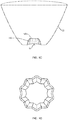
- Figures 9B and 9C depict a light input interface 90 according to some examples, which includes an optical surface 92 disposed about an optical axis (OA), where the surface 92 exhibits a plurality of surface undulations (ripples) 94.
- the optical surface can be characterized as a putative base surface, e.g., a hemispherical surface, on which a plurality of surface undulations are disposed.
- the surface undulations are in the form of a plurality of periodic surface oscillations generating ridges and troughs (such as ridge 96a and trough 96b) that extend from a base 98 of the surface toward a top portion 100 thereof that is free of ridges and troughs.
- the ridges and troughs do not reach the optical axis (OA).
- the top surface portions 100 that is free of ridges and troughs can be a substantially flat surface portion. Alternatively, the top surface portion 100 can be curved.
- the ridges and the troughs can extend from the base 98 of the surface to the apex of the surface, e.g., the intersection of the surface with the optical axis (OA).
- the light input interface 90 can form an input surface of an optic to receive light from a light source.
- the surface 92 provides a cavity through which light from a light source (not shown) can be coupled into an optic (not shown) for which the surface 92 provides an input surface for receiving the light.
- the surface undulations of the light input surface can cause mixing of the light rays as they enter the optic.
- such an optic can include an output surface to receive the light entering the optic via the light input interface, e.g., directly or in some cases via reflection at a peripheral surface, to allow the light to exit the optic.
- Figures 9D and 9E schematically depict another example of a light input interface 102 that includes an optical surface 104 disposed about an optical axis (OA), where the surface exhibits a plurality of surface undulations 106.
- the surface undulations are in the form of a plurality of periodic oscillations that form ridges and troughs, such as illustrated ridge 108a and trough 108b, that extend from a base 110 of the surface to the optical axis (OA).
- the surface 104 has a different putative base profile than the base profile of the surface 92 discussed above.
- the frequency of the surface oscillations in this example is different from the respective frequency of the surface oscillations of the light input interface 90 discussed above.
- the optical surface 104 can provide an input surface of an optic for receiving light from a light source (not shown) and coupling the received light, or at least a portions thereof, into the optic.
- a light input interface can have a variety of base profiles as well as undulation frequencies.
- Figures 9F and 9G depict another light input interface 112 according to the present teachings, which includes an optical surface 114 for receiving light from a light source, where the surface 114 is disposed about an optical axis (OA) and includes a plurality of surface undulations 116.
- the surface undulations extend as a plurality of ridges and troughs (e.g, ridge 118a and trough 118b) from a base 120 to an apex 122, which is the intersection of the surface with the optical axis.
- the base profile of the undulating surface of this light input interface includes a lower concave portion 124 and an upper convex portion 126.
- the optical surface 114 can function as an input surface of an optic for receiving light from a light source (not shown) and coupling the light into the optic.
- FIG. 10 schematically depicts an optic 58 according to another example of the present teachings having a light input interface 60 for receiving light from a light source 62.
- the light input interface 60 provides a cavity for receiving light from a light source.
- the cavity receives the light source, or a portion thereof, while in other examples, the light source is positioned outside the cavity but is optically coupled thereto for delivering at least a portion of its emitted light to the light input interface.
- the light input interface 60 includes a peripheral rippled surface 60a, such as the rippled surfaces discussed above.
- the light input interface 60 further includes a top surface 60b, which is substantially flat.
- the top surface 60b can include a plurality of surface undulations, e.g., microlenses.
- the light input interface can terminate in a point, e.g., similar to the light input interfaces shown in figures 9A , 9D, and 9F discussed above.
- the optic 58 further includes an output surface 64 that is configured to receive the light that enters the lens body via the input interface 60. Such received light that is incident on the output surface 64, or at least a portion thereof, refracts at that surface to exit the lens body.
- the output surface has a dome-like shape.
- the shape of the output surface can be generated by rotation of a parabola about an axis of symmetry, e.g., in this case the optical axis (OA). While in this example the output surface 64 is rotationally symmetric about the optical axis (OA), in other examples, it can be asymmetrie.
- the rippled peripheral surface of the light input interface 60a causes mixing of the light rays incident thereon such that many of these light rays intersect one another in the lens body as they propagate to the output surface 64.
- such mixing of the input light rays can, for example, enhance the uniformity of far-field chromaticity and/or reduce intensity variations, e.g., spikes, in the near-field or far-field intensity profile of the light exiting the lens body through the output surface 64.
- the exiting light can exhibit a chromaticity uniformity in the ranges discussed above.
- the light source 62 can generate light of different colors.
- the light source 62 can include a plurality of light sources (e.g., a plurality of LEDs), each of which generates light of a different color.
- the rippled peripheral surface 60a of the light input interface 60 can cause mixing of the light of different colors such that the far-field chromaticity of the light exiting the output surface exhibits a desired uniformity, such as those discussed above.
- a rippled peripheral surface of a light input interface of an optic can be designed by initially choosing a base curved surface for the peripheral surface and superimposing a plurality of surface undulations on the base curved surface.
- R 0 (z) can be any suitable function, and can be selected based on a variety of considerations, such as, a particular application for which the optic is intended, the intensity distribution of light emitted by a light source coupled to the optic, size limitations, etc.
- R 0 ( z ) can denote a parabola or a portion thereof.
- F(z, ⁇ ) can be selected in a variety of ways.
- it can be an analytical oscillatory function, e.g., a sine or cosine function.
- it can be defined iteratively so as to optimize a merit function, e.g., variation of the far-field chromaticity.
- a merit function e.g., variation of the far-field chromaticity.
- a number of points A1, A2, A3, A4 on the outer circle (C2) and a number of points B1, B2, B3, B4, B5 on the inner circle (C1) can be selected and the surface undulation profile can be constructed by defining each segment connecting one of the point A1 to a respective point B2.
- a spline e.g., a cubic spline
- the cross-sectional undulating profile can then be extended, with appropriate size (and/or phase) scaling, longitudinally along the putative base surface to generate the undulating surface.
- FIG. 13 schematically depicts an optic 66 according to such an example, which includes a light input interface 68 having a rippled peripheral surface 68a and a top surface 68b, an output surface 70 and a peripheral surface 72, which is configured to receive at least a portion of the light entering the lens body via the rippled peripheral surface 68a and redirect that light to the output surface 70 for exiting the optic.
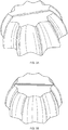
- the peripheral surface 72 is a generally curved surface that includes a plurality of substantially flat portions 74. In other words, the peripheral surface 72 includes alternating curved and flat surface portions.
- the optics according to the present teachings can be manufactured by utilizing a variety of different materials and manufacturing techniques.
- the optics can be formed of a material that is substantially transparent to visible radiation.
- the material from which the optics is formed can exhibit an index of refraction in a range of about 1.4 to about 1.7 in the visible portion of the electromagnetic spectrum.
- suitable materials for forming the optics can include, without limitation, polymethyl methacrylate (PMMA), glass, polycarbonate, cyclic olefin copolymer and cyclic olefin polymer.
- Some suitable manufacturing techniques for fabricating the optics according to the present teachings can include, for example, injection molding and compression molding.
- the optics according to the present teachings can provide the advantages discussed above, such as enhanced uniformity of chromaticity.
- the optics can advantageously ameliorate the tight alignment tolerances that are typically needed between a light source and a conventional optic for obtaining a desired output light distribution.
- the mixing of the light rays by the peripheral surface of the input interface can allow some degree of misalignment between the optic and the light source without significantly degrading a desired distribution (pattern) of the output light.
Landscapes
- Physics & Mathematics (AREA)
- General Physics & Mathematics (AREA)
- Optics & Photonics (AREA)
- Engineering & Computer Science (AREA)
- General Engineering & Computer Science (AREA)
- Planar Illumination Modules (AREA)
Description
- The present patent application generally relates to optics, lenses and lighting systems and methods, and particularly to such optics, lenses and lighting systems and methods for light mixing and/or color mixing.
- Lenses and lighting systems for light sources, such as light emitting diodes, can be utilized in a wide variety of applications. Many lighting applications call for the ability to mix light emitted from a single light source, e.g., to obtain a desired light intensity profile ami/or reduce source imaging. Further, in some applications, it is desirable to mix light emitted from multiple sources, e.g., sources producing light of different colors. It is, however, difficult to produce uniformly mixed light. Many conventional light-mixing systems provide textured surfaces to spread the light from a light source. The efficiency and capabilities of such systems are limited and their illumination characteristics are typically sub-par.
- Accordingly, there is a need for improved light-mixing optics, lenses and respective lighting systems and methods.
US 2011/0051394 A1 discloses an optic having the features recited in the preamble of claim 1. - In one aspect, an optic is disclosed that includes the features recited in claim 1.
- In some embodiments, the light input interface can form a cavity for receiving light from a light source. In some embodiments, the cavity is configured to receive a light source, or a portion thereof. In other embodiments, the light source is disposed outside the cavity with the light entering the cavity.
- In some embodiments, the peripheral surface of the lens body is configured to redirect the light it receives via the rippled surface of the input interface by total internal reflection (TIR). In some embodiments, the peripheral surface of the lens body is configured to redirect such received light by specular reflection (e.g., via reflection from a thin metallic layer disposed on that surface). In some embodiments, the peripheral surface of the lens body is configured to redirect the received light so as to form a substantially collimated light beam exiting the lens body through the output surface. The term "substantially collimated" as used herein refers to a bundle of rays in which the direction of travel of each ray exhibits a deviation equal to or less than 5%, or equal to or less than 3%, relative to the direction of travel of other rays, or relative to a reference direction (e.g., a central ray of the bundle).
- In some embodiments, the rippled surface of the light input interface comprises a plurality of periodic surface oscillations. In some such embodiments, the surface oscillations exhibit a uniform oscillation amplitude while in some other such embodiments, the surface oscillations exhibit a non-uniform amplitude. In some embodiments, an oscillation amplitude of the surface oscillations can be in a range of about 10 micrometers (microns) to about 1 millimeter (mm). The surface oscillations can exhibit a variety of different frequencies. In some embodiments, the surface oscillations can exhibit a frequency in a range of about 5/π to about 180/π (radian)-1.
- In some embodiments, the rippled surface forms a peripheral surface of the light input interface and the light input interface can further include a top surface adapted to receive a portion of the light generated by the light source and to direct the received light to the output surface of the optic for exiting the lens body. In some embodiments, the top surface of the input interface is substantially flat while in other embodiments it can be a curved surface. In some embodiments, the top surface of the input interface can include a plurality of surface undulations, such as microlenses. Such surface undulations can be employed, e.g., to mix the light rays that are incident on the top surface via the light source and enter the lens body via refraction at that surface. For example, many of such light rays can intersect within the lens body as they propagate from the top surface of the input interface to the output surface of the lens body. In some other embodiments, the rippled surface of the light input interface extends from a base of the surface to a top surface portion thereof that is free of surface undulations. In some embodiments, the rippled surface of the light input interface extends from a base of the surface to an apex thereof.
- In some embodiments, a ratio of a length of the peripheral surface of the input interface along a reference longitudinal axis (e.g., an optical axis of the optic) relative to a respective length of the optic can be in a range of about 0.1 to about 1.
- Further understanding of various aspects of the invention can be obtained by reference to the following detailed description and the associated drawings, which are described briefly below.
-
-
FIG. 1A is a schematic view of an optic according to an example having a light input interface according to the present teachings, -
FIG. 1B is a schematic perspective top view of the light input interface of the optic depicted inFIG. 1A , -
FIG. 1C is a schematic cross-sectional view of the optic ofFIG. 1A receiving light from a light source via its light input interface, -
FIG. 1D is a schematic perspective top view of the light input interface of the optic ofFIG. 1A . -
FIG. 1E is another schematic perspective view of the light input interface of the optic ofFIG. 1A , -
FIG 2A schematically depicts a cross-section of the rippled peripheral surface of the light input interface of the optic ofFIG. 1A in a surface perpendicular to the optical axis, -
FIG. 2B schematically depicts a cross-sectional view of a light input interface according to another example exhibiting a plurality of surface oscillations with a non-uniform amplitude, -
FIG. 3A schematically depicts a light input interface according to an example, -
FIG. 3B schematically depicts a light input interface according to any example, -
FIG. 3C schematically depicts a light input interface according to an example, -
FIG. 4A is a top schematic view of a rippled surface of a light input interface according to an example, -
FIG. 4B is a top schematic view of a rippled surface of a light input interface according to an example, -
FIG. 5 is a schematic partial side view of an example of a light mixing system, -
FIG. 6 schematically depicts a conventional lens receiving light from a light source, -
FIG. 7A schematically depicts a light input interface according to an example, having a top surface comprising a plurality of surface undulations, -
FIG. 7B schematically depicts a light mixing system according to an example. -
FIG. 7C schematically depicts a light input interface of the light mixing system ofFIG. 7B , wherein the light input interface includes a plurality of microlenses on a top surface thereof, -
FIG. 7D is a top view of the light input interface depicts inFIG. 7C , -
FIG. 8 schematically depicts a light input interface according to an embodiment of the teachings of the invention, -
FIG. 9A schematically depicts an optic according to an example, -
FIG. 9B is a schematic perspective view of a light input interface according to an example, -
FIG. 9C is a schematic top view of the light input interface ofFIG. 9B , -
FIG. 9D is a schematic perspective view of a light input interface according to an example, -
FIG. 9E is a schematic top view of the light input interface ofFIG. 9D , -
FIG. 9F is a schematic perspective view of a light input interface according to an example, -
FIG. 9G is schematic top view of the light input interface ofFIG. 9F , -
FIG. 10 schematically depicts an optic according to an example, -
FIG. 11 shows radial and angular variables for mathematically defining a rippled surface of a light input interface in accordance with some examples -
FIG. 12 shows radial constraints employed in a method for designing a rippled surface of a light input interface, and -
FIG. 13 schematically depicts an optic according to an example. -
FIGS. 1A - 1E schematically depict an optic 10 according to an example that comprises alens body 12 disposed about an optical axis (OA), where the optic includes alight input interface 14 adapted to receive light from a light source, such as the illustrativelight source 16 schematically shown inFIG. 1C . In this illustrated example the input interface forms a cavity for receiving the light emitted by thelight source 16. In some examples the cavity can be configured to receive the light source itself, or at least a portion thereof. In other examples the light source is located external to the cavity, but optically coupled to the cavity such that the cavity receives at least a portion of the light emitted by the source. As discussed in more detail below, in this illustrative example thelight input interface 14 includes a rippledperipheral surface 14a and atop surface 14b. - The light received by the input interface, or at least a portion thereof, enters the lens body through the surfaces of the input interface, e.g., via refraction at those surfaces. The optic 10 also includes an
output surface 18 through which the light can exit the lens body, and aperipheral surface 20 that is configured to receive at least a portion of the light entering the lens body via thelight input interface 14 and to redirect that light, or at least a portion thereof, to theoutput surface 18 for exiting the lens body. In this illustrative example the peripheral surface is configured to redirect the light it receives from the light input interface to theoutput surface 18 via total internal reflection (TIR). In other examples, the peripheral surface can be configured to redirect the light incident thereon to theoutput surface 18 via specular reflection. For example, in some such examples, a thin metallic layer can be disposed on the peripheral surface, or at least a portion thereof, to cause specular reflection of the incident light. - The rippled
peripheral surface 14a of thelight input interface 14 includes a plurality of surface undulations (See, e.g., FIG. IB). Tin particular, in this illustrative example, the surface undulations of the rippledperipheral surface 14a can be characterized by a plurality ofridges 22 and valleys (troughs) 24. In other words, the undulations of then rippledperipheral surface 14a of the input interface can be characterized as variations of the orthogonal distances of various points on that surface relative to the optical axis (OA). An orthogonal distance as used herein refers to the length of a line segment that connects a surface point to the optical axis (OA) in a plane that is orthogonal to the optical axis, e.g., distance D shown inFIG. 1B . For example, as shown inFIG. 1B , the surface points along the ridges are farthest away from the optical axis and the points long the valleys are the closest to the optical surface with the distances of other surface points varying between these two extremes. - In some examples, the surface undulations are in the form of periodic surface oscillations. For example, with reference to FIG. IB, in this example, the surface undulations comprise a surface oscillation (SO) that is repeated 10 times in a 2π radian rotation about the optical axis (OA). In other words, the frequency of the surface oscillations in this example is 10/2π (radian) other oscillation frequencies can also be employed. By way of example, in some examples, the frequency of the surface oscillations can be in a range of 5/π to about 180/π (radian)-1.
- The surface undulations can have uniform or non-uniform amplitudes. An amplitude of a surface oscillation as used herein refers to the distance between a peak and an adjacent valley of a surface oscillation. For example,
FIG. 2A depicts a cross-section of the rippledperipheral surface 14a perpendicular to the optical axis (OA), which illustrates a cross-sectional view of the surface oscillations.FIG. 2A shows that in this illustrative example, the surface oscillations can be characterized by a uniform oscillation amplitude (A). In some other examples, however, the oscillation amplitude(s) of the surface undulations can be non-uniform. For example,FIG. 2B schematically depicts a cross-sectional view of the rippled peripheral surface of a light input interface according to another example, which comprises a plurality of repeating surface oscillations (SO), where the surface oscillations are characterized by a non-uniform amplitude. For example, in this example, each surface oscillation can be characterized by two peak-to-valley distances A1 and A2, each measured between a peak and an adjacent valley of the surface. - By way of illustration,
FIGURES 3A-3C schematically illustrate examples of a light input interface according to the present teachings, which exhibit different oscillation frequencies and oscillations amplitudes. Further, these exemplary light input interlaces illustrate that a variety of different surface profiles can be employed to implement the surface oscillations. By way of example, in some examples, the surface profile can comprise a plurality of flat surface portions, where each two adjacent surface portions are tilted relative to one another and intersect along a ridge (FIG. 4A schematically depicts a cross-sectional view of such an example). In other examples, the surface profile can include a plurality of curved surface portions. By way of example, the cross-sectional profile of the surface oscillations can be characterized as a harmonic or non-harmonic oscillation. For example, the cross-section of the surfaces oscillations in a plane perpendicular to the optical axis (OA) can be characterized by a plurality of sinusoidal oscillations. - By way of further example, the surface profile can comprise a circular cross-suction having a radius R1 and a plurality of semi-circular recesses having a radius R2 formed about the periphery thereof (
FIG. 4B schematically depicts a cross-sectional view of such an example). The R1 and R2 can be selected to provide a ratio R1/R2 having any of a variety of values, e.g., in a range of about 9 to about 100. While in this example, the center of each of the semi-circular recesses having a radius R2 is on a circle defined by the radius R1, in other examples, the centers of one or more of the semi-circular recesses having a radius R2 can be offset relative to a circle defined by the radius R1. - Referring again to
FIG. 1B , in use, at least a portion of the light rays emitted by thelight source 16 is incident on the peripheral rippledsurface 14a of theinput interface 14. The incident light rays refract at the rippledperipheral surface 14a to enter thelens body 12. The undulations of the rippled peripheral surface cause the mixing of the light rays as they enter the lens body through that surface. In other words, a number of rays incident on the rippled peripheral surface refract at the surface undulations such that they intersect in the lens body as they propagate toward theperipheral surface 20 of the optic. By way of illustration, light rays A and B emitted from thelight source 16 diverge as they propagate from the light source to the peripheral rippledsurface 14a. These light rays enter the lens body via refraction at the rippled peripheral surface of the input interface such that they intersect at point (P) and then diverge again as they propagate toward theperipheral surface 20 of the optic. Such mixing of the light rays mediated by the peripheral rippled surface of the light input interface can advantageously enhance the uniformity of the light beam exiting the optic via theoutput surface 18. For example, in some examples, the mixing of the light by the input interface can reduce, and preferably eliminate, deviations between a desired light intensity profile and the light intensity profile obtained by using the optic. - In some examples, the light uniformity can refer to the degree of the uniformity of far-field chromaticity of the light beam when the light entering the input interface can comprise a plurality of different colors. Alternatively or addition, the uniformity of the light can refer to a variation of the light intensity over cross-sectional area of the exiting beam, e.g., when one or more monochromatic light sources are employed. Further, the terms "near field" and "far field" are known in the art. To the extent that any further explanation might be needed, the term "near field*' refers to a region whose maximum distance from the output surface of the lens is less than a threshold, e.g., equal to or less than a diameter (OD) of the output surface. The term "far field" refers to a region whose minimum distance from the output surface is significantly greater than a threshold, e.g., at least about 10, or at least about 20, or at least about 100 times greater than a diameter (OD) of the output surface. The near-field and the far-field regions can be separated by a transition region. By way of example, for an optic with an output surface having a diameter of 20 mm, the far field can extend from a distance of 200 mm from the output surface to infinity, and the near field can extend from the output surface to a distance of about 200 mm from the output surface.
- In some examples, an optic according to the present teachings, such as the
exemplary optic 10, can be used to mix light from a plurality of light sources emitting light of different colors. By way of example,FIG. 5 schematically depicts alight mixing system 26 according to the present teachings that includes twolight sources light input interface 14 causes mixing of the light from these two sources, and hence mixing of the colors, in a manner described above. In some examples, the mixing of the light of different colors by the optic 10 can reduce, and preferably eliminate, spatial variations in the far-field chromaticity associated with the output beam. - As known in the art, chromaticity can provide an objective measure of color regardless of luminance. For example, in C1ELUV chromaticity, the color can be defined by two coordinates (U, V) such that each point in a color space spanned by the axes U and V corresponds to a distinct color (chromaticity). In some examples, the
system 26 can provide a substantially uniform far-field chromaticity. For example, the variation of CIELUV chromaticity across a far-field plane perpendicular to the propagation axis of a beam exiting the optic 10 can be less than about 0.001. - In some examples, the optic 10 can be employed to mix the light from a monochromatic light source so as to obtain a near-field and/or far-field light intensity profile that substantially matches a desired intensity profile . For example, the mixing of the light by the optic can reduce, and in some cases, eliminate high frequency variations, e.g., spikes, in the far-field light intensity profile that could otherwise arise in absence of the light mixing.
- In contrast, a
conventional lens 30, shown inFIG. 6 , having a light input interface with a peripheral surface lacking surface undulations, does not cause mixing of the light rays entering the lens body through that peripheral surface. For example, the diverging light rays emitted by alight source 32 enter the lens body via refraction at the peripheral surface and propagate to the peripheral surface of the lens without intersecting one another within the lens body. - Referring again to
FIG. 1A , the optic 10 can have a variety of dimensions. In some embodiments, the optic 10 can have a length (LO) along the optical axis that is less than about 100 mm, e.g., in a range of about 10 mm to about 100 mm. The length of the optic can be defined as the extension of the optic along the optical axis (OA) from a proximal end (PE) to a distal end (DE). For example, with reference toFIG. 1A , the length of the optic 10 is herein defined as the distance along the optical axis (OA) between the intersection of the optical axis with theoutput surface 18 of the optic 10 (i.e., point A) and the intersection of the optical axis (OA) with a putative surface (S) containing the proximal points of the optic 10 (i.e., point B in this example). Further, in some examples, thelight input interface 14 can have a length (LI) in a range of about 1 mm to about 100 mm, for example, about 3 mm in this example. The length of theinput interface 14 is herein defined as the distance along the optical axis between the intersection of the optical axis (OA) with thetop surface 14b of the input interface and the point (B). Thus, in some examples, a compact optic can be provided that can cause effective mixing of the input light, e.g., to achieve desired near-field and far-field light intensity profile(s) and/or uniform chromaticity. -
FIGS. 7A-7D schematically show that in some examples, thetop surface 14b of the light input interface of an optic according to the present teachings can include a plurality ofsurface undulations 42 for mixing the light incident thereon from one or more light sources. In this illustrative example, these surface undulations are in the form of a plurality of lenses, e.g., microlenses, disposed on thetop surface 14b of theinput interface 14. For example,FIG. 7B schematically depicts alight mixing system 34 according to an example that includes an optic 36 and alight source 38 that comprises four LEDs (38a, 38b, 38c, and 38d). Similar to the previous examples, the optic 36 includes alight input interface 40 having a rippledperipheral surface 40a that includes a plurality of surface undulations. In this example, atop surface 40b of the input interface includes a plurality ofmicrolenses 42 that cause mixing of the light incident on thetop surface 40b from the LEDs as they enter the lens body via refraction at that surface and propagate to anoutput surface 44 of the optic for exiting the optic. Such mixing of the light by themicrolenses 42 can have a number of advantages. For example, it can reduce, or preferably eliminate, dark bands that could otherwise arise, in some cases, in the far-field illumination pattern due to separation of the LEDs from one another. - In some example, the surface undulations of the peripheral surface of the input interface can comprise a plurality of surface oscillations, where the surface oscillations in one cross-sectional plane have a phase offset relative to the surface oscillations in an adjacent cross-sectional plane. In this manner, a plurality of longitudinally curved ridges and valleys can be provided. For example,
FIG. 8 schematically depicts an example of an optic 48 according to such an embodiment in which aninput interface 50 includesridges 50a andvalleys 50b that are curved along the longitudinal axis of the optic (OA). In some examples, theridges 50a and thevalleys 50b exhibit oscillations along the longitudinal axis. -
FIG. 9A schematically depicts an optic 52 according to another example of the present teachings, which similar to the previous examples includes alight input interface 54, anoutput surface 56, and aperipheral surface 58 for redirecting light received from the input interface to the output surface. Similar to the previous examples, thelight input interface 54 includes a rippledperipheral surface 54a. In this example, however, the rippledperipheral surface 54a of the input interface extends to apoint 54b, rather than a top surface similar to thesurface 14b of theabove optic 10. For example, in some examples, the rippledperipheral surface 54a can be characterized as a putative three-dimensional parabolic surface on which a plurality of surface undulations are superimposed, where the top point of the input interface corresponds to the apex of the parabolic surface. - By way of further illustration,
Figures 9B and 9C depict alight input interface 90 according to some examples, which includes anoptical surface 92 disposed about an optical axis (OA), where thesurface 92 exhibits a plurality of surface undulations (ripples) 94. The optical surface can be characterized as a putative base surface, e.g., a hemispherical surface, on which a plurality of surface undulations are disposed. In this example, the surface undulations are in the form of a plurality of periodic surface oscillations generating ridges and troughs (such asridge 96a andtrough 96b) that extend from abase 98 of the surface toward atop portion 100 thereof that is free of ridges and troughs. In this example, the ridges and troughs do not reach the optical axis (OA). In some examples, thetop surface portions 100 that is free of ridges and troughs can be a substantially flat surface portion. Alternatively, thetop surface portion 100 can be curved. In other implementations, the ridges and the troughs can extend from thebase 98 of the surface to the apex of the surface, e.g., the intersection of the surface with the optical axis (OA). Similar to the previous examples, thelight input interface 90 can form an input surface of an optic to receive light from a light source. Specifically, thesurface 92 provides a cavity through which light from a light source (not shown) can be coupled into an optic (not shown) for which thesurface 92 provides an input surface for receiving the light. The surface undulations of the light input surface can cause mixing of the light rays as they enter the optic. Similar to theabove optic 10, such an optic can include an output surface to receive the light entering the optic via the light input interface, e.g., directly or in some cases via reflection at a peripheral surface, to allow the light to exit the optic. -
Figures 9D and 9E schematically depict another example of alight input interface 102 that includes anoptical surface 104 disposed about an optical axis (OA), where the surface exhibits a plurality ofsurface undulations 106. In this example, the surface undulations are in the form of a plurality of periodic oscillations that form ridges and troughs, such as illustratedridge 108a andtrough 108b, that extend from abase 110 of the surface to the optical axis (OA). Thesurface 104 has a different putative base profile than the base profile of thesurface 92 discussed above. Further, the frequency of the surface oscillations in this example is different from the respective frequency of the surface oscillations of thelight input interface 90 discussed above. Similar to the previous examples, theoptical surface 104 can provide an input surface of an optic for receiving light from a light source (not shown) and coupling the received light, or at least a portions thereof, into the optic. - As discussed above, a light input interface according to the present teachings can have a variety of base profiles as well as undulation frequencies. By way of another example,
Figures 9F and 9G depict anotherlight input interface 112 according to the present teachings, which includes anoptical surface 114 for receiving light from a light source, where thesurface 114 is disposed about an optical axis (OA) and includes a plurality ofsurface undulations 116. The surface undulations extend as a plurality of ridges and troughs (e.g,ridge 118a andtrough 118b) from a base 120 to an apex 122, which is the intersection of the surface with the optical axis. The base profile of the undulating surface of this light input interface includes a lowerconcave portion 124 and an upperconvex portion 126. Again, similar to the previous examples, theoptical surface 114 can function as an input surface of an optic for receiving light from a light source (not shown) and coupling the light into the optic. -
FIG. 10 schematically depicts an optic 58 according to another example of the present teachings having alight input interface 60 for receiving light from alight source 62. In particular, in this example, thelight input interface 60 provides a cavity for receiving light from a light source. In some examples, the cavity receives the light source, or a portion thereof, while in other examples, the light source is positioned outside the cavity but is optically coupled thereto for delivering at least a portion of its emitted light to the light input interface. Similar to the previous examples, thelight input interface 60 includes a peripheral rippledsurface 60a, such as the rippled surfaces discussed above. In this embodiment, thelight input interface 60 further includes atop surface 60b, which is substantially flat. In other examples, thetop surface 60b can include a plurality of surface undulations, e.g., microlenses. Further, in some examples, rather than having a top surface, the light input interface can terminate in a point, e.g., similar to the light input interfaces shown infigures 9A ,9D, and 9F discussed above. - The optic 58 further includes an
output surface 64 that is configured to receive the light that enters the lens body via theinput interface 60. Such received light that is incident on theoutput surface 64, or at least a portion thereof, refracts at that surface to exit the lens body. In this example, the output surface has a dome-like shape. For example, the shape of the output surface can be generated by rotation of a parabola about an axis of symmetry, e.g., in this case the optical axis (OA). While in this example theoutput surface 64 is rotationally symmetric about the optical axis (OA), in other examples, it can be asymmetrie. - Similar to the precious examples, the rippled peripheral surface of the
light input interface 60a causes mixing of the light rays incident thereon such that many of these light rays intersect one another in the lens body as they propagate to theoutput surface 64. In some examples, such mixing of the input light rays can, for example, enhance the uniformity of far-field chromaticity and/or reduce intensity variations, e.g., spikes, in the near-field or far-field intensity profile of the light exiting the lens body through theoutput surface 64. For example, the exiting light can exhibit a chromaticity uniformity in the ranges discussed above. - In some examples, the
light source 62 can generate light of different colors. For example, in some examples, thelight source 62 can include a plurality of light sources (e.g., a plurality of LEDs), each of which generates light of a different color. In such examples, the rippledperipheral surface 60a of thelight input interface 60 can cause mixing of the light of different colors such that the far-field chromaticity of the light exiting the output surface exhibits a desired uniformity, such as those discussed above. - In some examples, a rippled peripheral surface of a light input interface of an optic according to the present teachings can be designed by initially choosing a base curved surface for the peripheral surface and superimposing a plurality of surface undulations on the base curved surface. By way of example, a surface profile of the rippled peripheral surface of the light input interface can be defined by the following relation:

FIG. 11 , - r(z, θ) denotes the radial position of the undulating surface from a reference axis (e.g., central axis (OA)) as a function of longitudinal distance (z) along that axis (A) and azimuthal angle (θ),
- R0(z) denotes radial positions of a putative base curved surface from the reference axis as a function of longitudinal distance (z) along that axis,
- F(z, θ) denotes undulations superimposed on the base curved surface as a function of distance (z) along the reference axis (A) and azimuthal angle (θ) around that axis. In many embodiments, F(z,θ) is periodic in variable (θ).
- R0(z) can be any suitable function, and can be selected based on a variety of considerations, such as, a particular application for which the optic is intended, the intensity distribution of light emitted by a light source coupled to the optic, size limitations, etc. For example, in some embodiments, R0(z) can denote a parabola or a portion thereof.
- Further, F(z, θ) can be selected in a variety of ways. For example, in some embodiments, it can be an analytical oscillatory function, e.g., a sine or cosine function. In some embodiments, it can be defined iteratively so as to optimize a merit function, e.g., variation of the far-field chromaticity. By way of example, with reference to
FIG. 12 , in a given cross-sectional plane orthogonal to the central axis (OA), the amplitude of the surface undulations can be confined between two putative circles (C1) and (C2). A number of points A1, A2, A3, A4 on the outer circle (C2) and a number of points B1, B2, B3, B4, B5 on the inner circle (C1) can be selected and the surface undulation profile can be constructed by defining each segment connecting one of the point A1 to a respective point B2. In some cases, a spline, e.g., a cubic spline, can be employed to interpolate between these points to generate the cross-sectional undulating profile. The cross-sectional undulating profile can then be extended, with appropriate size (and/or phase) scaling, longitudinally along the putative base surface to generate the undulating surface. - In some examples, the peripheral surface of an optic according to the present teachings, which is configured to redirect light received from the input interface to the output surface of the optic, can be fluted. By way of example,
FIG. 13 schematically depicts an optic 66 according to such an example, which includes alight input interface 68 having a rippledperipheral surface 68a and atop surface 68b, anoutput surface 70 and aperipheral surface 72, which is configured to receive at least a portion of the light entering the lens body via the rippledperipheral surface 68a and redirect that light to theoutput surface 70 for exiting the optic. In this example, theperipheral surface 72 is a generally curved surface that includes a plurality of substantiallyflat portions 74. In other words, theperipheral surface 72 includes alternating curved and flat surface portions. - The optics according to the present teachings can be manufactured by utilizing a variety of different materials and manufacturing techniques. Generally, the optics can be formed of a material that is substantially transparent to visible radiation. In some embodiments, the material from which the optics is formed can exhibit an index of refraction in a range of about 1.4 to about 1.7 in the visible portion of the electromagnetic spectrum. Some suitable materials for forming the optics can include, without limitation, polymethyl methacrylate (PMMA), glass, polycarbonate, cyclic olefin copolymer and cyclic olefin polymer.
- Some suitable manufacturing techniques for fabricating the optics according to the present teachings can include, for example, injection molding and compression molding.
- The optics according to the present teachings can provide the advantages discussed above, such as enhanced uniformity of chromaticity. In addition, in some embodiments, the optics can advantageously ameliorate the tight alignment tolerances that are typically needed between a light source and a conventional optic for obtaining a desired output light distribution. In particular, in some embodiments, the mixing of the light rays by the peripheral surface of the input interface can allow some degree of misalignment between the optic and the light source without significantly degrading a desired distribution (pattern) of the output light.
- Those having ordinary skill in the art will appreciate that various changes can be made to the above embodiments without departing from the scope of the invention.
Claims (19)
- An optic (10) having a longitudinal axis (OA), comprising
a lens body (12), comprising
a light input interface (14, 50) configured to receive light generated by a light source, said light input interface having a rippled surface (14a, 50a, 50b) through which at least a portion of the received light enters the lens body (12),
an output surface (18) through which light exits the lens body (12), and
a peripheral surface (20) configured to receive at least a portion of the light entering the lens body (18) via said rippled surface (14a) and to redirect at least a portion of said received light to the output surface (18) for exiting the lens body (12)
characterized in that
said light input interface (14, 50) includes ridges (50a) and valleys (50b) that are curved along the longitudinal axis (OA) of the optic. - The optic of claim 1, wherein said peripheral surface (20) of the optic (10) is configured to redirect the received light via total internal reflection or via specular reflection.
- The optic of claim 1, wherein said peripheral surface (20) of the optic (10) is configured to redirect the received light so as to form a substantially collimated light beam for exiting the lens body (12) through said output surface (18).
- The optic of claim 1, wherein said peripheral surface (20) of the optic (10) comprises a plurality of flat and a plurality of curved surface portions.
- The optic of claim 1, wherein said rippled surface (14a) of the light input interface (14, 50) comprises a plurality of periodic surface oscillations, said periodic surface oscillations of the rippled surface exhibit a uniform oscillation amplitude, or a non-uniform amplitude.
- The optic of claim 5, wherein said periodic surface oscillations exhibit an oscillation amplitude of at least about 10 microns.
- The optic of claim 5, wherein said periodic surface oscillations exhibit an oscillation frequency in a range of about 5/π to about 180/π (radian)-1.
- The optic of claim 1, wherein said rippled surface (14a) forms a peripheral surface of said light input interface (14, 50).
- The optic of claim 8, wherein said light input interface (14, 50) further comprises a top surface (14b) adapted to receive a portion of the light generated by the light source and to direct at least part of said received light into the lens body (12).
- The optic of claim 9, wherein said top surface (14b) of the light input interface (14, 50) is substantially flat, or curved.
- The optic of claim 9, wherein said top surface (14b) of the light input interface (14, 50) comprises a plurality of surface undulations.
- The optic of claim 11, wherein said surface undulations of the top surface (14b) of the light input interface comprise a plurality of microlenses.
- The optic of claim 1, wherein said rippled surface (14a) of the light input interface (14, 50) extends from a base of the surface to a top surface portion of the cavity that is free of surface undulations.
- The optic of claim 1, wherein said rippled surface (14a) of the light input interface extends from a base of the surface to an apex thereof.
- The optic of claim 1, wherein said longitudinal axis (OA) is an optical axis.
- The optic of claim 15, wherein a ratio of a length of said cavity along said optical axis relative to a length of said lens body (12) along said optical axis is in a range of about 0.1 about 1.
- The optic of claim 1, wherein said lens body (12) is a solid lens body.
- The optic of claim 1, wherein said rippled surface (14a) is configured such that a plurality of light rays of the received light intersect within the lens body (12).
- The optic of claim 5, wherein said periodic surface oscillations exhibit an oscillation amplitude in a range of about 10 microns to about 1 mm.
Applications Claiming Priority (2)
| Application Number | Priority Date | Filing Date | Title |
|---|---|---|---|
| US201261607134P | 2012-03-06 | 2012-03-06 | |
| PCT/US2013/029342 WO2013134369A1 (en) | 2012-03-06 | 2013-03-06 | Oscillating interface for light mixing lenses |
Publications (2)
| Publication Number | Publication Date |
|---|---|
| EP2823346A1 EP2823346A1 (en) | 2015-01-14 |
| EP2823346B1 true EP2823346B1 (en) | 2017-06-14 |
Family
ID=47989368
Family Applications (1)
| Application Number | Title | Priority Date | Filing Date |
|---|---|---|---|
| EP13711780.0A Not-in-force EP2823346B1 (en) | 2012-03-06 | 2013-03-06 | Oscillating interface for light mixing lenses |
Country Status (3)
| Country | Link |
|---|---|
| US (1) | US9255688B2 (en) |
| EP (1) | EP2823346B1 (en) |
| WO (1) | WO2013134369A1 (en) |
Cited By (1)
| Publication number | Priority date | Publication date | Assignee | Title |
|---|---|---|---|---|
| AT524838B1 (en) * | 2021-06-17 | 2022-10-15 | Optronia Gmbh | total internal reflection lens |
Families Citing this family (22)
| Publication number | Priority date | Publication date | Assignee | Title |
|---|---|---|---|---|
| JP6111110B2 (en) * | 2012-08-27 | 2017-04-05 | 株式会社エンプラス | Luminous flux control member, light emitting device, surface light source device, and display device |
| US9565782B2 (en) | 2013-02-15 | 2017-02-07 | Ecosense Lighting Inc. | Field replaceable power supply cartridge |
| JP2015212792A (en) * | 2014-05-07 | 2015-11-26 | 株式会社エンプラス | Luminous flux control member, light emitting device, surface light source device, and display device |
| US10477636B1 (en) | 2014-10-28 | 2019-11-12 | Ecosense Lighting Inc. | Lighting systems having multiple light sources |
| CN105627250A (en) * | 2014-11-05 | 2016-06-01 | 东莞雷笛克光学有限公司 | Optical component and lighting device having said optical component |
| US11306897B2 (en) | 2015-02-09 | 2022-04-19 | Ecosense Lighting Inc. | Lighting systems generating partially-collimated light emissions |
| US9869450B2 (en) | 2015-02-09 | 2018-01-16 | Ecosense Lighting Inc. | Lighting systems having a truncated parabolic- or hyperbolic-conical light reflector, or a total internal reflection lens; and having another light reflector |
| CN104633594B (en) * | 2015-02-17 | 2018-05-15 | 宁波石上光电科技有限公司 | A kind of light-distribution lens for power type LED lamp |
| US9746159B1 (en) | 2015-03-03 | 2017-08-29 | Ecosense Lighting Inc. | Lighting system having a sealing system |
| US9651216B2 (en) | 2015-03-03 | 2017-05-16 | Ecosense Lighting Inc. | Lighting systems including asymmetric lens modules for selectable light distribution |
| US9568665B2 (en) | 2015-03-03 | 2017-02-14 | Ecosense Lighting Inc. | Lighting systems including lens modules for selectable light distribution |
| US9651227B2 (en) | 2015-03-03 | 2017-05-16 | Ecosense Lighting Inc. | Low-profile lighting system having pivotable lighting enclosure |
| CN205244911U (en) * | 2015-03-12 | 2016-05-18 | 浚洸光学科技股份有限公司 | Lighting device and optical member thereof |
| CN104712936A (en) * | 2015-03-18 | 2015-06-17 | 四川联恺环保科技有限公司 | LED spotlight |
| USD785218S1 (en) | 2015-07-06 | 2017-04-25 | Ecosense Lighting Inc. | LED luminaire having a mounting system |
| USD782094S1 (en) | 2015-07-20 | 2017-03-21 | Ecosense Lighting Inc. | LED luminaire having a mounting system |
| USD782093S1 (en) | 2015-07-20 | 2017-03-21 | Ecosense Lighting Inc. | LED luminaire having a mounting system |
| US9651232B1 (en) | 2015-08-03 | 2017-05-16 | Ecosense Lighting Inc. | Lighting system having a mounting device |
| US10261232B2 (en) * | 2015-08-10 | 2019-04-16 | Ecosense Lighting Inc. | Optical devices and systems having a converging lens with an input cavity having grooves following a spline and a frusto-conical reflection side surface extending between an input and output surface of the converging lens |
| CN106568068A (en) * | 2015-10-09 | 2017-04-19 | 瑞仪光电(苏州)有限公司 | Light guiding lens and light source module |
| EP4241015A1 (en) * | 2020-11-06 | 2023-09-13 | Signify Holding B.V. | Total internal reflection lens |
| AT525511A1 (en) * | 2021-09-23 | 2023-04-15 | Optronia Gmbh | Method for identifying at least one object |
Citations (1)
| Publication number | Priority date | Publication date | Assignee | Title |
|---|---|---|---|---|
| US20110051394A1 (en) * | 2007-09-10 | 2011-03-03 | Lighting Science Group Corp. | Warm white lighting device |
Family Cites Families (9)
| Publication number | Priority date | Publication date | Assignee | Title |
|---|---|---|---|---|
| DE19728354C2 (en) * | 1997-07-03 | 1999-12-02 | Sidler Gmbh & Co | Refractor element as an attachment for a light source and use of such a refractor element as an attachment for a brake light of a vehicle |
| JP2004259541A (en) * | 2003-02-25 | 2004-09-16 | Cateye Co Ltd | lighting equipment |
| US7006306B2 (en) * | 2003-07-29 | 2006-02-28 | Light Prescriptions Innovators, Llc | Circumferentially emitting luminaires and lens-elements formed by transverse-axis profile-sweeps |
| CA2493828C (en) * | 2004-01-23 | 2012-01-10 | Genlyte Thomas Group Llc | Full cutoff area light fixture |
| US6989340B2 (en) * | 2004-05-11 | 2006-01-24 | Tokan Material Technology Co., Ltd. | Lead-free low softening point glass |
| TWI249257B (en) * | 2004-09-24 | 2006-02-11 | Epistar Corp | Illumination apparatus |
| US7777955B2 (en) | 2005-07-29 | 2010-08-17 | Optical Research Associates | Rippled mixers for uniformity and color mixing |
| JP5540018B2 (en) * | 2009-02-03 | 2014-07-02 | フレーン・コーポレーシヨン | Light mixing optical device and light mixing system |
| DE102011015405A1 (en) * | 2011-03-29 | 2012-10-04 | Osram Opto Semiconductors Gmbh | Optical element and radiation-emitting device with such an optical element |
-
2013
- 2013-03-06 WO PCT/US2013/029342 patent/WO2013134369A1/en not_active Ceased
- 2013-03-06 EP EP13711780.0A patent/EP2823346B1/en not_active Not-in-force
- 2013-03-06 US US13/787,148 patent/US9255688B2/en active Active
Patent Citations (1)
| Publication number | Priority date | Publication date | Assignee | Title |
|---|---|---|---|---|
| US20110051394A1 (en) * | 2007-09-10 | 2011-03-03 | Lighting Science Group Corp. | Warm white lighting device |
Cited By (2)
| Publication number | Priority date | Publication date | Assignee | Title |
|---|---|---|---|---|
| AT524838B1 (en) * | 2021-06-17 | 2022-10-15 | Optronia Gmbh | total internal reflection lens |
| AT524838A4 (en) * | 2021-06-17 | 2022-10-15 | Optronia Gmbh | total internal reflection lens |
Also Published As
| Publication number | Publication date |
|---|---|
| WO2013134369A1 (en) | 2013-09-12 |
| EP2823346A1 (en) | 2015-01-14 |
| US20130265777A1 (en) | 2013-10-10 |
| US9255688B2 (en) | 2016-02-09 |
Similar Documents
| Publication | Publication Date | Title |
|---|---|---|
| US9255688B2 (en) | Oscillating interface for light mixing lenses | |
| US9890926B2 (en) | Low profile multi-lens TIR | |
| EP2846179B1 (en) | Light mixing optics and systems | |
| EP2497996B1 (en) | Lighting device | |
| US10663651B2 (en) | Light mixing systems with a glass light pipe | |
| EP2917636B1 (en) | Multi-led/multi-chip color mixing optics | |
| EP3299707B1 (en) | Light mixing lenses and systems | |
| US9442241B2 (en) | Optics for illumination devices | |
| US10663652B2 (en) | Light mixing systems with a glass light pipe | |
| US20190033511A1 (en) | Light Mixing Systems With A Glass Light Pipe And A Light-Shaping Element | |
| EP2823216B1 (en) | Light emitting panel assemblies and light guides therefor | |
| US20190094443A1 (en) | Multi-LED/Multi-Chip Color Mixing Optics | |
| EP3311216B1 (en) | Light mixing systems with a glass light pipe | |
| CN108692294B (en) | Special-shaped lens |
Legal Events
| Date | Code | Title | Description |
|---|---|---|---|
| PUAI | Public reference made under article 153(3) epc to a published international application that has entered the european phase |
Free format text: ORIGINAL CODE: 0009012 |
|
| 17P | Request for examination filed |
Effective date: 20141003 |
|
| AK | Designated contracting states |
Kind code of ref document: A1 Designated state(s): AL AT BE BG CH CY CZ DE DK EE ES FI FR GB GR HR HU IE IS IT LI LT LU LV MC MK MT NL NO PL PT RO RS SE SI SK SM TR |
|
| AX | Request for extension of the european patent |
Extension state: BA ME |
|
| DAX | Request for extension of the european patent (deleted) | ||
| RIN1 | Information on inventor provided before grant (corrected) |
Inventor name: HOUSAND, BRIEN Inventor name: PRESTON, JAMES Inventor name: ZOLLERS, MICHAEL |
|
| REG | Reference to a national code |
Ref country code: DE Ref legal event code: R079 Ref document number: 602013022217 Country of ref document: DE Free format text: PREVIOUS MAIN CLASS: G02B0019000000 Ipc: F21V0013040000 |
|
| GRAP | Despatch of communication of intention to grant a patent |
Free format text: ORIGINAL CODE: EPIDOSNIGR1 |
|
| RIC1 | Information provided on ipc code assigned before grant |
Ipc: F21V 5/04 20060101ALI20161207BHEP Ipc: G02B 19/00 20060101ALI20161207BHEP Ipc: F21Y 101/00 20160101ALI20161207BHEP Ipc: F21V 13/04 20060101AFI20161207BHEP |
|
| INTG | Intention to grant announced |
Effective date: 20161222 |
|
| GRAS | Grant fee paid |
Free format text: ORIGINAL CODE: EPIDOSNIGR3 |
|
| GRAA | (expected) grant |
Free format text: ORIGINAL CODE: 0009210 |
|
| AK | Designated contracting states |
Kind code of ref document: B1 Designated state(s): AL AT BE BG CH CY CZ DE DK EE ES FI FR GB GR HR HU IE IS IT LI LT LU LV MC MK MT NL NO PL PT RO RS SE SI SK SM TR |
|
| REG | Reference to a national code |
Ref country code: GB Ref legal event code: FG4D |
|
| REG | Reference to a national code |
Ref country code: CH Ref legal event code: EP Ref country code: AT Ref legal event code: REF Ref document number: 901341 Country of ref document: AT Kind code of ref document: T Effective date: 20170615 |
|
| REG | Reference to a national code |
Ref country code: IE Ref legal event code: FG4D |
|
| REG | Reference to a national code |
Ref country code: DE Ref legal event code: R096 Ref document number: 602013022217 Country of ref document: DE |
|
| REG | Reference to a national code |
Ref country code: NL Ref legal event code: MP Effective date: 20170614 |
|
| REG | Reference to a national code |
Ref country code: LT Ref legal event code: MG4D |
|
| PG25 | Lapsed in a contracting state [announced via postgrant information from national office to epo] |
Ref country code: GR Free format text: LAPSE BECAUSE OF FAILURE TO SUBMIT A TRANSLATION OF THE DESCRIPTION OR TO PAY THE FEE WITHIN THE PRESCRIBED TIME-LIMIT Effective date: 20170915 Ref country code: NO Free format text: LAPSE BECAUSE OF FAILURE TO SUBMIT A TRANSLATION OF THE DESCRIPTION OR TO PAY THE FEE WITHIN THE PRESCRIBED TIME-LIMIT Effective date: 20170914 Ref country code: HR Free format text: LAPSE BECAUSE OF FAILURE TO SUBMIT A TRANSLATION OF THE DESCRIPTION OR TO PAY THE FEE WITHIN THE PRESCRIBED TIME-LIMIT Effective date: 20170614 Ref country code: LT Free format text: LAPSE BECAUSE OF FAILURE TO SUBMIT A TRANSLATION OF THE DESCRIPTION OR TO PAY THE FEE WITHIN THE PRESCRIBED TIME-LIMIT Effective date: 20170614 |
|
| REG | Reference to a national code |
Ref country code: AT Ref legal event code: MK05 Ref document number: 901341 Country of ref document: AT Kind code of ref document: T Effective date: 20170614 |
|
| PG25 | Lapsed in a contracting state [announced via postgrant information from national office to epo] |
Ref country code: NL Free format text: LAPSE BECAUSE OF FAILURE TO SUBMIT A TRANSLATION OF THE DESCRIPTION OR TO PAY THE FEE WITHIN THE PRESCRIBED TIME-LIMIT Effective date: 20170614 Ref country code: LV Free format text: LAPSE BECAUSE OF FAILURE TO SUBMIT A TRANSLATION OF THE DESCRIPTION OR TO PAY THE FEE WITHIN THE PRESCRIBED TIME-LIMIT Effective date: 20170614 Ref country code: RS Free format text: LAPSE BECAUSE OF FAILURE TO SUBMIT A TRANSLATION OF THE DESCRIPTION OR TO PAY THE FEE WITHIN THE PRESCRIBED TIME-LIMIT Effective date: 20170614 Ref country code: BG Free format text: LAPSE BECAUSE OF FAILURE TO SUBMIT A TRANSLATION OF THE DESCRIPTION OR TO PAY THE FEE WITHIN THE PRESCRIBED TIME-LIMIT Effective date: 20170914 Ref country code: SE Free format text: LAPSE BECAUSE OF FAILURE TO SUBMIT A TRANSLATION OF THE DESCRIPTION OR TO PAY THE FEE WITHIN THE PRESCRIBED TIME-LIMIT Effective date: 20170614 |
|
| PG25 | Lapsed in a contracting state [announced via postgrant information from national office to epo] |
Ref country code: RO Free format text: LAPSE BECAUSE OF FAILURE TO SUBMIT A TRANSLATION OF THE DESCRIPTION OR TO PAY THE FEE WITHIN THE PRESCRIBED TIME-LIMIT Effective date: 20170614 Ref country code: EE Free format text: LAPSE BECAUSE OF FAILURE TO SUBMIT A TRANSLATION OF THE DESCRIPTION OR TO PAY THE FEE WITHIN THE PRESCRIBED TIME-LIMIT Effective date: 20170614 Ref country code: AT Free format text: LAPSE BECAUSE OF FAILURE TO SUBMIT A TRANSLATION OF THE DESCRIPTION OR TO PAY THE FEE WITHIN THE PRESCRIBED TIME-LIMIT Effective date: 20170614 Ref country code: CZ Free format text: LAPSE BECAUSE OF FAILURE TO SUBMIT A TRANSLATION OF THE DESCRIPTION OR TO PAY THE FEE WITHIN THE PRESCRIBED TIME-LIMIT Effective date: 20170614 Ref country code: SK Free format text: LAPSE BECAUSE OF FAILURE TO SUBMIT A TRANSLATION OF THE DESCRIPTION OR TO PAY THE FEE WITHIN THE PRESCRIBED TIME-LIMIT Effective date: 20170614 |
|
| PG25 | Lapsed in a contracting state [announced via postgrant information from national office to epo] |
Ref country code: SM Free format text: LAPSE BECAUSE OF FAILURE TO SUBMIT A TRANSLATION OF THE DESCRIPTION OR TO PAY THE FEE WITHIN THE PRESCRIBED TIME-LIMIT Effective date: 20170614 Ref country code: ES Free format text: LAPSE BECAUSE OF FAILURE TO SUBMIT A TRANSLATION OF THE DESCRIPTION OR TO PAY THE FEE WITHIN THE PRESCRIBED TIME-LIMIT Effective date: 20170614 Ref country code: PL Free format text: LAPSE BECAUSE OF FAILURE TO SUBMIT A TRANSLATION OF THE DESCRIPTION OR TO PAY THE FEE WITHIN THE PRESCRIBED TIME-LIMIT Effective date: 20170614 Ref country code: IS Free format text: LAPSE BECAUSE OF FAILURE TO SUBMIT A TRANSLATION OF THE DESCRIPTION OR TO PAY THE FEE WITHIN THE PRESCRIBED TIME-LIMIT Effective date: 20171014 |
|
| REG | Reference to a national code |
Ref country code: DE Ref legal event code: R097 Ref document number: 602013022217 Country of ref document: DE |
|
| REG | Reference to a national code |
Ref country code: FR Ref legal event code: PLFP Year of fee payment: 6 |
|
| PLBE | No opposition filed within time limit |
Free format text: ORIGINAL CODE: 0009261 |
|
| STAA | Information on the status of an ep patent application or granted ep patent |
Free format text: STATUS: NO OPPOSITION FILED WITHIN TIME LIMIT |
|
| PG25 | Lapsed in a contracting state [announced via postgrant information from national office to epo] |
Ref country code: DK Free format text: LAPSE BECAUSE OF FAILURE TO SUBMIT A TRANSLATION OF THE DESCRIPTION OR TO PAY THE FEE WITHIN THE PRESCRIBED TIME-LIMIT Effective date: 20170614 |
|
| 26N | No opposition filed |
Effective date: 20180315 |
|
| PG25 | Lapsed in a contracting state [announced via postgrant information from national office to epo] |
Ref country code: SI Free format text: LAPSE BECAUSE OF FAILURE TO SUBMIT A TRANSLATION OF THE DESCRIPTION OR TO PAY THE FEE WITHIN THE PRESCRIBED TIME-LIMIT Effective date: 20170614 |
|
| REG | Reference to a national code |
Ref country code: CH Ref legal event code: PL |
|
| PG25 | Lapsed in a contracting state [announced via postgrant information from national office to epo] |
Ref country code: MC Free format text: LAPSE BECAUSE OF FAILURE TO SUBMIT A TRANSLATION OF THE DESCRIPTION OR TO PAY THE FEE WITHIN THE PRESCRIBED TIME-LIMIT Effective date: 20170614 |
|
| REG | Reference to a national code |
Ref country code: BE Ref legal event code: MM Effective date: 20180331 |
|
| REG | Reference to a national code |
Ref country code: IE Ref legal event code: MM4A |
|
| PG25 | Lapsed in a contracting state [announced via postgrant information from national office to epo] |
Ref country code: LU Free format text: LAPSE BECAUSE OF NON-PAYMENT OF DUE FEES Effective date: 20180306 |
|
| PG25 | Lapsed in a contracting state [announced via postgrant information from national office to epo] |
Ref country code: IE Free format text: LAPSE BECAUSE OF NON-PAYMENT OF DUE FEES Effective date: 20180306 |
|
| PG25 | Lapsed in a contracting state [announced via postgrant information from national office to epo] |
Ref country code: BE Free format text: LAPSE BECAUSE OF NON-PAYMENT OF DUE FEES Effective date: 20180331 Ref country code: LI Free format text: LAPSE BECAUSE OF NON-PAYMENT OF DUE FEES Effective date: 20180331 Ref country code: CH Free format text: LAPSE BECAUSE OF NON-PAYMENT OF DUE FEES Effective date: 20180331 |
|
| PGFP | Annual fee paid to national office [announced via postgrant information from national office to epo] |
Ref country code: DE Payment date: 20190327 Year of fee payment: 7 Ref country code: FR Payment date: 20190325 Year of fee payment: 7 Ref country code: FI Payment date: 20190327 Year of fee payment: 7 Ref country code: IT Payment date: 20190322 Year of fee payment: 7 |
|
| PGFP | Annual fee paid to national office [announced via postgrant information from national office to epo] |
Ref country code: GB Payment date: 20190404 Year of fee payment: 7 |
|
| PG25 | Lapsed in a contracting state [announced via postgrant information from national office to epo] |
Ref country code: MT Free format text: LAPSE BECAUSE OF NON-PAYMENT OF DUE FEES Effective date: 20180306 |
|
| PG25 | Lapsed in a contracting state [announced via postgrant information from national office to epo] |
Ref country code: TR Free format text: LAPSE BECAUSE OF FAILURE TO SUBMIT A TRANSLATION OF THE DESCRIPTION OR TO PAY THE FEE WITHIN THE PRESCRIBED TIME-LIMIT Effective date: 20170614 |
|
| PG25 | Lapsed in a contracting state [announced via postgrant information from national office to epo] |
Ref country code: PT Free format text: LAPSE BECAUSE OF FAILURE TO SUBMIT A TRANSLATION OF THE DESCRIPTION OR TO PAY THE FEE WITHIN THE PRESCRIBED TIME-LIMIT Effective date: 20170614 Ref country code: HU Free format text: LAPSE BECAUSE OF FAILURE TO SUBMIT A TRANSLATION OF THE DESCRIPTION OR TO PAY THE FEE WITHIN THE PRESCRIBED TIME-LIMIT; INVALID AB INITIO Effective date: 20130306 |
|
| PG25 | Lapsed in a contracting state [announced via postgrant information from national office to epo] |
Ref country code: CY Free format text: LAPSE BECAUSE OF FAILURE TO SUBMIT A TRANSLATION OF THE DESCRIPTION OR TO PAY THE FEE WITHIN THE PRESCRIBED TIME-LIMIT Effective date: 20170614 Ref country code: MK Free format text: LAPSE BECAUSE OF NON-PAYMENT OF DUE FEES Effective date: 20170614 |
|
| PG25 | Lapsed in a contracting state [announced via postgrant information from national office to epo] |
Ref country code: AL Free format text: LAPSE BECAUSE OF FAILURE TO SUBMIT A TRANSLATION OF THE DESCRIPTION OR TO PAY THE FEE WITHIN THE PRESCRIBED TIME-LIMIT Effective date: 20170614 |
|
| REG | Reference to a national code |
Ref country code: DE Ref legal event code: R119 Ref document number: 602013022217 Country of ref document: DE |
|
| REG | Reference to a national code |
Ref country code: FI Ref legal event code: MAE |
|
| PG25 | Lapsed in a contracting state [announced via postgrant information from national office to epo] |
Ref country code: FI Free format text: LAPSE BECAUSE OF NON-PAYMENT OF DUE FEES Effective date: 20200306 |
|
| PG25 | Lapsed in a contracting state [announced via postgrant information from national office to epo] |
Ref country code: DE Free format text: LAPSE BECAUSE OF NON-PAYMENT OF DUE FEES Effective date: 20201001 Ref country code: FR Free format text: LAPSE BECAUSE OF NON-PAYMENT OF DUE FEES Effective date: 20200331 |
|
| GBPC | Gb: european patent ceased through non-payment of renewal fee |
Effective date: 20200306 |
|
| PG25 | Lapsed in a contracting state [announced via postgrant information from national office to epo] |
Ref country code: GB Free format text: LAPSE BECAUSE OF NON-PAYMENT OF DUE FEES Effective date: 20200306 |
|
| PG25 | Lapsed in a contracting state [announced via postgrant information from national office to epo] |
Ref country code: IT Free format text: LAPSE BECAUSE OF NON-PAYMENT OF DUE FEES Effective date: 20200306 |