EP2822877B1 - Capsule for beverage - Google Patents
Capsule for beverage Download PDFInfo
- Publication number
- EP2822877B1 EP2822877B1 EP13720560.5A EP13720560A EP2822877B1 EP 2822877 B1 EP2822877 B1 EP 2822877B1 EP 13720560 A EP13720560 A EP 13720560A EP 2822877 B1 EP2822877 B1 EP 2822877B1
- Authority
- EP
- European Patent Office
- Prior art keywords
- nozzle
- capsule
- casing
- cavity
- fluid
- Prior art date
- Legal status (The legal status is an assumption and is not a legal conclusion. Google has not performed a legal analysis and makes no representation as to the accuracy of the status listed.)
- Active
Links
Images


Classifications
-
- A—HUMAN NECESSITIES
- A47—FURNITURE; DOMESTIC ARTICLES OR APPLIANCES; COFFEE MILLS; SPICE MILLS; SUCTION CLEANERS IN GENERAL
- A47J—KITCHEN EQUIPMENT; COFFEE MILLS; SPICE MILLS; APPARATUS FOR MAKING BEVERAGES
- A47J31/00—Apparatus for making beverages
- A47J31/24—Coffee-making apparatus in which hot water is passed through the filter under pressure, i.e. in which the coffee grounds are extracted under pressure
- A47J31/34—Coffee-making apparatus in which hot water is passed through the filter under pressure, i.e. in which the coffee grounds are extracted under pressure with hot water under liquid pressure
- A47J31/36—Coffee-making apparatus in which hot water is passed through the filter under pressure, i.e. in which the coffee grounds are extracted under pressure with hot water under liquid pressure with mechanical pressure-producing means
- A47J31/3604—Coffee-making apparatus in which hot water is passed through the filter under pressure, i.e. in which the coffee grounds are extracted under pressure with hot water under liquid pressure with mechanical pressure-producing means with a mechanism arranged to move the brewing chamber between loading, infusing and ejecting stations
- A47J31/3623—Cartridges being employed
- A47J31/3633—Means to perform transfer from a loading position to an infusing position
-
- B—PERFORMING OPERATIONS; TRANSPORTING
- B65—CONVEYING; PACKING; STORING; HANDLING THIN OR FILAMENTARY MATERIAL
- B65D—CONTAINERS FOR STORAGE OR TRANSPORT OF ARTICLES OR MATERIALS, e.g. BAGS, BARRELS, BOTTLES, BOXES, CANS, CARTONS, CRATES, DRUMS, JARS, TANKS, HOPPERS, FORWARDING CONTAINERS; ACCESSORIES, CLOSURES, OR FITTINGS THEREFOR; PACKAGING ELEMENTS; PACKAGES
- B65D85/00—Containers, packaging elements or packages, specially adapted for particular articles or materials
- B65D85/70—Containers, packaging elements or packages, specially adapted for particular articles or materials for materials not otherwise provided for
- B65D85/804—Disposable containers or packages with contents which are mixed, infused or dissolved in situ, i.e. without having been previously removed from the package
- B65D85/8043—Packages adapted to allow liquid to pass through the contents
- B65D85/8052—Details of the outlet
-
- B—PERFORMING OPERATIONS; TRANSPORTING
- B65—CONVEYING; PACKING; STORING; HANDLING THIN OR FILAMENTARY MATERIAL
- B65D—CONTAINERS FOR STORAGE OR TRANSPORT OF ARTICLES OR MATERIALS, e.g. BAGS, BARRELS, BOTTLES, BOXES, CANS, CARTONS, CRATES, DRUMS, JARS, TANKS, HOPPERS, FORWARDING CONTAINERS; ACCESSORIES, CLOSURES, OR FITTINGS THEREFOR; PACKAGING ELEMENTS; PACKAGES
- B65D85/00—Containers, packaging elements or packages, specially adapted for particular articles or materials
- B65D85/70—Containers, packaging elements or packages, specially adapted for particular articles or materials for materials not otherwise provided for
- B65D85/804—Disposable containers or packages with contents which are mixed, infused or dissolved in situ, i.e. without having been previously removed from the package
- B65D85/8043—Packages adapted to allow liquid to pass through the contents
- B65D85/8061—Filters
Definitions
- the invention relates to capsules or containers for preparing beverages in automatic dispensing machines, in particular it relates to a sealed single-dose and disposable capsule containing an initial percolatable or soluble or infusion or freeze-dried or dehydrated or concentrated product that is able to make a foodstuff final product, for example a beverage by interacting with pressurised fluid, typically water or milk.
- Known capsules for use in known dispensing machines are disposable and single-dose containers comprising an outer casing, made of plastic material that is impermeable to liquids or gases and glass or cup-shaped.
- the casing has a bottom wall and a side wall that define an upper opening through which the product can be inserted from which to obtain the beverage.
- the upper opening is closed hermetically by a cover, typically a film of aluminium or plastics, in such a manner as to seal the product inside the container.
- the capsule is perforable to enable pressurised liquid, typically water, to be delivered, and to enable the obtained beverage to exit.
- the cover and the bottom wall of the casing are perforable by suitable means of a dispensing machine in which the capsule can be inserted to enable respectively the pressurised fluid to be delivered from above and the beverage to be extracted from below.
- One drawback of the known capsules disclosed above lies in the fact that they can be used only on dispensing machines provided with a suitable dispensing circuit comprising extracting means suitable for perforating the bottom of the capsule to enable the beverage to exit and conduit means that is suitable for conveying the beverage to the consumption container (for example a mug, a cup, a glass, etc.).
- This dispensing circuit makes the structure of the machine more complex and costly. Further, as it is in contact with the dispensed beverages, it should be properly washed after each dispensing, both for hygienic reasons and in order not to compromise taste and quality (organoleptic properties) of a subsequently dispensed beverage (for example a herbal tea dispensed after a coffee).
- Dispensing machines further comprise a supply circuit provided with injecting means (typically needles or pointed nozzles) that pierce the cover and deliver the pressurised fluid coming from a pump and/or from a boiler. It should be observed that during the operating step of producing the beverage the injecting means can come into contact with the product and/or with the beverage and can then get dirty. As well as the dispensing circuit, at least the injecting means of the supply circuit should be suitably washed after each dispensing for hygienic reasons and in order not to compromise the organoleptic properties of a subsequently dispensed beverage.
- injecting means typically needles or pointed nozzles
- capsules for beverages are provided that are fitted with a first filtering element that closes the upper opening of the outer casing and with a second filtering element inserted on the bottom wall of the outer casing.
- the filtering elements which are generally made of plastic material, prevent the product from exiting outside the capsule, but enable the pressurised liquid to pass and the beverage to exit.
- extracting means is not required in the dispensing machine as the beverage exiting from the capsule can be poured directly into a consumption container. Further, the injecting means does not come into contact with the product or the beverage from which it is separated by the first filtering element.
- the aforesaid capsules have the drawback of being costly because they comprise filtering elements integrated into outer casing. Further, due to the aforesaid filtering elements, which act as respective hydraulic resistances to the passage of the liquids, they require very high liquid supply pressure and thus more complex and costly special dispensing machines.
- a further drawback of said capsules lies in that fact that as they do not hermetically seal the product, due to the filtering elements, for hygienic and product preservation reasons they have to be suitably packaged, for example in sealed bags, preferably in a controlled atmosphere, with a consequent further increase in production costs.
- the known capsules disclosed above enable beverages to be obtained by percolation of the liquid through the product (typically coffee) or by solubilisation of the product (for example tea, herbal tea, etc.).
- the product has to be easily and rapidly soluble in such a manner as to avoid the formation of clots or lumps inside the capsule and/or in the consumption container. Due to the speed and manner of dispensing the liquid inside the capsule it is substantially impossible to dissolve properly products that are difficult to dissolve or dissolve slowly and/or products containing thickeners, or freeze-dried or dehydrated products in order to obtain in the consumption container fluid final products such as beverages (typically chocolate) that are dense and full-bodied or viscous.
- such products can be obtained from an initial powder product only manually, by gradually adding the liquid to the latter and mixing the mixture continuously until the final product is obtained.
- WO 2009/133134 discloses a capsule comprising a body provided with an inlet face for introducing a liquid into the capsule after being opened, an outlet face for delivering of the beverage from said capsule, wherein the capsule further comprises a recessed section at the inlet face of the body which is an integral part of the body and is provided with a plurality of injection openings that can act as a water distributor.
- DE 102010030988 discloses a capsule for obtaining a product from a liquid comprising a container having a top wall, a side wall and a bottom wall wherein the liquid may be supplied to the capsule through the top wall and the bottom wall is perforable to dispense the product.
- the capsule further comprises a perforation element housed inside the capsule in a rest position, wherein the perforation element open the bottom wall of the capsule when the perforation element is moved into a working position.
- WO 2011/035942 discloses a capsule for containing a product for preparing a food beverage from a fluid, the capsule comprising a bottom, a side wall and a cover which delimit a closed chamber for containing the product, wherein the chamber has an internal punch for the opening of an outlet way for the fluid from the chamber through the bottom.
- WO 2011/117768 discloses a capsule for making a drink comprising a cup-shaped main body forming a housing chamber containing a powdered or liquid substance, comprising a bottom wall and a lateral wall, the lateral wall having a lower portion connected to the bottom wall and an upper portion delimiting an opening, wherein following an increase in the capsule internal pressure, lengthening means of the capsule allow a movement away of the lower portion of the lateral wall from the upper portion, until the bottom wall is torn against external piercing means.
- EP 2292552 discloses a container filled with a single portion of a substance comprising a preformed body defining a filling cavity which has an opening, an integral rim surrounding said opening, the opening being closed by a cover sheet which is sealed to the circumferential rim by a circumferential sealing seam.
- the sealing seam has a predetermined zone where the sealing seam breaks upon pressurizing the content of the container
- One object of the present invention is to improve known capsules, in particular sealed, single-dose and disposable capsules containing an initial percolatable or soluble or infusion or freeze-dried or dehydrated or concentrated product suitable for interacting with a fluid, typically hot pressurised water to prepare a corresponding foodstuff final product typically a beverage, in an automatic dispensing machine.
- Another object is to obtain a hermetically closed capsule that is able to preserve and isolate in an optimum manner the product contained therein without requiring a special package.
- Another object is to obtain a capsule that is able to dispense a foodstuff final product directly into a consumption container (cup, glass, etc.) without any need for perforation by means of the dispensing machine.
- Still another object is to make a capsule that enables means or parts of the dispensing machine not to be dirtied or polluted with the initial and/or final product, in this manner ensuring both the hygiene and the cleanliness of the dispensing machine and the taste and quality, i.e. the integrity of the organoleptic properties, of the final product.
- Another further object is to make a capsule that enables the final product prepared in the consumption container to be dispensed in a controlled and uniform manner, in particular with reduced and limited exiting pressure and speed.
- a capsule according to claim 1 is provided.
- a method for obtaining a final product with the capsule of the first aspect according to claim 15.
- a capsule 1 for beverages according to the invention is illustrated, that is usable in a dispensing machine to produce a foodstuff final product, for example a beverage such as coffee, barley, herbal tea, tea, chocolate, etc, by injecting a pressurised fluid into the capsule.
- the initial product is percolatable or soluble or infusion or freeze-dried or dehydrated or concentrated foodstuff product.
- the capsule 1 comprises an external casing 2 or container that is substantially glass or cup-shaped that is provided with a base wall 3 and with a side wall 4 that define a cavity 5 that is open and suitable for containing the initial product P from which to obtain the final product B.
- the casing 2 is compressible and/or crushable and/or deformable, is made by forming a sheet of thermoformable material, in particular a multilayered plastic material that is impermeable to liquids and gases and is suitable for contact with foodstuffs.
- the side wall 4 is deformable and/or compressible along preset compliance lines, for example having a helical shape or is concertina or bellows-shaped, as in the illustrated embodiment.
- the side wall 4 diverges from the base wall 3 up to a peripheral flange-shaped edge 7, for example with an almost frustoconical shape.
- the capsule 1 further comprises a supporting element 6 fixed to the edge 7 of the casing 2 and facing the cavity 5 and to which a nozzle 10 is fixed that is arranged for delivering a fluid F into the cavity 5, in particular a hot pressurised liquid, for example water or milk, that is able to interact with the initial product P to make the final product B, in a first operating step D1 preparing the latter.
- a hot pressurised liquid for example water or milk
- the edge 7 has an annular seat 7a that receives a peripheral edge of the supporting element 6 that can be fixed there by welding or gluing.
- the nozzle 10 of elongated rectilinear shape is provided with a plurality of openings 21, 22 that enable the fluid F to pass, in particular to be dispensed into the cavity 5 in the first operating step D1.
- the nozzle 10 is engaged in an outflow portion 30 of the base wall 3 and arranged for exiting from said cavity 5 through the outflow portion 30 when the casing 2 is compressed and crushed, in a second operating step D2.
- the nozzle 10 is configured and shaped in such a manner as to pierce the aforesaid outflow portion 30 and exit from the cavity 5.
- the nozzle 10 comprises a stiff, for example cylindrical, tubular element having a respective side wall 10a provided with a plurality of openings 21 and a sharpened end 10b that is able to pierce the outflow portion 30.
- the nozzle 10 is arranged completely inside the cavity 5 and parallel to the longitudinal axis X of the capsule 1, for example substantially coaxial with the latter, with the end 10b inserted into the outflow portion 30.
- the nozzle 10 comprises a first portion 11 arranged for abutting on, and sliding in a sealed manner inside the outflow portion 30, such that the final product B exits from the cavity 5 only through the nozzle 10 when the casing 2 is compressed and/or crushed.
- the outflow portion 30 comprises an annular wall 31 arranged for abutting in a sealed manner on a respective side wall 10a of the nozzle 10.
- the cross sections of the nozzle 10, at the first portion 11, and at the annular wall 31 have a complementary shape. In order to ensure the seal, the nozzle 10 is inserted into and slides with interference inside the annular wall 31.
- the annular wall 31 projects externally in relation to the cavity 5.
- the annular wall 31 and the entire outflow portion 30 can extend inside the cavity 5.
- the outflow portion 30 further comprises a bottom wall 32 connected to the annular wall 31, in such a manner as to form a space 35 that is suitable for partially housing the end 10b of the nozzle 10.
- the bottom wall 32 is easily breakable by the end 10b of the nozzle 10 when the casing 2 is compressed and crushed.
- the bottom wall 32 is made with a reduced wall thickness.
- the bottom wall 32 can comprise a pre-cutting line or a weakening portion that facilitates perforating by the nozzle 10.
- the end 10b of the nozzle 10 is provided with at least one further opening 22 arranged for dispensing the fluid F inside the cavity 5 during the first operating step D1 when the casing 2 is in the initial configuration K, i.e. is not compressed or crushed, or for dispensing the fluid F and/or the final product B directly into a consumption container 100 when said casing 2 is compressed and crushed, in the subsequent second operating step D2, as explained better below in the description.
- the openings 21 are distributed along the side wall 10a of the nozzle 10 in such a manner that in the first operating step D1, when the casing 2 is in the initial configuration K, they dispense the fluid F into the cavity 5; in the subsequent second operating step D2, as explained further on in the description, when the casing 2 is compressed and crushed and the nozzle 10 progressively exits from the cavity 5, the openings 21 situated inside the latter receive and/or suck the final product B and/or a mixture of said initial product P and said fluid F, whilst the openings 21 situated outside the cavity 5 dispense the final product B and/or the fluid F into the consumption container 100.
- the openings 21 are spaced angularly apart from one another and linearly along the side wall 10a of the nozzle 10 and are tilted towards the base wall 3, for example by an angle of 45° with respect to the longitudinal axis X. In this manner the openings 21 dispense a plurality of fluid jets F towards the base wall 3 or the final product B inside the consumption container 100, when the aforesaid openings 21 are situated respectively inside or outside the cavity 5.
- the nozzle 10 further comprises a second portion 12 adjacent to the first portion 11 and spaced away from the base wall 3, in particular interposed between the first portion 11 and the supporting element 6, said second portion 12 being provided with a cross section that is less than that of the first portion 11 and anyway such as to enable the final product B to exit from said cavity 5 through a passage defined by said outflow portion 30 and said second portion 12, when the casing 2 is compressed and crushed so as to bring said second portion 12 to the aforesaid outflow portion 30. In this manner the beverage B contained in the capsule 1 can substantially exit through gravity.
- the second portion 12 has a substantially circular cross section, like that of the first portion 11, but with a smaller diameter in such a manner as not to abut on the annular wall 31.
- the side wall 10a of the nozzle 10 at the second portion 12 and the annular wall 31 of the outflow portion 30 define, or form, the passage through which the final product B can exit.
- the shape of the cross section of the second portion 12 can also be oval or polygonal, such as to make with the annular wall 31 of the outflow portion 30 an outlet passage for the final product B.
- a cover element 8 is fixed to the first edge 7 and/or to an external face 6a of the supporting element 6 to close the capsule 1 hermetically.
- the cover element 8, which typically comprises a film of aluminium or plastics, is perforable by injecting means of a dispensing machine that is suitable for receiving the capsule 1 of the invention.
- the supporting element 6 comprises a body having a substantially flat shape, for example a disc, and which is provided with one or more openings 18, for example two, for introducing the product P into the cavity 5 of the capsule 1, during a filling step of the latter.
- the supporting element 6 includes an internal face 6b that is opposite the external face 6a and to which the nozzle 10 is fixed.
- the external face 6a is provided with a supply hole 19 that is in a flowing connection with an internal conduit 10c of said nozzle 10 and can be engaged by injecting means of a dispensing machine that is suitable for dispensing said fluid F.
- the supporting element 6 further comprises at least one vent hole 20 to enable the air or inert gas contained in the capsule 1 to exit when the fluid F is introduced into the cavity 5. Also the vent hole 20 can be engaged by the injecting means of the dispensing machine.
- the supporting element 6 and the nozzle 10 can be made of a single body, for example by a process of injection moulding of plastics.
- the injecting means of the dispensing machine does not come into contact with the initial product P and/or with the mixture/final product B during the preparation step and subsequently during the dispensing step.
- a supply circuit of the machine that comprises the injecting means is not dirtied or polluted with the initial and/or final product, this ensuring the hygiene of the dispensing process and the quality of the final products at each dispensing, preserving the organoleptic properties thereof.
- the operation or use of the capsule 1 of the invention in a dispensing machine provides in the first operating step D1 the delivering inside the cavity 5 of the fluid F through the openings 21 of the nozzle 10.
- the nozzle 10 is for example supplied by injecting means of the dispensing machine that is able to perforate the cover element 8 and engage the supply hole 19.
- the inert air and/or gas in the cavity 5 can exit through the vent hole 20, which is also opened by the injecting means of the dispensing machine.
- the fluid F introduced by a plurality of jets through the openings 21 can interact with the initial product P to form the final product B, typically a beverage, slowly.
- the casing 2 of the capsule 1 is in the initial configuration K, i.e. it is not compressed or crushed and the end 10b of the nozzle is engaged, inserted in a sealed manner in the outflow portion 30, which is whole.
- the cavity 5 is isolated by closing the vent hole 20 and the casing 2 is progressively compressed and crushed along the direction A so as to enable the nozzle 10 to pierce the outflow portion 30 and in particular the bottom wall 32 and exit from the cavity 5.
- the final product B can exit from the cavity 5 initially only through the further opening 22 and subsequently, when the nozzle extends progressively to the outside of the capsule 1 through the openings 21 that become external to the cavity 5.
- the second portion 12 of the nozzle 10 is inserted into the outflow portion 32 thus opening a passage for the complete exit of the final product B from the capsule 1 ( Figure 6 ).
- the nozzle 10 is not supplied by the injecting means of the dispensing machine with further fluid F.
- the nozzle 10 is supplied by the injecting means with further fluid F. The latter is dispensed directly into the consumption container 100 to dilute final product B to the desired concentration.
- the nozzle 10 acts substantially as a filter as the openings 21 in the second operating dispensing step D2, as disclosed above, retain and lock inside the cavity 5 non soluble particles and bodies (for example tea leaves or coffee grounds) of the initial product P, whereas they enable the final product B thereby obtained to exit.
- initial percolation or infusion products such as, for example, tea, or herbal teas or infusions
- the nozzle 10 further enables initial products that are hardly or slowly soluble and/or containing thickening agents and/or stabilisers or freeze-dried or dehydrated products to be solubilised and dissolved completely without the manual intervention of a user so as to obtain dense or viscous final products (for example chocolate) that are perfectly dissolved and devoid of clots and lumps.
- second operating step D2 when the casing 2 is compressed and crushed, the mixture of initial product P and of fluid F is in fact forced to traverse the openings 21 of the nozzle 10, and in this manner it is mixed, solubilised and dissolved.
- the dimensions, shape, tilt, number and arrangement of the openings 21 on the nozzle 10 can be suitably selected according to the type and composition of the initial product P.
- the capsule 1 of the invention also has the advantage of dispensing the final product B directly into a consumption container 100 (cup, glass, etc.) without the need to be perforated below.
- the nozzle 10 opens the outflow portion 30 of the base wall 3 and enables the final product B to exit in a controlled manner through the further opening 22 and, subsequently, through the openings 21, directly into the consumption container.
- the capsule 1 of the invention can thus be used on a dispensing machine devoid of a dispensing circuit as this capsule does not require extracting means suitable for piercing the bottom thereof to enable the beverage to exit or conduit means for conveying the beverage to the consumption container (for example a mug, a cup, a glass, etc.).
- the absence of the dispensing circuit makes the dispensing machine simpler and cheaper and further ensures the hygiene of the dispensing process and the maintenance of the quality of the dispensed beverages as contamination between subsequently dispensed beverages is impossible.
- a further advantage of the capsule 1 is that it does not require a special sealed package as the wall 3 and the outflow portion 30 hermetically isolate the cavity 5 from the external environment so as to preserve the initial product P.
- the figure 7 illustrates one version of the capsule 1 of the invention that differs from the previously disclosed embodiment, through the fact of comprising an outflow portion 40 provided with an outlet hole 42, hermetically closed by a closing element 43 that is fixed externally to the peripheral wall 41 of the aforesaid outflow portion 40 and forms with said peripheral wall the space 45 that is suitable for partially housing the end 10b of the nozzle 10.
- the closing element 43 is, for example a film of plastics or aluminium that is perforable or at least partially detachable from the end 10a when the casing 2 is compressed and crushed.
- FIG 8 another version of the capsule 1 of the invention is provided that differs from the previously disclosed embodiment through the fact of comprising a different nozzle 50.
- the latter comprises a first portion 51 devoid of an opening on the side wall and a second portion 52 with a variable section that is on the other hand provided with a plurality of openings 55.
- the second portion 52 comprises a first part, adjacent to the first portion 51, with a reduced section to enable the final product B to exit through the outflow portion 30 (when the casing is substantially completely compressed and crushed) and a second part, adjacent to the supporting element 6, the second part having a divergent section and being provided with openings 55.
- the end of the nozzle 50 has one or more further openings.
- the initial product P on the bottom of the capsule is sprinkled from above by the fluid F delivered through the openings 55.
- the compressing and crushing of the casing 2 push the final product B to enter through the openings 55 in the nozzle 50 to exit from the end in the consumption container 100.
- Figure 9 illustrates a further version of the capsule 1 of the invention that is distinguished from the embodiment in Figure 1 by the nozzle 60 that comprises a second portion 62, comprised between the first portion 61 provided with openings 65 and the supporting element 6, provided with a plurality of grooves 63, for example longitudinal, that form with the annular wall 31 of the outflow portion 30 the outlet passage for the final product B.
- the capsule 1 of the invention is distinguished from the previously disclosed embodiments by the different nozzle 70.
- the latter comprises a first portion 71 that extends from the end 70b to the supporting element 6, i.e. it is devoid of a second portion with a reduced section.
- the first portion 11 is provided along its entire length of a plurality of openings 75 made on the side wall 70a that are angularly and linearly spaced apart from one another.
- the initial product P located in the cavity 5 is sprinkled by the fluid F delivered through the openings 75.
- the casing 2 is partially compressed and crushed in such a manner that the nozzle 70 can open the outflow portion 30.
- the vent hole 20 is maintained open to enable the air to exit from the cavity 5.
- the final product B can exit by gravity through the openings 75 and the further opening 76 provided on the end 70b of the nozzle. Dispensing does not in this case require the casing to be completely crushed.
- This capsule version is particularly suitable for producing beverages from initial infusion products.
- Figures 12 to 15 illustrate still another version of the capsule 1 of the invention that is distinguished from the previously disclosed embodiments by the different conformation of the nozzle 80 and of the outflow portion 90 of the base wall 3.
- the nozzle 80 is substantially similar to the nozzle of the capsule 1 illustrated in figures 1 to 4 , differing by the different end 80b having a substantially flared shape. More precisely, the end 80b has a further opening 82 for dispensing the fluid F having a section that is equal to the internal cross section of the nozzle and an edge or external flange 80d that peripherally surrounds the further opening 82.
- the outflow portion 90 is open, i.e. it has an outlet hole 94 that is nevertheless closed in a sealed manner by the nozzle 80.
- the outflow portion 90 in fact comprises an annular wall 91 that extends, for example, inside the cavity 5 and forms the outlet hole 94.
- the annular wall 91 is intended to engage in a sealed manner the respective side wall 80a of the nozzle 80, at the first portion 83 of the latter.
- the cross sections of the nozzle 80, at the first portion 83, and of the annular wall 91 have complementary shapes. In order to ensure the seal, the nozzle 80 is inserted into and slides with interference inside the annular wall 91.
- the end 80b of the nozzle 80 is inserted (through the outlet hole 94) and engages in a sealed manner the outflow portion 90.
- the side wall 80a abuts in a sealed manner on the annular wall 91
- the flange 80d abuts on an external surface of the base wall 3.
- a further closing element 93 is provided to close hermetically the further opening 82 of the nozzle 80 and preserve and insulate from the external environment the product P contained in the capsule.
- the further closing element 93 further prevents the fluid F and/or the beverage B from exiting from the capsule 1 during the first operating step D1 when the fluid F is delivered into the cavity 5 through the openings 81 of the nozzle 80 ( Figure 13 ).
- the further closing element 93 is fixed removably to an external surface of the base wall 3 and can be easily detached by a user before introducing the capsule 1 into the dispensing machine or from the nozzle 80 in the second operating step D2.
- the cavity 5 is insulated by closing the vent hole 20 and the casing 2 is progressively compressed and crushed along the direction A so as to enable the nozzle 80 to detach the further closing element 93 and exit from the cavity 5 to dispense through the further opening 82 the beverage B into the consumption container.
- the openings 81 situated inside the cavity 5 receive the final product B and/or a mixture of said initial product P and said fluid F, whereas the openings 81 that are outside the cavity 5 dispense the final product B and/or the fluid F in the consumption container.
- the further closing element 93 can be removably fixed to the external flange 80d in such a manner as to close hermetically the further opening 82.
- the further closing element 93 has to be detached by the user before introducing the capsule 1 into the dispensing machine.
- the figure 15 illustrates one embodiment of the capsule in Figure 10 comprising a further nozzle 77 fixed to the supporting element 6'.
- the latter includes on the external face 6a' a further supply hole 23 that is flowingly connected to an internal conduit of said further nozzle 77 and can be engaged by the injecting means of the dispensing machine.
- the further nozzle 77 can be used in the second operating step D2 to inject the fluid F inside the cavity 5, whilst the nozzle 70 dispense the beverage B into the consumption container.
- a further nozzle can also be provided for the capsules of the invention illustrated in figures 1 to 9 .
- FIG. 16 and 17 another version of the capsule 1 of the invention is illustrated that is distinguished from the previously disclosed embodiments by the fact that it is devoid of the supporting element of the nozzle fixed to an edge 7 of the casing 2.
- the nozzle 110 is engaged in a sealed manner and supported - substantially maintained in an erect position - by the outflow portion 120 of the base wall 3.
- the outflow portion 120 is open and has a respective outlet hole 124 that is nevertheless closed in a sealed manner by the nozzle 110.
- the outflow portion 120 comprises an annular wall 121 that forms the outlet hole 124 and is intended to engage in a sealed manner and support a respective side wall 110a of the nozzle 110, at a first portion 111 of the latter.
- the cross sections of the nozzle 110, at the first portion 111, and of the annular wall 121 have a complementary shape.
- the nozzle 110 is inserted into and slides with interference inside the annular wall 121.
- the length of the latter in the direction parallel to the longitudinal axis X is such as to support appropriately and maintain in a substantially erect position the nozzle 110, which does not therefore need to be fixed to a supporting element.
- the outflow portion 120 further comprises a connecting wall 122 that connects the annular wall 121 to the base wall 3.
- the nozzle 110 comprises a first portion 111 provided with openings 113 spaced angularly apart from one another around and linearly along the side wall 110a in such a manner as to enable a plurality of fluid jets F to be dispensed inside the cavity 5.
- the nozzle 110 comprises an end 110b having a substantially flared shape. More precisely, the end 110b has a further opening 114 for dispensing the fluid F the section of which is equal to the internal cross section of the nozzle and a respective edge or external flange 110d that peripherally surrounds the further opening 114.
- the nozzle 110 comprises a further end 110e opposite said end 110b and provided with a further access opening 115 giving access to an internal conduit 110c of the nozzle 110.
- the further end 110e is arranged for engaging with injecting means of a dispensing machine that is suitable for dispensing said fluid F.
- the capsule 1 is provided with a cover element 8 fixed to the edge 7 of the casing 2 to close hermetically the cavity 5 and is perforable by injecting means of a dispensing machine.
- the cover element 8 can be further fixed to the further end 110e in such a manner as contributing to supporting the nozzle 110.
- the end 110b of the nozzle 110 is inserted into the outlet hole 124 and engages the outflow portion 120 in a sealed manner.
- the side wall 110a abuts in a sealed manner on the annular wall 121
- the external flange 110d abuts on an external surface of the base wall 3.
- a further closing element 123 is provided to close hermetically the further opening 114 of the nozzle 110 and preserve and insulate from the external environment the product P contained in the capsule. The further closing element 123 further prevents the fluid F and/or the beverage B of the capsule 1 from exiting during the first operating step D1 when the fluid F is delivered into the cavity 5 through the openings 113 of the nozzle 110 ( Figure 16 ).
- the further closing element 123 is removably fixed to the external flange 110d of the nozzle and/or to an external surface of the base wall 3 and can be easily detached by a user before the capsule 1 is introduced into the dispensing machine or by the nozzle 110 in the second operating step D2.
- the casing 2 is compressed and crushed along the direction A so as to enable the nozzle 110 to exit from the cavity 5 (possibly detaching the further closing element 123) to dispense through the further opening 114 the beverage B into the consumption container.
- the openings 113 situated inside the cavity 5 receive the final product B, whereas the openings 113 located outside the cavity 5 dispense the final product B and/or the fluid F into the consumption container.
- one vent hole can be made on the cover element 8 to enable the air to exit from the cavity 5.
- the final product B can exit by gravity through the further opening 114. In this case, dispensing does not require the casing to be crushed completely.
- the nozzle 210 that comprises a first portion 211 devoid of openings and a second portion 212 provided with a plurality of further openings 222.
- the second portion 212, adjacent to the first portion 211 has a shape that substantially diverges from the first portion 211, in such a manner as to be locked in the outflow portion 120 without exiting from the cavity 5 when the casing 2 is compressed and crushed.
- the nozzle 210 is engaged in a sealed manner and supported in an erect position by the outflow portion 120 of the base wall 3.
- the outflow portion 120 is open and has a respective outlet hole 124 that is closed in a sealed manner by the nozzle 210.
- the outflow portion 120 comprises an annular wall 121 that forms the outlet hole 124 and is intended to engage in a sealed manner and support a respective side wall 210a of the nozzle 210, at the first portion 211 of the latter.
- the length of the annular wall 121 in the direction parallel to the longitudinal axis X is such as to support appropriately and maintain in a substantially erect position the nozzle 210, which does not therefore need to be fixed to a supporting element.
- the outflow portion 120 further comprises a connecting wall 122 that connects the annular wall 121 to the base wall 3.
- the nozzle 210 also in this embodiment comprises an end 210b that has a substantially flared shape and is provided with a further opening 214 for dispensing the fluid F having a section that is equal to the internal cross section of the nozzle and a respective edge or external flange 210d that surrounds the further opening 214.
- the nozzle 110 comprises a further end 210e opposite the end 110b, i.e. at the second portion 212 and provided with a further access opening 215 giving access to an internal conduit 210c of the nozzle 210.
- the further end 210e is arranged for engaging with injecting means of a dispensing machine that is suitable for dispensing said fluid F.
- a cover element 8 is fixed to the edge 7 of the casing 2 to close hermetically the cavity 5 and is perforable by injecting means of a dispensing machine.
- the cover element 8 can be further fixed to the further end 210e in such a manner as to contribute to supporting the nozzle 210.
- the casing 2 In an initial configuration K of the capsule 1 the casing 2 is in the original shape, i.e. is not compressed or crushed, and the end 210b of the nozzle 210 is inserted into the outlet hole 124 and engages in a sealed manner the outflow portion 120.
- the side wall 210a abuts in a sealed manner on the annular wall 121
- the external flange 210d abuts on an external surface of the base wall 3.
- a further closing element 123 is provided to close hermetically the further opening 214 of the nozzle 210 so as to preserve and insulate from the external environment the product P contained in the capsule and prevent the initial product P from exiting.
- the further closing element 123 is removably fixed to an external flange 210d of the nozzle and/or to an external surface of the base wall 3 and can be easily detached by a user before the capsule 1 is introduced into the dispensing machine or by the nozzle 210.
- This capsule is suitable for liquid initial products, for example concentrated solutions to be diluted during dispensing.
- this version of the capsule 1 provides in the first operating step D1 that the injecting means of the dispensing machine pierce the cover element 8 to engage in a sealed manner the further end 210e of the nozzle 210 without, however, delivering the fluid.
- the second operating step D2 is divided into two successive substeps.
- a first stage opening substep
- the casing 2 is compressed and crushed along the direction A, so as to enable the bottom of the capsule 1 to open through detachment of the further closing element 123, a detachment that can occur both owing the increase of pressure inside the capsule and the action of the nozzle 210 that progressively exits from the cavity 5.
- the air contained inside the cavity 5 can exit by passing from the further openings 222 through the internal conduit 210c of the nozzle 210.
- the casing 2 is further compressed and crushed along the direction A and the fluid F is delivered by the injecting means in the nozzle 210 in such a manner that the initial product P exits from the capsule 1 through the further openings 222 of the nozzle 210 and in the internal conduit 210c it joins and mixes with the fluid F.
- a final product B is then dispensed that is suitably diluted from a concentrated initial product P ( Figure 19 ).
- the quantity of initial product P inside the cavity 5 (level) is such as to enable the initial product P to exit from the further openings 222 only when the end 210b of the nozzle 210 is no longer covered by the further cover element 123.
- Dispensing of the fluid F can last as long as crushing of the casing 2, or last longer. In this latter case, the final product B will be further diluted inside the consumption container.
- the capsule of the invention it is thus possible to dilute, or mix or blend in an optimum manner the initial product P, typically a concentrated liquid solution, with the dilution fluid.
- This dilution/mixing which occurs directly inside of the nozzle 210, enables a final product that is already ready to be dispensed into the consumption container.
- the capsule 1 of the invention that is distinguished from the previously disclosed embodiments by the fact that it comprises a filtering element 300 fixed to the nozzle 310.
- the latter also in this embodiment comprises a first portion 311 that ends with an end 310b provided with a further opening 314 for dispensing the fluid F or the final product B that has a section that is equal to the internal cross section of the nozzle and a respective edge or external flange 310d that surrounds the further opening 314.
- the nozzle 310 comprises openings (not shown) through which the fluid F is introduced inside the cavity 5 of the capsule 1 to interact with the initial product P in such a manner as gradually to form the final product B.
- These openings substantially act as filters, because they retain and lock inside the cavity 5 non soluble particles and bodies (for example tea leaves or coffee grounds) of the initial product P, whereas they enable the thus obtained final product B to exit freely.
- the filtering element 300 comprises an external edge 300a thermowelded to the external flange 310d and a filtering zone 300b facing the further opening 314 and arranged for being traversed by the fluid F or by the final product B.
- the external edge 300a can be glued to the external flange 310d by a suitable adhesive of known type.
- the fluid F or the product B exiting from the opening 314 traverse the filtering zone 300b before reaching the consumption container.
- the filtering zone 300b thus enables possible micro-powders and micro-residues of the initial product P to be retained inside the cavity 5 in such a manner as to prevent the drop thereof inside the consumption container.
- the capsule 1 comprises a further closing element 323 to close hermetically the further opening 314 of the nozzle 110 and preserve and insulate from the external environment the product P contained in the capsule.
- the further closing element 323 further prevents the fluid F and/or of the beverage B from exiting from the capsule 1 during the first operating step D1 ( Figure 21 ).
- the further closing element 323 is arranged in such a manner as to cover, and protect, the filtering element 300, as seen better from the exploded view in Figure 20 .
- the further closing element 323 is removably fixed to an external surface of the base wall 3 and can be easily detached from the nozzle 310 in the second operating step D2 ( Figure 22 ).
Description
- The invention relates to capsules or containers for preparing beverages in automatic dispensing machines, in particular it relates to a sealed single-dose and disposable capsule containing an initial percolatable or soluble or infusion or freeze-dried or dehydrated or concentrated product that is able to make a foodstuff final product, for example a beverage by interacting with pressurised fluid, typically water or milk.
- Known capsules for use in known dispensing machines are disposable and single-dose containers comprising an outer casing, made of plastic material that is impermeable to liquids or gases and glass or cup-shaped. In particular, the casing has a bottom wall and a side wall that define an upper opening through which the product can be inserted from which to obtain the beverage. The upper opening is closed hermetically by a cover, typically a film of aluminium or plastics, in such a manner as to seal the product inside the container. The capsule is perforable to enable pressurised liquid, typically water, to be delivered, and to enable the obtained beverage to exit. In particular, the cover and the bottom wall of the casing are perforable by suitable means of a dispensing machine in which the capsule can be inserted to enable respectively the pressurised fluid to be delivered from above and the beverage to be extracted from below.
- One drawback of the known capsules disclosed above lies in the fact that they can be used only on dispensing machines provided with a suitable dispensing circuit comprising extracting means suitable for perforating the bottom of the capsule to enable the beverage to exit and conduit means that is suitable for conveying the beverage to the consumption container (for example a mug, a cup, a glass, etc.). This dispensing circuit makes the structure of the machine more complex and costly. Further, as it is in contact with the dispensed beverages, it should be properly washed after each dispensing, both for hygienic reasons and in order not to compromise taste and quality (organoleptic properties) of a subsequently dispensed beverage (for example a herbal tea dispensed after a coffee). Nevertheless, washing means for washing the dispensing circuit is not always present in known machines because of the constructional complexity and costs. Dispensing machines further comprise a supply circuit provided with injecting means (typically needles or pointed nozzles) that pierce the cover and deliver the pressurised fluid coming from a pump and/or from a boiler. It should be observed that during the operating step of producing the beverage the injecting means can come into contact with the product and/or with the beverage and can then get dirty. As well as the dispensing circuit, at least the injecting means of the supply circuit should be suitably washed after each dispensing for hygienic reasons and in order not to compromise the organoleptic properties of a subsequently dispensed beverage.
- In order to overcome this drawback, capsules for beverages are provided that are fitted with a first filtering element that closes the upper opening of the outer casing and with a second filtering element inserted on the bottom wall of the outer casing. The filtering elements, which are generally made of plastic material, prevent the product from exiting outside the capsule, but enable the pressurised liquid to pass and the beverage to exit. With this type of capsule, extracting means is not required in the dispensing machine as the beverage exiting from the capsule can be poured directly into a consumption container. Further, the injecting means does not come into contact with the product or the beverage from which it is separated by the first filtering element.
- The aforesaid capsules have the drawback of being costly because they comprise filtering elements integrated into outer casing. Further, due to the aforesaid filtering elements, which act as respective hydraulic resistances to the passage of the liquids, they require very high liquid supply pressure and thus more complex and costly special dispensing machines.
- A further drawback of said capsules lies in that fact that as they do not hermetically seal the product, due to the filtering elements, for hygienic and product preservation reasons they have to be suitably packaged, for example in sealed bags, preferably in a controlled atmosphere, with a consequent further increase in production costs.
- The known capsules disclosed above enable beverages to be obtained by percolation of the liquid through the product (typically coffee) or by solubilisation of the product (for example tea, herbal tea, etc.). In this latter case, the product has to be easily and rapidly soluble in such a manner as to avoid the formation of clots or lumps inside the capsule and/or in the consumption container. Due to the speed and manner of dispensing the liquid inside the capsule it is substantially impossible to dissolve properly products that are difficult to dissolve or dissolve slowly and/or products containing thickeners, or freeze-dried or dehydrated products in order to obtain in the consumption container fluid final products such as beverages (typically chocolate) that are dense and full-bodied or viscous.
- As is known, such products can be obtained from an initial powder product only manually, by gradually adding the liquid to the latter and mixing the mixture continuously until the final product is obtained.
-
WO 2009/133134 discloses a capsule comprising a body provided with an inlet face for introducing a liquid into the capsule after being opened, an outlet face for delivering of the beverage from said capsule, wherein the capsule further comprises a recessed section at the inlet face of the body which is an integral part of the body and is provided with a plurality of injection openings that can act as a water distributor. -
DE 102010030988 discloses a capsule for obtaining a product from a liquid comprising a container having a top wall, a side wall and a bottom wall wherein the liquid may be supplied to the capsule through the top wall and the bottom wall is perforable to dispense the product. The capsule further comprises a perforation element housed inside the capsule in a rest position, wherein the perforation element open the bottom wall of the capsule when the perforation element is moved into a working position. -
WO 2011/035942 discloses a capsule for containing a product for preparing a food beverage from a fluid, the capsule comprising a bottom, a side wall and a cover which delimit a closed chamber for containing the product, wherein the chamber has an internal punch for the opening of an outlet way for the fluid from the chamber through the bottom.WO 2011/117768 discloses a capsule for making a drink comprising a cup-shaped main body forming a housing chamber containing a powdered or liquid substance, comprising a bottom wall and a lateral wall, the lateral wall having a lower portion connected to the bottom wall and an upper portion delimiting an opening, wherein following an increase in the capsule internal pressure, lengthening means of the capsule allow a movement away of the lower portion of the lateral wall from the upper portion, until the bottom wall is torn against external piercing means. -
EP 2292552 discloses a container filled with a single portion of a substance comprising a preformed body defining a filling cavity which has an opening, an integral rim surrounding said opening, the opening being closed by a cover sheet which is sealed to the circumferential rim by a circumferential sealing seam. The sealing seam has a predetermined zone where the sealing seam breaks upon pressurizing the content of the container - One object of the present invention is to improve known capsules, in particular sealed, single-dose and disposable capsules containing an initial percolatable or soluble or infusion or freeze-dried or dehydrated or concentrated product suitable for interacting with a fluid, typically hot pressurised water to prepare a corresponding foodstuff final product typically a beverage, in an automatic dispensing machine.
- Another object is to obtain a hermetically closed capsule that is able to preserve and isolate in an optimum manner the product contained therein without requiring a special package.
- Another object is to obtain a capsule that is able to dispense a foodstuff final product directly into a consumption container (cup, glass, etc.) without any need for perforation by means of the dispensing machine.
- Still another object is to make a capsule that enables means or parts of the dispensing machine not to be dirtied or polluted with the initial and/or final product, in this manner ensuring both the hygiene and the cleanliness of the dispensing machine and the taste and quality, i.e. the integrity of the organoleptic properties, of the final product.
- Another further object is to make a capsule that enables the final product prepared in the consumption container to be dispensed in a controlled and uniform manner, in particular with reduced and limited exiting pressure and speed.
- In a first aspect of the invention a capsule according to
claim 1 is provided. - In a second aspect of the invention a method is provided for obtaining a final product with the capsule of the first aspect according to claim 15.
- The invention can be better understood and implemented with reference to the attached drawings that illustrated some embodiments thereof by way of non-limiting example, in which:
-
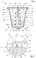
Figure 1 is a schematic cross section of a capsule according to the invention in a first operating step; -
Figure 2 is a top plan view of the capsule inFigure 1 , with a partially removed cover element to better highlight an underlying supporting element; -
Figure 3 and 4 are cross sections of the capsule inFigure 1 in subsequent operating dispensing steps; -
Figure 5 illustrates an enlarged detail ofFigure 3 showing, in particular, a base wall and an end of a nozzle of the capsule; -
Figure 6 is an enlarged cross section of the capsule infigure 1 in an operating step; -
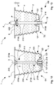
Figure 7 is an enlarged partial section of a version of the capsule of the invention; -
Figure 8 and 9 are enlarged and partial sections of respective further versions of the capsule of the invention; -
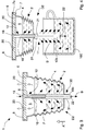
Figure 10 is a schematic cross section of another version of the capsule of the invention in a first operating step; -
Figure 11 is a schematic cross section of the capsule inFigure 10 in a second operating step; -
Figure 12 is a schematic cross section of another further version of the capsule of the invention in a first operating step; -
Figure 13 illustrates an enlarged detail ofFigure 12 showing, in particular, a base wall and an end of a nozzle of the capsule; -
Figure 14 is an enlarged partial section of the capsule inFigure 12 in a second operating step; -
Figure 15 is a partial section of another version of the capsule of the invention inFigure 10 ; -
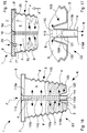
Figure 16 is a schematic cross section of a further version of the capsule of the invention in a first operating step; -
Figure 17 is an enlarged partial section of the capsule inFigure 16 in a second operating step; -
Figure 18 is a schematic cross section of another version of the capsule of the invention in a first operating step; -
Figure 19 is a schematic cross section of the capsule inFigure 18 in a second operating step. -
Figure 20 is a schematic exploded cross section of another version of the capsule of the invention; -
Figure 20a is an enlarged plan view of a filtering element comprised in the capsule inFigure 20 ; -
Figure 21 is a schematic cross section of the capsule inFigure 20 in a first operating step; -
Figure 22 is a cross section of the capsule inFigure 20 in a second operating dispensing step. - With reference to
figures 1 to 6 , acapsule 1 for beverages according to the invention is illustrated, that is usable in a dispensing machine to produce a foodstuff final product, for example a beverage such as coffee, barley, herbal tea, tea, chocolate, etc, by injecting a pressurised fluid into the capsule. The initial product is percolatable or soluble or infusion or freeze-dried or dehydrated or concentrated foodstuff product. - The
capsule 1 comprises anexternal casing 2 or container that is substantially glass or cup-shaped that is provided with abase wall 3 and with aside wall 4 that define acavity 5 that is open and suitable for containing the initial product P from which to obtain the final product B. - The
casing 2 is compressible and/or crushable and/or deformable, is made by forming a sheet of thermoformable material, in particular a multilayered plastic material that is impermeable to liquids and gases and is suitable for contact with foodstuffs. - In order to enable the
casing 2 to be compressed and crushed along a direction A that is substantially parallel to a longitudinal axis X of thecapsule 1 and is substantially orthogonal to thebase wall 3, theside wall 4 is deformable and/or compressible along preset compliance lines, for example having a helical shape or is concertina or bellows-shaped, as in the illustrated embodiment. - Further, the
side wall 4 diverges from thebase wall 3 up to a peripheral flange-shapededge 7, for example with an almost frustoconical shape. - The
capsule 1 further comprises a supportingelement 6 fixed to theedge 7 of thecasing 2 and facing thecavity 5 and to which anozzle 10 is fixed that is arranged for delivering a fluid F into thecavity 5, in particular a hot pressurised liquid, for example water or milk, that is able to interact with the initial product P to make the final product B, in a first operating step D1 preparing the latter. - The
edge 7 has anannular seat 7a that receives a peripheral edge of the supportingelement 6 that can be fixed there by welding or gluing. - The
nozzle 10 of elongated rectilinear shape is provided with a plurality ofopenings cavity 5 in the first operating step D1. Thenozzle 10 is engaged in anoutflow portion 30 of thebase wall 3 and arranged for exiting from saidcavity 5 through theoutflow portion 30 when thecasing 2 is compressed and crushed, in a second operating step D2. In particular, thenozzle 10 is configured and shaped in such a manner as to pierce theaforesaid outflow portion 30 and exit from thecavity 5. - The
nozzle 10 comprises a stiff, for example cylindrical, tubular element having arespective side wall 10a provided with a plurality ofopenings 21 and a sharpenedend 10b that is able to pierce theoutflow portion 30. - In an initial configuration K of the
capsule 1, in which thecasing 2 is not compressed or crushed, thenozzle 10 is arranged completely inside thecavity 5 and parallel to the longitudinal axis X of thecapsule 1, for example substantially coaxial with the latter, with theend 10b inserted into theoutflow portion 30. - The
nozzle 10 comprises afirst portion 11 arranged for abutting on, and sliding in a sealed manner inside theoutflow portion 30, such that the final product B exits from thecavity 5 only through thenozzle 10 when thecasing 2 is compressed and/or crushed. For this purpose, theoutflow portion 30 comprises anannular wall 31 arranged for abutting in a sealed manner on arespective side wall 10a of thenozzle 10. The cross sections of thenozzle 10, at thefirst portion 11, and at theannular wall 31 have a complementary shape. In order to ensure the seal, thenozzle 10 is inserted into and slides with interference inside theannular wall 31. - In the illustrated embodiment, the
annular wall 31 projects externally in relation to thecavity 5. Alternatively, theannular wall 31 and theentire outflow portion 30 can extend inside thecavity 5. - The
outflow portion 30 further comprises abottom wall 32 connected to theannular wall 31, in such a manner as to form aspace 35 that is suitable for partially housing theend 10b of thenozzle 10. Thebottom wall 32 is easily breakable by theend 10b of thenozzle 10 when thecasing 2 is compressed and crushed. For this purpose, thebottom wall 32 is made with a reduced wall thickness. - Alternatively, the
bottom wall 32 can comprise a pre-cutting line or a weakening portion that facilitates perforating by thenozzle 10. - The
end 10b of thenozzle 10 is provided with at least onefurther opening 22 arranged for dispensing the fluid F inside thecavity 5 during the first operating step D1 when thecasing 2 is in the initial configuration K, i.e. is not compressed or crushed, or for dispensing the fluid F and/or the final product B directly into aconsumption container 100 when saidcasing 2 is compressed and crushed, in the subsequent second operating step D2, as explained better below in the description. - The
openings 21 are distributed along theside wall 10a of thenozzle 10 in such a manner that in the first operating step D1, when thecasing 2 is in the initial configuration K, they dispense the fluid F into thecavity 5; in the subsequent second operating step D2, as explained further on in the description, when thecasing 2 is compressed and crushed and thenozzle 10 progressively exits from thecavity 5, theopenings 21 situated inside the latter receive and/or suck the final product B and/or a mixture of said initial product P and said fluid F, whilst theopenings 21 situated outside thecavity 5 dispense the final product B and/or the fluid F into theconsumption container 100. - The
openings 21 are spaced angularly apart from one another and linearly along theside wall 10a of thenozzle 10 and are tilted towards thebase wall 3, for example by an angle of 45° with respect to the longitudinal axis X. In this manner theopenings 21 dispense a plurality of fluid jets F towards thebase wall 3 or the final product B inside theconsumption container 100, when theaforesaid openings 21 are situated respectively inside or outside thecavity 5. - The
nozzle 10 further comprises asecond portion 12 adjacent to thefirst portion 11 and spaced away from thebase wall 3, in particular interposed between thefirst portion 11 and the supportingelement 6, saidsecond portion 12 being provided with a cross section that is less than that of thefirst portion 11 and anyway such as to enable the final product B to exit from saidcavity 5 through a passage defined by saidoutflow portion 30 and saidsecond portion 12, when thecasing 2 is compressed and crushed so as to bring saidsecond portion 12 to theaforesaid outflow portion 30. In this manner the beverage B contained in thecapsule 1 can substantially exit through gravity. - In the embodiment illustrated in
figures 1 to 6 , thesecond portion 12 has a substantially circular cross section, like that of thefirst portion 11, but with a smaller diameter in such a manner as not to abut on theannular wall 31. As illustrated infigure 6 , theside wall 10a of thenozzle 10 at thesecond portion 12 and theannular wall 31 of theoutflow portion 30 define, or form, the passage through which the final product B can exit. - The shape of the cross section of the
second portion 12 can also be oval or polygonal, such as to make with theannular wall 31 of theoutflow portion 30 an outlet passage for the final product B. - A
cover element 8 is fixed to thefirst edge 7 and/or to anexternal face 6a of the supportingelement 6 to close thecapsule 1 hermetically. Thecover element 8, which typically comprises a film of aluminium or plastics, is perforable by injecting means of a dispensing machine that is suitable for receiving thecapsule 1 of the invention. - The supporting
element 6 comprises a body having a substantially flat shape, for example a disc, and which is provided with one ormore openings 18, for example two, for introducing the product P into thecavity 5 of thecapsule 1, during a filling step of the latter. - The supporting
element 6 includes aninternal face 6b that is opposite theexternal face 6a and to which thenozzle 10 is fixed. Theexternal face 6a is provided with asupply hole 19 that is in a flowing connection with aninternal conduit 10c of saidnozzle 10 and can be engaged by injecting means of a dispensing machine that is suitable for dispensing said fluid F. - The supporting
element 6 further comprises at least onevent hole 20 to enable the air or inert gas contained in thecapsule 1 to exit when the fluid F is introduced into thecavity 5. Also thevent hole 20 can be engaged by the injecting means of the dispensing machine. The supportingelement 6 and thenozzle 10 can be made of a single body, for example by a process of injection moulding of plastics. - It should be noted that owing to the supporting
element 6 provided withsupply hole 19 and venthole 20 the injecting means of the dispensing machine does not come into contact with the initial product P and/or with the mixture/final product B during the preparation step and subsequently during the dispensing step. In other words, a supply circuit of the machine that comprises the injecting means is not dirtied or polluted with the initial and/or final product, this ensuring the hygiene of the dispensing process and the quality of the final products at each dispensing, preserving the organoleptic properties thereof. - The operation or use of the
capsule 1 of the invention in a dispensing machine provides in the first operating step D1 the delivering inside thecavity 5 of the fluid F through theopenings 21 of thenozzle 10. Thenozzle 10 is for example supplied by injecting means of the dispensing machine that is able to perforate thecover element 8 and engage thesupply hole 19. - In this step the inert air and/or gas in the
cavity 5 can exit through thevent hole 20, which is also opened by the injecting means of the dispensing machine. - The fluid F introduced by a plurality of jets through the
openings 21 can interact with the initial product P to form the final product B, typically a beverage, slowly. In this step, thecasing 2 of thecapsule 1 is in the initial configuration K, i.e. it is not compressed or crushed and theend 10b of the nozzle is engaged, inserted in a sealed manner in theoutflow portion 30, which is whole. - Once the final product B has been obtained, after a preset time and/or a preset quantity of delivered fluid F, in the second operating step D2 the
cavity 5 is isolated by closing thevent hole 20 and thecasing 2 is progressively compressed and crushed along the direction A so as to enable thenozzle 10 to pierce theoutflow portion 30 and in particular thebottom wall 32 and exit from thecavity 5. - As the
first portion 11 of thenozzle 10 abuts on and slides in a sealed manner inside theannular wall 31 of theoutflow portion 30, the final product B can exit from thecavity 5 initially only through thefurther opening 22 and subsequently, when the nozzle extends progressively to the outside of thecapsule 1 through theopenings 21 that become external to thecavity 5. - As the
cavity 5 is closed (thevent hole 20 is closed), by crushing and compressing thecasing 2 the final product B contained therein is forced to exit by the pressure through theopenings 21 located inside thecavity 5. - By continuing the compressing and crushing of the
casing 2, thesecond portion 12 of thenozzle 10 is inserted into theoutflow portion 32 thus opening a passage for the complete exit of the final product B from the capsule 1 (Figure 6 ). - If the volume of the
cavity 5 corresponds to the final volume to be dispensed into the consumption container, during the second operating step D2 thenozzle 10 is not supplied by the injecting means of the dispensing machine with further fluid F. - If, on the other hand, the volume of the
capsule 1 is less than that of the final volume to be dispensed into the consumption container, during the second operating step D2 thenozzle 10 is supplied by the injecting means with further fluid F. The latter is dispensed directly into theconsumption container 100 to dilute final product B to the desired concentration. - It is as well to observe that with initial percolation or infusion products (such as, for example, tea, or herbal teas or infusions) the
nozzle 10 acts substantially as a filter as theopenings 21 in the second operating dispensing step D2, as disclosed above, retain and lock inside thecavity 5 non soluble particles and bodies (for example tea leaves or coffee grounds) of the initial product P, whereas they enable the final product B thereby obtained to exit. - The
nozzle 10 further enables initial products that are hardly or slowly soluble and/or containing thickening agents and/or stabilisers or freeze-dried or dehydrated products to be solubilised and dissolved completely without the manual intervention of a user so as to obtain dense or viscous final products (for example chocolate) that are perfectly dissolved and devoid of clots and lumps. During the dispensing step (second operating step D2), when thecasing 2 is compressed and crushed, the mixture of initial product P and of fluid F is in fact forced to traverse theopenings 21 of thenozzle 10, and in this manner it is mixed, solubilised and dissolved. - The dimensions, shape, tilt, number and arrangement of the
openings 21 on thenozzle 10 can be suitably selected according to the type and composition of the initial product P. Thecapsule 1 of the invention also has the advantage of dispensing the final product B directly into a consumption container 100 (cup, glass, etc.) without the need to be perforated below. By compressing and crushing thecapsule 1, i.e. thecasing 2, thenozzle 10 opens theoutflow portion 30 of thebase wall 3 and enables the final product B to exit in a controlled manner through thefurther opening 22 and, subsequently, through theopenings 21, directly into the consumption container. - The
capsule 1 of the invention can thus be used on a dispensing machine devoid of a dispensing circuit as this capsule does not require extracting means suitable for piercing the bottom thereof to enable the beverage to exit or conduit means for conveying the beverage to the consumption container (for example a mug, a cup, a glass, etc.). - The absence of the dispensing circuit makes the dispensing machine simpler and cheaper and further ensures the hygiene of the dispensing process and the maintenance of the quality of the dispensed beverages as contamination between subsequently dispensed beverages is impossible.
- A further advantage of the
capsule 1 is that it does not require a special sealed package as thewall 3 and theoutflow portion 30 hermetically isolate thecavity 5 from the external environment so as to preserve the initial product P. - The
figure 7 illustrates one version of thecapsule 1 of the invention that differs from the previously disclosed embodiment, through the fact of comprising anoutflow portion 40 provided with anoutlet hole 42, hermetically closed by aclosing element 43 that is fixed externally to theperipheral wall 41 of theaforesaid outflow portion 40 and forms with said peripheral wall thespace 45 that is suitable for partially housing theend 10b of thenozzle 10. The closingelement 43 is, for example a film of plastics or aluminium that is perforable or at least partially detachable from theend 10a when thecasing 2 is compressed and crushed. - With reference to
figure 8 , another version of thecapsule 1 of the invention is provided that differs from the previously disclosed embodiment through the fact of comprising adifferent nozzle 50. The latter comprises afirst portion 51 devoid of an opening on the side wall and asecond portion 52 with a variable section that is on the other hand provided with a plurality ofopenings 55. In particular, thesecond portion 52 comprises a first part, adjacent to thefirst portion 51, with a reduced section to enable the final product B to exit through the outflow portion 30 (when the casing is substantially completely compressed and crushed) and a second part, adjacent to the supportingelement 6, the second part having a divergent section and being provided withopenings 55. The end of thenozzle 50 has one or more further openings. - In the first operating step D1 the initial product P on the bottom of the capsule is sprinkled from above by the fluid F delivered through the
openings 55. - In the second operating step D2, the compressing and crushing of the
casing 2 push the final product B to enter through theopenings 55 in thenozzle 50 to exit from the end in theconsumption container 100. -
Figure 9 illustrates a further version of thecapsule 1 of the invention that is distinguished from the embodiment inFigure 1 by thenozzle 60 that comprises asecond portion 62, comprised between thefirst portion 61 provided withopenings 65 and the supportingelement 6, provided with a plurality ofgrooves 63, for example longitudinal, that form with theannular wall 31 of theoutflow portion 30 the outlet passage for the final product B. - With reference to
figures 10 and 11 , another further version of thecapsule 1 of the invention is provided that is distinguished from the previously disclosed embodiments by thedifferent nozzle 70. The latter comprises afirst portion 71 that extends from theend 70b to the supportingelement 6, i.e. it is devoid of a second portion with a reduced section. Thefirst portion 11 is provided along its entire length of a plurality ofopenings 75 made on theside wall 70a that are angularly and linearly spaced apart from one another. - In the first operating step D1 the initial product P located in the
cavity 5 is sprinkled by the fluid F delivered through theopenings 75. After an infusion step, in the second operating step D2, thecasing 2 is partially compressed and crushed in such a manner that thenozzle 70 can open theoutflow portion 30. Thevent hole 20 is maintained open to enable the air to exit from thecavity 5. In this manner the final product B can exit by gravity through theopenings 75 and thefurther opening 76 provided on theend 70b of the nozzle. Dispensing does not in this case require the casing to be completely crushed. This capsule version is particularly suitable for producing beverages from initial infusion products. -
Figures 12 to 15 illustrate still another version of thecapsule 1 of the invention that is distinguished from the previously disclosed embodiments by the different conformation of thenozzle 80 and of theoutflow portion 90 of thebase wall 3. - The
nozzle 80 is substantially similar to the nozzle of thecapsule 1 illustrated infigures 1 to 4 , differing by thedifferent end 80b having a substantially flared shape. More precisely, theend 80b has afurther opening 82 for dispensing the fluid F having a section that is equal to the internal cross section of the nozzle and an edge orexternal flange 80d that peripherally surrounds thefurther opening 82. - The
outflow portion 90 is open, i.e. it has anoutlet hole 94 that is nevertheless closed in a sealed manner by thenozzle 80. Theoutflow portion 90 in fact comprises anannular wall 91 that extends, for example, inside thecavity 5 and forms theoutlet hole 94. Theannular wall 91 is intended to engage in a sealed manner therespective side wall 80a of thenozzle 80, at thefirst portion 83 of the latter. The cross sections of thenozzle 80, at thefirst portion 83, and of theannular wall 91, have complementary shapes. In order to ensure the seal, thenozzle 80 is inserted into and slides with interference inside theannular wall 91. In an initial configuration K of thecapsule 1 and during the first operating step D1, when thecasing 2 is in the original shape i.e. is not compressed or crushed, theend 80b of thenozzle 80 is inserted (through the outlet hole 94) and engages in a sealed manner theoutflow portion 90. In particular, theside wall 80a abuts in a sealed manner on theannular wall 91, whereas theflange 80d abuts on an external surface of thebase wall 3. Afurther closing element 93 is provided to close hermetically thefurther opening 82 of thenozzle 80 and preserve and insulate from the external environment the product P contained in the capsule. Thefurther closing element 93 further prevents the fluid F and/or the beverage B from exiting from thecapsule 1 during the first operating step D1 when the fluid F is delivered into thecavity 5 through theopenings 81 of the nozzle 80 (Figure 13 ). - The
further closing element 93 is fixed removably to an external surface of thebase wall 3 and can be easily detached by a user before introducing thecapsule 1 into the dispensing machine or from thenozzle 80 in the second operating step D2. In this operating step, similarly to what occurs for the previously disclosed capsules, thecavity 5 is insulated by closing thevent hole 20 and thecasing 2 is progressively compressed and crushed along the direction A so as to enable thenozzle 80 to detach thefurther closing element 93 and exit from thecavity 5 to dispense through thefurther opening 82 the beverage B into the consumption container. In the second operating step D2, theopenings 81 situated inside thecavity 5 receive the final product B and/or a mixture of said initial product P and said fluid F, whereas theopenings 81 that are outside thecavity 5 dispense the final product B and/or the fluid F in the consumption container. - Alternatively, the
further closing element 93 can be removably fixed to theexternal flange 80d in such a manner as to close hermetically thefurther opening 82. In this case, thefurther closing element 93 has to be detached by the user before introducing thecapsule 1 into the dispensing machine. - The
figure 15 illustrates one embodiment of the capsule inFigure 10 comprising afurther nozzle 77 fixed to the supporting element 6'. The latter includes on theexternal face 6a' afurther supply hole 23 that is flowingly connected to an internal conduit of saidfurther nozzle 77 and can be engaged by the injecting means of the dispensing machine. - The
further nozzle 77 can be used in the second operating step D2 to inject the fluid F inside thecavity 5, whilst thenozzle 70 dispense the beverage B into the consumption container. - A further nozzle can also be provided for the capsules of the invention illustrated in
figures 1 to 9 . - With reference to
figures 16 and 17 , another version of thecapsule 1 of the invention is illustrated that is distinguished from the previously disclosed embodiments by the fact that it is devoid of the supporting element of the nozzle fixed to anedge 7 of thecasing 2. In this case thenozzle 110 is engaged in a sealed manner and supported - substantially maintained in an erect position - by theoutflow portion 120 of thebase wall 3. Theoutflow portion 120 is open and has arespective outlet hole 124 that is nevertheless closed in a sealed manner by thenozzle 110. Theoutflow portion 120 comprises anannular wall 121 that forms theoutlet hole 124 and is intended to engage in a sealed manner and support arespective side wall 110a of thenozzle 110, at afirst portion 111 of the latter. The cross sections of thenozzle 110, at thefirst portion 111, and of theannular wall 121 have a complementary shape. In order to ensure the seal, thenozzle 110 is inserted into and slides with interference inside theannular wall 121. The length of the latter in the direction parallel to the longitudinal axis X is such as to support appropriately and maintain in a substantially erect position thenozzle 110, which does not therefore need to be fixed to a supporting element. - The
outflow portion 120 further comprises a connectingwall 122 that connects theannular wall 121 to thebase wall 3. - The
nozzle 110 comprises afirst portion 111 provided withopenings 113 spaced angularly apart from one another around and linearly along theside wall 110a in such a manner as to enable a plurality of fluid jets F to be dispensed inside thecavity 5. Thenozzle 110 comprises anend 110b having a substantially flared shape. More precisely, theend 110b has afurther opening 114 for dispensing the fluid F the section of which is equal to the internal cross section of the nozzle and a respective edge orexternal flange 110d that peripherally surrounds thefurther opening 114. - The
nozzle 110 comprises afurther end 110e opposite saidend 110b and provided with a further access opening 115 giving access to aninternal conduit 110c of thenozzle 110. Thefurther end 110e is arranged for engaging with injecting means of a dispensing machine that is suitable for dispensing said fluid F. - The
capsule 1 is provided with acover element 8 fixed to theedge 7 of thecasing 2 to close hermetically thecavity 5 and is perforable by injecting means of a dispensing machine. Thecover element 8 can be further fixed to thefurther end 110e in such a manner as contributing to supporting thenozzle 110. - In an initial configuration K of the
capsule 1 and during the first operating step D1, when thecasing 2 is in the original shape i.e. is not compressed or crushed, theend 110b of thenozzle 110 is inserted into theoutlet hole 124 and engages theoutflow portion 120 in a sealed manner. In particular, theside wall 110a abuts in a sealed manner on theannular wall 121, whereas theexternal flange 110d abuts on an external surface of thebase wall 3. Afurther closing element 123 is provided to close hermetically thefurther opening 114 of thenozzle 110 and preserve and insulate from the external environment the product P contained in the capsule. Thefurther closing element 123 further prevents the fluid F and/or the beverage B of thecapsule 1 from exiting during the first operating step D1 when the fluid F is delivered into thecavity 5 through theopenings 113 of the nozzle 110 (Figure 16 ). - The
further closing element 123 is removably fixed to theexternal flange 110d of the nozzle and/or to an external surface of thebase wall 3 and can be easily detached by a user before thecapsule 1 is introduced into the dispensing machine or by thenozzle 110 in the second operating step D2. - In the second operating step D2, similarly to what occurs for the capsules disclosed previously, at the end of dispensing of the fluid F into the cavity 5 (and of a possible period of infusion of the product P), the
casing 2 is compressed and crushed along the direction A so as to enable thenozzle 110 to exit from the cavity 5 (possibly detaching the further closing element 123) to dispense through thefurther opening 114 the beverage B into the consumption container. - In the second operating step D2, the
openings 113 situated inside thecavity 5 receive the final product B, whereas theopenings 113 located outside thecavity 5 dispense the final product B and/or the fluid F into the consumption container. - If the
casing 2 is partially compressed and crushed in such a manner as to enable thenozzle 110 to exit from theoutflow portion 120, one vent hole can be made on thecover element 8 to enable the air to exit from thecavity 5. In this manner, the final product B can exit by gravity through thefurther opening 114. In this case, dispensing does not require the casing to be crushed completely. - With reference to
figures 18 and 19 , there is illustrated another version of thecapsule 1 of the invention that is distinguished from the embodiment disclosed above and illustrated infigures 16 and 17 by thenozzle 210 that comprises afirst portion 211 devoid of openings and asecond portion 212 provided with a plurality offurther openings 222. Thesecond portion 212, adjacent to thefirst portion 211 has a shape that substantially diverges from thefirst portion 211, in such a manner as to be locked in theoutflow portion 120 without exiting from thecavity 5 when thecasing 2 is compressed and crushed. - The
nozzle 210 is engaged in a sealed manner and supported in an erect position by theoutflow portion 120 of thebase wall 3. Theoutflow portion 120 is open and has arespective outlet hole 124 that is closed in a sealed manner by thenozzle 210. Theoutflow portion 120 comprises anannular wall 121 that forms theoutlet hole 124 and is intended to engage in a sealed manner and support arespective side wall 210a of thenozzle 210, at thefirst portion 211 of the latter. The length of theannular wall 121 in the direction parallel to the longitudinal axis X is such as to support appropriately and maintain in a substantially erect position thenozzle 210, which does not therefore need to be fixed to a supporting element. - The
outflow portion 120 further comprises a connectingwall 122 that connects theannular wall 121 to thebase wall 3. - The
nozzle 210 also in this embodiment comprises anend 210b that has a substantially flared shape and is provided with afurther opening 214 for dispensing the fluid F having a section that is equal to the internal cross section of the nozzle and a respective edge orexternal flange 210d that surrounds thefurther opening 214. - The
nozzle 110 comprises afurther end 210e opposite theend 110b, i.e. at thesecond portion 212 and provided with a further access opening 215 giving access to aninternal conduit 210c of thenozzle 210. Thefurther end 210e is arranged for engaging with injecting means of a dispensing machine that is suitable for dispensing said fluid F. - A
cover element 8 is fixed to theedge 7 of thecasing 2 to close hermetically thecavity 5 and is perforable by injecting means of a dispensing machine. Thecover element 8 can be further fixed to thefurther end 210e in such a manner as to contribute to supporting thenozzle 210. - In an initial configuration K of the
capsule 1 thecasing 2 is in the original shape, i.e. is not compressed or crushed, and theend 210b of thenozzle 210 is inserted into theoutlet hole 124 and engages in a sealed manner theoutflow portion 120. In particular, theside wall 210a abuts in a sealed manner on theannular wall 121, whereas theexternal flange 210d abuts on an external surface of thebase wall 3. - A
further closing element 123 is provided to close hermetically thefurther opening 214 of thenozzle 210 so as to preserve and insulate from the external environment the product P contained in the capsule and prevent the initial product P from exiting. - The
further closing element 123 is removably fixed to anexternal flange 210d of the nozzle and/or to an external surface of thebase wall 3 and can be easily detached by a user before thecapsule 1 is introduced into the dispensing machine or by thenozzle 210. - This capsule is suitable for liquid initial products, for example concentrated solutions to be diluted during dispensing.
- Using this version of the
capsule 1 provides in the first operating step D1 that the injecting means of the dispensing machine pierce thecover element 8 to engage in a sealed manner thefurther end 210e of thenozzle 210 without, however, delivering the fluid. - The second operating step D2 is divided into two successive substeps. In a first stage (opening substep) the
casing 2 is compressed and crushed along the direction A, so as to enable the bottom of thecapsule 1 to open through detachment of thefurther closing element 123, a detachment that can occur both owing the increase of pressure inside the capsule and the action of thenozzle 210 that progressively exits from thecavity 5. The air contained inside thecavity 5 can exit by passing from thefurther openings 222 through theinternal conduit 210c of thenozzle 210. - Subsequently (dispensing and dilution substep), the
casing 2 is further compressed and crushed along the direction A and the fluid F is delivered by the injecting means in thenozzle 210 in such a manner that the initial product P exits from thecapsule 1 through thefurther openings 222 of thenozzle 210 and in theinternal conduit 210c it joins and mixes with the fluid F. Into the consumption container a final product B is then dispensed that is suitably diluted from a concentrated initial product P (Figure 19 ). - The quantity of initial product P inside the cavity 5 (level) is such as to enable the initial product P to exit from the
further openings 222 only when theend 210b of thenozzle 210 is no longer covered by thefurther cover element 123. - Dispensing of the fluid F can last as long as crushing of the
casing 2, or last longer. In this latter case, the final product B will be further diluted inside the consumption container. - At the end of crushing of the
casing 2 thesecond portion 212 and thefurther openings 222 remain inside thecapsule 1. - Owing to the capsule of the invention it is thus possible to dilute, or mix or blend in an optimum manner the initial product P, typically a concentrated liquid solution, with the dilution fluid. This dilution/mixing, which occurs directly inside of the
nozzle 210, enables a final product that is already ready to be dispensed into the consumption container. - With reference to
figures 20, 21 and 22 , there is illustrated another version of thecapsule 1 of the invention that is distinguished from the previously disclosed embodiments by the fact that it comprises afiltering element 300 fixed to thenozzle 310. The latter, also in this embodiment comprises afirst portion 311 that ends with anend 310b provided with afurther opening 314 for dispensing the fluid F or the final product B that has a section that is equal to the internal cross section of the nozzle and a respective edge orexternal flange 310d that surrounds thefurther opening 314. As in the embodiments of the capsule disclosed previously, also in this version thenozzle 310 comprises openings (not shown) through which the fluid F is introduced inside thecavity 5 of thecapsule 1 to interact with the initial product P in such a manner as gradually to form the final product B. These openings substantially act as filters, because they retain and lock inside thecavity 5 non soluble particles and bodies (for example tea leaves or coffee grounds) of the initial product P, whereas they enable the thus obtained final product B to exit freely. - As more clearly visible in the view in
Figure 20a , thefiltering element 300 comprises anexternal edge 300a thermowelded to theexternal flange 310d and afiltering zone 300b facing thefurther opening 314 and arranged for being traversed by the fluid F or by the final product B. - Alternatively, the
external edge 300a can be glued to theexternal flange 310d by a suitable adhesive of known type. - The fluid F or the product B exiting from the
opening 314 traverse thefiltering zone 300b before reaching the consumption container. Thefiltering zone 300b thus enables possible micro-powders and micro-residues of the initial product P to be retained inside thecavity 5 in such a manner as to prevent the drop thereof inside the consumption container. - Also in this embodiment the
capsule 1 comprises afurther closing element 323 to close hermetically thefurther opening 314 of thenozzle 110 and preserve and insulate from the external environment the product P contained in the capsule. Thefurther closing element 323 further prevents the fluid F and/or of the beverage B from exiting from thecapsule 1 during the first operating step D1 (Figure 21 ). Thefurther closing element 323 is arranged in such a manner as to cover, and protect, thefiltering element 300, as seen better from the exploded view inFigure 20 . - The
further closing element 323 is removably fixed to an external surface of thebase wall 3 and can be easily detached from thenozzle 310 in the second operating step D2 (Figure 22 ).
Claims (15)
- Capsule comprising a deformable and/or compressible casing (2) that is provided with a base wall (3) and with a side wall (4) that define a cavity (5) containing an initial product (P) to be joined to a fluid (F) to obtain a final product (B), characterised in that- said side wall (4) is deformable and/or compressible along preset compliance lines to enable said casing (2) to be compressed and crushed along a direction (A) that is transverse, in particular orthogonal, to said base wall (3); and in that- the capsule comprises a nozzle (10; 50; 60; 70; 80; 110; 210; 310) provided with a plurality of openings (21, 22; 55; 65; 75, 76; 81, 82; 113, 114; 214, 222; 314) for the passage of said fluid (F), said nozzle (10; 50; 60; 70; 80; 110; 210; 310) being engaged with an outflow portion (30; 40; 90; 120) of said base wall (3) and arranged for exiting from said cavity (5) through said outflow portion (30; 40; 90; 120) when said casing (2) is compressed and/or crushed,- wherein said nozzle (10; 50; 60; 70; 90; 110; 210; 310) comprises a first portion (11; 51; 61; 71; 83; 111; 211; 311) arranged for abutting on, and sliding with interference inside said outflow portion (30; 40; 90; 120) in a sealed manner such that said final product (B) exits at least initially from said cavity (5) only through at least one further opening (22; 76; 82; 114; 214; 314) of said nozzle (10; 50; 60; 70; 80; 110; 210; 310).
- Capsule according to claim 1, wherein said nozzle (10; 50; 60; 70; 80; 110) comprises a stiff tubular element having a respective side wall (10a; 80a; 110a; 210a) provided with said plurality of openings (21; 81; 113; 222) and an end (10b; 80b; 110b; 210b) engaged in said outflow portion (30; 40; 90; 120) in an initial configuration (K) in which said casing (2) is not compressed or crushed.
- Capsule according to claim 2, wherein said end (10b; 80b; 110b; 210b) is provided with at least said further opening (22; 82; 114; 214) arranged for dispensing said fluid (F) and/or said final product (B) directly into a consumption container (100) when said casing (2) is compressed and/or crushed.
- Capsule according to claim 2 or 3, wherein said nozzle (110; 210) comprises a further end (110e; 210e) opposite said end (110b; 210b), provided with a respective further opening (115; 215) and arranged for engaging injecting means of a dispensing machine that is suitable for dispensing said fluid (F).
- Capsule according to any preceding claim, wherein said openings (21; 61; 71; 81; 113) are distributed along said nozzle (10; 60; 70; 80; 110) in such a manner that in a first operating step (D1), wherein said casing (2) is not crushed or compressed, said openings (21; 61; 71; 81; 113) dispense said fluid (F) into said cavity (5) and in a second operating step (D2) when said casing (2) is compressed and/or crushed and said nozzle (10; 60; 70; 80; 110) exits partially from the cavity (5), the openings (21; 61; 71; 81; 113) situated inside the cavity (5) receive the final product (B) and/or a mixture of said initial product (P) and said fluid (F), whereas the openings (21; 61; 71; 81; 113) situated outside the cavity (5) dispense said final product (B) and/or said fluid (F) in a consumption container (100).
- Capsule according to any preceding claim, wherein said outflow portion (30; 40; 90; 120) comprises an annular wall (31; 41; 91; 121) arranged for abutting in a sealed manner on a respective side wall (10a; 80a; 110a; 210a) of said nozzle (10; 80; 110; 210) at said first portion (11; 51; 61; 71; 83; 111; 211), and optionally wherein said annular wall (121) is arranged for supporting and maintaining substantially erect said nozzle (110; 210).
- Capsule according to claim 6, wherein said outflow portion (30) comprises a bottom wall (32) connected to said annular wall (31) in such a manner as to form a space (35) that is suitable for housing an end (10b) of said nozzle (10), said bottom wall (32) being breakable by an end (10b) of said nozzle (10) when said casing (2) is compressed and/or crushed or wherein said outflow portion (40) comprises an outlet hole (42) hermetically closed by a closing element (43) that is fixed externally to said peripheral wall (41) and forms with the latter a space (45) that is suitable for housing an end (10b) of said nozzle (10), said closing element (43) being perforable or detachable from said end (10b) of said nozzle (10) when said casing (2) is compressed and crushed.
- Capsule according to claim 6, wherein said outflow portion (90; 120) comprises an outlet hole (94; 124), hermetically closed by said nozzle (80; 110; 210).
- Capsule according to claim 8, comprising a further closing element (93; 123) fixed removably to a peripheral edge (80d; 110d; 210d) of an end (80b; 110b; 210b) of said nozzle (80; 110; 210) and/or to an external surface of said base wall (3) such as to close hermetically at least said further opening (82; 114; 214).
- Capsule according to any preceding claim, wherein said nozzle (10; 50; 60) comprises a second portion (12; 52; 62) adjacent to said first portion (11; 51; 61) and spaced away from said base wall (3), said second portion (12; 52; 62) being provided with a cross section that is such as to enable said final product (B) to exit from said cavity (5) through a passage defined by said outflow portion (30) and said second portion (12; 52; 62) when said casing (2) is compressed and/or crushed so as to bring said second portion (12; 52; 62) at said outflow portion (30).
- Capsule according to any preceding claim, comprising a cover element (8) fixed to an edge (7) of said casing (2) to close hermetically said capsule (1), said cover element (8) being in particular perforable by injecting means of a dispensing machine that is suitable for receiving said capsule (1).
- Capsule according to claim 11, as appended to claim 4, wherein said cover element (8) is further fixed to said further end (110e; 210e).
- Capsule according to any preceding claim, comprising a supporting element (6; 6') fixed to a first edge (7) of said casing (2) and facing said cavity (5), said nozzle (10; 50; 60; 70; 90) being fixed to said supporting element (6; 6').
- Capsule according to any preceding claim, comprising a filtering element (300) fixed to said nozzle (310), optionally wherein said filtering element (300) comprises an external edge (300a), welded to an external flange (310d) of an end (310b) of said nozzle (310), and a filtering zone (300b) facing said further opening (314) and arranged for being traversed by said fluid (F) and/or by said final product (B).
- Method for obtaining a final product (B) by delivering a fluid (F) inside a capsule (1) according to any preceding claim containing an initial product (P), comprising:- providing openings (21, 22; 55; 65; 75; 81, 82; 113, 114) in a nozzle (10; 50; 60; 70; 80; 110) of said capsule (1) and dispensing a defined quantity of said fluid (F) into a cavity (5) of said capsule (1) through said openings (21, 22; 55; 65; 75; 81, 82; 113, 114) in a first operating step (D1), wherein said capsule (1) is in an initial configuration (K) in which a casing (2) of said capsule (1) is not compressed or crushed;- providing a side wall (4) of said casing (2) with preset compliance lines to enable said casing (2) to be compressed and crushed along a direction (A) that is transverse, in particular orthogonal, to said base wall (3) in a second operating step (D2) such that said nozzle (10; 50; 60; 70; 80; 110) exits from an outflow portion (30; 40; 90; 120) of a base wall (3) of said capsule (1);- providing at least a first portion (11; 51; 61; 71; 81; 111) of said nozzle (10; 50; 60; 70; 80, 110) arranged for abutting on, and sliding with interference inside, said outflow portion (30; 40; 90; 120) in a sealed manner when said casing (2) is compressed and crushed, such that in said second operating step (D2) when said nozzle (10; 50; 60; 70; 80; 110) exits partially from said cavity (5), the openings (21; 65; 75; 81; 113) situated in said cavity (5) receive said final product (B) and/or a mixture of said initial product (P) and said fluid (F), whereas the openings (21; 65; 75; 81; 113) situated outside said cavity (5) dispense said final product (B) and/or said fluid (F) in a consumption container (100).
Applications Claiming Priority (2)
| Application Number | Priority Date | Filing Date | Title |
|---|---|---|---|
| IT000056A ITMO20120056A1 (en) | 2012-03-07 | 2012-03-07 | CAPPULE FOR BEVERAGES |
| PCT/IB2013/051789 WO2013132450A1 (en) | 2012-03-07 | 2013-03-06 | Capsule for beverage |
Publications (2)
| Publication Number | Publication Date |
|---|---|
| EP2822877A1 EP2822877A1 (en) | 2015-01-14 |
| EP2822877B1 true EP2822877B1 (en) | 2016-10-05 |
Family
ID=46000075
Family Applications (1)
| Application Number | Title | Priority Date | Filing Date |
|---|---|---|---|
| EP13720560.5A Active EP2822877B1 (en) | 2012-03-07 | 2013-03-06 | Capsule for beverage |
Country Status (6)
| Country | Link |
|---|---|
| US (1) | US9567155B2 (en) |
| EP (1) | EP2822877B1 (en) |
| CA (1) | CA2864845C (en) |
| ES (1) | ES2607443T3 (en) |
| IT (1) | ITMO20120056A1 (en) |
| WO (1) | WO2013132450A1 (en) |
Families Citing this family (35)
| Publication number | Priority date | Publication date | Assignee | Title |
|---|---|---|---|---|
| US10722066B2 (en) * | 2010-12-04 | 2020-07-28 | Adrian Rivera | Windowed single serving brewing material holder |
| US11832755B2 (en) * | 2007-07-13 | 2023-12-05 | Adrian Rivera | Brewing material container for a beverage brewer |
| WO2012010317A1 (en) * | 2010-07-22 | 2012-01-26 | Krüger Gmbh & Co. Kg | Portion capsule having an identifier |
| ITMO20120043A1 (en) * | 2012-02-22 | 2013-08-23 | Sarong Spa | CAPPULE FOR BEVERAGES |
| US8955696B2 (en) * | 2012-06-08 | 2015-02-17 | Tina Ting-Yuan Wang | Storage systems for milk bags |
| ITMO20130296A1 (en) * | 2013-10-17 | 2015-04-18 | Sarong Spa | CAPPULE FOR BEVERAGES |
| EP3336012A1 (en) | 2012-12-27 | 2018-06-20 | Sarong Societa' Per Azioni | Capsule for beverages |
| CN104955744B (en) | 2012-12-27 | 2017-04-12 | 萨龙股份公司 | Capsule for beverages |
| ITMO20130320A1 (en) * | 2013-11-20 | 2015-05-21 | Sarong Spa | CAPPULE FOR BEVERAGES |
| WO2015123612A1 (en) * | 2014-02-14 | 2015-08-20 | Remington Designs, Llc | Beverage brewer and related methods for brewing beverages |
| GB201402838D0 (en) * | 2014-02-18 | 2014-04-02 | The Technology Partnership Plc | Infusion cartridge and apparatus |
| US10442610B2 (en) * | 2014-03-11 | 2019-10-15 | Starbucks Corporation | Pod-based restrictors and methods |
| CH709598A2 (en) * | 2014-05-06 | 2015-11-13 | Delica Ag | Portionierbehälter for a capsule for drink preparation. |
| CN104071467A (en) * | 2014-06-26 | 2014-10-01 | 浙江爱仕达生活电器有限公司 | Beverage capsule of modified structure and use method thereof |
| KR102543218B1 (en) * | 2014-11-17 | 2023-06-14 | 아피크 홀딩스, 엘엘씨 | Disposable cartridge filled with a single serve portion of a liquid ingredient to be combined with a base liquid for the preparation of a liquid product |
| US10111554B2 (en) | 2015-03-20 | 2018-10-30 | Meltz, LLC | Systems for and methods of controlled liquid food or beverage product creation |
| US9487348B2 (en) | 2015-03-20 | 2016-11-08 | Meltz, LLC | Systems for and methods of providing support for displaceable frozen contents in beverage and food receptacles |
| US9346611B1 (en) | 2015-03-20 | 2016-05-24 | Meltz, LLC | Apparatus and processes for creating a consumable liquid food or beverage product from frozen contents |
| US10314320B2 (en) | 2015-03-20 | 2019-06-11 | Meltz, LLC | Systems for controlled liquid food or beverage product creation |
| JP2018513064A (en) * | 2015-03-23 | 2018-05-24 | アルトリア クライアント サービシーズ エルエルシー | Disposable package for beverage production equipment |
| ITUB20155198A1 (en) * | 2015-10-22 | 2017-04-22 | Sarong Spa | CAPPULE FOR BEVERAGES |
| CN111166174B (en) * | 2016-03-01 | 2022-12-16 | 贝塔什股份有限公司 | Beverage machine and capsule for use with a beverage machine |
| IT201600094474A1 (en) * | 2016-09-20 | 2018-03-20 | Pepeimpex Ltd | CAP FOR SOLUBLE MIXTURE |
| MX2019011066A (en) | 2017-03-17 | 2019-12-19 | Verbena 2017 B V | Capsule for preparing a beverage product. |
| IT201700043013A1 (en) | 2017-04-19 | 2018-10-19 | Bisio Progetti Spa | CAPS FOR THE PREPARATION OF INFUSION OR SOLUBLE BEVERAGES IN LOW PRESSURE EXTRACTION SYSTEMS |
| EP3614889A1 (en) | 2017-04-27 | 2020-03-04 | Meltz LLC | Method for centrifugal extraction and apparatus suitable for carrying out this method |
| IT201700047824A1 (en) * | 2017-05-03 | 2018-11-03 | Sarong Spa | Capsule for drinks |
| CO2017007101A1 (en) * | 2017-07-14 | 2019-03-08 | Camacho Juan Carlos Gonzalez | Beverage capsule |
| US11235920B2 (en) | 2018-06-08 | 2022-02-01 | Pepsico, Inc. | Beverage ingredient pod |
| IT201800007006A1 (en) * | 2018-07-06 | 2020-01-06 | Capsule for making a food product | |
| NL2022190B1 (en) | 2018-12-12 | 2020-07-03 | Douwe Egberts Bv | Air purge groove |
| US11724849B2 (en) | 2019-06-07 | 2023-08-15 | Cometeer, Inc. | Packaging and method for single serve beverage product |
| USD969547S1 (en) | 2020-04-16 | 2022-11-15 | Sarong Societa' Per Azioni | Coffee capsule |
| NL2025604B1 (en) * | 2020-05-18 | 2021-12-03 | Apiqe Holdings Llc | cartridge for providing a liquid product |
| US11805934B1 (en) * | 2020-10-21 | 2023-11-07 | Adrian Rivera | Brewing material lid and container for a beverage brewer |
Family Cites Families (9)
| Publication number | Priority date | Publication date | Assignee | Title |
|---|---|---|---|---|
| EP1586534A1 (en) * | 2004-02-18 | 2005-10-19 | MDS Global Holding Ltd. | Dispensing of a substance |
| GB0704095D0 (en) * | 2007-03-02 | 2007-04-11 | Mars Inc | Beverage preparation material |
| ITMO20070143A1 (en) | 2007-04-27 | 2008-10-28 | Massimiliano Pineschi | CAPSULE TO CONTAIN DOSAGES OF SOLUBLE BEVERAGES |
| AU2009242119A1 (en) * | 2008-04-30 | 2009-11-05 | Nestec S.A. | Sealed capsule for containing beverage ingredients and having an inlet-side membrane |
| JP4278706B1 (en) * | 2008-08-20 | 2009-06-17 | ユーシーシー上島珈琲株式会社 | Beverage extraction filter and method for producing the same |
| IT1395924B1 (en) * | 2009-09-25 | 2012-11-02 | Masciadri | CONTAINMENT CAPS OF A PRODUCT PARTICULARLY FOR THE PREPARATION OF A FOOD DRINK |
| NZ701718A (en) * | 2009-11-12 | 2016-09-30 | Formulanow Llc | Apparatus and method for preparing a liquid mixture |
| IT1399104B1 (en) * | 2010-03-26 | 2013-04-05 | Coffee Star S A | CAPSULE CONTAINING A DOSE OF A SUBSTANCE FOR THE PREPARATION OF A BEVERAGE, AND A METHOD FOR PREPARING A BEVERAGE USING THIS CAPSULE. |
| DE102010030988B4 (en) * | 2010-07-06 | 2012-04-05 | Brita Gmbh | container |
-
2012
- 2012-03-07 IT IT000056A patent/ITMO20120056A1/en unknown
-
2013
- 2013-03-06 WO PCT/IB2013/051789 patent/WO2013132450A1/en active Application Filing
- 2013-03-06 ES ES13720560.5T patent/ES2607443T3/en active Active
- 2013-03-06 US US14/382,663 patent/US9567155B2/en active Active
- 2013-03-06 EP EP13720560.5A patent/EP2822877B1/en active Active
- 2013-03-06 CA CA2864845A patent/CA2864845C/en active Active
Also Published As
| Publication number | Publication date |
|---|---|
| WO2013132450A1 (en) | 2013-09-12 |
| ITMO20120056A1 (en) | 2013-09-08 |
| EP2822877A1 (en) | 2015-01-14 |
| ES2607443T3 (en) | 2017-03-31 |
| CA2864845C (en) | 2021-01-26 |
| CA2864845A1 (en) | 2013-09-12 |
| US9567155B2 (en) | 2017-02-14 |
| US20150072052A1 (en) | 2015-03-12 |
| CN104302559A (en) | 2015-01-21 |
Similar Documents
| Publication | Publication Date | Title |
|---|---|---|
| EP2822877B1 (en) | Capsule for beverage | |
| EP3100963B1 (en) | Capsules and dispensing machine | |
| EP2817246B1 (en) | Capsule for beverage | |
| EP2941392B1 (en) | Capsule for beverages | |
| EP2802519B1 (en) | Capsule for beverage | |
| EP2330953B1 (en) | Method for preparing a food liquid contained in a capsule by centrifugation and system adapted for such method | |
| EP2404844B1 (en) | A capsule for preparation of a food product from a food preparation machine | |
| EP2343247B1 (en) | Capsule for containing doses of soluble drinks | |
| TWI683643B (en) | Pod for beverage machine | |
| AU2009289674B9 (en) | Method for preparing a food liquid contained in a capsule by centrifugation and system adapted for such method |
Legal Events
| Date | Code | Title | Description |
|---|---|---|---|
| PUAI | Public reference made under article 153(3) epc to a published international application that has entered the european phase |
Free format text: ORIGINAL CODE: 0009012 |
|
| 17P | Request for examination filed |
Effective date: 20141003 |
|
| AK | Designated contracting states |
Kind code of ref document: A1 Designated state(s): AL AT BE BG CH CY CZ DE DK EE ES FI FR GB GR HR HU IE IS IT LI LT LU LV MC MK MT NL NO PL PT RO RS SE SI SK SM TR |
|
| AX | Request for extension of the european patent |
Extension state: BA ME |
|
| DAX | Request for extension of the european patent (deleted) | ||
| GRAP | Despatch of communication of intention to grant a patent |
Free format text: ORIGINAL CODE: EPIDOSNIGR1 |
|
| INTG | Intention to grant announced |
Effective date: 20160415 |
|
| RIN1 | Information on inventor provided before grant (corrected) |
Inventor name: BARTOLI, ANDREA Inventor name: CAPITINI, DAVIDE |
|
| GRAS | Grant fee paid |
Free format text: ORIGINAL CODE: EPIDOSNIGR3 |
|
| GRAA | (expected) grant |
Free format text: ORIGINAL CODE: 0009210 |
|
| RIN1 | Information on inventor provided before grant (corrected) |
Inventor name: CAPITINI, DAVIDE Inventor name: BARTOLI, ANDREA |
|
| AK | Designated contracting states |
Kind code of ref document: B1 Designated state(s): AL AT BE BG CH CY CZ DE DK EE ES FI FR GB GR HR HU IE IS IT LI LT LU LV MC MK MT NL NO PL PT RO RS SE SI SK SM TR |
|
| REG | Reference to a national code |
Ref country code: GB Ref legal event code: FG4D |
|
| REG | Reference to a national code |
Ref country code: CH Ref legal event code: EP |
|
| REG | Reference to a national code |
Ref country code: AT Ref legal event code: REF Ref document number: 834427 Country of ref document: AT Kind code of ref document: T Effective date: 20161015 |
|
| REG | Reference to a national code |
Ref country code: IE Ref legal event code: FG4D |
|
| REG | Reference to a national code |
Ref country code: DE Ref legal event code: R096 Ref document number: 602013012411 Country of ref document: DE |
|
| REG | Reference to a national code |
Ref country code: NL Ref legal event code: MP Effective date: 20161005 |
|
| REG | Reference to a national code |
Ref country code: LT Ref legal event code: MG4D |
|
| PG25 | Lapsed in a contracting state [announced via postgrant information from national office to epo] |
Ref country code: LV Free format text: LAPSE BECAUSE OF FAILURE TO SUBMIT A TRANSLATION OF THE DESCRIPTION OR TO PAY THE FEE WITHIN THE PRESCRIBED TIME-LIMIT Effective date: 20161005 |
|
| REG | Reference to a national code |
Ref country code: AT Ref legal event code: MK05 Ref document number: 834427 Country of ref document: AT Kind code of ref document: T Effective date: 20161005 |
|
| REG | Reference to a national code |
Ref country code: FR Ref legal event code: PLFP Year of fee payment: 5 |
|
| PG25 | Lapsed in a contracting state [announced via postgrant information from national office to epo] |
Ref country code: SE Free format text: LAPSE BECAUSE OF FAILURE TO SUBMIT A TRANSLATION OF THE DESCRIPTION OR TO PAY THE FEE WITHIN THE PRESCRIBED TIME-LIMIT Effective date: 20161005 Ref country code: LT Free format text: LAPSE BECAUSE OF FAILURE TO SUBMIT A TRANSLATION OF THE DESCRIPTION OR TO PAY THE FEE WITHIN THE PRESCRIBED TIME-LIMIT Effective date: 20161005 Ref country code: GR Free format text: LAPSE BECAUSE OF FAILURE TO SUBMIT A TRANSLATION OF THE DESCRIPTION OR TO PAY THE FEE WITHIN THE PRESCRIBED TIME-LIMIT Effective date: 20170106 Ref country code: NO Free format text: LAPSE BECAUSE OF FAILURE TO SUBMIT A TRANSLATION OF THE DESCRIPTION OR TO PAY THE FEE WITHIN THE PRESCRIBED TIME-LIMIT Effective date: 20170105 |
|
| PG25 | Lapsed in a contracting state [announced via postgrant information from national office to epo] |
Ref country code: PL Free format text: LAPSE BECAUSE OF FAILURE TO SUBMIT A TRANSLATION OF THE DESCRIPTION OR TO PAY THE FEE WITHIN THE PRESCRIBED TIME-LIMIT Effective date: 20161005 Ref country code: PT Free format text: LAPSE BECAUSE OF FAILURE TO SUBMIT A TRANSLATION OF THE DESCRIPTION OR TO PAY THE FEE WITHIN THE PRESCRIBED TIME-LIMIT Effective date: 20170206 Ref country code: FI Free format text: LAPSE BECAUSE OF FAILURE TO SUBMIT A TRANSLATION OF THE DESCRIPTION OR TO PAY THE FEE WITHIN THE PRESCRIBED TIME-LIMIT Effective date: 20161005 Ref country code: HR Free format text: LAPSE BECAUSE OF FAILURE TO SUBMIT A TRANSLATION OF THE DESCRIPTION OR TO PAY THE FEE WITHIN THE PRESCRIBED TIME-LIMIT Effective date: 20161005 Ref country code: RS Free format text: LAPSE BECAUSE OF FAILURE TO SUBMIT A TRANSLATION OF THE DESCRIPTION OR TO PAY THE FEE WITHIN THE PRESCRIBED TIME-LIMIT Effective date: 20161005 Ref country code: AT Free format text: LAPSE BECAUSE OF FAILURE TO SUBMIT A TRANSLATION OF THE DESCRIPTION OR TO PAY THE FEE WITHIN THE PRESCRIBED TIME-LIMIT Effective date: 20161005 Ref country code: NL Free format text: LAPSE BECAUSE OF FAILURE TO SUBMIT A TRANSLATION OF THE DESCRIPTION OR TO PAY THE FEE WITHIN THE PRESCRIBED TIME-LIMIT Effective date: 20161005 Ref country code: BE Free format text: LAPSE BECAUSE OF FAILURE TO SUBMIT A TRANSLATION OF THE DESCRIPTION OR TO PAY THE FEE WITHIN THE PRESCRIBED TIME-LIMIT Effective date: 20161005 Ref country code: IS Free format text: LAPSE BECAUSE OF FAILURE TO SUBMIT A TRANSLATION OF THE DESCRIPTION OR TO PAY THE FEE WITHIN THE PRESCRIBED TIME-LIMIT Effective date: 20170205 |
|
| REG | Reference to a national code |
Ref country code: DE Ref legal event code: R097 Ref document number: 602013012411 Country of ref document: DE |
|
| PG25 | Lapsed in a contracting state [announced via postgrant information from national office to epo] |
Ref country code: SK Free format text: LAPSE BECAUSE OF FAILURE TO SUBMIT A TRANSLATION OF THE DESCRIPTION OR TO PAY THE FEE WITHIN THE PRESCRIBED TIME-LIMIT Effective date: 20161005 Ref country code: DK Free format text: LAPSE BECAUSE OF FAILURE TO SUBMIT A TRANSLATION OF THE DESCRIPTION OR TO PAY THE FEE WITHIN THE PRESCRIBED TIME-LIMIT Effective date: 20161005 Ref country code: CZ Free format text: LAPSE BECAUSE OF FAILURE TO SUBMIT A TRANSLATION OF THE DESCRIPTION OR TO PAY THE FEE WITHIN THE PRESCRIBED TIME-LIMIT Effective date: 20161005 Ref country code: RO Free format text: LAPSE BECAUSE OF FAILURE TO SUBMIT A TRANSLATION OF THE DESCRIPTION OR TO PAY THE FEE WITHIN THE PRESCRIBED TIME-LIMIT Effective date: 20161005 Ref country code: EE Free format text: LAPSE BECAUSE OF FAILURE TO SUBMIT A TRANSLATION OF THE DESCRIPTION OR TO PAY THE FEE WITHIN THE PRESCRIBED TIME-LIMIT Effective date: 20161005 |
|
| PLBE | No opposition filed within time limit |
Free format text: ORIGINAL CODE: 0009261 |
|
| STAA | Information on the status of an ep patent application or granted ep patent |
Free format text: STATUS: NO OPPOSITION FILED WITHIN TIME LIMIT |
|
| PG25 | Lapsed in a contracting state [announced via postgrant information from national office to epo] |
Ref country code: BG Free format text: LAPSE BECAUSE OF FAILURE TO SUBMIT A TRANSLATION OF THE DESCRIPTION OR TO PAY THE FEE WITHIN THE PRESCRIBED TIME-LIMIT Effective date: 20170105 Ref country code: SM Free format text: LAPSE BECAUSE OF FAILURE TO SUBMIT A TRANSLATION OF THE DESCRIPTION OR TO PAY THE FEE WITHIN THE PRESCRIBED TIME-LIMIT Effective date: 20161005 |
|
| 26N | No opposition filed |
Effective date: 20170706 |
|
| PG25 | Lapsed in a contracting state [announced via postgrant information from national office to epo] |
Ref country code: MC Free format text: LAPSE BECAUSE OF FAILURE TO SUBMIT A TRANSLATION OF THE DESCRIPTION OR TO PAY THE FEE WITHIN THE PRESCRIBED TIME-LIMIT Effective date: 20161005 Ref country code: SI Free format text: LAPSE BECAUSE OF FAILURE TO SUBMIT A TRANSLATION OF THE DESCRIPTION OR TO PAY THE FEE WITHIN THE PRESCRIBED TIME-LIMIT Effective date: 20161005 |
|
| REG | Reference to a national code |
Ref country code: IE Ref legal event code: MM4A |
|
| PG25 | Lapsed in a contracting state [announced via postgrant information from national office to epo] |
Ref country code: LU Free format text: LAPSE BECAUSE OF NON-PAYMENT OF DUE FEES Effective date: 20170306 |
|
| PG25 | Lapsed in a contracting state [announced via postgrant information from national office to epo] |
Ref country code: IE Free format text: LAPSE BECAUSE OF NON-PAYMENT OF DUE FEES Effective date: 20170306 |
|
| REG | Reference to a national code |
Ref country code: FR Ref legal event code: PLFP Year of fee payment: 6 |
|
| PG25 | Lapsed in a contracting state [announced via postgrant information from national office to epo] |
Ref country code: MT Free format text: LAPSE BECAUSE OF NON-PAYMENT OF DUE FEES Effective date: 20170306 |
|
| PG25 | Lapsed in a contracting state [announced via postgrant information from national office to epo] |
Ref country code: HU Free format text: LAPSE BECAUSE OF FAILURE TO SUBMIT A TRANSLATION OF THE DESCRIPTION OR TO PAY THE FEE WITHIN THE PRESCRIBED TIME-LIMIT; INVALID AB INITIO Effective date: 20130306 |
|
| PG25 | Lapsed in a contracting state [announced via postgrant information from national office to epo] |
Ref country code: CY Free format text: LAPSE BECAUSE OF FAILURE TO SUBMIT A TRANSLATION OF THE DESCRIPTION OR TO PAY THE FEE WITHIN THE PRESCRIBED TIME-LIMIT Effective date: 20161005 |
|
| PG25 | Lapsed in a contracting state [announced via postgrant information from national office to epo] |
Ref country code: MK Free format text: LAPSE BECAUSE OF FAILURE TO SUBMIT A TRANSLATION OF THE DESCRIPTION OR TO PAY THE FEE WITHIN THE PRESCRIBED TIME-LIMIT Effective date: 20161005 |
|
| PG25 | Lapsed in a contracting state [announced via postgrant information from national office to epo] |
Ref country code: TR Free format text: LAPSE BECAUSE OF FAILURE TO SUBMIT A TRANSLATION OF THE DESCRIPTION OR TO PAY THE FEE WITHIN THE PRESCRIBED TIME-LIMIT Effective date: 20161005 |
|
| PG25 | Lapsed in a contracting state [announced via postgrant information from national office to epo] |
Ref country code: AL Free format text: LAPSE BECAUSE OF FAILURE TO SUBMIT A TRANSLATION OF THE DESCRIPTION OR TO PAY THE FEE WITHIN THE PRESCRIBED TIME-LIMIT Effective date: 20161005 |
|
| PGFP | Annual fee paid to national office [announced via postgrant information from national office to epo] |
Ref country code: FR Payment date: 20230322 Year of fee payment: 11 |
|
| PGFP | Annual fee paid to national office [announced via postgrant information from national office to epo] |
Ref country code: GB Payment date: 20230322 Year of fee payment: 11 Ref country code: DE Payment date: 20230323 Year of fee payment: 11 |
|
| P01 | Opt-out of the competence of the unified patent court (upc) registered |
Effective date: 20230526 |
|
| PGFP | Annual fee paid to national office [announced via postgrant information from national office to epo] |
Ref country code: IT Payment date: 20230331 Year of fee payment: 11 Ref country code: ES Payment date: 20230403 Year of fee payment: 11 Ref country code: CH Payment date: 20230401 Year of fee payment: 11 |