EP2822314A1 - Communication control method, user terminal and base station - Google Patents
Communication control method, user terminal and base station Download PDFInfo
- Publication number
- EP2822314A1 EP2822314A1 EP13754735.2A EP13754735A EP2822314A1 EP 2822314 A1 EP2822314 A1 EP 2822314A1 EP 13754735 A EP13754735 A EP 13754735A EP 2822314 A1 EP2822314 A1 EP 2822314A1
- Authority
- EP
- European Patent Office
- Prior art keywords
- precoder matrix
- information
- fed back
- correction value
- enb
- Prior art date
- Legal status (The legal status is an assumption and is not a legal conclusion. Google has not performed a legal analysis and makes no representation as to the accuracy of the status listed.)
- Withdrawn
Links
- 238000004891 communication Methods 0.000 title claims abstract description 57
- 238000000034 method Methods 0.000 title claims abstract description 27
- 239000011159 matrix material Substances 0.000 claims abstract description 156
- 238000012937 correction Methods 0.000 claims abstract description 89
- 238000010295 mobile communication Methods 0.000 claims abstract description 6
- 230000005540 biological transmission Effects 0.000 claims description 22
- 230000004044 response Effects 0.000 claims description 12
- 230000008859 change Effects 0.000 claims description 9
- 238000010586 diagram Methods 0.000 description 22
- 230000006870 function Effects 0.000 description 5
- 230000003321 amplification Effects 0.000 description 4
- 238000003199 nucleic acid amplification method Methods 0.000 description 4
- 238000012545 processing Methods 0.000 description 4
- 238000005516 engineering process Methods 0.000 description 3
- 238000005259 measurement Methods 0.000 description 3
- 230000006872 improvement Effects 0.000 description 2
- 101100020619 Arabidopsis thaliana LATE gene Proteins 0.000 description 1
- 230000008901 benefit Effects 0.000 description 1
- 125000004122 cyclic group Chemical group 0.000 description 1
- 238000006467 substitution reaction Methods 0.000 description 1
- 230000002123 temporal effect Effects 0.000 description 1
Images



Classifications
-
- H—ELECTRICITY
- H04—ELECTRIC COMMUNICATION TECHNIQUE
- H04B—TRANSMISSION
- H04B7/00—Radio transmission systems, i.e. using radiation field
- H04B7/02—Diversity systems; Multi-antenna system, i.e. transmission or reception using multiple antennas
- H04B7/04—Diversity systems; Multi-antenna system, i.e. transmission or reception using multiple antennas using two or more spaced independent antennas
- H04B7/0413—MIMO systems
- H04B7/0417—Feedback systems
-
- H—ELECTRICITY
- H04—ELECTRIC COMMUNICATION TECHNIQUE
- H04B—TRANSMISSION
- H04B7/00—Radio transmission systems, i.e. using radiation field
- H04B7/02—Diversity systems; Multi-antenna system, i.e. transmission or reception using multiple antennas
- H04B7/04—Diversity systems; Multi-antenna system, i.e. transmission or reception using multiple antennas using two or more spaced independent antennas
- H04B7/0413—MIMO systems
- H04B7/0456—Selection of precoding matrices or codebooks, e.g. using matrices antenna weighting
-
- H—ELECTRICITY
- H04—ELECTRIC COMMUNICATION TECHNIQUE
- H04B—TRANSMISSION
- H04B7/00—Radio transmission systems, i.e. using radiation field
- H04B7/02—Diversity systems; Multi-antenna system, i.e. transmission or reception using multiple antennas
- H04B7/04—Diversity systems; Multi-antenna system, i.e. transmission or reception using multiple antennas using two or more spaced independent antennas
- H04B7/06—Diversity systems; Multi-antenna system, i.e. transmission or reception using multiple antennas using two or more spaced independent antennas at the transmitting station
- H04B7/0613—Diversity systems; Multi-antenna system, i.e. transmission or reception using multiple antennas using two or more spaced independent antennas at the transmitting station using simultaneous transmission
- H04B7/0615—Diversity systems; Multi-antenna system, i.e. transmission or reception using multiple antennas using two or more spaced independent antennas at the transmitting station using simultaneous transmission of weighted versions of same signal
- H04B7/0619—Diversity systems; Multi-antenna system, i.e. transmission or reception using multiple antennas using two or more spaced independent antennas at the transmitting station using simultaneous transmission of weighted versions of same signal using feedback from receiving side
- H04B7/0621—Feedback content
- H04B7/0632—Channel quality parameters, e.g. channel quality indicator [CQI]
-
- H—ELECTRICITY
- H04—ELECTRIC COMMUNICATION TECHNIQUE
- H04B—TRANSMISSION
- H04B7/00—Radio transmission systems, i.e. using radiation field
- H04B7/02—Diversity systems; Multi-antenna system, i.e. transmission or reception using multiple antennas
- H04B7/04—Diversity systems; Multi-antenna system, i.e. transmission or reception using multiple antennas using two or more spaced independent antennas
- H04B7/06—Diversity systems; Multi-antenna system, i.e. transmission or reception using multiple antennas using two or more spaced independent antennas at the transmitting station
- H04B7/0613—Diversity systems; Multi-antenna system, i.e. transmission or reception using multiple antennas using two or more spaced independent antennas at the transmitting station using simultaneous transmission
- H04B7/0615—Diversity systems; Multi-antenna system, i.e. transmission or reception using multiple antennas using two or more spaced independent antennas at the transmitting station using simultaneous transmission of weighted versions of same signal
- H04B7/0619—Diversity systems; Multi-antenna system, i.e. transmission or reception using multiple antennas using two or more spaced independent antennas at the transmitting station using simultaneous transmission of weighted versions of same signal using feedback from receiving side
- H04B7/0636—Feedback format
- H04B7/0639—Using selective indices, e.g. of a codebook, e.g. pre-distortion matrix index [PMI] or for beam selection
-
- H—ELECTRICITY
- H04—ELECTRIC COMMUNICATION TECHNIQUE
- H04B—TRANSMISSION
- H04B7/00—Radio transmission systems, i.e. using radiation field
- H04B7/02—Diversity systems; Multi-antenna system, i.e. transmission or reception using multiple antennas
- H04B7/04—Diversity systems; Multi-antenna system, i.e. transmission or reception using multiple antennas using two or more spaced independent antennas
- H04B7/06—Diversity systems; Multi-antenna system, i.e. transmission or reception using multiple antennas using two or more spaced independent antennas at the transmitting station
- H04B7/0613—Diversity systems; Multi-antenna system, i.e. transmission or reception using multiple antennas using two or more spaced independent antennas at the transmitting station using simultaneous transmission
- H04B7/0615—Diversity systems; Multi-antenna system, i.e. transmission or reception using multiple antennas using two or more spaced independent antennas at the transmitting station using simultaneous transmission of weighted versions of same signal
- H04B7/0619—Diversity systems; Multi-antenna system, i.e. transmission or reception using multiple antennas using two or more spaced independent antennas at the transmitting station using simultaneous transmission of weighted versions of same signal using feedback from receiving side
- H04B7/0636—Feedback format
- H04B7/0641—Differential feedback
-
- H—ELECTRICITY
- H04—ELECTRIC COMMUNICATION TECHNIQUE
- H04B—TRANSMISSION
- H04B7/00—Radio transmission systems, i.e. using radiation field
- H04B7/02—Diversity systems; Multi-antenna system, i.e. transmission or reception using multiple antennas
- H04B7/04—Diversity systems; Multi-antenna system, i.e. transmission or reception using multiple antennas using two or more spaced independent antennas
- H04B7/06—Diversity systems; Multi-antenna system, i.e. transmission or reception using multiple antennas using two or more spaced independent antennas at the transmitting station
- H04B7/0613—Diversity systems; Multi-antenna system, i.e. transmission or reception using multiple antennas using two or more spaced independent antennas at the transmitting station using simultaneous transmission
- H04B7/0615—Diversity systems; Multi-antenna system, i.e. transmission or reception using multiple antennas using two or more spaced independent antennas at the transmitting station using simultaneous transmission of weighted versions of same signal
- H04B7/0619—Diversity systems; Multi-antenna system, i.e. transmission or reception using multiple antennas using two or more spaced independent antennas at the transmitting station using simultaneous transmission of weighted versions of same signal using feedback from receiving side
- H04B7/0652—Feedback error handling
-
- H—ELECTRICITY
- H04—ELECTRIC COMMUNICATION TECHNIQUE
- H04L—TRANSMISSION OF DIGITAL INFORMATION, e.g. TELEGRAPHIC COMMUNICATION
- H04L1/00—Arrangements for detecting or preventing errors in the information received
- H04L1/0001—Systems modifying transmission characteristics according to link quality, e.g. power backoff
- H04L1/0023—Systems modifying transmission characteristics according to link quality, e.g. power backoff characterised by the signalling
- H04L1/0026—Transmission of channel quality indication
-
- H—ELECTRICITY
- H04—ELECTRIC COMMUNICATION TECHNIQUE
- H04L—TRANSMISSION OF DIGITAL INFORMATION, e.g. TELEGRAPHIC COMMUNICATION
- H04L1/00—Arrangements for detecting or preventing errors in the information received
- H04L1/0001—Systems modifying transmission characteristics according to link quality, e.g. power backoff
- H04L1/0023—Systems modifying transmission characteristics according to link quality, e.g. power backoff characterised by the signalling
- H04L1/0028—Formatting
- H04L1/0031—Multiple signaling transmission
-
- H—ELECTRICITY
- H04—ELECTRIC COMMUNICATION TECHNIQUE
- H04W—WIRELESS COMMUNICATION NETWORKS
- H04W16/00—Network planning, e.g. coverage or traffic planning tools; Network deployment, e.g. resource partitioning or cells structures
- H04W16/24—Cell structures
- H04W16/28—Cell structures using beam steering
-
- H—ELECTRICITY
- H04—ELECTRIC COMMUNICATION TECHNIQUE
- H04B—TRANSMISSION
- H04B7/00—Radio transmission systems, i.e. using radiation field
- H04B7/02—Diversity systems; Multi-antenna system, i.e. transmission or reception using multiple antennas
- H04B7/022—Site diversity; Macro-diversity
- H04B7/024—Co-operative use of antennas of several sites, e.g. in co-ordinated multipoint or co-operative multiple-input multiple-output [MIMO] systems
-
- H—ELECTRICITY
- H04—ELECTRIC COMMUNICATION TECHNIQUE
- H04B—TRANSMISSION
- H04B7/00—Radio transmission systems, i.e. using radiation field
- H04B7/02—Diversity systems; Multi-antenna system, i.e. transmission or reception using multiple antennas
- H04B7/04—Diversity systems; Multi-antenna system, i.e. transmission or reception using multiple antennas using two or more spaced independent antennas
- H04B7/0413—MIMO systems
- H04B7/0452—Multi-user MIMO systems
-
- H—ELECTRICITY
- H04—ELECTRIC COMMUNICATION TECHNIQUE
- H04B—TRANSMISSION
- H04B7/00—Radio transmission systems, i.e. using radiation field
- H04B7/02—Diversity systems; Multi-antenna system, i.e. transmission or reception using multiple antennas
- H04B7/04—Diversity systems; Multi-antenna system, i.e. transmission or reception using multiple antennas using two or more spaced independent antennas
- H04B7/06—Diversity systems; Multi-antenna system, i.e. transmission or reception using multiple antennas using two or more spaced independent antennas at the transmitting station
- H04B7/0613—Diversity systems; Multi-antenna system, i.e. transmission or reception using multiple antennas using two or more spaced independent antennas at the transmitting station using simultaneous transmission
- H04B7/0615—Diversity systems; Multi-antenna system, i.e. transmission or reception using multiple antennas using two or more spaced independent antennas at the transmitting station using simultaneous transmission of weighted versions of same signal
- H04B7/0619—Diversity systems; Multi-antenna system, i.e. transmission or reception using multiple antennas using two or more spaced independent antennas at the transmitting station using simultaneous transmission of weighted versions of same signal using feedback from receiving side
- H04B7/0636—Feedback format
- H04B7/0643—Feedback on request
-
- H—ELECTRICITY
- H04—ELECTRIC COMMUNICATION TECHNIQUE
- H04B—TRANSMISSION
- H04B7/00—Radio transmission systems, i.e. using radiation field
- H04B7/02—Diversity systems; Multi-antenna system, i.e. transmission or reception using multiple antennas
- H04B7/04—Diversity systems; Multi-antenna system, i.e. transmission or reception using multiple antennas using two or more spaced independent antennas
- H04B7/06—Diversity systems; Multi-antenna system, i.e. transmission or reception using multiple antennas using two or more spaced independent antennas at the transmitting station
- H04B7/0613—Diversity systems; Multi-antenna system, i.e. transmission or reception using multiple antennas using two or more spaced independent antennas at the transmitting station using simultaneous transmission
- H04B7/0615—Diversity systems; Multi-antenna system, i.e. transmission or reception using multiple antennas using two or more spaced independent antennas at the transmitting station using simultaneous transmission of weighted versions of same signal
- H04B7/0665—Feed forward of transmit weights to the receiver
-
- H—ELECTRICITY
- H04—ELECTRIC COMMUNICATION TECHNIQUE
- H04L—TRANSMISSION OF DIGITAL INFORMATION, e.g. TELEGRAPHIC COMMUNICATION
- H04L27/00—Modulated-carrier systems
- H04L27/0008—Modulated-carrier systems arrangements for allowing a transmitter or receiver to use more than one type of modulation
Definitions
- the present invention relates to a communication control method, a user terminal, and a base station, which deal with precoder matrix information.
- 3GPP 3rd Generation Partnership Project
- 3GPP 3rd Generation Partnership Project
- a base station directs a beam toward a specific user terminal while directing a null toward another user terminal (see, for example, Non Patent Document 1).
- each of a plurality of user terminals feeds back precoder matrix information, which indicates a precoder matrix preferred to be used in a downlink, to a base station.
- the base station precodes a downlink signal using the precoder matrix based on the precoder matrix information fed back from each user terminal. Then, the base station transmits the precoded downlink signal through a plurality of antenna ports (a plurality of feeding points).
- the precoder matrix includes a plurality of precoder matrix elements (a plurality of weights) corresponding to the plurality of antenna ports.
- Non-patent Document 1 3GPP technology specifications "TS 36.300 V11. 0. 0" December, 2011
- an object of the present invention is to provide a communication control method in which a base station is able to appropriately direct a beam/a null toward a user terminal; a user terminal; and a base station.
- the present invention includes following features.
- a communication control method of the present invention is applied to a mobile communication system including a base station that transmits a downlink signal through a plurality of antenna ports, and a user terminal that feeds back precoder matrix information to the base station, the downlink signal being precoded by using a precoder matrix, the precoder matrix information being indicating a precoder matrix preferably used in a downlink.
- the communication control method comprises: a step A of feeding back, by the user terminal, correction value information for correcting the precoder matrix information to the base station when the precoder matrix information is fed back or after the precoder matrix information is fed back.
- the communication control method may further comprises: a step B of instructing, by the base station, the user terminal to notify the correction value information, wherein in the step A, the user terminal feeds back the correction value information in response to an instruction from the base station in the step B.
- the user terminal may increase resolution of the correction value information that is fed back, every time the correction value information is fed back.
- the correction value information may include information indicating the resolution of the correction value information.
- the communication control method may further comprises : a step C of accumulating, by the base station, the correction value information every time the correction value information is received in a case where the correction value information is fed back from the user terminal a plural number of times.
- the communication control method may further comprises : a step D of determining, by the base station, a precoder matrix to be applied to transmission of a downlink signal, based on the precoder matrix information fed back from the user terminal, and accumulated correction value information obtained in the step C.
- the communication control method may further comprises: a step E of resetting the accumulated correction value information obtained in the step C when there is a change in the precoder matrix information that is fed back.
- the communication control method may further comprises: a step F of feeding back, by the user terminal, channel quality information to the base station, the channel quality information indicating a modulation scheme and coding rate preferably used in the downlink, wherein in the step F, the user terminal corrects the channel quality information that is fed back, when feeding back the correction value information.
- the precoder matrix information may indicate a precoder matrix in which a null is directed toward the user terminal.
- the precoder matrix information may indicate a precoder matrix in which a beam is directed toward the user terminal.
- a user terminal of the present invention feeds back precoder matrix information to a base station that transmits a downlink signal through a plurality of antenna ports, the precoder matrix information being indicating a precoder matrix preferably used in a downlink, the downlink signal being precoded by using a precoder matrix.
- the user terminal comprises: a control unit that feeds back correction value information for correcting the precoder matrix information to the base station when the precoder matrix information is fed back or after the precoder matrix information is fed back.
- a base station of the present invention transmits a downlink signal through a plurality of antenna ports, the downlink signal being precoded using a precoder matrix.
- the base station comprises: a first reception unit that receives precoder matrix information that is fed back from a user terminal; and a second reception unit that receives correction value information that is fed back from the user terminal, when the precoder matrix information is fed back or after the precoder matrix information is fed back, wherein the precoder matrix information indicates a precoder matrix preferably used in a downlink, and the correction value information includes information for correcting the precoder matrix information.
- a communication control method is applied to a mobile communication system including a base station that transmits a downlink signal through a plurality of antenna ports, and a user terminal that feeds back precoder matrix information to the base station, the downlink signal being precoded by using a precoder matrix, the precoder matrix information being indicating a precoder matrix preferably used in a downlink.
- the communication control method comprises : a step of feeding back, by the user terminal, correction value information for correcting the precoder matrix information to the base station when the precoder matrix information is fed back or after the precoder matrix information is fed back.
- the base station is able to correct precoder matrix information (specifically, a precoder matrix indicated by the precoder matrix information), which is fed back, using correction value information that is fed back, thereby accurately directing a beam/a null toward the user terminal.
- precoder matrix information specifically, a precoder matrix indicated by the precoder matrix information
- Fig. 1 is a configuration diagram of the LTE system.
- an LTE system 1 includes UE (User Equipment), E-UTRAN (Evolved-UMTS Terrestrial Radio Access Network), and EPC (Evolved Packet Core).
- UE User Equipment
- E-UTRAN Evolved-UMTS Terrestrial Radio Access Network
- EPC Evolved Packet Core
- the UE is a mobile radio communication device and corresponds to a user terminal.
- the UE is a mobile radio communication device, and performs radio communication with a cell (called a "serving cell"), which established a connection, in a connected state corresponding to a state during a connection.
- a serving cell a cell
- the E-UTRAN includes a plurality of eNBs (evolved Node-B) .
- the eNB is a stationary radio communication device that performs radio communication with the UE, and corresponds to a base station.
- Each eNB configures one cell or a plurality of cells.
- the eNB for example, has a radio resource management (RRM) function, a routing function of user data, and a measurement control function for mobility control and scheduling.
- RRM radio resource management
- the EPC includes MME (Mobility Management Entity) and S-GW (Serving-Gateway).
- MME Mobility Management Entity
- S-GW Serving-Gateway
- the EPC corresponds to a core network.
- the MME is a network entity that performs various types of mobility control and the like for the UE, and corresponds to a control station.
- the S-GW is a network entity that performs transmission control of user data, and corresponds to a switching center.
- the eNBs are connected to one another through an X2 interface. Furthermore, the eNBs are connected to the MME and the S-GW through S1 interfaces.
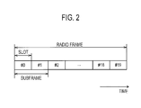
- Fig. 2 is a configuration diagram of a radio frame used in the LTE system 1.
- the LTE system 1 employs OFDMA (Orthogonal Frequency Division Multiplexing Access) in a downlink (DL) and SC-FDMA (Single Carrier Frequency Division Multiple Access) in an uplink (UL).
- OFDMA Orthogonal Frequency Division Multiplexing Access
- SC-FDMA Single Carrier Frequency Division Multiple Access
- the radio frame includes 10 subframes arranged in a time direction, wherein each subframe includes two slots arranged in the time direction. Each subframe has a length of 1 ms and each slot has a length of 0.5 ms.
- Each subframe includes a plurality of resource blocks (RBs) in a frequency direction, and a plurality of symbols in the time direction.
- RBs resource blocks
- Each resource block includes 12 continuous subcarriers and configures one unit when a frequency and time resource is assigned to the UE.
- Each symbol is provided at a head thereof with a guard interval called a cyclic prefix (CP).
- CP cyclic prefix
- an interval of several symbols at the head of each subframe is a control region mainly used as a physical downlink control channel (PDCCH). Furthermore, a remaining interval of each subframe is a data region mainly used as a physical downlink shared channel (PDSCH).
- PDCH physical downlink control channel
- PDSCH physical downlink shared channel
- the PDCCH carries a control signal.
- the control signal for example, includes uplink SI (Scheduling Information), downlink SI, and a TPC bit.
- the uplink SI indicates the assignment of an uplink frequency and time resource and the downlink SI indicates the assignment of a downlink frequency and time resource.
- the TPC bit is a signal for instructing increase or decrease in uplink transmission power.
- the PDSCH carries a control signal and/or user data.
- a downlink data region may be assigned only to the user data, or assigned such that the user data and the control signal are multiplexed.
- acknowledgement (ACK)/nonacknowledgement (NACK) is carried through a physical HARQ indicator channel (PHICH) .
- the ACK/NACK indicates whether decoding of a signal transmitted through an uplink physical channel (for example, PUSCH) is succeeded.
- both end portions in the frequency direction of each subframe are control regions mainly used as a physical uplink control channel (PUCCH). Furthermore, the center portion in the frequency direction of each subframe is a data region mainly used as a physical uplink shared channel (PUSCH).
- PUCCH physical uplink control channel
- PUSCH physical uplink shared channel
- the PUCCH carries a control signal.
- the control signal for example, includes CQI (Channel Quality Indicator), PMI (Precoding Matrix Indicator), RI (Rank Indicator), SR (Scheduling Request), and ACK/NACK.
- the CQI indicates a modulation scheme and coding rate (MCS) preferred to be used in the downlink, based on downlink channel quality.
- MCS modulation scheme and coding rate
- the CQI corresponds to channel quality information.
- the PMI indicates a precoder matrix (PM) preferred to be used in the downlink.
- the PMI indicates a precoder matrix in which a beam is directed toward UE serving as a transmission source of the PMI.
- the PMI corresponds to precoder matrix information.
- the RI indicates the number of layers (the number of streams) preferred to be used in the downlink.
- the SR is a signal for requesting the assignment of an uplink frequency and time resource (an uplink resource block).
- the ACK/NACK indicates whether decoding of a signal transmitted through a downlink physical channel (for example, PDSCH) is succeeded.
- the PUSCH is a physical channel for carrying a control signal and/or user data.
- an uplink data region may be assigned only to the user data, or assigned such that the user data and the control signal are multiplexed.
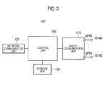
- Fig. 3 is a block diagram of the eNB.
- the eNB includes a plurality of antenna elements 101#0 to 101#3, a radio communication unit 110, a network communication unit 120, a storage unit 130, and a control unit 140.
- the antenna elements 101#0 to 101#3 are connected to antenna ports AP #0 to AP #3, respectively.
- the number of antenna ports AP is four.
- the number of antenna ports AP may be two or eight.
- one antenna element 101 is connected to one antenna port AP.
- two or more antenna elements 101 may be connected to one antenna port AP.
- the radio communication unit 110 performs radio communication through a plurality of antenna ports AP (a plurality of antenna elements 101). At the time of transmission, the radio communication unit 110 performs signal processing for a baseband signal, performs up-converting, amplification and the like for the processed signal, and then transmits a radio signal. At the time of reception, the radio communication unit 110 performs amplification, down-converting and the like for a received signal, performs signal processing for a baseband signal, and then outputs the processed signal to the control unit 140.
- the radio communication unit 110 transmits, to each antenna port AP, a cell-specific reference signal and/or a CSI reference signal (hereinafter, simply referred to as a "reference signal (RS)”) that is used in measurement, demodulation and the like in the UE. Since the reference signals transmitted from the antenna ports AP are different from one another, the UE is able to perform measurement and the like for each antenna port AP.
- RS reference signal
- the radio communication unit 110 transmits a downlink signal (a control signal and/or user data), which was precoded using a precoder matrix, through the plurality of antenna ports AP, thereby controlling a directional pattern, for example, forming a beam or a null.
- the radio communication unit 110 may support closed-loop spatial multiplexing, in which a plurality of data streams (layers) are transmitted in a parallel manner through the same frequency and time resource (resource block), on the basis of PMI and RI fed back from the UE.
- the closed-loop spatial multiplexing is SU-MIMO for a single user (SU) and MU-MIMO for multiple users (MU).
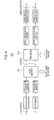
- Fig. 4 is a block diagram of the radio communication unit 110 for performing spatial multiplexing. Details of each block are disclosed in 3GPP TS 36.211. However, an overview of each block will be described herein. As illustrated in Fig. 4 , one or two codewords to be transmitted through a physical channel are scrambled, are modulated into a modulation symbol, and then are mapped to a plurality of layers by a layer map 111. The codeword is an error correction data unit. The number of layers is determined on the basis of RI fed back from the UE.
- the network communication unit 120 communicates with the EPC using the S1 interface. Furthermore, the network communication unit 120 performs communication (inter-base station communication) with adjacent eNB using the X2 interface.
- the storage unit 130 is configured using a memory and the like and stores various types of information used for control and the like by the control unit 140.
- the control unit 140 is configured using a processor and the like, and controls various functions of the eNB.
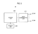
- Fig. 5 is a block diagram of the UE.
- the UE includes a plurality of antenna elements 201#1 to 201#n, a radio communication unit 210, a storage unit 220, and a control unit 230.
- the UE may include a user interface unit, a battery and the like.
- the radio communication unit 210 performs radio communication through the plurality of antenna elements 201.
- the radio communication unit 210 performs signal processing for a baseband signal, performs up-converting, amplification and the like for the processed signal, and then transmits a radio signal.
- the radio communication unit 210 performs amplification, down-converting and the like for a received signal, performs signal processing for a baseband signal, and then outputs the processed signal to the control unit 230.
- the radio communication unit 210 When the closed-loop spatial multiplexing is performed, the radio communication unit 210 generates channel state information (CSI) on the basis of the reference signal received from the eNB, and feeds back the channel state information to the eNB.
- the channel state information includes CQI, PMI, and RI.
- the radio communication unit 210 selects, according to a predetermined rule, an appropriate precoder matrix from candidates (code books) of precoder matrices determined in advance, and feeds back an index of the selected precoder matrix as PMI.
- the radio communication unit 210 performs decoding (MIMO decoding) and the like for a downlink signal received from the eNB, on the basis of the reference signal received from the eNB or TPMI (Transmitted PMI) notified from the eNB.
- the TPMI is information indicating a precoder matrix used when the eNB transmits the downlink signal, and corresponds to transmission precoder matrix information.
- the storage unit 220 is configured using a memory and the like and stores various types of information used for control and the like by the control unit 230.
- the control unit 230 is configured using a processor and the like, and controls various functions of the UE.
- the eNB and the UE support CB (Coordinated Beamforming)-CoMP (Coordinated Multi-Point).
- an antenna group in the same place is positioned as one "points" and a plurality of points communicate with the UE in cooperation with one another.
- a point group performing cooperative communication with the UE is called a CoMP cooperation set.
- the CB-CoMP indicates a scheme in which only one point holds data for the downlink, and a plurality of points perform beamforming in cooperation with one another.
- the CoMP cooperation set includes a plurality of eNBs.
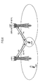
- Fig. 6 and Fig. 7 are diagrams illustrating operation environments of the eNB and the UE according to the present embodiment.
- a UE #1 performs communication by employing an eNB #1 as a serving cell
- a UE #2 performs communication by employing an eNB #2 as a serving cell
- the eNB #1 and the eNB #2 perform the CB-CoMP with the UE #1.
- the eNB #1 directs a beam toward the UE #1 subordinate to the eNB #1.
- the eNB #2 directs a null toward the UE #1 subordinate to the eNB #1 while directing a beam toward the UE #2 subordinate to the eNB #2.
- the UE #1 feeds back, to the eNB #1, PMI indicating a precoder matrix, in which a beam is directed toward the UE #1, on the basis of a reference signal received from the eNB #1.
- the UE #1 feeds back, to the eNB #2, Best Companion PMI (hereinafter, referred to as "BC-PMI") indicating a precoder matrix, in which a null is directed toward the UE #1, on the basis of a reference signal received from the eNB #2.
- BC-PMI Best Companion PMI
- the BC-PMI may be directly fed back from the UE #1 to the eNB #2.
- the BC-PMI may be indirectly fed back from the UE #1 to the eNB #2 via the eNB #1.
- the UE #2 may feedback, to the eNB #2, PMI indicating a precoder matrix, in which a beam is directed toward the UE #2, on the basis of the reference signal received from the eNB #2.
- the eNB #1 performs precoding using the precoder matrix indicated by the PMI fed back from the UE #1, thereby transmitting a downlink signal to the UE #1 in a directional pattern in which a beam is directed toward the UE #1.
- the eNB #2 performs precoding using the precoder matrix indicated by the BC-PMI fed back from the UE #1, thereby transmitting a downlink signal to the UE #2 in a directional pattern in which a null is directed toward the UE #1.
- the eNB #2 is not able to use a precoder matrix capable of achieving such high accuracy. As a consequence, it is difficult to reliably perform the CB-CoMP.
- the UE #1 selects an optimal precoder matrix from candidates (code books) of a precoder matrix determined in advance such that a null is directed toward the UE #1, and acquires BC-PMI indicating the selected precoder matrix.
- the BC-PMI corresponds to precoder matrix information.
- the UE #1 calculates a correction value for finely adjusting the precoder matrix indicated by the BC-PMI, and acquires PAI (Precoding Adjustment Indicator) indicating the calculated correction value.
- the PAI corresponds to correction value information.
- the UE #1 feeds back the acquired BC-PMI and PAI to the eNB #2.
- the BC-PMI and the PAI may be directly fed back from the UE #1 to the eNB #2.
- the BC-PMI and the PAI may be indirectly fed back from the UE #1 to the eNB #2 via the eNB #1.
- the PAI may be simultaneously fed back as additional information of the BC-PMI, or the PAI may be fed back after the BC-PMI is fed back.
- the PAI may not be fed back.
- the eNB #2 (or the eNB #1) may instruct the UE #1 to feed back the PAI.
- the eNB #2 reflects (multiplies) a correction value, which is indicated by the PAI notified from the UE #1, in (by) a precoder matrix indicated by the BC-PMI fed back from the UE #1, thereby correcting the precoder matrix. Then, the eNB #2 applies the corrected precoder matrix to transmission to the UE #2.
- the UE #1 increases resolution of the correction value indicated by the PAI at every feedback of the PAI. For example, the UE #1 increases the resolution of the correction value indicated by the PAI as with ⁇ /4 in the first time and ⁇ /8 in the second time. However, after predetermined resolution is reached, the UE #1 may stop increasing the resolution, that is, may limit the resolution.
- the PAI may include information on the resolution of the correction value indicated by the PAI. For example, in the case where a field for storing the information on the resolution is provided in the PAI, the resolution may be defined as ⁇ /4 if the field has a value of "0" and defined as ⁇ /8 if the field has a value of "1".
- the eNB #2 When the PAI is fed back from the UE #1 a plural number of times, the eNB #2 accumulates a correction value indicated by the PAI to acquire an accumulated correction value (hereinafter, referred to as an "accumulated PAI correction value") every time the PAI is received. Then, the eNB #2 determines a precoder matrix, which is applied to transmission of a downlink signal to the UE #2, in response to the fed-back BC-PMI and the accumulated PAI correction value. Specifically, the eNB #2 reflects the accumulated PAI correction value in the precoder matrix indicated by the fed-back BC-PMI, thereby correcting the precoder matrix.
- the eNB #2 When there is a change in the BC-PMI that is fed back, the eNB #2 resets the accumulated PAI. In other words, the eNB #2 continues to accumulate the PAI until there is a change in (a value of) the BC-PMI that is fed back.
- the eNB #2 transmits a downlink signal using the precoder matrix after the accumulated correction, thereby appropriately performing null steering in the CB-CoMPO.
- Fig. 8 is a diagram for explaining a detailed example of operations of the UE #1 and the eNB #2 according to the present embodiment.
- the UE #1 feeds back BC-PMI "1" to the eNB #2. Furthermore, in a precoder matrix indicated by the BC-PMI "1", a weight corresponding to the antenna port AP #0 of the eNB #2 is "1/2", a weight corresponding to the antenna port AP #1 is "j/2”, a weight corresponding to the antenna port AP #2 is "-1/2", and a weight corresponding to the antenna port AP #3 is "-j/2".
- the UE #1 feeds back PAI for correcting (finely adjusting) the BC-PMI to the eNB #2.
- a correction value corresponding to the antenna port AP #0 of the eNB #2 is "0”
- a correction value corresponding to the antenna port AP #1 is "0”
- a weight corresponding to the antenna port AP #2 is " (1-j) / ⁇ 2”
- a weight corresponding to the antenna port AP #3 is "(1+j)/ ⁇ 2".
- the weight corresponding to the antenna port AP #0 since the weight corresponding to the antenna port AP #0 has been fixedly set, the weight corresponding to the antenna port AP #0 is not corrected.
- the eNB #2 corrects the precoder matrix indicated by the BC-PMI fed back from the UE #1 using the correction value indicated by the PAI fed back from the UE #1.
- the weight corresponding to the antenna port AP #2 is corrected from "-1/2" to "(-1+j)/2 ⁇ 2" and the weight corresponding to the antenna port AP #3 is corrected from "-j/2" to "(1-j)/2 ⁇ 2".
- the eNB #2 determines to apply the corrected precoder matrix (PM) to transmission of a downlink signal to the UE #2. Then, the eNB #2 transmits a downlink signal to the UE #2 using the determined precoder matrix.
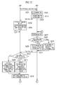
- Fig. 9 is a sequence diagram illustrating a detailed example of an operation sequence of the UE #1 and the eNB #2 according to the present embodiment.
- step S101 the eNB #2 (or the eNB #1) instructs the UE #1 to start to feed back PAI in response to the start of CB-CoMP.
- step S102 the UE #1 determines BC-PMI and PAI to be fed back to the eNB #2.
- step S103 the UE #1 feeds back the determined BC-PMI and PAI to the eNB #2.
- step S104 the eNB #2 determines a precoder matrix, which is applied to transmission of a downlink signal to the UE #2, in response to the BC-PMI and the PAI from the UE #1.
- step S105 the eNB #2 transmits a downlink signal to the UE #2 using the determined precoder matrix.
- step S106 the UE #1 determines BC-PMI to be fed back to the eNB #2.
- step S107 the UE #1 confirms whether BC-PMI, which is fed back this time, is equal to BC-PMI that was fed back previous time.
- the UE #1 determines PAI of this time such that resolution of a correction value is improved than before, in step S108.
- the UE #1 determines the PAI of this time such that the correction value has a default resolution in step S109.
- step S110 the UE #1 feeds back the determined BC-PMI and PAI to the eNB #2.
- step S111 the eNB #2 confirms whether the BC-PMI fed back this time is equal to the BC-PMI fed back previous time.
- the eNB #2 When the BC-PMI fed back this time is equal to the BC-PMI fed back previous time (step S111; YES), the eNB #2 accumulates a correction value indicated by the PAI fed back this time to a correction value indicated by the PAI fed back previous time, in step S112. Then, the eNB #2 corrects a precoder matrix indicated by the BC-PMI using an accumulated PAI correction value.
- the eNB #2 initializes (resets) the accumulated PAI correction value in step S113. Then, the eNB #2 corrects a precoder matrix indicated by the BC-PMI using the correction value indicated by the PAI fed back this time.
- step S114 the eNB #2 transmits a downlink signal to the UE #2 using the corrected precoder matrix. Then, the procedure returns to the step S106.
- the LTE system 1 includes the eNB #2 configured to transmit a downlink signal precoded by using a precoder matrix through the plurality of antenna ports AP, and the UE #1 configured to feedback, to the eNB #2, BC-PMI (precoder matrix information) indicating a precoder matrix preferably used in the downlink.
- BC-PMI precoder matrix information
- PAI correction value information
- the eNB #2 is able to correct BC-PMI (specifically, a precoder matrix indicated by the BC-PMI), which is fed back, using the PAI that is fed back, thereby accurately directing a null toward the UE #1.
- BC-PMI specifically, a precoder matrix indicated by the BC-PMI
- the eNB #2 instructs the UE #1 to notify the PAI.
- the UE #1 feeds back the PAI in response to an instruction from the eNB #2 (or the eNB #1).
- the UE #1 increases resolution of the PAI that is fed back.
- the PAI may include information indicating the resolution of the PAI.
- the eNB #2 accumulates the PAI every time the PAI is received.
- the eNB #2 determines a precoder matrix, which is applied to transmission of a downlink signal to the UE #2, in response to the BC-PMI fed back from the UE #1 and the accumulated PAI.
- the eNB #2 resets the accumulated PAI.
- the present embodiment is an embodiment in which the present invention is applied to MU-MIMO.
- Fig. 10 and Fig. 11 are diagrams illustrating operation environments of the eNB and the UE according to the present embodiment.
- the eNB performs the closed-loop spatial communication with two UEs (UE #1 and UE #2). That is, the eNB assigns the same frequency and time resource (resource block) to the UE #1 and UE #2 and performs the MU-MIMO.
- the UE #1 feeds back PMI to the eNB on the basis of a reference signal received from the eNB, wherein the PMI indicates a precoder matrix in which a beam is directed toward the UE #1.
- the UE #2 feeds back PMI to the eNB on the basis of the reference signal received from the eNB, wherein the PMI indicates a precoder matrix in which a beam is directed toward the UE #2.
- a description will be provided for a case where the PMI is fed back in the MU-MIMO.
- BC-PMI may be fed back.
- the eNB performs precoding using a precoder matrix indicated by the PMI fed back from the UE #1, thereby transmitting a downlink signal to the UE #1 in a directional pattern in which a beam is directed toward the UE #1. Furthermore, the eNB performs precoding using a precoder matrix indicated by the PMI fed back from the UE #2, thereby transmitting a downlink signal to the UE #2 in a directional pattern in which a beam is directed toward the UE #2.
- the MU-MIMO when UEs to be multiplexed with each other are adjacent to each other, it is preferable to improve the accuracy by which a beam is directed toward each UE.
- excellent beamforming is performed in the MU-MIMO as follows.
- each UE selects an optimal precoder matrix from candidates (code books) of a precoder matrix determined in advance such that a beam is directed toward each UE, and acquires PMI indicating the selected precoder matrix.
- the PMI corresponds to precoder matrix information.
- each UE calculates a correction value for finely adjusting the precoder matrix indicated by the PMI, and acquires PAI indicating the calculated correction value.
- the calculated correction value an immediate value
- the PAI is used as an index of the calculated correction value in the present embodiment.
- each UE feeds back the acquired PMI and PAI to the eNB.
- the PAI may be simultaneously fed back as additional information of the PMI, or the PAI may be fed back after the PMI is fed back.
- the PAI may not be fed back.
- the eNB may instruct each UE to feed back the PAI.
- the eNB reflects (multiplies) a correction value, which is indicated by the PAI, in (by) a precoder matrix indicated by the PMI fed back from each UE, thereby correcting the precoder matrix. Then, the eNB applies the corrected precoder matrix to transmission.
- each UE increases resolution of the correction value indicated by the PAI at every feedback of the PAI.
- the UE #1 increases the resolution of the correction value indicated by the PAI as with ⁇ /4 in the first time and ⁇ /8 in the second time.
- the UE #1 may stop increasing the resolution, that is, may limit the resolution.
- the PAI may include information on the resolution of the correction value indicated by the PAI. For example, in the case where a field for storing the information on the resolution is provided in the PAI, the resolution may be defined as + ⁇ /4 if the field has a value of "0" and defined as ⁇ /8 if the field has a value of "1".
- the eNB When the PAI is fed back from each UE a plural number of times, the eNB accumulates, for each UE, a correction value indicated by the PAI to acquire an accumulated correction value (hereinafter, referred to as an "accumulated PAI correction value") every time the PAI is received. Then, the eNB determines a precoder matrix, which is applied to transmission of a downlink signal, in response to the fed-back PMI and the accumulated PAI correction value. Specifically, the eNB reflects the accumulated PAI correction value in the precoder matrix indicated by the fed-back PMI, thereby correcting the precoder matrix.
- the eNB When there is a change in the PMI that is fed back, the eNB resets the accumulated PAI. In other words, the eNB continues to accumulate the PAI until there is a change in (a value of) the PMI that is fed back.
- the eNB transmits a downlink signal using the precoder matrix after the accumulated correction, thereby appropriately performing beamforming in the MU-MIMO.
- each UE when notifying the eNB of the PAI, each UE corrects CQI to be fed back to the eNB, in expectation of quality improvement due to the correction using the PAI.
- MCS modulation scheme and coding rate
- the eNB should notify the UE of PMI, which corresponds to a precoder matrix used by the eNB in transmission, as TPMI. This is because since no precoding is performed for CRS, the UE is not able to designate a state (a precoder matrix) of precoding on the basis of the CRS, and to decode precoded data.
- the eNB selects PMI corresponding to a precoder matrix before the change as TPMI, and if the PMI corresponding to the corrected precoder matrix has been defined, the eNB selects the PMI as TPMI.
- the eNB needs not to notify the TPMI. This is because since precoding is performed for the DMRS similarly to data, the UE is able to decode data without considering an actually used precoder matrix.
- DMRS Demonulation Reference Signal/UE specific Reference Signal
- Fig. 12 is a sequence diagram illustrating a detailed example of an operation sequence of the UE #1 and the eNB according to the present embodiment.
- step S201 the eNB instructs the UE #1 to start to feed back PAI in response to the start of MU-MIMO.
- step S202 the UE #1 determines PMI to be fed back to the eNB.
- step S203 the UE #1 determines PAI and CQI to be fed back to the eNB. Furthermore, the UE #1 determines CQI, which is expected to be improved, by the PAI, from the original CQI (that is, CQI corresponding to the determined PMI), as CQI to be fed back.
- step S204 the UE #1 feeds back the determined PMI, PAI, and CQI to the eNB.
- step S205 the eNB determines a corrected precoder matrix, which is applied to transmission of a downlink signal to the UE #1, in response to the PMI and the PAI fed back from the UE #1.
- step S206 the eNB. transmits a downlink signal to the UE #1 using the corrected precoder matrix and MCS indicated by the CQI fed back from the UE #1.
- step S207 the UE #1 determines PMI to be fed back to the eNB.
- step S208 the UE #1 confirms whether PMI, which is fed back this time, is equal to PMI that was fed back previous time.
- the UE #1 determines PAI of this time such that resolution of a correction value is improved than before, in step S209. In this case, in consideration of the accumulated correction by the PAI, the UE #1 determines CQI, which is expected to be improved by the accumulated correction, as CQI to be fed back.
- the UE #1 determines the PAI of this time such that the correction value has a default resolution in step S210. In this case, the UE #1 determines CQI, which is expected to be improved, by the PAI, from the original CQI (that is, CQI corresponding to the determined PMI), as CQI to be fed back.
- step S211 the UE #1 feeds back the determined PMI, PAI, and CQI to the eNB.
- step S212 the eNB confirms whether the PMI fed back this time is equal to the PMI fed back previous time.
- the eNB When the PMI fed back this time is equal to the PMI fed back previous time (step S212; YES), the eNB accumulates a correction value indicated by the PAI fed back this time to a correction value indicated by the PAI fed back previous time, in step S213. Then, the eNB corrects a precoder matrix indicated by the PMI using an accumulated correction value.
- the eNB initializes (resets) the accumulated PAI correction value in step S214. Then, the eNB corrects a precoder matrix indicated by the PMI using the correction value indicated by the PAI fed back this time.
- step S215 the eNB transmits a downlink signal to the UE #1 using the corrected precoder matrix and the MCS indicated by the CQI fed back from the UE #1.
- the UE #1 when feeding back the PMI or after feeding back the PMI, the UE #1 feeds back PAI (correction value information) for correcting the PMI to the eNB.
- PAI correction value information
- the eNB is able to correct PMI (specifically, a precoder matrix indicated by the PMI), which is fed back, using the PAI that is fed back, thereby accurately directing a beam toward the UE #1.
- PMI specifically, a precoder matrix indicated by the PMI
- the eNB instructs the UE #1 to notify the PAI.
- the UE #1 feeds back the PAI in response to an instruction from the eNB.
- the UE #1 increases resolution of the PAI that is fed back.
- the PAI may include information indicating the resolution of the PAI.
- the eNB accumulates the PAI every time the PAI is received.
- the eNB determines a precoder matrix, which is applied to transmission of a downlink signal to the UE #1, in response to the PMI fed back from the UE #1 and the accumulated PAI.
- the eNB resets the accumulated PAI.
- the aforementioned first embodiment to fourth embodiment can be performed separately and independently, and can be performed through a combination thereof.
- the present invention can be applied to an operation environment in which both MU-MIMO and CB-CoMP are used.
- the present invention is useful in mobile communication fields .
Landscapes
- Engineering & Computer Science (AREA)
- Computer Networks & Wireless Communication (AREA)
- Signal Processing (AREA)
- Quality & Reliability (AREA)
- Physics & Mathematics (AREA)
- Mathematical Physics (AREA)
- Mobile Radio Communication Systems (AREA)
- Radio Transmission System (AREA)
Abstract
Description
- The present invention relates to a communication control method, a user terminal, and a base station, which deal with precoder matrix information.
- 3GPP (3rd Generation Partnership Project), which is a project aiming to standardize a mobile communication system, supports a multi-antenna transmission technology, in which a base station directs a beam toward a specific user terminal while directing a null toward another user terminal (see, for example, Non Patent Document 1).
- In order to realize such a multi-antenna transmission technology using an FDD scheme, each of a plurality of user terminals feeds back precoder matrix information, which indicates a precoder matrix preferred to be used in a downlink, to a base station.
- The base station precodes a downlink signal using the precoder matrix based on the precoder matrix information fed back from each user terminal. Then, the base station transmits the precoded downlink signal through a plurality of antenna ports (a plurality of feeding points). The precoder matrix includes a plurality of precoder matrix elements (a plurality of weights) corresponding to the plurality of antenna ports.
- Non-patent Document 1: 3GPP technology specifications "TS 36.300 V11. 0. 0" December, 2011
- However, since resolution of precoder matrix information defined in the current specifications is insufficient, there is a problem that it is difficult for a base station to direct a beam toward a specific user terminal while accurately directing a null toward another user terminal.
- Therefore, an object of the present invention is to provide a communication control method in which a base station is able to appropriately direct a beam/a null toward a user terminal; a user terminal; and a base station.
- In order solve the problems described above, the present invention includes following features.
- A communication control method of the present invention is applied to a mobile communication system including a base station that transmits a downlink signal through a plurality of antenna ports, and a user terminal that feeds back precoder matrix information to the base station, the downlink signal being precoded by using a precoder matrix, the precoder matrix information being indicating a precoder matrix preferably used in a downlink. The communication control method comprises: a step A of feeding back, by the user terminal, correction value information for correcting the precoder matrix information to the base station when the precoder matrix information is fed back or after the precoder matrix information is fed back.
- The communication control method may further comprises: a step B of instructing, by the base station, the user terminal to notify the correction value information, wherein in the step A, the user terminal feeds back the correction value information in response to an instruction from the base station in the step B.
- In the step A, the user terminal may increase resolution of the correction value information that is fed back, every time the correction value information is fed back.
- The correction value information may include information indicating the resolution of the correction value information.
- The communication control method may further comprises : a step C of accumulating, by the base station, the correction value information every time the correction value information is received in a case where the correction value information is fed back from the user terminal a plural number of times.
- The communication control method may further comprises : a step D of determining, by the base station, a precoder matrix to be applied to transmission of a downlink signal, based on the precoder matrix information fed back from the user terminal, and accumulated correction value information obtained in the step C.
- The communication control method may further comprises: a step E of resetting the accumulated correction value information obtained in the step C when there is a change in the precoder matrix information that is fed back.
- The communication control method may further comprises: a step F of feeding back, by the user terminal, channel quality information to the base station, the channel quality information indicating a modulation scheme and coding rate preferably used in the downlink, wherein in the step F, the user terminal corrects the channel quality information that is fed back, when feeding back the correction value information.
- The precoder matrix information may indicate a precoder matrix in which a null is directed toward the user terminal.
- The precoder matrix information may indicate a precoder matrix in which a beam is directed toward the user terminal.
- A user terminal of the present invention feeds back precoder matrix information to a base station that transmits a downlink signal through a plurality of antenna ports, the precoder matrix information being indicating a precoder matrix preferably used in a downlink, the downlink signal being precoded by using a precoder matrix. The user terminal comprises: a control unit that feeds back correction value information for correcting the precoder matrix information to the base station when the precoder matrix information is fed back or after the precoder matrix information is fed back.
- A base station of the present invention transmits a downlink signal through a plurality of antenna ports, the downlink signal being precoded using a precoder matrix. The base station comprises: a first reception unit that receives precoder matrix information that is fed back from a user terminal; and a second reception unit that receives correction value information that is fed back from the user terminal, when the precoder matrix information is fed back or after the precoder matrix information is fed back, wherein the precoder matrix information indicates a precoder matrix preferably used in a downlink, and the correction value information includes information for correcting the precoder matrix information.
-
-
Fig. 1 is a configuration diagram of an LTE system according to a first embodiment and a second embodiment. -
Fig. 2 is a configuration diagram of a radio frame used in the LATE system according to the first embodiment and the second embodiment. -
Fig. 3 is a block diagram of eNB according to the first embodiment and the second embodiment. -
Fig. 4 is a block diagram of a radio communication unit for performing spatial multiplexing. -
Fig. 5 is a block diagram of UE according to the first embodiment and the second embodiment. -
Fig. 6 is a diagram illustrating an operation environment of the eNB and the UE according to the first embodiment (part 1). -
Fig. 7 is a diagram illustrating an operation environment of the eNB and the UE according to the first embodiment (part 2). -
Fig. 8 is a diagram for explaining a detailed example of operations of the eNB and the UE according to the first embodiment. -
Fig. 9 is a sequence diagram illustrating a detailed example of an operation sequence of the eNB and the UE according to the first embodiment. -
Fig. 10 is a diagram illustrating an operation environment of the eNB and the UE according to the second embodiment (part 1) . -
Fig. 11 is a diagram illustrating an operation environment of the eNB and the UE according to the second embodiment (part 2) . -
Fig. 12 is a sequence diagram illustrating a detailed example of an operation sequence of the eNB and the UE according to the second embodiment. - Hereinafter, embodiments of the present invention will be described with reference to the accompanying drawings. Note that in the following drawing according to the embodiments, identical or similar symbols are assigned to identical or similar portions.
- A communication control method according to an embodiment is applied to a mobile communication system including a base station that transmits a downlink signal through a plurality of antenna ports, and a user terminal that feeds back precoder matrix information to the base station, the downlink signal being precoded by using a precoder matrix, the precoder matrix information being indicating a precoder matrix preferably used in a downlink.
- The communication control method according to the embodiment comprises : a step of feeding back, by the user terminal, correction value information for correcting the precoder matrix information to the base station when the precoder matrix information is fed back or after the precoder matrix information is fed back.
- In this way, the base station is able to correct precoder matrix information (specifically, a precoder matrix indicated by the precoder matrix information), which is fed back, using correction value information that is fed back, thereby accurately directing a beam/a null toward the user terminal.
- Hereinafter, a first embodiment will be described.
- First, the overview of an LTE system will be described.
Fig. 1 is a configuration diagram of the LTE system. - As illustrated in
Fig. 1 , anLTE system 1 includes UE (User Equipment), E-UTRAN (Evolved-UMTS Terrestrial Radio Access Network), and EPC (Evolved Packet Core). - The UE is a mobile radio communication device and corresponds to a user terminal. The UE is a mobile radio communication device, and performs radio communication with a cell (called a "serving cell"), which established a connection, in a connected state corresponding to a state during a connection.
- The E-UTRAN includes a plurality of eNBs (evolved Node-B) . The eNB is a stationary radio communication device that performs radio communication with the UE, and corresponds to a base station. Each eNB configures one cell or a plurality of cells. The eNB, for example, has a radio resource management (RRM) function, a routing function of user data, and a measurement control function for mobility control and scheduling.
- The EPC includes MME (Mobility Management Entity) and S-GW (Serving-Gateway). The EPC corresponds to a core network. The MME is a network entity that performs various types of mobility control and the like for the UE, and corresponds to a control station. The S-GW is a network entity that performs transmission control of user data, and corresponds to a switching center.
- The eNBs are connected to one another through an X2 interface. Furthermore, the eNBs are connected to the MME and the S-GW through S1 interfaces.
-
Fig. 2 is a configuration diagram of a radio frame used in theLTE system 1. TheLTE system 1 employs OFDMA (Orthogonal Frequency Division Multiplexing Access) in a downlink (DL) and SC-FDMA (Single Carrier Frequency Division Multiple Access) in an uplink (UL). - As illustrated in
Fig. 2 , the radio frame includes 10 subframes arranged in a time direction, wherein each subframe includes two slots arranged in the time direction. Each subframe has a length of 1 ms and each slot has a length of 0.5 ms. Each subframe includes a plurality of resource blocks (RBs) in a frequency direction, and a plurality of symbols in the time direction. Each resource block includes 12 continuous subcarriers and configures one unit when a frequency and time resource is assigned to the UE. Each symbol is provided at a head thereof with a guard interval called a cyclic prefix (CP). - In the downlink, an interval of several symbols at the head of each subframe is a control region mainly used as a physical downlink control channel (PDCCH). Furthermore, a remaining interval of each subframe is a data region mainly used as a physical downlink shared channel (PDSCH).
- The PDCCH carries a control signal. The control signal, for example, includes uplink SI (Scheduling Information), downlink SI, and a TPC bit. The uplink SI indicates the assignment of an uplink frequency and time resource and the downlink SI indicates the assignment of a downlink frequency and time resource. The TPC bit is a signal for instructing increase or decrease in uplink transmission power.
- The PDSCH carries a control signal and/or user data. For example, a downlink data region may be assigned only to the user data, or assigned such that the user data and the control signal are multiplexed.
- Furthermore, acknowledgement (ACK)/nonacknowledgement (NACK) is carried through a physical HARQ indicator channel (PHICH) . The ACK/NACK indicates whether decoding of a signal transmitted through an uplink physical channel (for example, PUSCH) is succeeded.
- In the uplink (UL), both end portions in the frequency direction of each subframe are control regions mainly used as a physical uplink control channel (PUCCH). Furthermore, the center portion in the frequency direction of each subframe is a data region mainly used as a physical uplink shared channel (PUSCH).
- The PUCCH carries a control signal. The control signal, for example, includes CQI (Channel Quality Indicator), PMI (Precoding Matrix Indicator), RI (Rank Indicator), SR (Scheduling Request), and ACK/NACK.
- The CQI indicates a modulation scheme and coding rate (MCS) preferred to be used in the downlink, based on downlink channel quality. In the present embodiment, the CQI corresponds to channel quality information.
- The PMI indicates a precoder matrix (PM) preferred to be used in the downlink. Specifically, the PMI indicates a precoder matrix in which a beam is directed toward UE serving as a transmission source of the PMI. In the present embodiment, the PMI corresponds to precoder matrix information.
- The RI indicates the number of layers (the number of streams) preferred to be used in the downlink.
- The SR is a signal for requesting the assignment of an uplink frequency and time resource (an uplink resource block).
- The ACK/NACK indicates whether decoding of a signal transmitted through a downlink physical channel (for example, PDSCH) is succeeded.
- The PUSCH is a physical channel for carrying a control signal and/or user data. For example, an uplink data region may be assigned only to the user data, or assigned such that the user data and the control signal are multiplexed.
-
Fig. 3 is a block diagram of the eNB. - As illustrated in
Fig. 3 , the eNB includes a plurality ofantenna elements 101#0 to 101#3, aradio communication unit 110, anetwork communication unit 120, astorage unit 130, and acontrol unit 140. - The
antenna elements 101#0 to 101#3 are connected to antennaports AP # 0 toAP # 3, respectively. In addition, in the present embodiment, the number of antenna ports AP is four. However, the number of antenna ports AP may be two or eight. Furthermore, oneantenna element 101 is connected to one antenna port AP. However, two ormore antenna elements 101 may be connected to one antenna port AP. - The
radio communication unit 110 performs radio communication through a plurality of antenna ports AP (a plurality of antenna elements 101). At the time of transmission, theradio communication unit 110 performs signal processing for a baseband signal, performs up-converting, amplification and the like for the processed signal, and then transmits a radio signal. At the time of reception, theradio communication unit 110 performs amplification, down-converting and the like for a received signal, performs signal processing for a baseband signal, and then outputs the processed signal to thecontrol unit 140. - The
radio communication unit 110 transmits, to each antenna port AP, a cell-specific reference signal and/or a CSI reference signal (hereinafter, simply referred to as a "reference signal (RS)") that is used in measurement, demodulation and the like in the UE. Since the reference signals transmitted from the antenna ports AP are different from one another, the UE is able to perform measurement and the like for each antenna port AP. - The
radio communication unit 110 transmits a downlink signal (a control signal and/or user data), which was precoded using a precoder matrix, through the plurality of antenna ports AP, thereby controlling a directional pattern, for example, forming a beam or a null. - The
radio communication unit 110 may support closed-loop spatial multiplexing, in which a plurality of data streams (layers) are transmitted in a parallel manner through the same frequency and time resource (resource block), on the basis of PMI and RI fed back from the UE. The closed-loop spatial multiplexing is SU-MIMO for a single user (SU) and MU-MIMO for multiple users (MU). -
Fig. 4 is a block diagram of theradio communication unit 110 for performing spatial multiplexing. Details of each block are disclosed in 3GPP TS 36.211. However, an overview of each block will be described herein. As illustrated inFig. 4 , one or two codewords to be transmitted through a physical channel are scrambled, are modulated into a modulation symbol, and then are mapped to a plurality of layers by alayer map 111. The codeword is an error correction data unit. The number of layers is determined on the basis of RI fed back from the UE. - A
precoder 112 precedes a modulation symbol of each layer using a precoder matrix of each layer. The precoder matrix is determined on the basis of PMI fed back from the UE. The precoded modulation symbol is mapped to a resource element, is converted into an OFDM signal of a temporal domain, and is output to each antenna port AP. In addition, the resource element is a resource unit including one subcarrier and one symbol. - Returning to
Fig. 3 , thenetwork communication unit 120 communicates with the EPC using the S1 interface. Furthermore, thenetwork communication unit 120 performs communication (inter-base station communication) with adjacent eNB using the X2 interface. - The
storage unit 130 is configured using a memory and the like and stores various types of information used for control and the like by thecontrol unit 140. Thecontrol unit 140 is configured using a processor and the like, and controls various functions of the eNB. -
Fig. 5 is a block diagram of the UE. - As illustrated in
Fig. 5 , the UE includes a plurality ofantenna elements 201#1 to 201#n, aradio communication unit 210, astorage unit 220, and acontrol unit 230. The UE may include a user interface unit, a battery and the like. - For example, two or four
antenna elements 201 are provided. Theradio communication unit 210 performs radio communication through the plurality ofantenna elements 201. At the time of transmission, theradio communication unit 210 performs signal processing for a baseband signal, performs up-converting, amplification and the like for the processed signal, and then transmits a radio signal. At the time of reception, theradio communication unit 210 performs amplification, down-converting and the like for a received signal, performs signal processing for a baseband signal, and then outputs the processed signal to thecontrol unit 230. - When the closed-loop spatial multiplexing is performed, the
radio communication unit 210 generates channel state information (CSI) on the basis of the reference signal received from the eNB, and feeds back the channel state information to the eNB. The channel state information includes CQI, PMI, and RI. - The
radio communication unit 210 selects, according to a predetermined rule, an appropriate precoder matrix from candidates (code books) of precoder matrices determined in advance, and feeds back an index of the selected precoder matrix as PMI. - The
radio communication unit 210 performs decoding (MIMO decoding) and the like for a downlink signal received from the eNB, on the basis of the reference signal received from the eNB or TPMI (Transmitted PMI) notified from the eNB. The TPMI is information indicating a precoder matrix used when the eNB transmits the downlink signal, and corresponds to transmission precoder matrix information. - The
storage unit 220 is configured using a memory and the like and stores various types of information used for control and the like by thecontrol unit 230. Thecontrol unit 230 is configured using a processor and the like, and controls various functions of the UE. - In the present embodiment, the eNB and the UE support CB (Coordinated Beamforming)-CoMP (Coordinated Multi-Point).
- In the CoMP, an antenna group in the same place is positioned as one "points" and a plurality of points communicate with the UE in cooperation with one another. A point group performing cooperative communication with the UE is called a CoMP cooperation set.
- The CB-CoMP indicates a scheme in which only one point holds data for the downlink, and a plurality of points perform beamforming in cooperation with one another. In the present embodiment, the CoMP cooperation set includes a plurality of eNBs.
-
Fig. 6 andFig. 7 are diagrams illustrating operation environments of the eNB and the UE according to the present embodiment. - As illustrated in
Fig. 6 andFig. 7 , aUE # 1 performs communication by employing aneNB # 1 as a serving cell, and aUE # 2 performs communication by employing aneNB # 2 as a serving cell. TheeNB # 1 and theeNB # 2 perform the CB-CoMP with theUE # 1. Specifically, theeNB # 1 directs a beam toward theUE # 1 subordinate to theeNB # 1. TheeNB # 2 directs a null toward theUE # 1 subordinate to theeNB # 1 while directing a beam toward theUE # 2 subordinate to theeNB # 2. - As illustrated in
Fig. 6 , theUE # 1 feeds back, to theeNB # 1, PMI indicating a precoder matrix, in which a beam is directed toward theUE # 1, on the basis of a reference signal received from theeNB # 1. - Furthermore, the
UE # 1 feeds back, to theeNB # 2, Best Companion PMI (hereinafter, referred to as "BC-PMI") indicating a precoder matrix, in which a null is directed toward theUE # 1, on the basis of a reference signal received from theeNB # 2. - The BC-PMI may be directly fed back from the
UE # 1 to theeNB # 2. Alternatively, the BC-PMI may be indirectly fed back from theUE # 1 to theeNB # 2 via theeNB # 1. - The
UE # 2 may feedback, to theeNB # 2, PMI indicating a precoder matrix, in which a beam is directed toward theUE # 2, on the basis of the reference signal received from theeNB # 2. - As illustrated in
Fig. 7 , theeNB # 1 performs precoding using the precoder matrix indicated by the PMI fed back from theUE # 1, thereby transmitting a downlink signal to theUE # 1 in a directional pattern in which a beam is directed toward theUE # 1. - The
eNB # 2 performs precoding using the precoder matrix indicated by the BC-PMI fed back from theUE # 1, thereby transmitting a downlink signal to theUE # 2 in a directional pattern in which a null is directed toward theUE # 1. - However, since the precoding for directing a null requires very high accuracy but all possible values (indices) of the BC-PMI are limited, the
eNB # 2 is not able to use a precoder matrix capable of achieving such high accuracy. As a consequence, it is difficult to reliably perform the CB-CoMP. - In this regard, in the present embodiment, it is possible to reliably perform the CB-CoMP as follows.
- Firstly, the
UE # 1 selects an optimal precoder matrix from candidates (code books) of a precoder matrix determined in advance such that a null is directed toward theUE # 1, and acquires BC-PMI indicating the selected precoder matrix. In the present embodiment, the BC-PMI corresponds to precoder matrix information. - At this time, in order to increase the accuracy by which a null is directed toward the
UE # 1, theUE # 1 calculates a correction value for finely adjusting the precoder matrix indicated by the BC-PMI, and acquires PAI (Precoding Adjustment Indicator) indicating the calculated correction value. In the present embodiment, the PAI corresponds to correction value information. When the correction value (an immediate value) calculated by theUE # 1 is fed back, since overhead is increased, the PAI is used as an index of the correction value calculated by theUE # 1 in the present embodiment. - Then, the
UE # 1 feeds back the acquired BC-PMI and PAI to theeNB # 2. The BC-PMI and the PAI may be directly fed back from theUE # 1 to theeNB # 2. Alternatively, the BC-PMI and the PAI may be indirectly fed back from theUE # 1 to theeNB # 2 via theeNB # 1. Furthermore, the PAI may be simultaneously fed back as additional information of the BC-PMI, or the PAI may be fed back after the BC-PMI is fed back. - In addition, when no CB-CoMP is performed, the PAI may not be fed back. For example, when the CB-CoMP is performed, the eNB #2 (or the eNB #1) may instruct the
UE # 1 to feed back the PAI. - Secondly, the
eNB # 2 reflects (multiplies) a correction value, which is indicated by the PAI notified from theUE # 1, in (by) a precoder matrix indicated by the BC-PMI fed back from theUE # 1, thereby correcting the precoder matrix. Then, theeNB # 2 applies the corrected precoder matrix to transmission to theUE # 2. - In the present embodiment, the
UE # 1 increases resolution of the correction value indicated by the PAI at every feedback of the PAI. For example, theUE # 1 increases the resolution of the correction value indicated by the PAI as with ±π/4 in the first time and ±π/8 in the second time. However, after predetermined resolution is reached, theUE # 1 may stop increasing the resolution, that is, may limit the resolution. Furthermore, the PAI may include information on the resolution of the correction value indicated by the PAI. For example, in the case where a field for storing the information on the resolution is provided in the PAI, the resolution may be defined as ±π/4 if the field has a value of "0" and defined as ±π/8 if the field has a value of "1". - When the PAI is fed back from the UE #1 a plural number of times, the
eNB # 2 accumulates a correction value indicated by the PAI to acquire an accumulated correction value (hereinafter, referred to as an "accumulated PAI correction value") every time the PAI is received. Then, theeNB # 2 determines a precoder matrix, which is applied to transmission of a downlink signal to theUE # 2, in response to the fed-back BC-PMI and the accumulated PAI correction value. Specifically, theeNB # 2 reflects the accumulated PAI correction value in the precoder matrix indicated by the fed-back BC-PMI, thereby correcting the precoder matrix. - When there is a change in the BC-PMI that is fed back, the
eNB # 2 resets the accumulated PAI. In other words, theeNB # 2 continues to accumulate the PAI until there is a change in (a value of) the BC-PMI that is fed back. - In this way, the
eNB # 2 transmits a downlink signal using the precoder matrix after the accumulated correction, thereby appropriately performing null steering in the CB-CoMPO. -
Fig. 8 is a diagram for explaining a detailed example of operations of theUE # 1 and theeNB # 2 according to the present embodiment. - As illustrated in
Fig. 8 , theUE # 1 feeds back BC-PMI "1" to theeNB # 2. Furthermore, in a precoder matrix indicated by the BC-PMI "1", a weight corresponding to the antennaport AP # 0 of theeNB # 2 is "1/2", a weight corresponding to the antennaport AP # 1 is "j/2", a weight corresponding to the antennaport AP # 2 is "-1/2", and a weight corresponding to the antennaport AP # 3 is "-j/2". - When feeding back the BC-PMI to the
eNB # 2, theUE # 1 feeds back PAI for correcting (finely adjusting) the BC-PMI to theeNB # 2. In the example ofFig. 8 , in relation to a correction value indicated by the PAI, a correction value corresponding to the antennaport AP # 0 of theeNB # 2 is "0", a correction value corresponding to the antennaport AP # 1 is "0", a weight corresponding to the antennaport AP # 2 is " (1-j) /√2", and a weight corresponding to the antennaport AP # 3 is "(1+j)/√2". - In addition, in the precoder matrix, since the weight corresponding to the antenna
port AP # 0 has been fixedly set, the weight corresponding to the antennaport AP # 0 is not corrected. - The
eNB # 2 corrects the precoder matrix indicated by the BC-PMI fed back from theUE # 1 using the correction value indicated by the PAI fed back from theUE # 1. In the example ofFig. 8 , the weight corresponding to the antennaport AP # 2 is corrected from "-1/2" to "(-1+j)/2√2" and the weight corresponding to the antennaport AP # 3 is corrected from "-j/2" to "(1-j)/2√2". Next, theeNB # 2 determines to apply the corrected precoder matrix (PM) to transmission of a downlink signal to theUE # 2. Then, theeNB # 2 transmits a downlink signal to theUE # 2 using the determined precoder matrix. -
Fig. 9 is a sequence diagram illustrating a detailed example of an operation sequence of theUE # 1 and theeNB # 2 according to the present embodiment. - As illustrated in
Fig. 9 , in step S101, the eNB #2 (or the eNB #1) instructs theUE # 1 to start to feed back PAI in response to the start of CB-CoMP. - In step S102, the
UE # 1 determines BC-PMI and PAI to be fed back to theeNB # 2. - In step S103, the
UE # 1 feeds back the determined BC-PMI and PAI to theeNB # 2. - In step S104, the
eNB # 2 determines a precoder matrix, which is applied to transmission of a downlink signal to theUE # 2, in response to the BC-PMI and the PAI from theUE # 1. - In step S105, the
eNB # 2 transmits a downlink signal to theUE # 2 using the determined precoder matrix. - In step S106, the
UE # 1 determines BC-PMI to be fed back to theeNB # 2. - In step S107, the
UE # 1 confirms whether BC-PMI, which is fed back this time, is equal to BC-PMI that was fed back previous time. - When the BC-PMI, which is fed back this time, is equal to the BC-PMI that was fed back previous time (step S107; YES), the
UE # 1 determines PAI of this time such that resolution of a correction value is improved than before, in step S108. - On the other hand, when the BC-PMI, which is fed back this time, is different from the BC-PMI that was fed back previous time (step S107; NO), the
UE # 1 determines the PAI of this time such that the correction value has a default resolution in step S109. - In step S110, the
UE # 1 feeds back the determined BC-PMI and PAI to theeNB # 2. - In step S111, the
eNB # 2 confirms whether the BC-PMI fed back this time is equal to the BC-PMI fed back previous time. - When the BC-PMI fed back this time is equal to the BC-PMI fed back previous time (step S111; YES), the
eNB # 2 accumulates a correction value indicated by the PAI fed back this time to a correction value indicated by the PAI fed back previous time, in step S112. Then, theeNB # 2 corrects a precoder matrix indicated by the BC-PMI using an accumulated PAI correction value. - On the other hand, when the BC-PMI fed back this time is different from the BC-PMI fed back previous time (step S111; NO), the
eNB # 2 initializes (resets) the accumulated PAI correction value in step S113. Then, theeNB # 2 corrects a precoder matrix indicated by the BC-PMI using the correction value indicated by the PAI fed back this time. - In step S114, the
eNB # 2 transmits a downlink signal to theUE # 2 using the corrected precoder matrix. Then, the procedure returns to the step S106. - As described above, the
LTE system 1 includes theeNB # 2 configured to transmit a downlink signal precoded by using a precoder matrix through the plurality of antenna ports AP, and theUE # 1 configured to feedback, to theeNB # 2, BC-PMI (precoder matrix information) indicating a precoder matrix preferably used in the downlink. When feeding back the BC-PMI or after feeding back the BC-PMI, theUE # 1 feeds back PAI (correction value information) for correcting the BC-PMI to theeNB # 2. - In this way, the
eNB # 2 is able to correct BC-PMI (specifically, a precoder matrix indicated by the BC-PMI), which is fed back, using the PAI that is fed back, thereby accurately directing a null toward theUE # 1. - In the present embodiment, when the CB-CoMP is performed, the eNB #2 (or the eNB #1) instructs the
UE # 1 to notify the PAI. TheUE # 1 feeds back the PAI in response to an instruction from the eNB #2 (or the eNB #1). - In this way, since the PAI is fed back in the case where the PAI is necessary, but the PAI is not fed back in the case where the PAI is not necessary, it is possible to suppress an increase in overhead.
- In the present embodiment, at every feedback of the PAI, the
UE # 1 increases resolution of the PAI that is fed back. The PAI may include information indicating the resolution of the PAI. When the PAI is fed back from the UE #1 a plural number of times, theeNB # 2 accumulates the PAI every time the PAI is received. TheeNB # 2 determines a precoder matrix, which is applied to transmission of a downlink signal to theUE # 2, in response to the BC-PMI fed back from theUE # 1 and the accumulated PAI. When there is a change in the BC-PMI that is fed back, theeNB # 2 resets the accumulated PAI. - In this way, the accuracy by which a null is directed toward the
UE # 1 is sequentially improved until the BC-PMI is changed, so that it is possible to reliably perform the CB-CoMPO. - Hereinafter, a second embodiment will be described. The present embodiment is an embodiment in which the present invention is applied to MU-MIMO.
- In the present embodiment, differences from the first embodiment will be mainly described, and a description identical to that of the first embodiment will be appropriately omitted.
-
Fig. 10 andFig. 11 are diagrams illustrating operation environments of the eNB and the UE according to the present embodiment. - As illustrated in
Fig. 10 andFig. 11 , the eNB performs the closed-loop spatial communication with two UEs (UE # 1 and UE #2). That is, the eNB assigns the same frequency and time resource (resource block) to theUE # 1 andUE # 2 and performs the MU-MIMO. - As illustrated in
Fig. 10 , theUE # 1 feeds back PMI to the eNB on the basis of a reference signal received from the eNB, wherein the PMI indicates a precoder matrix in which a beam is directed toward theUE # 1. TheUE # 2 feeds back PMI to the eNB on the basis of the reference signal received from the eNB, wherein the PMI indicates a precoder matrix in which a beam is directed toward theUE # 2. In addition, in the present embodiment, a description will be provided for a case where the PMI is fed back in the MU-MIMO. However, instead of the PMI or in addition to the PMI, BC-PMI may be fed back. - As illustrated in
Fig. 11 , the eNB performs precoding using a precoder matrix indicated by the PMI fed back from theUE # 1, thereby transmitting a downlink signal to theUE # 1 in a directional pattern in which a beam is directed toward theUE # 1. Furthermore, the eNB performs precoding using a precoder matrix indicated by the PMI fed back from theUE # 2, thereby transmitting a downlink signal to theUE # 2 in a directional pattern in which a beam is directed toward theUE # 2. - In the MU-MIMO, when UEs to be multiplexed with each other are adjacent to each other, it is preferable to improve the accuracy by which a beam is directed toward each UE. In this regard, in the present embodiment, excellent beamforming is performed in the MU-MIMO as follows.
- Firstly, each UE selects an optimal precoder matrix from candidates (code books) of a precoder matrix determined in advance such that a beam is directed toward each UE, and acquires PMI indicating the selected precoder matrix. In the present embodiment, the PMI corresponds to precoder matrix information.
- At this time, in order to increase the accuracy by which a beam is directed toward the each UE, each UE calculates a correction value for finely adjusting the precoder matrix indicated by the PMI, and acquires PAI indicating the calculated correction value. When the calculated correction value (an immediate value) is fed back, overhead is increased, the PAI is used as an index of the calculated correction value in the present embodiment.
- Then, each UE feeds back the acquired PMI and PAI to the eNB. The PAI may be simultaneously fed back as additional information of the PMI, or the PAI may be fed back after the PMI is fed back.
- In addition, when no MU-MIMO is performed, the PAI may not be fed back. For example, when the MU-MIMO is performed, the eNB may instruct each UE to feed back the PAI.
- Secondly, the eNB reflects (multiplies) a correction value, which is indicated by the PAI, in (by) a precoder matrix indicated by the PMI fed back from each UE, thereby correcting the precoder matrix. Then, the eNB applies the corrected precoder matrix to transmission.
- In the present embodiment, each UE increases resolution of the correction value indicated by the PAI at every feedback of the PAI. For example, the
UE # 1 increases the resolution of the correction value indicated by the PAI as with ±π/4 in the first time and ±π/8 in the second time. However, after predetermined resolution is reached, theUE # 1 may stop increasing the resolution, that is, may limit the resolution. Furthermore, the PAI may include information on the resolution of the correction value indicated by the PAI. For example, in the case where a field for storing the information on the resolution is provided in the PAI, the resolution may be defined as +π/4 if the field has a value of "0" and defined as ±π/8 if the field has a value of "1". - When the PAI is fed back from each UE a plural number of times, the eNB accumulates, for each UE, a correction value indicated by the PAI to acquire an accumulated correction value (hereinafter, referred to as an "accumulated PAI correction value") every time the PAI is received. Then, the eNB determines a precoder matrix, which is applied to transmission of a downlink signal, in response to the fed-back PMI and the accumulated PAI correction value. Specifically, the eNB reflects the accumulated PAI correction value in the precoder matrix indicated by the fed-back PMI, thereby correcting the precoder matrix.
- When there is a change in the PMI that is fed back, the eNB resets the accumulated PAI. In other words, the eNB continues to accumulate the PAI until there is a change in (a value of) the PMI that is fed back.
- In this way, the eNB transmits a downlink signal using the precoder matrix after the accumulated correction, thereby appropriately performing beamforming in the MU-MIMO.
- However, in the case of using the precoder matrix after the accumulated correction, since it is considered that channel quality is improved than the original quality, it is preferable to apply a modulation scheme and coding rate (MCS) with a high data rate as compared with MCS to be originally applied, in consideration of the degree of the improvement. Thus, in the present embodiment, when notifying the eNB of the PAI, each UE corrects CQI to be fed back to the eNB, in expectation of quality improvement due to the correction using the PAI.
- Furthermore, in the case of a transmission mode using a cell-specific reference signal in data decoding, the eNB should notify the UE of PMI, which corresponds to a precoder matrix used by the eNB in transmission, as TPMI. This is because since no precoding is performed for CRS, the UE is not able to designate a state (a precoder matrix) of precoding on the basis of the CRS, and to decode precoded data.
- Consequently, when the precoder matrix indicated by the PMI was corrected, if PMI corresponding to the corrected precoder matrix has not been defined for TPMI notified to the UE, the eNB selects PMI corresponding to a precoder matrix before the change as TPMI, and if the PMI corresponding to the corrected precoder matrix has been defined, the eNB selects the PMI as TPMI.
- On the other hand, in the case of a transmission mode using DMRS (DeModulation Reference Signal/UE specific Reference Signal) in data decoding, the eNB needs not to notify the TPMI. This is because since precoding is performed for the DMRS similarly to data, the UE is able to decode data without considering an actually used precoder matrix.
-
Fig. 12 is a sequence diagram illustrating a detailed example of an operation sequence of theUE # 1 and the eNB according to the present embodiment. - As illustrated in
Fig. 12 , in step S201, the eNB instructs theUE # 1 to start to feed back PAI in response to the start of MU-MIMO. - In step S202, the
UE # 1 determines PMI to be fed back to the eNB. - In step S203, the
UE # 1 determines PAI and CQI to be fed back to the eNB. Furthermore, theUE # 1 determines CQI, which is expected to be improved, by the PAI, from the original CQI (that is, CQI corresponding to the determined PMI), as CQI to be fed back. - In step S204, the
UE # 1 feeds back the determined PMI, PAI, and CQI to the eNB. - In step S205, the eNB determines a corrected precoder matrix, which is applied to transmission of a downlink signal to the
UE # 1, in response to the PMI and the PAI fed back from theUE # 1. - In step S206, the eNB. transmits a downlink signal to the
UE # 1 using the corrected precoder matrix and MCS indicated by the CQI fed back from theUE # 1. - In step S207, the
UE # 1 determines PMI to be fed back to the eNB. - In step S208, the
UE # 1 confirms whether PMI, which is fed back this time, is equal to PMI that was fed back previous time. - When the PMI, which is fed back this time, is equal to the PMI that was fed back previous time (step S208; YES), the
UE # 1 determines PAI of this time such that resolution of a correction value is improved than before, in step S209. In this case, in consideration of the accumulated correction by the PAI, theUE # 1 determines CQI, which is expected to be improved by the accumulated correction, as CQI to be fed back. - On the other hand, when the PMI, which is fed back this time, is different from the PMI that was fed back previous time (step S208; NO), the
UE # 1 determines the PAI of this time such that the correction value has a default resolution in step S210. In this case, theUE # 1 determines CQI, which is expected to be improved, by the PAI, from the original CQI (that is, CQI corresponding to the determined PMI), as CQI to be fed back. - In step S211, the
UE # 1 feeds back the determined PMI, PAI, and CQI to the eNB. - In step S212, the eNB confirms whether the PMI fed back this time is equal to the PMI fed back previous time.
- When the PMI fed back this time is equal to the PMI fed back previous time (step S212; YES), the eNB accumulates a correction value indicated by the PAI fed back this time to a correction value indicated by the PAI fed back previous time, in step S213. Then, the eNB corrects a precoder matrix indicated by the PMI using an accumulated correction value.
- On the other hand, when the PMI fed back this time is different from the PMI fed back previous time (step S212; NO), the eNB initializes (resets) the accumulated PAI correction value in step S214. Then, the eNB corrects a precoder matrix indicated by the PMI using the correction value indicated by the PAI fed back this time.
- In step S215, the eNB transmits a downlink signal to the
UE # 1 using the corrected precoder matrix and the MCS indicated by the CQI fed back from theUE # 1. - As described above, in the present embodiment, when feeding back the PMI or after feeding back the PMI, the
UE # 1 feeds back PAI (correction value information) for correcting the PMI to the eNB. - In this way, the eNB is able to correct PMI (specifically, a precoder matrix indicated by the PMI), which is fed back, using the PAI that is fed back, thereby accurately directing a beam toward the
UE # 1. - In the present embodiment, when the MU-MIMO is performed, the eNB instructs the
UE # 1 to notify the PAI. TheUE # 1 feeds back the PAI in response to an instruction from the eNB. - In this way, since the PAI is fed back in the case where the PAI is necessary, but the PAI is not fed back in the case where the PAI is not necessary, it is possible to suppress an increase in overhead.
- In the present embodiment, at every feedback of the PAI, the
UE # 1 increases resolution of the PAI that is fed back. The PAI may include information indicating the resolution of the PAI. When the PAI is fed back from the UE #1 a plural number of times, the eNB accumulates the PAI every time the PAI is received. The eNB determines a precoder matrix, which is applied to transmission of a downlink signal to theUE # 1, in response to the PMI fed back from theUE # 1 and the accumulated PAI. When there is a change in the PMI that is fed back, the eNB resets the accumulated PAI. - In this way, the accuracy by which a beam is directed toward the
UE # 1 is sequentially improved until the PMI is changed, so that it is possible to reliably perform the MU-MIMO. - Thus, the present invention has been described with the embodiments. However, it should not be understood that those descriptions and drawings constituting a part of the present disclosure limit the present invention. Further, various substitutions, examples, or operational techniques shall be apparent to a person skilled in the art on the basis of this disclosure.
- For example, the aforementioned first embodiment to fourth embodiment can be performed separately and independently, and can be performed through a combination thereof. For example, the present invention can be applied to an operation environment in which both MU-MIMO and CB-CoMP are used.
- This application claims the benefit of priority from
U.S. Provisional Application No. 61/604685 (filed on February 29, 2012 - As described, the present invention is useful in mobile communication fields .
Claims (12)
- A communication control method, which is applied to a mobile communication system including a base station that transmits a downlink signal through a plurality of antenna ports, and a user terminal that feeds back precoder matrix information to the base station, the downlink signal being precoded by using a precoder matrix, the precoder matrix information being indicating a precoder matrix preferably used in a downlink, the communication control method comprising:a step A of feeding back, by the user terminal, correction value information for correcting the precoder matrix information to the base station when the precoder matrix information is fed back or after the precoder matrix information is fed back.
- The communication control method according to claim 1, further comprising:a step B of instructing, by the base station, the user terminal to notify the correction value information, whereinin the step A, the user terminal feeds back the correction value information in response to an instruction from the base station in the step B.
- The communication control method according to claim 1, wherein in the step A, the user terminal increases resolution of the correction value information that is fed back, every time the correction value information is fed back.
- The communication control method according to claim 1, wherein the correction value information includes information indicating the resolution of the correction value information.
- The communication control method according to claim 1, further comprising: a step C of accumulating, by the base station, the correction value information every time the correction value information is received in a case where the correction value information is fed back from the user terminal a plural number of times.
- The communication control method according to claim 5, further comprising: a step D of determining, by the base station, a precoder matrix to be applied to transmission of a downlink signal, based on the precoder matrix information fed back from the user terminal, and accumulated correction value information obtained in the step C.
- The communication control method according to claim 5, further comprising: a step E of resetting the accumulated correction value information obtained in the step C when there is a change in the precoder matrix information that is fed back.
- The communication control method according to claim 1, further comprising:a step F of feeding back, by the user terminal, channel quality information to the base station, the channel quality information indicating a modulation scheme and coding rate preferably used in the downlink, whereinin the step F, the user terminal corrects the channel quality information that is fed back, when feeding back the correction value information.
- The communication control method according to claim 1, wherein the precoder matrix information indicates a precoder matrix in which a null is directed toward the user terminal.
- The communication control method according to claim 1, wherein the precoder matrix information indicates a precoder matrix in which a beam is directed toward the user terminal.
- A user terminal, which feeds back precoder matrix information to a base station that transmits a downlink signal through a plurality of antenna ports, the precoder matrix information being indicating a precoder matrix preferably used in a downlink, the downlink signal being precoded by using a precoder matrix, comprising:a control unit that feeds back correction value information for correcting the precoder matrix information to the base station when the precoder matrix information is fed back or after the precoder matrix information is fed back.
- A base station, which transmits a downlink signal through a plurality of antenna ports, the downlink signal being precoded using a precoder matrix, comprising:a first reception unit that receives precoder matrix information that is fed back from a user terminal; anda second reception unit that receives correction value information that is fed back from the user terminal, when the precoder matrix information is fed back or after the precoder matrix information is fed back, whereinthe precoder matrix information indicates a precoder matrix preferably used in a downlink, andthe correction value information includes information for correcting the precoder matrix information.
Applications Claiming Priority (2)
| Application Number | Priority Date | Filing Date | Title |
|---|---|---|---|
| US201261604685P | 2012-02-29 | 2012-02-29 | |
| PCT/JP2013/055200 WO2013129504A1 (en) | 2012-02-29 | 2013-02-27 | Communication control method, user terminal and base station |
Publications (2)
| Publication Number | Publication Date |
|---|---|
| EP2822314A1 true EP2822314A1 (en) | 2015-01-07 |
| EP2822314A4 EP2822314A4 (en) | 2015-10-28 |
Family
ID=49082698
Family Applications (1)
| Application Number | Title | Priority Date | Filing Date |
|---|---|---|---|
| EP13754735.2A Withdrawn EP2822314A4 (en) | 2012-02-29 | 2013-02-27 | COMMUNICATION CONTROL METHOD, USER TERMINAL AND BASE STATION |
Country Status (4)
| Country | Link |
|---|---|
| US (1) | US9531453B2 (en) |
| EP (1) | EP2822314A4 (en) |
| JP (1) | JP5841232B2 (en) |
| WO (1) | WO2013129504A1 (en) |
Families Citing this family (8)
| Publication number | Priority date | Publication date | Assignee | Title |
|---|---|---|---|---|
| JP2013236122A (en) * | 2012-05-02 | 2013-11-21 | Fujitsu Ltd | Base station device and transmission power control method |
| US9161247B2 (en) * | 2012-10-19 | 2015-10-13 | Samsung Electronics Co., Ltd. | Method and apparatus for using channel output feedback in multi user wireless systems and hybrid-ARQ |
| EP3065441A4 (en) * | 2013-10-29 | 2017-06-07 | Kyocera Corporation | Communication control method and base station |
| CN106068615B (en) | 2014-01-28 | 2019-08-23 | 马维尔国际贸易有限公司 | Communication system for telephone line access with crosstalk stability |
| US9825666B2 (en) | 2014-01-28 | 2017-11-21 | Maxlinear Asia Singapore Private Limited | Communication system for telephone line access with crosstalk stability |
| US10205494B2 (en) * | 2014-07-31 | 2019-02-12 | Lg Electronics Inc. | Method for supporting D2D communication to which MIMO technology is applied and device therefor |
| CN105450343B (en) * | 2014-08-30 | 2018-11-06 | 华为技术有限公司 | A kind of method, apparatus and system of precoding |
| EP3300273A1 (en) * | 2015-05-22 | 2018-03-28 | NTT DoCoMo, Inc. | User terminal, wireless base station, and wireless communication method |
Family Cites Families (16)
| Publication number | Priority date | Publication date | Assignee | Title |
|---|---|---|---|---|
| US8179775B2 (en) * | 2007-08-14 | 2012-05-15 | Texas Instruments Incorporated | Precoding matrix feedback processes, circuits and systems |
| CN101388699A (en) | 2007-09-12 | 2009-03-18 | 夏普株式会社 | Space-time-frequency domain-based information feedback method and system, user equipment and base station |
| US8649456B2 (en) * | 2009-03-12 | 2014-02-11 | Futurewei Technologies, Inc. | System and method for channel information feedback in a wireless communications system |
| EP2413528A4 (en) * | 2009-03-24 | 2015-09-16 | Fujitsu Ltd | WIRELESS COMMUNICATION SYSTEM, TERMINAL DEVICE, BASE STATION DEVICE, WIRELESS COMMUNICATION METHOD IN WIRELESS COMMUNICATION SYSTEM |
| JP2011004161A (en) * | 2009-06-18 | 2011-01-06 | Sharp Corp | Communication system, communication equipment and communication method |
| US9184511B2 (en) * | 2009-07-10 | 2015-11-10 | Futurewei Technologies, Inc. | System and method for downlink channel sounding in wireless communications systems |
| EP2478646B1 (en) * | 2009-09-16 | 2017-08-16 | LG Electronics Inc. | Apparatus and method for transmitting uplink control information |
| US8811516B2 (en) * | 2009-10-30 | 2014-08-19 | Nokia Corporation | Channel feedback to support efficient rank override |
| WO2011085082A2 (en) * | 2010-01-08 | 2011-07-14 | Interdigital Patent Holdings, Inc. | Augmented wireless feedback |
| US20110170623A1 (en) * | 2010-01-12 | 2011-07-14 | Pantech Co., Ltd. | Apparatus and method for channel information feedback, base station receiving the channel information, and communication method of the base station |
| WO2011096646A2 (en) * | 2010-02-07 | 2011-08-11 | Lg Electronics Inc. | Method and apparatus for transmitting downlink reference signal in wireless communication system supporting multiple antennas |
| KR101231487B1 (en) | 2010-06-03 | 2013-02-07 | (주)휴맥스 | Method for Differential Precoding and Base Station for Supporting That Method |
| ES2658265T3 (en) * | 2010-10-04 | 2018-03-09 | Samsung Electronics Co., Ltd. | Procedure and apparatus for transmitting and receiving restriction bitmap of codebook subset |
| US8611449B2 (en) * | 2010-11-15 | 2013-12-17 | FutureWei Technologes, Inc. | Method and apparatus for demodulation of a reference signal |
| CN103299558B (en) * | 2011-01-07 | 2016-07-06 | 交互数字专利控股公司 | Wireless transmitting/receiving unit and method executed by wireless transmitting/receiving unit |
| US9294179B2 (en) * | 2012-02-07 | 2016-03-22 | Google Technology Holdings LLC | Gain normalization correction of PMI and COI feedback for base station with antenna array |
-
2013
- 2013-02-27 WO PCT/JP2013/055200 patent/WO2013129504A1/en not_active Ceased
- 2013-02-27 JP JP2014502325A patent/JP5841232B2/en not_active Expired - Fee Related
- 2013-02-27 US US14/381,097 patent/US9531453B2/en not_active Expired - Fee Related
- 2013-02-27 EP EP13754735.2A patent/EP2822314A4/en not_active Withdrawn
Also Published As
| Publication number | Publication date |
|---|---|
| US9531453B2 (en) | 2016-12-27 |
| JP5841232B2 (en) | 2016-01-13 |
| WO2013129504A1 (en) | 2013-09-06 |
| US20150049688A1 (en) | 2015-02-19 |
| JPWO2013129504A1 (en) | 2015-07-30 |
| EP2822314A4 (en) | 2015-10-28 |
Similar Documents
| Publication | Publication Date | Title |
|---|---|---|
| US9531453B2 (en) | Communication control method, user terminal, and base station | |
| CN103918208B (en) | CSI reporting for collections of CSI‑RS resources | |
| US9520929B2 (en) | Communication control method, user terminal, and base station | |
| JP6224880B2 (en) | Base station apparatus, user terminal, communication system, and communication control method | |
| JP5993238B2 (en) | COMMUNICATION SYSTEM, BASE STATION DEVICE, TERMINAL DEVICE, AND COMMUNICATION METHOD | |
| US20140226612A1 (en) | Method and apparatus for transreceiving channel state information in cooperative multipoint communication system | |
| US20120218962A1 (en) | Radio base station apparatus, mobile terminal apparatus and radio communication method | |
| EP2894801A1 (en) | Wireless base station, wireless communication system, and wireless communication method | |
| WO2014042479A1 (en) | Method and apparatus for receiving data in wireless communication system supporting cooperative transmission | |
| WO2014038321A1 (en) | Radio communication method, user terminal, radio base station and radio communication system | |
| KR20140038546A (en) | Method and apparatus for monitoring a wireless link in a wireless communication system | |
| EP2981038A1 (en) | Radio communication device and signal processing method | |
| US20160381583A1 (en) | Radio base station, user terminal and radio communication method | |
| US10985807B2 (en) | Base station and radio terminal | |
| US9893778B2 (en) | Method and apparatus for transreceiving channel state information in wireless communication system | |
| US9537550B2 (en) | Mobile communication system, user terminal, and processor | |
| US9722676B2 (en) | Communication control method, base station, and processor |
Legal Events
| Date | Code | Title | Description |
|---|---|---|---|
| PUAI | Public reference made under article 153(3) epc to a published international application that has entered the european phase |
Free format text: ORIGINAL CODE: 0009012 |
|
| 17P | Request for examination filed |
Effective date: 20140828 |
|
| AK | Designated contracting states |
Kind code of ref document: A1 Designated state(s): AL AT BE BG CH CY CZ DE DK EE ES FI FR GB GR HR HU IE IS IT LI LT LU LV MC MK MT NL NO PL PT RO RS SE SI SK SM TR |
|
| AX | Request for extension of the european patent |
Extension state: BA ME |
|
| DAX | Request for extension of the european patent (deleted) | ||
| RA4 | Supplementary search report drawn up and despatched (corrected) |
Effective date: 20150925 |
|
| RIC1 | Information provided on ipc code assigned before grant |
Ipc: H04B 7/02 20060101ALI20150921BHEP Ipc: H04W 16/28 20090101AFI20150921BHEP Ipc: H04B 7/04 20060101ALI20150921BHEP Ipc: H04B 7/06 20060101ALI20150921BHEP Ipc: H04L 1/00 20060101ALI20150921BHEP Ipc: H04W 24/10 20090101ALI20150921BHEP Ipc: H04L 27/00 20060101ALI20150921BHEP |
|
| STAA | Information on the status of an ep patent application or granted ep patent |
Free format text: STATUS: THE APPLICATION HAS BEEN WITHDRAWN |
|
| 18W | Application withdrawn |
Effective date: 20151123 |