EP2821974A1 - Paper medium identifying device and identifying method - Google Patents
Paper medium identifying device and identifying method Download PDFInfo
- Publication number
- EP2821974A1 EP2821974A1 EP12870167.9A EP12870167A EP2821974A1 EP 2821974 A1 EP2821974 A1 EP 2821974A1 EP 12870167 A EP12870167 A EP 12870167A EP 2821974 A1 EP2821974 A1 EP 2821974A1
- Authority
- EP
- European Patent Office
- Prior art keywords
- faulty line
- paper medium
- image
- template
- identification
- Prior art date
- Legal status (The legal status is an assumption and is not a legal conclusion. Google has not performed a legal analysis and makes no representation as to the accuracy of the status listed.)
- Granted
Links
Images



Classifications
-
- G—PHYSICS
- G06—COMPUTING OR CALCULATING; COUNTING
- G06V—IMAGE OR VIDEO RECOGNITION OR UNDERSTANDING
- G06V30/00—Character recognition; Recognising digital ink; Document-oriented image-based pattern recognition
- G06V30/10—Character recognition
- G06V30/22—Character recognition characterised by the type of writing
- G06V30/224—Character recognition characterised by the type of writing of printed characters having additional code marks or containing code marks
-
- G—PHYSICS
- G07—CHECKING-DEVICES
- G07D—HANDLING OF COINS OR VALUABLE PAPERS, e.g. TESTING, SORTING BY DENOMINATIONS, COUNTING, DISPENSING, CHANGING OR DEPOSITING
- G07D7/00—Testing specially adapted to determine the identity or genuineness of valuable papers or for segregating those which are unacceptable, e.g. banknotes that are alien to a currency
- G07D7/20—Testing patterns thereon
- G07D7/202—Testing patterns thereon using pattern matching
- G07D7/206—Matching template patterns
-
- G—PHYSICS
- G07—CHECKING-DEVICES
- G07D—HANDLING OF COINS OR VALUABLE PAPERS, e.g. TESTING, SORTING BY DENOMINATIONS, COUNTING, DISPENSING, CHANGING OR DEPOSITING
- G07D7/00—Testing specially adapted to determine the identity or genuineness of valuable papers or for segregating those which are unacceptable, e.g. banknotes that are alien to a currency
- G07D7/20—Testing patterns thereon
- G07D7/2075—Setting acceptance levels or parameters
-
- H—ELECTRICITY
- H04—ELECTRIC COMMUNICATION TECHNIQUE
- H04N—PICTORIAL COMMUNICATION, e.g. TELEVISION
- H04N1/00—Scanning, transmission or reproduction of documents or the like, e.g. facsimile transmission; Details thereof
- H04N1/387—Composing, repositioning or otherwise geometrically modifying originals
-
- H—ELECTRICITY
- H04—ELECTRIC COMMUNICATION TECHNIQUE
- H04N—PICTORIAL COMMUNICATION, e.g. TELEVISION
- H04N1/00—Scanning, transmission or reproduction of documents or the like, e.g. facsimile transmission; Details thereof
- H04N1/40—Picture signal circuits
- H04N1/409—Edge or detail enhancement; Noise or error suppression
- H04N1/4097—Removing errors due external factors, e.g. dust, scratches
Definitions
- the invention relates to a technique for identifying a paper medium, and particularly to a device and method for identifying a paper medium such as paper currency.
- An automated teller machine (ATM) in financial institution is mounted with a device for identifying a paper medium (such as paper currency).
- Template data for identifying a paper medium is stored in a storage part of the device for identifying the paper medium.
- an image data acquiring part of the device for identifying the paper medium is configured to read the paper medium optically, acquire grayscale image data of the paper medium to be identified, perform a match between the template and a detection result based on the obtained pattern and grayscale value of the grayscale image of the paper medium to be identified, and thus determine a kind and authenticity of the paper medium (currency).
- a fault may occur in a certain light emitting element of the contact image sensor (CIS), or a transparent piece of the CIS may be dirty. Because the CIS performs a line scan, a black line with gray value approximate to 0 will occur on the reflected image or transmitted image acquired by the image sensor (which black line is referred to as “faulty line” hereinafter, and this case is referred to as "CIS faulty line phenomenon”), when a fault occurs in a certain light emitting element of the CIS or the transparent piece of the CIS is dirty.
- the position of a faulty light emitting element or dirty transparent piece of the CIS is random, so the position of the faulty line in the image of the paper medium to be detected is random.
- the acceptance rate of the device for identifying the paper medium will be decreased, the performance of the device and the customer experience will be affected significantly, and thus the marketing and application of the device will be obstructed.
- One of the objects of the invention is to provide a device for identifying a paper medium, for effectively solving the problem of a CIS faulty line and improving the acceptance rate significantly.
- a device and method for identifying a paper medium is further provided according to an embodiment of the invention.
- a device for identifying a paper medium includes:
- the image cutting part is further configured to cut the identification image information with the faulty line based on the faulty line, so as to form identification sub-image information.
- the determining part is further configured to perform the template match identification between the identification sub-image information formed by the identification image information with the faulty line and the sub-template formed by the new template generating part to obtain an identification result.
- the method for identifying the paper medium includes the following steps:
- a method for detecting whether there is a faulty line in the original image in the step 3 is as follow:
- a method for determining the position of the faulty line in the coordinate system xOy in the step 3 is as follow:
- a method for determining the position of the faulty line in the coordinate system x'O'y' in the step 5 is as follow:
- the method for cutting the template by taking the position of the faulty line as the boundary is adapted to generate a new sub-template from the standard template, and then a template match identification is performed between the newly generated sub-template and the identification image information of the paper medium to be identified, so that the influence of the faulty line on the template match identification is avoided, and the acceptance rate of the device for identifying the paper medium is improved.
- FIG. 1 is a block diagram of a structure of a device for identifying a paper medium 100 according to a preferred embodiment of the invention.
- the device 100 for identifying the paper medium is embedded in a device for processing the paper medium such as ATM (automated teller machine), and transports, through a transfer passage, the paper medium to be identified (such as paper currency) one by one into an image data acquiring part.
- the device for identifying the paper medium 100 includes an image data acquiring part 10, a faulty line detecting part 20, an image cutting part 30, a standard template data storage part 40, a comprehensive analysis part 50, a new template generating part 60 and a determining part 70.
- the image data acquiring part 10 is configured to acquire original image data of the paper medium; the faulty line detecting part 20 is configured to detect whether there is a faulty line in the original image data of the paper medium obtained by the image data acquiring part, and determine a position of the faulty line if there is the faulty line; the image cutting part 30 is configured to cut the original image data to obtain complete image information and identification image information of the effectively identified paper medium; the standard template data storage part 40 is configured to store a standard template which is necessary for identifying the paper medium; the comprehensive analysis part 50 is configured to comprehensively analyzing the complete image information of the paper medium, a result from the faulty line detecting part and data information of the standard template, and determine whether the faulty line at a current position has influence on the template match identification; the new template generating part 60 is configured to, based on an analysis result from the comprehensive analysis part, cutting the original standard template into new sub-templates by taking the faulty line as a boundary in the case that the faulty line has influence on the template match identification, and performing no
- the image cutting part 30 is further configured to cut the identification image information with the faulty line along the faulty line, so as to form identification sub-image information
- the determining part 70 is further configured to perform the template match identification respectively between the identification sub-image information formed by the identification image information with the faulty line and the corresponding sub-template formed by the new template generating part, to obtain an identification result.
- Figure 2 is a flowchart of a method for identifying a paper medium by the device 100 for identifying the paper medium.
- the method includes the following steps: step1, loading a paper medium to be identified, the paper medium entering into a transfer passage, and a process beginning; step 2, scanning, by an image sensor, an image of the paper medium when the paper medium passes through the transfer passage, so as to form an original image; step 3, setting, by a faulty line detecting part, the original image obtained by the image sensor in a coordinate system, detecting whether there is a faulty line in the original image, going to step 4 if there is no faulty line in the original image, and further determining a position of the faulty line in the coordinate system if there is the faulty line in the original image; step 4, cutting the original image data to obtain complete image information and identification image information of the paper medium; step 5, setting, by a comprehensive analysis part, the complete image information in a new coordinate system, determining a position of the faulty line in the new coordinate system, detecting whether the faulty line
- the image data acquiring part 10 includes a transmissive sensor for detecting a transmitted image and/or a reflective sensor for detecting a reflected image.
- the image data acquiring part 10 acquires the transmitted image and/or the reflected image of the paper medium, and transfers the obtained transmitted image and/or reflected image to the faulty line detecting part 20.
- the faulty line detecting part 20 detects whether there is a faulty line in the original image obtained by the image sensor at first, and accurately obtains the position of the faulty line in the whole image in the case that there is the faulty line in the original image of the loaded paper medium. Because the image is obtain by CIS in the rectilinear scanning, a black line with the grayscale value approximate to 0 occurs on the original image of the paper medium to be detected if there is any faulty line in the image. Because the position of the CIS faulty line has non-determinacy, the position of the faulty line in the original image of the paper medium to be detected also has non-determinacy. Assuming that when the faulty line (one faulty line) is detected by the CIS, the image obtained by the image sensor is shown as Figure 3 .
- the match can not be successful when the faulty line is exactly in a certain region on which the template match identification is to be performed, as shown in Figure 4 .
- the identification of the paper medium to be detected will fail, and thus a normal paper medium will be refuse by the financial self-service device (such as ATM) finally.
- the faulty line is detected by using the reflected image of the loaded paper medium that is obtained by the reflective sensor.
- the reflected image of the loaded paper medium is set in the coordinate system xOy , as shown in Figure 5 .
- d AB y b - y a 2 + x b - x a 2
- d AE y e - y a 2 + x e - x a 2
- d BF y f - y b 2 + x f - x b 2 .
- the comprehensive analysis part Based on the position of the faulty line in the coordinate system x'O'y' (formula 1.2) and the standard template information stored in the standard template data storage part, the comprehensive analysis part detects whether there is a region to be matched that is influenced by the faulty line. If the faulty line has no influence on any of the regions to be matched (that is, the faulty line does not pass through any of the regions to be matched), the match identification is performed directly without any other process. If the faulty line is exactly located in a certain region to be matched, as shown in Figure 8 , the template corresponding to this region is divided into two sub-templates by taking the faulty line as the boundary.
- the method for generating the sub-template is shown in Figure 9 .
- the standard template data is read from the left to the right, and the reading process turns to the next row of data when the faulty line EF is read. In this way, the new template is obtained by cutting the existing template along the faulty line as the boundary.
- the match identification is obtained by using the newly generated template and the template that is not influenced by the faulty line, to achieve the identification of the loaded paper medium, as shown in Figure 10 .
- a new sub-template is generated based on the standard template, and the template match identification is performed between the newly generated sub-template and the image of the paper medium to be identified, so that the influence of the faulty line on the template match identification is avoided, and the acceptance rate of the device for identifying the paper medium is improved.
Landscapes
- Engineering & Computer Science (AREA)
- Multimedia (AREA)
- Physics & Mathematics (AREA)
- General Physics & Mathematics (AREA)
- Signal Processing (AREA)
- Computer Vision & Pattern Recognition (AREA)
- Theoretical Computer Science (AREA)
- Image Analysis (AREA)
- Inspection Of Paper Currency And Valuable Securities (AREA)
- Image Processing (AREA)
Abstract
Description
- This application claims the priority of Chinese Patent Application No.
201210049059.0 - The invention relates to a technique for identifying a paper medium, and particularly to a device and method for identifying a paper medium such as paper currency.
- An automated teller machine (ATM) in financial institution is mounted with a device for identifying a paper medium (such as paper currency). Template data for identifying a paper medium is stored in a storage part of the device for identifying the paper medium. Once the paper medium is loaded into the device for identifying the paper medium, an image data acquiring part of the device for identifying the paper medium is configured to read the paper medium optically, acquire grayscale image data of the paper medium to be identified, perform a match between the template and a detection result based on the obtained pattern and grayscale value of the grayscale image of the paper medium to be identified, and thus determine a kind and authenticity of the paper medium (currency).
- If the device for identifying the paper medium has been used for a long time, a fault may occur in a certain light emitting element of the contact image sensor (CIS), or a transparent piece of the CIS may be dirty. Because the CIS performs a line scan, a black line with gray value approximate to 0 will occur on the reflected image or transmitted image acquired by the image sensor (which black line is referred to as "faulty line" hereinafter, and this case is referred to as "CIS faulty line phenomenon"), when a fault occurs in a certain light emitting element of the CIS or the transparent piece of the CIS is dirty. The position of a faulty light emitting element or dirty transparent piece of the CIS is random, so the position of the faulty line in the image of the paper medium to be detected is random. In this case, if the existing identification processes are performed, the acceptance rate of the device for identifying the paper medium will be decreased, the performance of the device and the customer experience will be affected significantly, and thus the marketing and application of the device will be obstructed.
- Thus, it is necessary to propose a technique for effectively solving the problem of the CIS faulty line in the device for identifying the paper medium.
- One of the objects of the invention is to provide a device for identifying a paper medium, for effectively solving the problem of a CIS faulty line and improving the acceptance rate significantly.
- A device and method for identifying a paper medium is further provided according to an embodiment of the invention.
- A device for identifying a paper medium includes:
- an image data acquiring part for acquiring original image data of the paper medium;
- a faulty line detecting part for detecting whether there is a faulty line in the original image data of the paper medium obtained by the image data acquiring part, and obtaining a position of the faulty line if there is the faulty line in the original image data of the paper medium;
- an image cutting part for cutting the original image data to obtain complete image information and identification image information of an effectively identified paper medium;
- a standard template data storage part for storing a standard template for identifying the paper medium;
- a comprehensive analysis part for comprehensively analyzing the complete image information of the paper medium, a result from the faulty line detecting part and data information of a standard template to determine whether the faulty line at a current position has influences template match identification;
- a new template generating part for cutting the standard template into new sub-templates by taking the faulty line as a boundary based on an analysis result from the comprehensive analysis part in the case that the faulty line influences the template match identification, and performing no process on the standard template in the case that the faulty line does not influence the template match identification; and
- a determining part for performing the template match identification on the identification image information of the paper medium by using the generated sub-templates and the template that is not influenced by the faulty line, to obtain an identification result.
- Preferably, the image cutting part is further configured to cut the identification image information with the faulty line based on the faulty line, so as to form identification sub-image information.
- Further, the determining part is further configured to perform the template match identification between the identification sub-image information formed by the identification image information with the faulty line and the sub-template formed by the new template generating part to obtain an identification result.
- The method for identifying the paper medium includes the following steps:
- step1, loading a paper medium to be identified, the paper medium entering into a transfer passage, and a process beginning;
- step 2, scanning, by an image sensor, an image of the paper medium when the paper medium passes through a transfer passage, so as to form an original image;
- step 3, setting, by a faulty line detecting part, the original image obtained by the image sensor in a coordinate system, and detecting whether there is a faulty line in the original image; the process going to step 4 if there is no faulty line in the original image, and further determining a position of the faulty line in the coordinate system if there is a faulty line in the original image;
- step 4, cutting original image data to obtain complete image information and identification image information of the paper medium;
- step 5, setting, by a comprehensive analysis part, the complete image information in a new coordinate system, determining a position of the faulty line in the new coordinate system, detecting whether the faulty line at a current position influences a template match identification according to data information of a standard template in a standard template data storage part, cutting a template that is influenced by the faulty line by taking the current faulty line as a boundary to generate a new sub-template, and performing no process on the standard template that is not influenced by the faulty line; and
- step 6, performing the template match identification on the identification image information of the loaded paper medium by using the newly generated sub-template and the template that is not influenced by the faulty line to obtain an identification result, and ending the process.
- A method for detecting whether there is a faulty line in the original image in the step 3 is as follow:
- assuming that:
- (1) a grayscale value matrix of a reflected image has x 0 columns and y 0 rows;
- (2) a grayscale value at a position of the yth row and the xth column in the reflected image is indicated by g(x, y) ; and
- (3) an average grayscale value of the xth column in the reflected image is indicated by g(x);
- in accordance with a constraint condition of:

- an automatic search and detection is performed on an image grayscale matrix obtained by the image sensor; if the above constraint condition is met at a column of x = n 0, that is, the n 0 th column in the image grayscale matrix, it is determined that there is a faulty line in the image; else, it is determined that there is no faulty line in the image.
- A method for determining the position of the faulty line in the coordinate system xOy in the step 3 is as follow:
- assuming that in a complete image of the paper medium, an upper left vertex is set as A, a lower left vertex is set as B, an upper right vertex is set as D and a lower right vertex is set as C, and the faulty line intersects with an upper boundary and a lower boundary of the complete image of the paper medium at points E and F respectively, upper, lower, left and right boundary points of the complete image of the paper medium are detected, and a linear fit is performed for each of the obtained boundary points to obtain:
- an upper boundary linear equation of: a 1 x+b 1 y+c 1 =0,
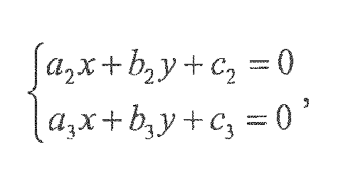
- a lower boundary linear equation of: a 2 x+b 2 y+c 2 = 0,
- a left boundary linear equation of: a 3 x+b 3 y+c 3 = 0, and
- a right boundary linear equation of: a 4 x+b 4 y+c 4 = 0;
- by solving:

- a coordinate of the upper left vertex A in the coordinate system xOy can be obtained, which is indicated by A(xa,ya );
- by solving:

- a coordinate of the lower left vertex B in the coordinate system xOy can be obtained, which is indicated by B(xb ,yb ); and
- by solving:

- coordinates of the points E and F in the coordinate system xOy can be obtained, which are indicated by E(xe ,ye ) and F(xf ,yf ) respectively,
- resulting that:


- A method for determining the position of the faulty line in the coordinate system x'O'y' in the step 5 is as follow:
- the coordinate system x'O'y' is established by taking the upper left vertex A as an origin, taking an extension direction of the upper boundary as the x axis, and taking a direction in which the left boundary extends as the y axis, and the coordinates of the points A, E and F are respectively:


- and a linear equation of the faulty line EF in the coordinate system x'O'y' is:

- According to the invention, the method for cutting the template by taking the position of the faulty line as the boundary is adapted to generate a new sub-template from the standard template, and then a template match identification is performed between the newly generated sub-template and the identification image information of the paper medium to be identified, so that the influence of the faulty line on the template match identification is avoided, and the acceptance rate of the device for identifying the paper medium is improved.
-
-
Figure 1 is a block diagram of a structure of a device for identifying a paper medium according to a preferred embodiment of the invention; -
Figure 2 is a flowchart of a method for identifying a paper medium according to a preferred embodiment of the invention; -
Figure 3 is a schematic diagram of an image obtained by an image sensor when a CIS detects a faulty line; -
Figure 4 is a schematic diagram of match between an image obtained by an image sensor and a standard template when a faulty line is not repaired; -
Figure 5 is a schematic diagram of an image obtained by an image sensor and to be performed a faulty line repair according to a preferred embodiment of the invention, in which the image is set in a coordinate system xOy; -
Figure 6 is a schematic diagram of an image obtaining by an image sensor, in which the image is set in a coordinate system xOy and respective boundary points are set for determining a position of a faulty line; -
Figure 7 is a schematic diagram of an image obtaining by an image sensor, in which the image is set in a coordinate system x'O'y' and a position of a faulty line in the coordinate system x'O'y' is determined; -
Figure 8 is a schematic diagram of a position of a faulty line, in which the faulty line is located at a region to be matched; -
Figure 9 is a schematic diagram of a new template obtained by cutting an existing template along a faulty line as a boundary line; and -
Figure 10 is a schematic diagram of a template match identification between a newly generated template and a template that is not influenced by the faulty line and an image obtained by an image sensor. - Specific embodiments of the invention will be described hereinafter in conjunction with appended drawings, in order to further illustrate the invention.
-
Figure 1 is a block diagram of a structure of a device for identifying apaper medium 100 according to a preferred embodiment of the invention. Thedevice 100 for identifying the paper medium is embedded in a device for processing the paper medium such as ATM (automated teller machine), and transports, through a transfer passage, the paper medium to be identified (such as paper currency) one by one into an image data acquiring part. The device for identifying thepaper medium 100 includes an imagedata acquiring part 10, a faultyline detecting part 20, animage cutting part 30, a standard templatedata storage part 40, acomprehensive analysis part 50, a newtemplate generating part 60 and a determiningpart 70. The image data acquiring part 10 is configured to acquire original image data of the paper medium; the faulty line detecting part 20 is configured to detect whether there is a faulty line in the original image data of the paper medium obtained by the image data acquiring part, and determine a position of the faulty line if there is the faulty line; the image cutting part 30 is configured to cut the original image data to obtain complete image information and identification image information of the effectively identified paper medium; the standard template data storage part 40 is configured to store a standard template which is necessary for identifying the paper medium; the comprehensive analysis part 50 is configured to comprehensively analyzing the complete image information of the paper medium, a result from the faulty line detecting part and data information of the standard template, and determine whether the faulty line at a current position has influence on the template match identification; the new template generating part 60 is configured to, based on an analysis result from the comprehensive analysis part, cutting the original standard template into new sub-templates by taking the faulty line as a boundary in the case that the faulty line has influence on the template match identification, and performing no process on the original standard template when the faulty line has no influence on the template match identification; and the determining part 70 is configured to perform the template match identification on the identification image information of the paper medium by using the newly generated sub-templates and the original standard template that is not influenced by the faulty line, to obtain an identification result. Specifically, theimage cutting part 30 is further configured to cut the identification image information with the faulty line along the faulty line, so as to form identification sub-image information, and the determiningpart 70 is further configured to perform the template match identification respectively between the identification sub-image information formed by the identification image information with the faulty line and the corresponding sub-template formed by the new template generating part, to obtain an identification result. -
Figure 2 is a flowchart of a method for identifying a paper medium by thedevice 100 for identifying the paper medium. The method includes the following steps: step1, loading a paper medium to be identified, the paper medium entering into a transfer passage, and a process beginning; step 2, scanning, by an image sensor, an image of the paper medium when the paper medium passes through the transfer passage, so as to form an original image; step 3, setting, by a faulty line detecting part, the original image obtained by the image sensor in a coordinate system, detecting whether there is a faulty line in the original image, going to step 4 if there is no faulty line in the original image, and further determining a position of the faulty line in the coordinate system if there is the faulty line in the original image; step 4, cutting the original image data to obtain complete image information and identification image information of the paper medium; step 5, setting, by a comprehensive analysis part, the complete image information in a new coordinate system, determining a position of the faulty line in the new coordinate system, detecting whether the faulty line at a current position has influence on a template match identification according to standard template data information in a standard template data storage part, cutting a template that is influenced by the faulty line by taking the current faulty line as a boundary to generate a new sub-template, and performing no process on the template that is not influenced by the faulty line; and step 6, performing the template match identification on the identification image information of the loaded paper medium by using the newly generated sub-template and the template that is not influenced by the faulty line to obtain an identification result, and ending the process. - The image
data acquiring part 10 includes a transmissive sensor for detecting a transmitted image and/or a reflective sensor for detecting a reflected image. When the paper medium is transferred through the transfer passage, the imagedata acquiring part 10 acquires the transmitted image and/or the reflected image of the paper medium, and transfers the obtained transmitted image and/or reflected image to the faultyline detecting part 20. - The faulty
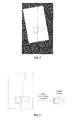
line detecting part 20 detects whether there is a faulty line in the original image obtained by the image sensor at first, and accurately obtains the position of the faulty line in the whole image in the case that there is the faulty line in the original image of the loaded paper medium. Because the image is obtain by CIS in the rectilinear scanning, a black line with the grayscale value approximate to 0 occurs on the original image of the paper medium to be detected if there is any faulty line in the image. Because the position of the CIS faulty line has non-determinacy, the position of the faulty line in the original image of the paper medium to be detected also has non-determinacy. Assuming that when the faulty line (one faulty line) is detected by the CIS, the image obtained by the image sensor is shown asFigure 3 . - If the image cutting and template match identification are performed directly without processing the faulty line region, the match can not be successful when the faulty line is exactly in a certain region on which the template match identification is to be performed, as shown in
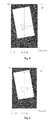
Figure 4 . The identification of the paper medium to be detected will fail, and thus a normal paper medium will be refuse by the financial self-service device (such as ATM) finally. - In this embodiment, the faulty line is detected by using the reflected image of the loaded paper medium that is obtained by the reflective sensor. The reflected image of the loaded paper medium is set in the coordinate system xOy, as shown in
Figure 5 . - Assuming that:
- (1) a grayscale value matrix of a reflected image has x 0 columns and y 0 rows;
- (2) a grayscale value on a position of the yth row and the xth column in the reflected image is indicated by g(x,y); and
- (3) an average grayscale value of the xth column in the reflected image is indicated by g(x);
- If there is no column x that meets the constraint condition (formula 1.1) by traversing the grayscale value matrix of the reflected image, it is determined that there is no faulty line in the reflected image obtained by the image sensor, and thus it can be deduced that there is no CIS faulty line in the device for identifying the paper medium. The process directly performs the step of cutting the complete image of the paper medium to be identified, and the template match identification is performed on the complete image of the paper medium obtained by cutting finally, to obtain a final identification result.
- The image grayscale value matrix of the reflected image has a column of

- In the coordinate system xOy, it is assumed that in the complete image of the paper medium, an upper left vertex is set as A, a lower left vertex is set as B, an upper right vertex is set as D and a lower right vertex is set as C, and the faulty line intersects with an upper boundary and a lower boundary of the complete image of the paper medium at points E and F respectively, as shown in
Figure 6 . The upper, lower, left and right boundary points of the complete image of the paper medium are detected, and the obtained boundary points are linearly fitted respectively to obtain: - an upper boundary linear equation of: a 1 x+b 1 y+c 1 = 0,
- a lower boundary linear equation of: a 2 x+b 2 y+c 2 = 0,
- a left boundary linear equation of: a 3 x+b 3 y+c 3 = 0, and
- a right boundary linear equation of: a 4 x+b 4 y+c 4 = 0.
- By solving:

- By solving:
- By solving:

- Based on the above, the result can be calculated:


- The coordinate system x'O'y' is established by taking the upper left vertex A as an origin, taking an extension direction of the upper boundary as the x axis, and taking an extension direction of the left boundary as the y axis, as shown in
Figure 7 , and the coordinates of the points A, E and F are respectively:


- Thus, the linear equation of the faulty line EF in the coordinate system x'O'y' is:

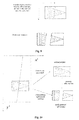
- Based on the position of the faulty line in the coordinate system x'O'y' (formula 1.2) and the standard template information stored in the standard template data storage part, the comprehensive analysis part detects whether there is a region to be matched that is influenced by the faulty line. If the faulty line has no influence on any of the regions to be matched (that is, the faulty line does not pass through any of the regions to be matched), the match identification is performed directly without any other process. If the faulty line is exactly located in a certain region to be matched, as shown in
Figure 8 , the template corresponding to this region is divided into two sub-templates by taking the faulty line as the boundary. - The method for generating the sub-template is shown in
Figure 9 . The standard template data is read from the left to the right, and the reading process turns to the next row of data when the faulty line EF is read. In this way, the new template is obtained by cutting the existing template along the faulty line as the boundary. - Finally, the match identification is obtained by using the newly generated template and the template that is not influenced by the faulty line, to achieve the identification of the loaded paper medium, as shown in
Figure 10 . - According to the invention, with the method for cutting the template by taking the position of the faulty line as the boundary, a new sub-template is generated based on the standard template, and the template match identification is performed between the newly generated sub-template and the image of the paper medium to be identified, so that the influence of the faulty line on the template match identification is avoided, and the acceptance rate of the device for identifying the paper medium is improved.
- The above are only preferred embodiments of the invention, and it is to be noted that the above preferred embodiments should not be interpreted as to limit the invention, and the scope of protection of the invention should be subject to the scope defined in the appended claims. Several modifications and variations can be made by those skilled in the art without deviating from the spirit and scope of the invention, which also fall within the scope of protection of the invention.

for example, assuming that ε1 = 20, ε2 = 20, ε3 = 80 and ε4 = 80, automatic search and detection is performed on the grayscale value matrix of the reflected image obtained by the image sensor.
Claims (7)
- A device for identifying a paper medium, comprising:an image data acquiring part for acquiring original image data of the paper medium;a faulty line detecting part for detecting whether there is a faulty line in the original image data of the paper medium obtained by the image data acquiring part, and obtaining a position of the faulty line if there is the faulty line in the original image data of the paper medium;an image cutting part for cutting the original image data to obtain complete image information and identification image information of an effectively identified paper medium;a standard template data storage part for storing a standard template for identifying the paper medium;a comprehensive analysis part for comprehensively analyzing the complete image information of the paper medium, a result from the faulty line detecting part and data information of the standard template to determine whether the faulty line at a current position influences template match identification;a new template generating part for cutting the standard template into new sub-templates by taking the faulty line as a boundary based on an analysis result from the comprehensive analysis part in the case that the faulty line influences the template match identification, and performing no process on the standard template in the case that the faulty line does not influence the template match identification; anda determining part for performing the template match identification on the identification image information of the paper medium by using the newly generated sub-templates and the standard template that is not influenced by the faulty line, to obtain an identification result.
- The device for identifying the paper medium according to claim 1, wherein the image cutting part is further configured to cut the identification image information with the faulty line based on the faulty line, so as to form identification sub-image information.
- The device for identifying the paper medium according to claim 2, wherein the determining part is further configured to perform the template match identification respectively between the identification sub-image information formed by the identification image information with the faulty line and the sub-template formed by the new template generating part to obtain an identification result.
- A method for identifying a paper medium, comprising:step1, loading a paper medium to be identified, the paper medium entering into a transfer passage, and a process beginning;step 2, scanning, by an image sensor, an image of the paper medium when the paper medium passes through a transfer passage, so as to form an original image;step 3, setting, by a faulty line detecting part, the original image obtained by the image sensor in a coordinate system, and detecting whether there is a faulty line in the original image; the process going to step 4 if there is no faulty line in the original image, and further determining a position of the faulty line in the coordinate system if there is the faulty line in the original image;step 4, cutting original image data to obtain complete image information and identification image information of the paper medium;step 5, setting, by a comprehensive analysis part, the complete image information in a new coordinate system, determining a position of the faulty line in the new coordinate system, detecting whether the faulty line at a current position influences a template match identification according to data information of a standard template in a standard template data storage part, cutting a template that is influenced by the faulty line by taking the current faulty line as a boundary to generate a new sub-template, and performing no process on the standard template that is not influenced by the faulty line; andstep 6, performing the template match identification on the identification image information of the loaded paper medium by using the newly generated sub-template and the standard template that is not influenced by the faulty line to obtain an identification result, and ending the process.
- The method for identifying the paper medium according to claim 4, wherein the step of detecting whether there is a faulty line in the original image in the step 3 comprises:assuming that:(1) a grayscale value matrix of a reflected image has x 0 columns and y 0 rows;(2) a grayscale value at a position of the yth row and the xth column in the reflected image is indicated by g(x,y) ; and(3) an average grayscale value of the xth column in the reflected image is indicated by g(x) ;in accordance with a constraint condition of:
 an automatic search and detection is performed on an image grayscale value matrix obtained by the image sensor; if the above constraint condition is met at a column of x = n 0, that is, the n 0 th column in the image grayscale value matrix, it is determined that there is a faulty line in the image; else, it is determined that there is no faulty line in the image.
 - The method for identifying the paper medium according to claim 4, wherein the step of determining the position of the faulty line in the coordinate system xOy in the step 3 comprises:assuming that in a complete image of the paper medium, an upper left vertex is set as A, a lower left vertex is set as B, an upper right vertex is set as D and a lower right vertex is set as C, and the faulty line intersects with an upper boundary and a lower boundary of the complete image of the paper medium at points E and F respectively, upper, lower, left and right boundary points of the complete image of the paper medium are detected, and a linear fit is performed for each of the obtained boundary points to obtain:an upper boundary linear equation of: a 1 x+b 1 y+c 1 = 0,a lower boundary linear equation of: a 2 x+b 2 y+c 2 = 0a lift boundary linear equation of: a 3 x+b 3 y+c 3 = 0, anda right boundary linear equation of: a 4 x+b 4 y+c 4 = 0;by solving:
 a coordinate of the upper left vertex A in the coordinate system xOy is obtained, which is indicated by A(xa ,ya );by solving:
 a coordinate of the lower left vertex B in the coordinate system xOy is obtained, which is indicated by B(xb ,yb ); andby solving:
 coordinates of the points E and F in the coordinate system xOy is obtained, which are indicated by E(xe ,ye ) and F(xf ,yf ) respectively,resulting that:


- The method for identifying the paper medium according to claim 6, wherein the step of determining the position of the faculty line in the coordinate system x'O'y' in the step 5 comprises:the coordinate system x'O'y' is established by taking the upper left vertex A as an origin, taking an extension direction of the upper boundary as the x axis, and taking an extension direction of the left boundary as the y axis, and the coordinates of the points A, E and F are respectively:

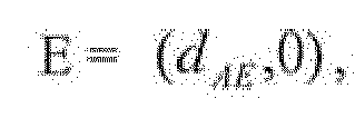
 and the linear equation of the faulty line EF in the coordinate system x'O'y' is:
Applications Claiming Priority (2)
| Application Number | Priority Date | Filing Date | Title |
|---|---|---|---|
| CN201210049059.0A CN102592352B (en) | 2012-02-28 | 2012-02-28 | Recognition device and recognition method of papery medium |
| PCT/CN2012/083594 WO2013127186A1 (en) | 2012-02-28 | 2012-10-26 | Paper medium identifying device and identifying method |
Publications (3)
| Publication Number | Publication Date |
|---|---|
| EP2821974A1 true EP2821974A1 (en) | 2015-01-07 |
| EP2821974A4 EP2821974A4 (en) | 2015-10-28 |
| EP2821974B1 EP2821974B1 (en) | 2018-12-26 |
Family
ID=46480934
Family Applications (1)
| Application Number | Title | Priority Date | Filing Date |
|---|---|---|---|
| EP12870167.9A Active EP2821974B1 (en) | 2012-02-28 | 2012-10-26 | Paper medium identifying device and identifying method |
Country Status (8)
| Country | Link |
|---|---|
| US (1) | US9122944B2 (en) |
| EP (1) | EP2821974B1 (en) |
| CN (1) | CN102592352B (en) |
| AU (1) | AU2012371368B2 (en) |
| CL (1) | CL2014000188A1 (en) |
| TR (1) | TR201820633T4 (en) |
| WO (1) | WO2013127186A1 (en) |
| ZA (1) | ZA201401298B (en) |
Families Citing this family (2)
| Publication number | Priority date | Publication date | Assignee | Title |
|---|---|---|---|---|
| CN102890841B (en) * | 2012-10-08 | 2013-11-27 | 广州广电运通金融电子股份有限公司 | Method and device for identifying valuable documents |
| CN106803307B (en) * | 2016-12-16 | 2023-05-02 | 恒银金融科技股份有限公司 | Banknote face value orientation identification method based on template matching |
Family Cites Families (16)
| Publication number | Priority date | Publication date | Assignee | Title |
|---|---|---|---|---|
| US4776031A (en) * | 1985-03-29 | 1988-10-04 | Canon Kabushiki Kaisha | Image reading apparatus |
| JPH0273573A (en) * | 1988-09-09 | 1990-03-13 | Nec Corp | Read clock signal regenerating circuit |
| JP2896526B2 (en) * | 1990-05-28 | 1999-05-31 | チッソ株式会社 | Modifier composition for polyolefin resin and method for producing polyolefin resin composition |
| JPH06133162A (en) * | 1992-10-20 | 1994-05-13 | Fujitsu General Ltd | Image input device |
| JPH0973573A (en) * | 1995-09-04 | 1997-03-18 | Oki Electric Ind Co Ltd | Medium counterfeit discriminating system |
| JP3423140B2 (en) * | 1996-02-28 | 2003-07-07 | 三洋電機株式会社 | Banknote identification method |
| US6573983B1 (en) * | 1996-11-15 | 2003-06-03 | Diebold, Incorporated | Apparatus and method for processing bank notes and other documents in an automated banking machine |
| CN1185864C (en) | 1997-04-14 | 2005-01-19 | 鸿友科技股份有限公司 | Image restoration device and method |
| JP3369088B2 (en) * | 1997-11-21 | 2003-01-20 | 富士通株式会社 | Paper discrimination device |
| JP3999476B2 (en) | 2001-06-21 | 2007-10-31 | 日立オムロンターミナルソリューションズ株式会社 | Banknote handling equipment |
| JP2004326548A (en) * | 2003-04-25 | 2004-11-18 | Nippon Conlux Co Ltd | Method and apparatus for identifying sheet of paper |
| JP2004326547A (en) * | 2003-04-25 | 2004-11-18 | Nippon Conlux Co Ltd | Method and apparatus for identifying sheet of paper |
| GB2416061A (en) * | 2004-07-07 | 2006-01-11 | Money Controls Ltd | Coin accepting and dispensing apparatus |
| US20070140551A1 (en) * | 2005-12-16 | 2007-06-21 | Chao He | Banknote validation |
| WO2009037791A1 (en) * | 2007-09-21 | 2009-03-26 | Glory Ltd. | Paper money identification device and paper money identification system |
| JP5301239B2 (en) * | 2008-08-09 | 2013-09-25 | 株式会社キーエンス | Pattern model positioning method, image processing apparatus, image processing program, and computer-readable recording medium in image processing |
-
2012
- 2012-02-28 CN CN201210049059.0A patent/CN102592352B/en active Active
- 2012-10-26 AU AU2012371368A patent/AU2012371368B2/en not_active Ceased
- 2012-10-26 TR TR2018/20633T patent/TR201820633T4/en unknown
- 2012-10-26 US US14/233,657 patent/US9122944B2/en active Active
- 2012-10-26 EP EP12870167.9A patent/EP2821974B1/en active Active
- 2012-10-26 WO PCT/CN2012/083594 patent/WO2013127186A1/en not_active Ceased
-
2014
- 2014-01-24 CL CL2014000188A patent/CL2014000188A1/en unknown
- 2014-02-20 ZA ZA2014/01298A patent/ZA201401298B/en unknown
Also Published As
| Publication number | Publication date |
|---|---|
| AU2012371368B2 (en) | 2014-12-11 |
| CN102592352B (en) | 2014-02-12 |
| TR201820633T4 (en) | 2019-01-21 |
| US9122944B2 (en) | 2015-09-01 |
| CL2014000188A1 (en) | 2014-06-13 |
| ZA201401298B (en) | 2014-12-23 |
| US20140126803A1 (en) | 2014-05-08 |
| AU2012371368A1 (en) | 2014-01-16 |
| EP2821974B1 (en) | 2018-12-26 |
| CN102592352A (en) | 2012-07-18 |
| EP2821974A4 (en) | 2015-10-28 |
| WO2013127186A1 (en) | 2013-09-06 |
Similar Documents
| Publication | Publication Date | Title |
|---|---|---|
| EP2889846B1 (en) | Paper money identification method and device | |
| EP2187359B1 (en) | Paper sheet identification device and paper sheet identification method | |
| CN104751559B (en) | Banknote tester and banknote detection method | |
| EP2631881A1 (en) | Banknote double-note detection method and device and automated terminal | |
| EP2660787B1 (en) | Defect Categorisation in a digital image | |
| CN103279735B (en) | Dust stratification detection method and system in a kind of financial document identification module | |
| EP3252710B1 (en) | Banknote crack detection method and apparatus | |
| CN106127930B (en) | A kind of method and system detecting banknote security line integrality | |
| AU2013330103B2 (en) | Valuable document authentication method and device | |
| US20090289121A1 (en) | Bar code processing apparatus | |
| CN104346858A (en) | Paper currency face value identification method and device based on magnetic image | |
| KR102419540B1 (en) | Determining the module size of an optical code | |
| US10049523B2 (en) | Method and device for detecting overlapped bank notes | |
| EP2620920B1 (en) | Valuable document identification method and system | |
| CN103604814A (en) | Detection method for chip defect | |
| CN104298947A (en) | Method and device for accurately positioning two-dimensional bar code | |
| CN103021069A (en) | High-speed note image acquisition processing system and acquisition processing method thereof | |
| CN104915652A (en) | Fingerprint image restoration method and device | |
| JP2017521011A (en) | Symbol optical detection method | |
| EP2821974B1 (en) | Paper medium identifying device and identifying method | |
| EP3916673B1 (en) | Method for determining striation properties of fatigue striations and for determining the presence of fatigue damage | |
| CN201628690U (en) | Print detecting system | |
| US11710331B2 (en) | Systems and methods for separating ligature characters in digitized document images | |
| CN102592351B (en) | Authentication method of papery medium | |
| CN113256870B (en) | Method and device for detecting thickness abnormality of sheet medium, storage medium and equipment |
Legal Events
| Date | Code | Title | Description |
|---|---|---|---|
| PUAI | Public reference made under article 153(3) epc to a published international application that has entered the european phase |
Free format text: ORIGINAL CODE: 0009012 |
|
| 17P | Request for examination filed |
Effective date: 20131230 |
|
| AK | Designated contracting states |
Kind code of ref document: A1 Designated state(s): AL AT BE BG CH CY CZ DE DK EE ES FI FR GB GR HR HU IE IS IT LI LT LU LV MC MK MT NL NO PL PT RO RS SE SI SK SM TR |
|
| AX | Request for extension of the european patent |
Extension state: BA ME |
|
| DAX | Request for extension of the european patent (deleted) | ||
| RA4 | Supplementary search report drawn up and despatched (corrected) |
Effective date: 20150928 |
|
| RIC1 | Information provided on ipc code assigned before grant |
Ipc: G07D 7/20 20060101AFI20150922BHEP Ipc: H04N 1/387 20060101ALI20150922BHEP |
|
| STAA | Information on the status of an ep patent application or granted ep patent |
Free format text: STATUS: EXAMINATION IS IN PROGRESS |
|
| 17Q | First examination report despatched |
Effective date: 20180322 |
|
| GRAP | Despatch of communication of intention to grant a patent |
Free format text: ORIGINAL CODE: EPIDOSNIGR1 |
|
| STAA | Information on the status of an ep patent application or granted ep patent |
Free format text: STATUS: GRANT OF PATENT IS INTENDED |
|
| INTG | Intention to grant announced |
Effective date: 20180711 |
|
| GRAS | Grant fee paid |
Free format text: ORIGINAL CODE: EPIDOSNIGR3 |
|
| GRAA | (expected) grant |
Free format text: ORIGINAL CODE: 0009210 |
|
| STAA | Information on the status of an ep patent application or granted ep patent |
Free format text: STATUS: THE PATENT HAS BEEN GRANTED |
|
| AK | Designated contracting states |
Kind code of ref document: B1 Designated state(s): AL AT BE BG CH CY CZ DE DK EE ES FI FR GB GR HR HU IE IS IT LI LT LU LV MC MK MT NL NO PL PT RO RS SE SI SK SM TR |
|
| REG | Reference to a national code |
Ref country code: GB Ref legal event code: FG4D |
|
| REG | Reference to a national code |
Ref country code: CH Ref legal event code: EP |
|
| REG | Reference to a national code |
Ref country code: AT Ref legal event code: REF Ref document number: 1082485 Country of ref document: AT Kind code of ref document: T Effective date: 20190115 |
|
| REG | Reference to a national code |
Ref country code: DE Ref legal event code: R096 Ref document number: 602012055294 Country of ref document: DE |
|
| REG | Reference to a national code |
Ref country code: IE Ref legal event code: FG4D |
|
| PG25 | Lapsed in a contracting state [announced via postgrant information from national office to epo] |
Ref country code: LT Free format text: LAPSE BECAUSE OF FAILURE TO SUBMIT A TRANSLATION OF THE DESCRIPTION OR TO PAY THE FEE WITHIN THE PRESCRIBED TIME-LIMIT Effective date: 20181226 Ref country code: NO Free format text: LAPSE BECAUSE OF FAILURE TO SUBMIT A TRANSLATION OF THE DESCRIPTION OR TO PAY THE FEE WITHIN THE PRESCRIBED TIME-LIMIT Effective date: 20190326 Ref country code: FI Free format text: LAPSE BECAUSE OF FAILURE TO SUBMIT A TRANSLATION OF THE DESCRIPTION OR TO PAY THE FEE WITHIN THE PRESCRIBED TIME-LIMIT Effective date: 20181226 Ref country code: LV Free format text: LAPSE BECAUSE OF FAILURE TO SUBMIT A TRANSLATION OF THE DESCRIPTION OR TO PAY THE FEE WITHIN THE PRESCRIBED TIME-LIMIT Effective date: 20181226 Ref country code: BG Free format text: LAPSE BECAUSE OF FAILURE TO SUBMIT A TRANSLATION OF THE DESCRIPTION OR TO PAY THE FEE WITHIN THE PRESCRIBED TIME-LIMIT Effective date: 20190326 Ref country code: HR Free format text: LAPSE BECAUSE OF FAILURE TO SUBMIT A TRANSLATION OF THE DESCRIPTION OR TO PAY THE FEE WITHIN THE PRESCRIBED TIME-LIMIT Effective date: 20181226 |
|
| REG | Reference to a national code |
Ref country code: NL Ref legal event code: MP Effective date: 20181226 |
|
| REG | Reference to a national code |
Ref country code: LT Ref legal event code: MG4D |
|
| PG25 | Lapsed in a contracting state [announced via postgrant information from national office to epo] |
Ref country code: SE Free format text: LAPSE BECAUSE OF FAILURE TO SUBMIT A TRANSLATION OF THE DESCRIPTION OR TO PAY THE FEE WITHIN THE PRESCRIBED TIME-LIMIT Effective date: 20181226 Ref country code: AL Free format text: LAPSE BECAUSE OF FAILURE TO SUBMIT A TRANSLATION OF THE DESCRIPTION OR TO PAY THE FEE WITHIN THE PRESCRIBED TIME-LIMIT Effective date: 20181226 Ref country code: RS Free format text: LAPSE BECAUSE OF FAILURE TO SUBMIT A TRANSLATION OF THE DESCRIPTION OR TO PAY THE FEE WITHIN THE PRESCRIBED TIME-LIMIT Effective date: 20181226 Ref country code: GR Free format text: LAPSE BECAUSE OF FAILURE TO SUBMIT A TRANSLATION OF THE DESCRIPTION OR TO PAY THE FEE WITHIN THE PRESCRIBED TIME-LIMIT Effective date: 20190327 |
|
| PG25 | Lapsed in a contracting state [announced via postgrant information from national office to epo] |
Ref country code: NL Free format text: LAPSE BECAUSE OF FAILURE TO SUBMIT A TRANSLATION OF THE DESCRIPTION OR TO PAY THE FEE WITHIN THE PRESCRIBED TIME-LIMIT Effective date: 20181226 |
|
| PG25 | Lapsed in a contracting state [announced via postgrant information from national office to epo] |
Ref country code: PL Free format text: LAPSE BECAUSE OF FAILURE TO SUBMIT A TRANSLATION OF THE DESCRIPTION OR TO PAY THE FEE WITHIN THE PRESCRIBED TIME-LIMIT Effective date: 20181226 Ref country code: PT Free format text: LAPSE BECAUSE OF FAILURE TO SUBMIT A TRANSLATION OF THE DESCRIPTION OR TO PAY THE FEE WITHIN THE PRESCRIBED TIME-LIMIT Effective date: 20190426 Ref country code: CZ Free format text: LAPSE BECAUSE OF FAILURE TO SUBMIT A TRANSLATION OF THE DESCRIPTION OR TO PAY THE FEE WITHIN THE PRESCRIBED TIME-LIMIT Effective date: 20181226 Ref country code: ES Free format text: LAPSE BECAUSE OF FAILURE TO SUBMIT A TRANSLATION OF THE DESCRIPTION OR TO PAY THE FEE WITHIN THE PRESCRIBED TIME-LIMIT Effective date: 20181226 |
|
| PG25 | Lapsed in a contracting state [announced via postgrant information from national office to epo] |
Ref country code: RO Free format text: LAPSE BECAUSE OF FAILURE TO SUBMIT A TRANSLATION OF THE DESCRIPTION OR TO PAY THE FEE WITHIN THE PRESCRIBED TIME-LIMIT Effective date: 20181226 Ref country code: EE Free format text: LAPSE BECAUSE OF FAILURE TO SUBMIT A TRANSLATION OF THE DESCRIPTION OR TO PAY THE FEE WITHIN THE PRESCRIBED TIME-LIMIT Effective date: 20181226 Ref country code: SM Free format text: LAPSE BECAUSE OF FAILURE TO SUBMIT A TRANSLATION OF THE DESCRIPTION OR TO PAY THE FEE WITHIN THE PRESCRIBED TIME-LIMIT Effective date: 20181226 Ref country code: IS Free format text: LAPSE BECAUSE OF FAILURE TO SUBMIT A TRANSLATION OF THE DESCRIPTION OR TO PAY THE FEE WITHIN THE PRESCRIBED TIME-LIMIT Effective date: 20190426 Ref country code: SK Free format text: LAPSE BECAUSE OF FAILURE TO SUBMIT A TRANSLATION OF THE DESCRIPTION OR TO PAY THE FEE WITHIN THE PRESCRIBED TIME-LIMIT Effective date: 20181226 |
|
| REG | Reference to a national code |
Ref country code: DE Ref legal event code: R097 Ref document number: 602012055294 Country of ref document: DE |
|
| PG25 | Lapsed in a contracting state [announced via postgrant information from national office to epo] |
Ref country code: DK Free format text: LAPSE BECAUSE OF FAILURE TO SUBMIT A TRANSLATION OF THE DESCRIPTION OR TO PAY THE FEE WITHIN THE PRESCRIBED TIME-LIMIT Effective date: 20181226 |
|
| PLBE | No opposition filed within time limit |
Free format text: ORIGINAL CODE: 0009261 |
|
| STAA | Information on the status of an ep patent application or granted ep patent |
Free format text: STATUS: NO OPPOSITION FILED WITHIN TIME LIMIT |
|
| 26N | No opposition filed |
Effective date: 20190927 |
|
| PG25 | Lapsed in a contracting state [announced via postgrant information from national office to epo] |
Ref country code: SI Free format text: LAPSE BECAUSE OF FAILURE TO SUBMIT A TRANSLATION OF THE DESCRIPTION OR TO PAY THE FEE WITHIN THE PRESCRIBED TIME-LIMIT Effective date: 20181226 |
|
| PG25 | Lapsed in a contracting state [announced via postgrant information from national office to epo] |
Ref country code: MC Free format text: LAPSE BECAUSE OF FAILURE TO SUBMIT A TRANSLATION OF THE DESCRIPTION OR TO PAY THE FEE WITHIN THE PRESCRIBED TIME-LIMIT Effective date: 20181226 |
|
| REG | Reference to a national code |
Ref country code: CH Ref legal event code: PL |
|
| PG25 | Lapsed in a contracting state [announced via postgrant information from national office to epo] |
Ref country code: LU Free format text: LAPSE BECAUSE OF NON-PAYMENT OF DUE FEES Effective date: 20191026 Ref country code: LI Free format text: LAPSE BECAUSE OF NON-PAYMENT OF DUE FEES Effective date: 20191031 Ref country code: CH Free format text: LAPSE BECAUSE OF NON-PAYMENT OF DUE FEES Effective date: 20191031 |
|
| REG | Reference to a national code |
Ref country code: BE Ref legal event code: MM Effective date: 20191031 |
|
| PG25 | Lapsed in a contracting state [announced via postgrant information from national office to epo] |
Ref country code: BE Free format text: LAPSE BECAUSE OF NON-PAYMENT OF DUE FEES Effective date: 20191031 |
|
| PG25 | Lapsed in a contracting state [announced via postgrant information from national office to epo] |
Ref country code: IE Free format text: LAPSE BECAUSE OF NON-PAYMENT OF DUE FEES Effective date: 20191026 |
|
| REG | Reference to a national code |
Ref country code: AT Ref legal event code: UEP Ref document number: 1082485 Country of ref document: AT Kind code of ref document: T Effective date: 20181226 |
|
| PGFP | Annual fee paid to national office [announced via postgrant information from national office to epo] |
Ref country code: FR Payment date: 20210129 Year of fee payment: 9 Ref country code: IT Payment date: 20210211 Year of fee payment: 9 |
|
| PG25 | Lapsed in a contracting state [announced via postgrant information from national office to epo] |
Ref country code: CY Free format text: LAPSE BECAUSE OF FAILURE TO SUBMIT A TRANSLATION OF THE DESCRIPTION OR TO PAY THE FEE WITHIN THE PRESCRIBED TIME-LIMIT Effective date: 20181226 |
|
| PGFP | Annual fee paid to national office [announced via postgrant information from national office to epo] |
Ref country code: GB Payment date: 20210115 Year of fee payment: 9 Ref country code: DE Payment date: 20210209 Year of fee payment: 9 Ref country code: TR Payment date: 20210115 Year of fee payment: 9 Ref country code: AT Payment date: 20210126 Year of fee payment: 9 |
|
| PG25 | Lapsed in a contracting state [announced via postgrant information from national office to epo] |
Ref country code: HU Free format text: LAPSE BECAUSE OF FAILURE TO SUBMIT A TRANSLATION OF THE DESCRIPTION OR TO PAY THE FEE WITHIN THE PRESCRIBED TIME-LIMIT; INVALID AB INITIO Effective date: 20121026 Ref country code: MT Free format text: LAPSE BECAUSE OF FAILURE TO SUBMIT A TRANSLATION OF THE DESCRIPTION OR TO PAY THE FEE WITHIN THE PRESCRIBED TIME-LIMIT Effective date: 20181226 |
|
| REG | Reference to a national code |
Ref country code: DE Ref legal event code: R119 Ref document number: 602012055294 Country of ref document: DE |
|
| REG | Reference to a national code |
Ref country code: AT Ref legal event code: MM01 Ref document number: 1082485 Country of ref document: AT Kind code of ref document: T Effective date: 20211026 |
|
| GBPC | Gb: european patent ceased through non-payment of renewal fee |
Effective date: 20211026 |
|
| PG25 | Lapsed in a contracting state [announced via postgrant information from national office to epo] |
Ref country code: MK Free format text: LAPSE BECAUSE OF FAILURE TO SUBMIT A TRANSLATION OF THE DESCRIPTION OR TO PAY THE FEE WITHIN THE PRESCRIBED TIME-LIMIT Effective date: 20181226 |
|
| PG25 | Lapsed in a contracting state [announced via postgrant information from national office to epo] |
Ref country code: GB Free format text: LAPSE BECAUSE OF NON-PAYMENT OF DUE FEES Effective date: 20211026 Ref country code: DE Free format text: LAPSE BECAUSE OF NON-PAYMENT OF DUE FEES Effective date: 20220503 |
|
| PG25 | Lapsed in a contracting state [announced via postgrant information from national office to epo] |
Ref country code: AT Free format text: LAPSE BECAUSE OF NON-PAYMENT OF DUE FEES Effective date: 20211026 |
|
| PG25 | Lapsed in a contracting state [announced via postgrant information from national office to epo] |
Ref country code: FR Free format text: LAPSE BECAUSE OF NON-PAYMENT OF DUE FEES Effective date: 20211031 |
|
| PG25 | Lapsed in a contracting state [announced via postgrant information from national office to epo] |
Ref country code: IT Free format text: LAPSE BECAUSE OF NON-PAYMENT OF DUE FEES Effective date: 20211026 |